
DMH-10B - Walking Aid Gabor - Free user manual and instructions
Find the device manual for free DMH-10B Gabor in PDF.

| Product Type | Desktop Monitor Mount |
| Brand | Gabor |
| Model | DMH-10B |
| Compatible Monitor Size | 17 to 57 inches (43.2 to 144.8 cm) |
| Maximum Load (Curved Monitor) | 48.4 lb (22 kg) |
| Maximum Load (Flat Monitor) | 59.4 lb (27 kg) |
| VESA Compatibility | 75x75, 100x100, 200x100, 200x200 mm |
| Monitor Tilt Range | +60° to -20° |
| Monitor Arm Swivel | ±90° |
| Base Arm Pivot | 360° |
| Height Adjustment Range | 12.8 to 25.75 inches (32.5 to 65.4 cm) |
| Maximum Reach | 23 inches (58.5 cm) |
| Installation Options | Clamp or Grommet |
| Maximum Desktop Thickness (Clamp) | 1.8 inches (45 mm) |
| Maximum Desktop Thickness (Grommet) | 1.6 inches (40 mm) |
| Grommet Hole Diameter | 0.4 to 2.4 inches (10 to 60 mm) |
| Weight (Mount Only) | 10.8 lb (4.9 kg) |
| Package Weight | 13.1 lb (5.9 kg) |
| Package Dimensions | 17.2 x 9.8 x 5 inches (43.8 x 25 x 12.7 cm) |
| Cable Management | Yes, with top and bottom cable guides |
| Adjustable Gas Spring Tension | Yes, for arm balance |
| Monitor Orientation Rotation | ±90° with safety screw |
| Warranty | 1 Year Limited |
| Cleaning Instructions | Use only a soft, dry cloth |
Frequently Asked Questions - DMH-10B Gabor
User questions about DMH-10B Gabor
0 question about this device. Answer the ones you know or ask your own.
Ask a new question about this device
Download the instructions for your Walking Aid in PDF format for free! Find your manual DMH-10B - Gabor and take your electronic device back in hand. On this page are published all the documents necessary for the use of your device. DMH-10B by Gabor.
USER MANUAL DMH-10B Gabor
for up to 57 in. Flat and Curved Desktop Computer Monitors
User Manual
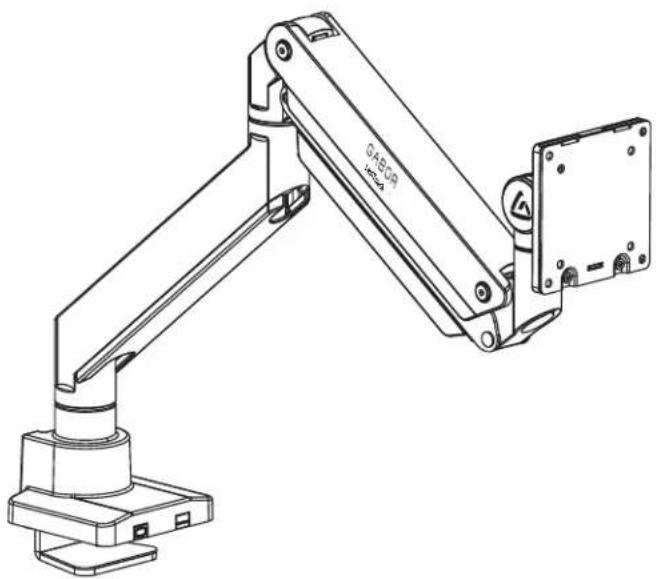
natural_image
Technical line drawing of a mechanical arm with base mount and mounting bracket (no text or symbols)Thank you for choosing Gabor.
The Gabor Levitouch desktop monitor mount is a heavy-duty mount that's designed to hold a 57-inch flat or curved monitor and deliver optimum viewing angles whether you're sitting or standing. It clamps to desks and tablets and will preserve desk space while it securely holds oversize monitors when you're gaming, video editing, or watching a movie. The articulating arm has adjustable gos-spring tension that ensures monitor stability and glides into place when changing the monitor's height, tilt, and orientation.
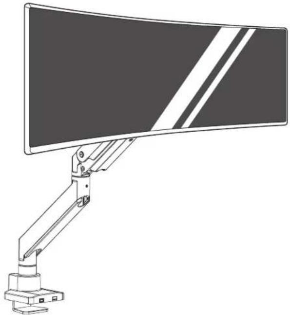
natural_image
Line drawing of a computer monitor with a vertical scroll and adjustable arm (no text or symbols)Safety Warnings
- Please read and follow the instructions, and keep this manual in a safe place.
- When installing this product, be sure to refer to the mounting instructions detailed in this manual; failure to abide by the mounting instructions may void the product's warranty.
- Do not use this product for uses other than those intended; the exact specification, size parameters, and weight limits are found both on the product box and in the instruction manual.
- Gabor takes no responsibility for any product damage or personal injury resulting from mishandling, incorrect mounting, faulty assembly, or improper use of this product.
-
This product may contain small parts which can possibly pose a choking hazard; keep out of reach of children and pets.
-
Make sure this product is intact and there are no missing parts.
- Mounting surfaces should be sturdy and flat. Do not install this product on a weak, uneven surface.
- Do not mount the device on structures that may be affected by vibrations or noticeable impacts; do not install near a heater, fireplace, or any other source of direct heat energy.
- Clean this product with only a soft, dry cloth.
- All images are for illustrative purposes only.
Product Specifications
Monitor Display Size
17 to 57 in. (43.2 to 144.8 cm)
Maximum Load
Curved: 48.4 lb. [22 kg]
Flat: 59.4 lb. (27 kg)
Maximum Desktop Thickness
Clamp: 1.8 in. (45 mm)
Grommet: 1.6 in. (40 mm)
Maximum Reach
23 in. (58.5 cm)
VESA Standards
75×75 mm
100×100mm
200×100mm
200×200mm
Monitor Tilt
+60° to -20°
Monitor Arm Swivel
±90°
Base Arm Pivot
360°
Arm Height Adjustment
12.8 to 25.75 in. (32.5 to 65.4 cm)
Weight (without monitor)
10.8 lb.(4.9 kg)
Package Weight
13.1 lb. [5.9 kg]
Package Dimensions
17.2×9.8×5 in. (43.8×25×12.7 cm)

Overview
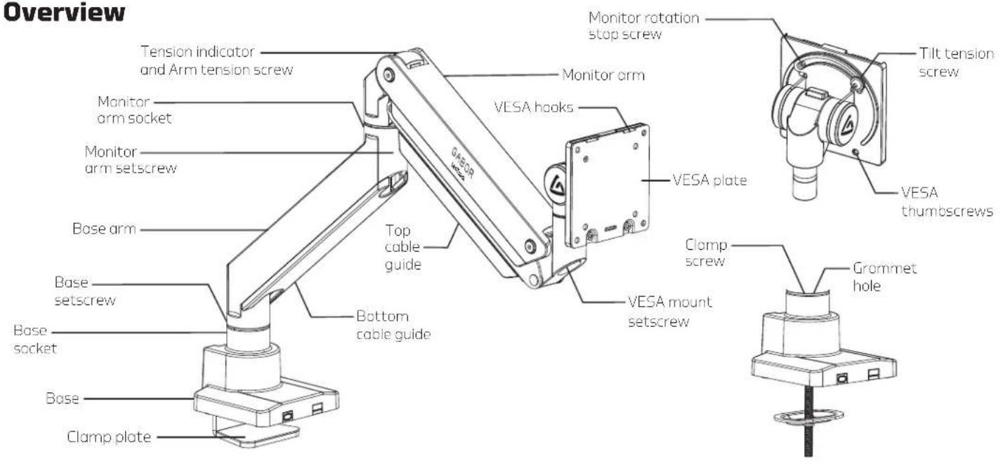
Overview

Clamp Installation
For desks or tabletops 0.4 to 1.8 in. (10 to 45 mm) thick


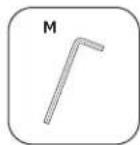
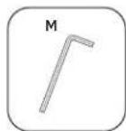
- Use hex key (M) to loosen the clamp screw, and widen the clamp to the thickness of the mounting surface.
- Slide the clamp onto the edge of the surface, and tighten the clamp until it's secure.

natural_image
Technical line drawing of a mechanical device with a lever and base plate (no text or symbols)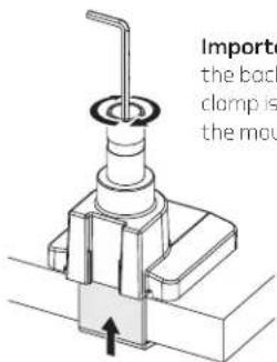
Important! Make sure the back edge of the clamp is flush against the mounting surface.
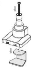
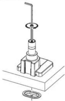
Grommet Installation
For desks or tabletops 0.4 inch to 1.6 in. (10 to 40 mm) thick
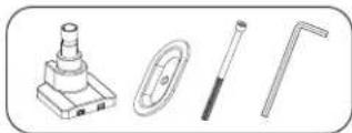
Important! Precrilled holes should be between 0.4 to 2.4 inches (Ø10-60mm) in diameter.
- Use hex key (M) to remove the clamp screw and clamp from the base.
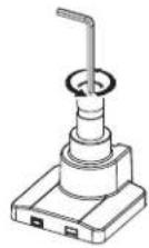
- Insert the carriage bolt (C) through the grammet hole and the predrilled hole in the surface. Screw the flange (E) onto the end of the bolt. Make sure the flat edge of the flange faces up.
- Tighten the flange with hex key (M) until the base is securely attached to the surface.
natural_image
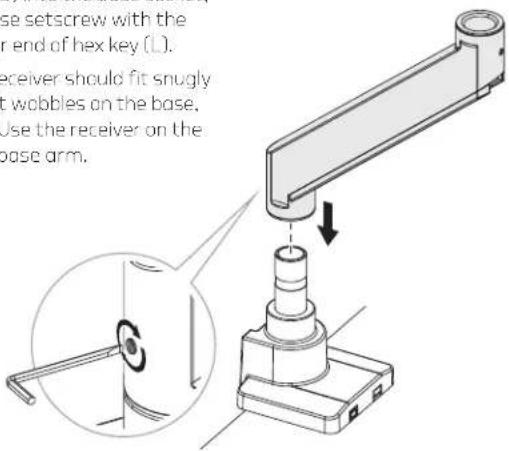
Technical line drawing of a mechanical assembly with a central shaft and base mount (no text or symbols)Attaching the Arms
The base arm has two equally sized sockets and the slip-off cable guide.
The top arm has the screw on cable guide.
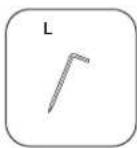
- Place the base arm (B) into the base socket, and tighten the base setscrew with the slotted screwdriver end of hex key (L).
Note: The base arm's receiver should fit snugly onto the base. If it wobbles on the base, it's upside down. Use the receiver on the other end of the base arm.
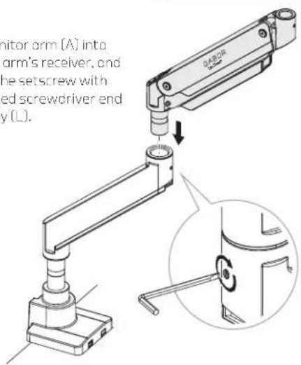
- Fit the monitor arm (A) into the base arm's receiver, and tighten the setscrew with the slotted screwdriver end of hex key (L).

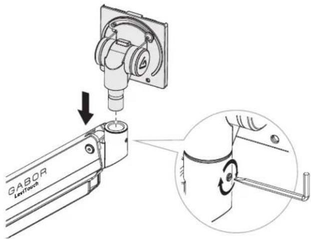
Attaching the Monitor Mount

- Attach the monitor mount to the arm and tighten the setscrew with the slotted screwdriver end of hex key (L).
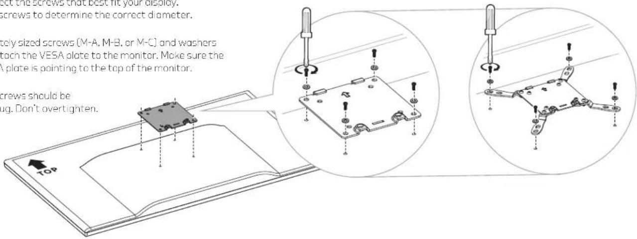
Attaching the VESA Plate to a Monitor
Attaching the VESA Plate to a Monitor (cont.)
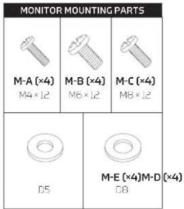
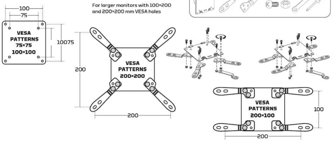
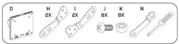
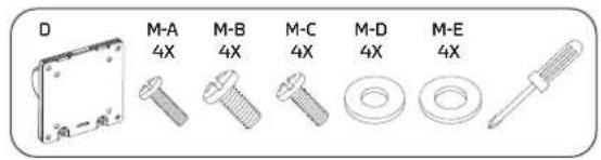
Selecting the Right VESA Mounting Hardware for Your Display
A variety of screws are included to fit VESA standards on the backs of most displays. Select the screws that best fit your display. Hand-thread the screws to determine the correct diameter.
Use the appropriately sized screws (M-A, M-B, or M-C) and washers (M-D or M-E) to attach the VESA plate to the monitor. Make sure the arrow on the VESA plate is pointing to the top of the monitor.
Important! The screws should be tightened until snug. Don't overtighten.
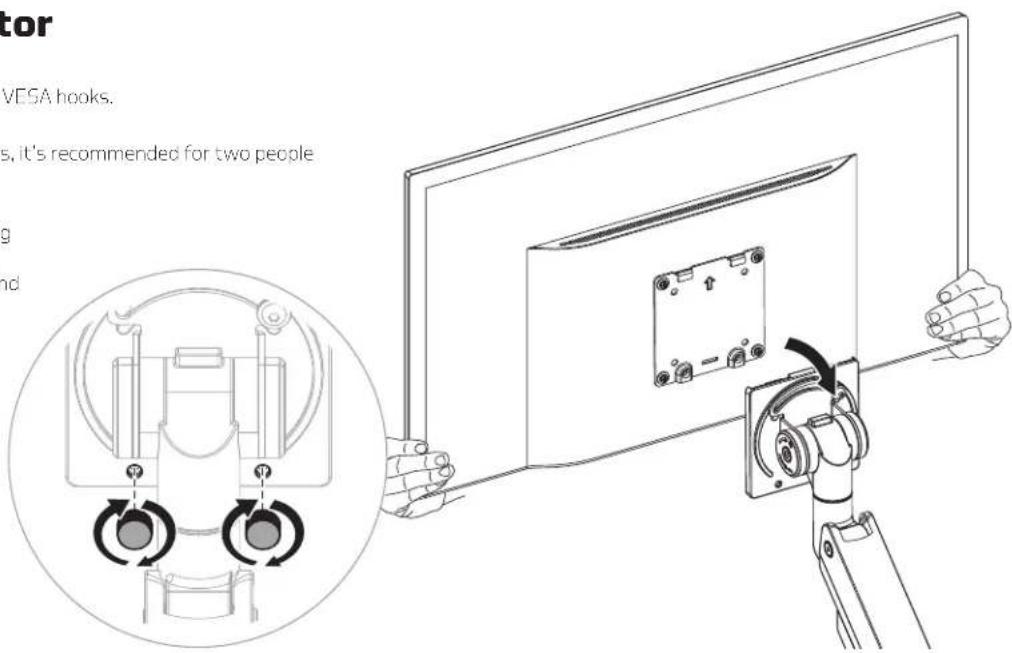
Attaching the Monitor
Hang the VESA plate and monitor on the VESA hooks.
Important! For large and heavy monitors, it's recommended for two people to hang the monitor.
Make sure the monitor is securely hanging on the VESA receiver before releasing it. Then replace the VESA thumbscrews, and tighten until secure.

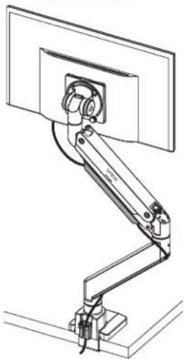
Balancing the Arm
When the arm is adjusted to the ideal tension, it will hold the monitor in position indefinitely.
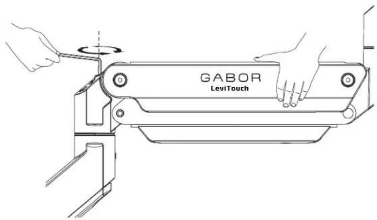
To adjust the arm tension, follow these steps:
Support the monitor with one hand, and position the arm and monitor so the arm is horizontal.
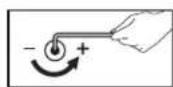
- If the arm drops due to the weight of the monitor, use hex key (M) to turn the arm tension screw counterclockwise toward the + icon.
- It the arm rises, use the hex key to turn the arm tension screw clockwise toward the - icon.

Important! Do not overtighten or overloosen the tension adjustment screw.

Adjusting Arm Swivel

Adjusting the Tilt Angle
The three swivel points on the monitor mount can be adjusted by tightening or loosening the setscrews with the slotted end of hex key (L).
If the tilt angle of the monitor won't move, use hex key (M) to slightly loosen the tilt tension screw by turning it toward the - icon.
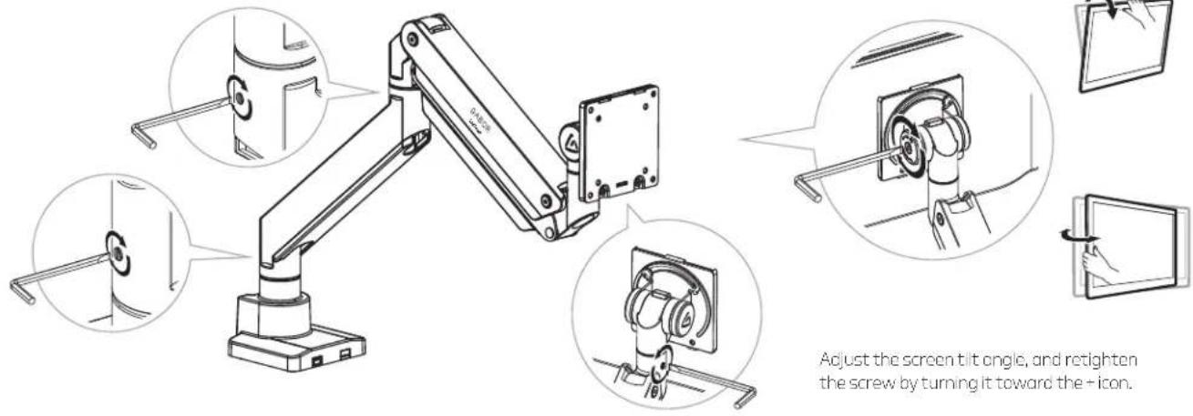
Adjust the screen tilt angle, and retighten the screw by turning it toward the + icon.
Adjusting the Monitor Orientation
The monitor mount lets you rotate the screen by 90° in either direction. A safety screw is included to prevent over rotation.

natural_image
Technical line drawing of a mechanical arm assembly mounted on a platform (no text or symbols visible)Organizing Cables
Power and monitor cables can be neatly run through the top and bottom cable guides on the arms.
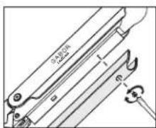
Top Cable Guide
Use a Phillips screwdriver to unscrew the top cable guide screw, and slide it up toward the monitor to remove it.
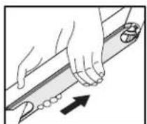
Botton Cable Guide
Remove the bottom cable guide by sliding it up toward the monitor. Place the cables in the guide, align the notches and slide the cable guide back toward the base until it stops into place.
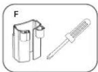

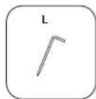
Storing the Hex Keys
Store the hex keys and keep them handy for future adjustments by placing them in the holder (F) and sliding the holder onto the slots on the back of the base.
One-Year Limited Warranty
This Gabor product is warranted to the original purchaser to be free from defects in materials and workmanship under normal consumer use for a period of one (1) year from the original purchase date or thirty (30) days after replacement, whichever occurs later. The warranty provider's responsibility with respect to this limited warranty shall be limited solely to repair or replacement, at the provider's discretion, of any product that fails during normal use of this product in its intended manner and in its intended environment. Inoperability of the product or part(s) shall be determined by the warranty provider. If the product has been discontinued, the warranty provider reserves the right to replace it with a model of equivalent quality and function.
This warranty does not cover damage or defect caused by misuse, neglect, accident, alteration, abuse, improper installation or maintenance. EXCEPT AS PROVIDED HEREIN, THE WARRANTY PROVIDER MAKES NEITHER ANY EXPRESS WARRANTIES NOR ANY IMPLIED WARRANTIES, INCLUDING BUT NOT LIMITED TO ANY IMPLIED WARRANTY OF MERCHANTABILITY OR FITNESS FOR A PARTICULAR PURPOSE. This warranty provides you with specific legal rights, and you may also have additional rights that vary from state to state.
To obtain warranty coverage, contact the Gabor Customer Service Department to obtain a return merchandise authorization ("RMA") number, and return the defective product to Gabor along with the RMA number and proof of purchase. Shipment of the defective product is at the purchaser's own risk and expense.
For more information or to arrange service, visit www.madebygabor.com or call Customer Service at 212-594-2353.
Product warranty provided by the Gradus Group.
www.grodusgroup.com
Gabor is a registered trademark of the Gradus Group. © 2024 Gradus Group LLC. All Rights Reserved.

GABOR®
A Gradus Group Brand


- Thank you for choosing Gabor.
- Safety Warnings
- Product Specifications
- Clamp Installation
- Grommet Installation
- Attaching the Arms
- Attaching the Monitor Mount
- Attaching the VESA Plate to a Monitor (cont.)
- Selecting the Right VESA Mounting Hardware for Your Display
- Attaching the Monitor
- Balancing the Arm
- Adjusting Arm Swivel
- Adjusting the Tilt Angle
- Adjusting the Monitor Orientation
- Organizing Cables
- One-Year Limited Warranty
Brand : Gabor
Model : DMH-10B
Category : Walking Aid