Vi30210 - NAS Vigitron - Free user manual and instructions
Find the device manual for free Vi30210 Vigitron in PDF.

| Product Type | Industrial L2+ Managed PoE+ Switch |
| Model | Vi30210 |
| Ports | 8 x 10/100/1000Base-T PoE+ (ports 1-8), 2 x combo 10/100/1000Base-T/SFP (ports 9-10), 2 x 100/1000Mbps SFP (ports 11-12) |
| PoE Standard | IEEE 802.3af/at, up to 30W per port |
| Total PoE Budget | Up to 480W (depending on power supply) |
| Switching Capacity | 20 Gbps |
| Forwarding Rate | 35.712 Mpps |
| MAC Address Table | 8K |
| Dimensions (W x D x H) | 4.375 x 2.0 x 6.625 inches (111 x 51 x 168 mm) |
| Weight | 1.9 lbs (0.86 kg) |
| Power Input | 48-57 VDC (dual redundant inputs) |
| Power Consumption | 20W (without PoE load) |
| Operating Temperature | -30°C to +70°C (-22°F to 158°F) |
| Humidity | 5% to 90% (non-condensing) |
| Management | Web GUI, Telnet, SSH, SNMP v1/v2c/v3, RMON, Console (RJ-45) |
| VLAN Support | IEEE 802.1Q, up to 4094 VLANs, Voice VLAN, Private VLAN |
| Redundancy | STP, RSTP, MSTP, ERPS, Link Aggregation (LACP), Loop Protection |
| Security | 802.1X, ACL, IP Source Guard, ARP Inspection, SSH/SSL, RADIUS/TACACS+ |
| Mounting | DIN rail, wall, desktop (bracket included) |
| Cooling | Fanless, conformal coating |
| Warranty | Limited lifetime (see manual for details) |
Frequently Asked Questions - Vi30210 Vigitron
User questions about Vi30210 Vigitron
0 question about this device. Answer the ones you know or ask your own.
Ask a new question about this device
Download the instructions for your NAS in PDF format for free! Find your manual Vi30210 - Vigitron and take your electronic device back in hand. On this page are published all the documents necessary for the use of your device. Vi30210 by Vigitron.
USER MANUAL Vi30210 Vigitron
MaxiiNet™ Vi30210 Operation and Installation Manual
8 +2 Port Series PoE+ L2 Plus Industrial Managed Switch
Copyright © 2021 Vigitron, Inc. All rights reserved. The products and programs described in this user's manual are licensed products of Vigitron, Inc. This user's manual contains proprietary information protected by copyright, and this user's manual and all accompanying hardware, software and documentation are copyrighted. No parts of this user's manual may be copied, photocopied, reproduced, translated or reduced to any electronic medium or machine-readable from by any means electronic or mechanical. This also Includes photocopying, recording, or information storage and retrieval systems, for any purpose other than the purchaser's personal use, and without the prior express written permission of Vigitron, Inc.
Purpose
This guide gives specific information on how to operate and use the management functions of the switch.
Audience
The guide is intended for use by network administrators who are responsible for operating and maintaining network equipment. Consequently, it assumes a basic working knowledge of general switch functions, the Internet Protocol (IP), and Simple Network Management Protocol (SNMP).
The following conventions are used throughout this guide to show information:
Conventions

NOTE: Emphasizes important information or calls your attention to related features or instructions.

WARNING: Alerts you to a potential hazard that could cause personal injury.

CAUTION: Alerts you to a potential hazard that could cause loss of data, or damage the system or equipment.
Warranty
See the Customer Support/Warranty booklet included with the product. A copy of the specific warranty terms applicable to Vigitron's products and replacement parts can be obtained from Vigitron's Sales and Service Office or authorized dealer.
Disclaimer
Vigitron does not warrant that the hardware will work properly in all environments and applications, and makes no warranty and representation, either implied or expressed, with respect to the quality, performance, merchantability, or fitness for a particular purpose. Vigitron disclaims liability for any inaccuracies or omissions that may have occurred. Information in this user's manual is subject to change without notice and does not represent a commitment on the part of Vigitron. Vigitron assumes no responsibility for any inaccuracies that may be contained in this user's manual. Vigitron makes no commitment to update or keep current the information in this user's manual, and reserves the rights to make improvements to this user's manual and/or to the products described in this user's manual, at any time without notice.
FCC
This equipment has been tested and found to comply with the limits for a Class B digital device, pursuant to Part 15 of the FCC Rules. These limits are designed to provide reasonable protection against harmful interference when the equipment is operated in a commercial environment. This equipment generates, uses, and can radiate radio frequency energy, and if not installed and used in accordance with the instruction manual, may cause harmful interference to radio communications.
FCC Caution
To assure continued compliance (example-use only shielded interface cables when connection to computer or peripheral devices). Any changes or modifications not expressly approved by the party responsible for compliance could void the user's authority to operate the equipment. This device complies with Part 15 of the FCC Rules. Operation is subject to the Following two conditions: (1) This device may not cause harmful interference, and (2) this device must accept any interference received, including interference that may cause undesired operation.
Compliances and Safety Statements
FCC - Class
This equipment has been tested and found to comply with the limits for a Class A computing device pursuant to Subpart J of part 15 of FCC Rules, which are designed to provide reasonable protection against such interference when operated in a commercial environment.
This equipment generates, uses, and can radiate radio frequency energy and if not installed and used in accordance with the instruction manual, may cause harmful interference to radio communications. Operation of this equipment in a residential area is likely to cause harmful interferences in which case the user will be required to correct the interferences at his own expense.
You are cautioned that changes or modifications not expressly approved by the party responsible for compliance could void your authority to operate the equipment.
You may use unshielded twisted-pair (UTP) for RJ-45 connections - Category 3 or better for 10 Mbps connections, Category 5 or better for 100 Mbps connections, and Category 5, 5e, or 6 for 1000 Mbps connections. For fiber optic connections, you may use 50/125- or 62.5/125-micron multimode fiber or 9/125 micron single-mode fiber.
CE Mark Declaration of Conformance for EMI and Safety (EEC)
This equipment has been tested and found to comply with the protection requirements of European Emission Standard EN55022/EN61000-3 and the Generic European Immunity Standard EN55024.
EMC- Compliance
| EN55022(2006) +A1:2007/CISPR22:2006+A1:2006 | Class A4K V CD, 8KV, AD |
| IEC61000-4-2 (2001) | 3V/m |
| IEC61000-4-3(2002) | 1KV – (power line), 0.5KV – (signal line) |
| IEC61000-4-4(2004) | Line to Line: 1KV, Line to Earth: 2KV |
| IEC61000-4-5 (2001) | 130dBuV(3V) Level 2 |
| IEC61000-4-6 (2003) | 1A/m |
| IEC61000-4-8 (2001) | Voltage dips:>95%, 0.5period, 30%, 25periods |
| IEC61000-4-11(2001) | Voltage interruptions:>95%, 250periods |

CAUTION: Circuit devices are sensitive to static electricity, which can damage their delicate electronics. Dry weather conditions or walking across a carpeted floor may cause you to acquire a static electrical charge. To protect your device, always:
Touch the metal chassis of your computer to ground the static electrical charge before you pick up the circuit device.
Pick up the device by holding it on the left and right edges only.
If you need to use an outdoor device to connect to this device with a cable, then you need to add an arrester on the cable between the outdoor device and this device.

Add an arrester between the outdoor device and this switch

NOTE: The switch is an indoor device. If it will be used in an outdoor environment or connected with an outdoor device, then a lightning arrester must be used to protect the switch.

WARNING: Self-demolition on this product is strictly prohibited.
Damages caused by self-demolition will be charged for repair fees.
Do not place product outdoor or in a sandstorm.
Before installation, please make sure input power supply and product
Specifications are compatible to each other.
To reduce the risk of electric shock. Disconnect all AC or DC power cords 7 and RPS cables to completely remove power from the unit.
Before importing/exporting configuration, please make sure the
firmware version is always the same. After the firmware upgrade, the switch will remove the configuration automatically to
latest firmware version.
Introduction
Overview
The Vi30210 PoE switch, next generation network solutions, is an affordable managed switch that provides a reliable infrastructure for your business network. These switches deliver more intelligent features you need to improve the availability of your critical business applications, protect your sensitive information, and optimize your network bandwidth to deliver information and applications more effectively. Easy to set up and use, it provides the ideal combination of affordability and capabilities for entry level networking, including small business or enterprise application. It also helps you create a more efficient and better-connected workforce.
The Vi30210 is an easy to implement managed Ethernet switch that provides ideal flexibility to design suitable network infrastructure for business requirement. However, unlike other entry-level switching solutions that provide advanced managed network capabilities only in the most expensive models, all of Vigitron's series switches support the advanced security management capabilities and network features to support data, voice, security, and wireless technologies. These switches are easy to deploy and configure. They provide stable and quality performance network services your business needs.
The switch performs a wire-speed, non-blocking switching fabric. This allows wire-speed transport of multiple packets at low latency on all ports simultaneously. The switch also features full-duplex capability on all ports, which effectively doubles the bandwidth of each connection.
This switch uses store-and-forward technology to ensure maximum data integrity. With this technology, the entire packet must be received into a buffer and checked for validity before being forwarded. This prevents errors from being propagated throughout the network.
The switch can also be managed over the network with a web browser or a Telnet application. The switch includes a built-in network management agent that allows it to be managed in-band by using SNMP or RMON (Groups 1, 2, 3, 9) protocols. It also has an RJ-45 console port connector on the front panel for out-of-band management.
Table of Contents
About This Manual....2
Compliances and Safety Statements 4
Introduction 6
Description of Hardware....14
Network Planning....19
Installing the Switch 21
Making Network Connections....27
Cable Labeling and Connection Records....31
Basic Troubleshooting Tips ....32
Power and Cooling Problems 34
Cables....35
Specifications 39
Compliances 41
Warranty....44
Contact Information 44
WEB Configuration 46
Chapter 1: Configuration Preparation....46
1.1 Access to Switch by WEB 46
1.2 Guide....48
1.3 Top Control 48
Chapter 2: Monitor....49
2.1 System 49
2.1.1 Information Configuration....49
2.1.2 IP 50
2.1.3 NTP....51
2.1.4 Time 51
2.1.5 Log & Alarm 54
Green Ethernet....55
2.2.Green Ethernet 55
2.2.1 LED 55
2.2.2 Port Power Savings 56
Thermal Protection ....57
2.3 Thermal Protection....57
Ports 58
2.4 Ports....58
DHCP....60
2.5 DHCP 60
2.5.1 Server 60
2.5.1.1 Mode....60
2.5.1.2 Excluded IP 61
2.5.1.3 Pool 61
2.5.2 Snooping 62
2.5.3 Relay 63
Security 64
2.6 Security 64
2.6.1 Switch 64
2.6.1.1 Users 64
2.6.1.2 Privilege Level 65
2.6.1.3 Auth Method 66
2.6.1.4 SSH 67
2.6.1.5 HTTPS....67
2.6.1.6 Access Management....67
2.6.1.7 SNMP 68
2.6.1.7.1 System 68
2.6.1.7.2 Trap....69
2.6.1.7.3 Communities....70
2.6.1.7.4 Users....71
2.6.1.7.5 Groups 72
2.6.1.7.6 Views....73
2.6.1.7.7 Access 73
2.6.1.8 RMON 74
2.6.1.8.1 Statistics....74
2.6.1.8.2 History....74
2.6.1.8.3 Alarm 74
2.6.1.8.4 Event 75
2.6.2 Network Security 76
2.6.2.1 Limit Control 76
2.6.2.2 NAS 77
2.6.2.3 ACL 84
2.6.2.3.1 Ports 84
2.6.2.3.2 Rate Limiters 85
2.6.2.3.3 Access Control List 86
2.6.2.4.1 Configuration 87
2.6.2.4.2 Static Table 87
2.6.2.5 ARP Inspection....88
2.6.2.5.1 Port Configuration 88
2.6.2.5.2 VLAN Configuration 89
2.6.2.5.3 Static Table 89
2.6.3 AAA 90
2.6.3.1 RADIUS....90
2.6.3.2 TACACS+....92
Aggregation....93
2.7 Aggregation....93
2.7.1 Static 93
2.7.2 LACP 94
Link OAM 96
2.8 Link OAM 96
2.8.1 Port Settings 96
2.8.2 Event Settings 97
Loop Protections 98
2.9 Loop Protection 98
Spanning Tree 99
2.10 Spanning Tree 99
2.10.2 MSTI Mapping....101
2.10.3 MSTI Priorities....101
2.10.4 CIST Ports 102
2.10.5 MSTI Ports....103
IOMC Profile....104
2.11 IPMC Profile 104
2.11.1 Profile Table....104
2.11.2 Address Entry....104
IPMC 105
2.12 IPMC....105
2.12.1 IGMP Snooping 105
2.12.1.1 Basic Configuration....105
2.12.1 IGMP Snooping 106
2.12.1.1 Basic Configuration....106
2.12.1.2 VLAN Configuration 107
2.12.1.3 Port Filtering Profile....109
2.12.2 MLD Snooping....109
2.12.2.1 Basic Configuration....109
2.12.2.2 VLAN Configuration 110
2.12.2.3 Port Filtering Profile....111
LLDP 112
2.13 LLDP 112
2.13.1 LLDP 112
2.13.2 LLDP-MED Configuration 114
PoE....117
2.14 PoE 117
MEP 119
2.15 MEP Configuration.... 119
ERPS 120
2.16 ERPS Configuration 120
2.17 MAC Table Configuration....120
MAC Table....121
2.17 MAC Table Configuration....121
VLAN Translation....126
2.18 VLAN Translation 126
2.18.1 Port to Group Configuration....126
VLAN Translation Mappings 127
2.19.2 VLAN Translation Mappings....127
Private VLAN 128
2.20 Private VLAN 128
2.20.1 Membership 128
2.20.2 port Isolation 128
2.21 VCL 128
2.21.1 MAC-based VLAN 128
VCL....129
2.21.2 Protocol-based VLAN 129
2.21.2.1 Protocol to Group 129
2.21.2.2 Group to VLAN 130
2.21.3 IP Subnet-based VLAN 131
Voice VLAN....132
2.22 Voice VLAN....132
2.22.1 Configuration 132
2.22.2 OUI 133
Ethernet Services 135
2.23 Ethernet Services 135
2.23.1 Ports 135
2.23.2 L2CP 136
2.23.3 Bandwidth Profiles....137
2.23.4 EVCs 138
2.23.5 ECEs....139
QoS 142
2.24 QoS 142
2.24.1 Port Classification .... 142
2.24.2 Port Policing....144
2.24.3 Queue Policing 144
2.24.4 Port Scheduler 145
2.24.5 Port Shaping....147
2.24.6 Port Tag Remarking 147
2.24.7 Port DSCP 147
2.24.8 DSCP-based QoS 148
2.24.9 DSCP Translation....149
2.24.10 DSCP Classification....150
2.24.11 QoS Control List 150
2.24.12 Storm Policing 152
Mirroring....153
2.25 Mirroring....153
UPnP 155
2.26 UPnP 155
2.26.1 UPnP 155
Configuration 155
GVRP 156
2.27 GVRP 156
2.27.1 Global Config 156
2.27.2 Port Config 156
sFlow....157
2.28 sFlow 157
2.28.1 UDLD 157
- Monitor....158
Chapter 3: Monitor....158
System 159
3.1 System Information .... 159
3.1.2 CPU Load....159
3.1.3 IP Interfaces/IP Status....159
3.1.4 System Information log....161
3.1.5 Detailed System Log Information 161
Green Ethernet....162
3.3 Green Ethernet > Port Power Savings....162
3.3.1 Thermal Protection Status....162
Ports 163
3.4 Ports....163
3.4.1 State....163
3.4.2 QoS Statistics 163
3.4.3 Queuing Counters....163
3.4.4 QCL Status....164
3.4.5 Detailed Port Statistics....164
Link OAM 165
3.5 Link OAM (Operations-Administration- Maintenance)....165
3.5.1 Detailed Link OAM Statistics for Port 165
3.5.2 Detailed Link OAM Status for Port 166
3.5.3 Detailed Link OAM Link Status for Port 166
DHCP....167
3.6. DHCP Server....167
3.6.1 DHCP Server Statistics....167
3.6.2 DHCP Server Binding IP 167
3.6.3 DHCP Server Declined IP 167
3.6.4 Dynamic DHCP Snooping Table....167
3.6.5 DHCP Relay Statistics 167
3.6.3 DHCP Detailed Statistics by Port 168
Security 169
3.7 Security 169
3.7.1 Access Management Statistics....169
3.7.2 Network 169
3.7.3 Port Security 169
3.7.4 Port Security Switch Status....169
3.7.4.1 Port Security – Individual port status 169
3.7.4.2 NAS 170
3.7.4.3. Network Access Server Switch Status....170
3.7.4.4 Individual NAS Statistics....170
3.7.4.5 ACL Status 170
3.7.4.6 ARP Inspection 170
3.7.4.7 Dynamic IP Source Guard Table....171
Aggregation....172
3.8 Aggregation....172
3.8.1 Aggregation Status....172
3.8.2 LACP 172
3.8.3 LACP System Status....172
3.8.4 LACP Status 172
8.2.3 LACP Statics....172
Loop Protection....173
3.9 Loop Protection Status 173
Spanning Tree 174
3.10 Spanning Tree 174
3.10.1 STP Bridge Status 174
3.10.2 STP Port Status....174
3.10.2 STP Port Statu3.10.3 STP Statistics 175
IPMC - IGMP 176
3.11 IPMC....176
3.11.1 IGMP Snooping 176
3.11.2 IGMP Snooping Status 176
3.11.3 IGMP Snooping Group Information 176
3.11.4 IGMP SFM Information 176
LLDP 177
3.12 LLDP 177
3.12.1 LLDP Neighbor Information 177
3.12.2 LLDP MED Neighbor Information....177
3.12.3 LLDP Neighbors EEE Information....177
3.12.4 LLDP Global Counters 177
Ethernet Services 178
3.13. Ethernet Services 178
3.13.1 EVC Statistics....178
3.13.2 PoE: Power Over Ethernet Status 178
3.13.3 MAC Address Table....178
VLANs 179
3.14 VLAN 179
3.14.1 VLAN Membership Status for Combined users....179
3.14.2 VLAN Port Status for Combined users 179
3.15 sFlow Statistics.... 179
sFlow....180
3.15 sFlow Statistics....180
UDLD....181
3.16 UDLD 181
Chapter 4: Diagnostic ....182
- Diagnostic 182
4.1.1 Ping 182
4.1.2 Link OAM 182
4.1.3 MIB Retrieval .... 182
4.1.4 Ping v6 183
Chapter 5: Maintenance ....184
- Maintenance....184
5.1.1 Restart Device....184
5.1.2 Factory Defaults....184
Software 185
5.2 Software....185
5.2.1 Upload 185
5.2.2 Image Select....185
5.2.3 Configuration 185
5.2.4 Save startup-config....185
5.2.5 Download....185
Configuration 186
5.3 Upload Configuration....186
5.3.1 Activate....186
5.3.2 Delete 186
5.3.3 Chapter Five Appendix....187
5.3.4 Appendix1 Modify the device IP address....187
5.3.5 Appendix2 VLAN Configuration 187
5.3.6 Appendix3 ERPS configuration 188
5.3.7 ERPS Monocyclic configuration 188
5.3.8 VLANS Configuration....188
5.3.9 STP Configuration 188
5.3.10 MEP configuration 189
5.3.11 ERPS Configuration 194
5.3.12 NTP Setup 196
5.3.13 Appendix 5 Glossary .... 198
Description of Hardware
The switch contains 8/10 1000BASE-T RJ-45 ports. All RJ-45 ports support automatic MDI/MDI-X operation, auto-negotiation, and IEEE 802.3x auto-negotiation of flow control, so the optimum data rate, and transmission can be selected automatically.
Vi30210 supports the Small Form Factor Pluggable (SFP) transceiver slots. The SFP transceiver slots are shared with RJ-45 port 9 to 10. In the default configuration, if an SFP transceiver (purchased separately) is installed in a slot and has a valid link on the port, the associated RJ-45 port is disabled.
The following table shows a list of transceiver types that have been tested with the switch. For an updated list of vendors supplying these transceivers, contact your local dealer. For information on the recommended standards for fiber optic cabling, see "1000 Mbps Gigabit Ethernet Collision Domain".
| Media Standard | Fiber Diameter (microns) | Wavelength (nm) | Maximum Distance* |
| 1000BASE-SX | 50/125 | 850 | 550 m |
| 62.5/125 | 850 | 275 m | |
| 1000BASE-LX/LHX/ XD/ZX | 9/125 | 1310 | 10 km |
| 9/125 | 1550 | 30.50 km | |
| 9/125 | 1300 | 10 km | |
| 1000BASE-LX Single Fiber | N/A | TX-1310/RX-1550 | 20 km |
| Tx-1550/RX-1310 | 20 km | ||
| 1000BASE-T | N/A | N/A | 100 m |
| 100-FX | 50/125 | 850 | 2 km |
| 62.5/125 | 1550 | 15km |
Table 1: Supported SFP Transceivers

NOTE: Maximum distance may vary for different SFP vendors.

NOTE: The Vi01000CH copper SFP will not interface with the Vi30210.
Front Panel LED and Port Status

natural_image
Front view of a black RST network switch with multiple ports and connectors (no readable text or symbols)
bar
| Pin | Power (Pin) | System (Pin) | |---|---|---| | 1 | 1 | 12 | | 2 | 2 | 11 | | 3 | 3 | 11 | | 4 | 4 | 12 | | 5 | 5 | 12 | | 6 | 6 | 12 | | 7 | 7 | 12 | | 8 | 8 | 12 | | 9 | 9 | 12 | | 10 | 10 | Console | | 11 | 11 | Console | | 12 | 12 | Console | The diagram includes a legend indicating 'VIVITRON Vi30210 Max//Net® 10-Port PoE Powered PoE Switch'. The pins are labeled with numbers and corresponding symbols.Note on Alarm LEDs

The Vi30210 has two alarm LEDs. These LEDs are activity using the Configuration>System> System Log Configuration.
When active the LED will flash even if not connection is present. In order to extinguish the LED, the Admin must use the Configuration> System >System Log Configuration to disable the alarm Enable and the individual alarm link channel.
Select Save and after the alarm is extinguished reprogram the alarm.
System Alarm Configuration
| Alarm Test | Alarm Enable | |
| Alarm output 1 | OFF ON | Disable Enable |
| Alarm output 2 | OFF ON | Disable Enable |
| Port | Alarm output 1 | Alarm output 2 |
| * | Link | Link |
| ALL | □ | □ |
| 1 | □ | ☑ |
| 2 | □ | ☑ |
| 3 | □ | ☑ |
| 4 | □ | ☑ |
| 5 | □ | ☑ |
| 6 | □ | ☑ |
| 7 | □ | ☑ |
| 8 | □ | ☑ |
| 9(11) | □ | ☑ |
| 10(12) | □ | ☑ |
| Save | Reset Alarm |
The Vi30210 has a display panel for system and port indications that simplify installation and network troubleshooting. The LEDs are located on left hand side of the front panel for easy viewing. Details are shown below and described in the following tables.

The Vi30210 has a display panel for system and port indications that simplify installation and network troubleshooting. The LEDs are located on left hand side of the front panel for easy viewing. Details are shown below and described in the following tables.
| LED states | ||||
| PWR | ON | Normal | ||
| OFF | Abnormal | |||
| SYS | OFF | Normal | ||
| Flashing | Alarm | |||
| FX1-FX2 | ON | Normal | ||
| OFF | Abnormal | |||
| Flashing | Signal transmission | |||
| RJ45(1-10) | YELLOW | GREEN | ||
| ON | Working in 1000Mbps | ON | Normal | |
| OFF | Working in 100Mbps or 10Mbps | OFF | Abnormal | |
| Flashing | / | Flashing | Signal transmission | |
| A1-A2 | OFF | No alarm output | ||
| Flashing | Alarm output | |||
| P1-P8 | ON | POE output | ||
| OFF | NO POE output | |||
Note on Alarm LEDs
| POWER INPUT | |||||
| PWR1 | NC | PWR2 | |||
| PORT1 + | PORT2 - | / | / | PORT5 + | PORT6 - |
POWER INPUT

The Power Input Panel accepts two separate inputs Pwr 1 (Power input 1) is the main power source, Pwr 2 (power input 2) can be used as back up.
Connect each power supply between V+ V- making certain the power leads match the + - terminals

natural_image
Pure electrical circuit lines without any symbols
Note on Alarm LEDs

For Normally Open contact connect wires to n.o and C (common)
For Normally Closed contact connect wires to n.c. and C (common)
Alarm

| Alarm | |||||||
| Out1 | Out2 | ||||||
| Normally open | Normally close | Normally open | Normally close | ||||
| PORT1 | PORT2 | PORT3 | PORT2 | PORT4 | PORT5 | PORT6 | PORT5 |
Network Planning
Introduction to Switching
A network switch allows simultaneous transmission of multiple packets. It can partition a network more efficiently than bridges or routers. Therefore, the switch has been recognized as one of the most important devices for today's networking technology.
When performance bottlenecks are caused by congestion at the network access point such as file server, the device can be connected directly to a switched port. By using the full-duplex mode, the bandwidth of the dedicated segment can be doubled to maximize throughput.
When networks are based on repeater (hub) technology, the distance between end stations is limited by a maximum hop count. However, a switch can subdivide the network into smaller and more manageable segments, and link them to the larger network. It then turns the hop count back to zero and removes the limitation.
A switch can easily be configured in any Ethernet, Fast Ethernet, or Gigabit Ethernet network to significantly increase bandwidth while using conventional cabling and network cards.
The Vi30210 has auto MDIX and 2 slots for the removable SFP module which support comprehensive types of fiber connection, such as LC and BiDi-LC modules. It is not only designed to segment your network, but also to provide a wide range of options in setting up network connections. Some typical applications are described below.
The switch is suitable for the following applications:
- Remote site application is used in enterprise or SMB.
- Peer-to-peer application is used in two remote offices.
- Office network.
• High-performance requirement environment. - Advance security for network safety application.
- Suitable for data/voice and video conference applications.

NOTE: Fiber ports are labeled as Ports 11 and 12 and are combo ports with ports 8 and 10- either the fiber or copper posts can be used but not both
Application Examples
Network Connection between Remote Site and Central Site
This will be replaced with actual product images
Peer to Peer
IDF to MDF Configuration
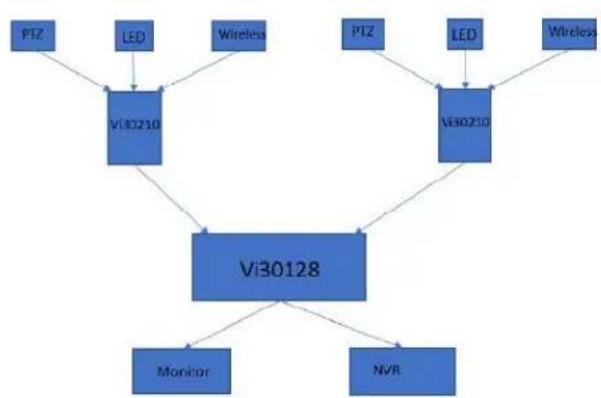
flowchart
graph TD
    PTZ --> Vi30210
    LED --> Vi30210
    Wireless --> Vi30210
    PTZ --> Vi30210
    LED --> Vi30210
    Wireless --> Vi30210
    Vi30128 --> Monitor
    Vi30128 --> NVR
Single Headend Configuration

flowchart
graph TD
    A["Vi30210"] --> B["Monitor"]
    A --> C["NV8"]
    A --> D["Alum 1"]
    A --> E["Alum 2"]
    A --> F["V10480 Power supply 1"]
    A --> G["V10480 Power supply 2"]
    A --> H["Camera"]
    A --> I["LCD"]
    A --> J["Wireless"]
Installing the Switch
Selecting a Site
The switch can be mounted using DIN Rail mounts equipment or operated using the rack mount kit or on a flat surface. Be sure to follow the guidelines below when choosing a location.
The site should:
• Be at the center of all the devices that you want to link and near a power outlet.
- Be able to maintain its temperature within -30^ to 70C (-30°C to 158°F) and its humidity within 10% to 90% , non-condensing.
- Be accessible for installing, cabling, and maintaining the devices.
- Allow the status LEDs to be clearly visible.
Make sure the twisted-pair Ethernet cable is always routed away from power lines, radios, transmitters, or any other electrical interference.
Make sure that Vi30210 is connected to a separate grounded power supply that provides 100 to 240 VAC, 50 to 60 Hz.
Make sure the power supply you are using provides the required power for your connected devices.
Ethernet Cabling
To ensure proper operation when installing the switch into a network, make sure that the current cables are suitable for 100BASE-TX or 1000BASE-T operation.
Check the following criteria against the current installation of your network:
Cable type: Unshielded twisted pair (UTP) or shielded twisted pair (STP) cable with RJ-45 connectors; Category 5 or Category 5e with a maximum length of 100 meters is recommended 100BASE-TX, and Category 5e or 6 with a maximum length of 100 meters is recommended for 1000BASE-T.
Protection from radio frequency interference emissions.
Electrical surge suppression.
Separation of electrical wires and data-based network wiring.
Safe connections with no damaged cables, connectors, or shields.
RJ-45 Connections
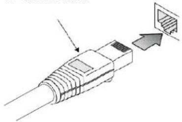
natural_image
Diagram of a USB connector with an arrow indicating insertion or disassembly (no text or symbols present)SFP Transceiver

natural_image
Diagram showing a device being inserted into a rack, with no visible text or symbolsEquipment Checklist
Package Contents
After unpacking the switch, please check the contents to make sure you have received all of the components. Also, make sure you have all other necessary installation equipment before beginning the installation process.
• Vi30210 GbE Management Switch
• Din Rail/ wall Adaptor
i
NOTE: Please notify your sales representative immediately if any of the aforementioned items are missing or damaged.

WARNING: The mini-GBICs are Class 1 laser devices. Avoid direct eye exposure to the beam coming from the transmit port.
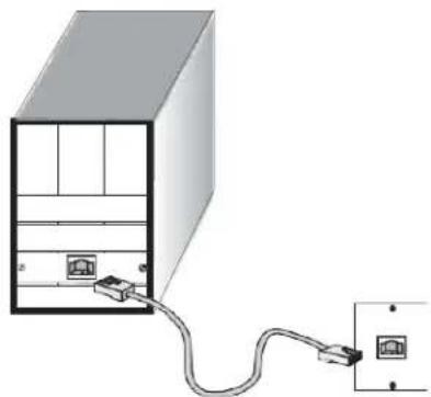
DIN Rail Mounting

natural_image
Pure electrical circuit lines without any symbolsLocate the mounting holds on the rear of the cabinet

natural_image
3D rendered image of a gray metal bracket with two circular holes (no text or symbols)Use the included mount screws to attach the DIN Rail mount to the rear of the cabinet

natural_image
Metallic rectangular panel with two circular holes, no visible text or symbolsWall Mounting and Desktop Mounting

natural_image
3D rendering of a black rectangular electronic component with ribbed top and mounting base (no visible text or symbols)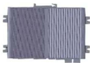
natural_image
Exterior view of a rectangular industrial heat exchanger or cooling unit (no signage or text visible)Insert the four tabs as shown. Secure the Vi30210 to a flat surface.
Installing an Optional SFP Transceiver
You can install or remove a mini-GBIC SFP from a mini-GBIC slot without having to power off the switch. Use only manufacture mini-GBIC.

NOTE:
- The mini-GBIC slots are shared with the two 10/100/1000Base-T RJ-45 ports. If a mini-GBIC is installed in a slot, the associated RJ-45 port is disabled and cannot be used.
• The mini-GBIC ports operate only at full-duplex. Half-duplex operation is not supported.
• Ensure the network cable is NOT connected when you install or remove a mini-GBIC.

CAUTION:
Use only supported genuine manufacture mini- GBICs with your switch. Non-manufacture mini-GBIC might have compatibility issues, and may result in product malfunction. SFPs should conform to the MSA standards.
Inserting an SFP Transceiver into a Slot

natural_image
Diagram showing a device being inserted into a rack, with no visible text or symbolsDescription
SFP Slots Support the following SFPs- SFPs must match the Fiber Cable
1000Base-SX GE SFP Fiber Module, LC Multi-Mode 850nm
1000Base-SX GE SFP Fiber Module, LC Multi-Mode 1310nm 2km
1000Base-LX GE SFP Fiber Module, LC Single-Mode 10km
1000Base-LX GE SFP Fiber Module, LC Single-Mode 30km
1000Base-LX GE SFP Fiber Module, LC Single-Mode 50km
1000Base-LX GE SFP Fiber Module, LC Single-Mode 50km
1000Base-LX GE SFP Fiber Module, Bidi LC Single-Mode 10km, 1310nm
1000Base-LX GE SFP Fiber Module, Bidi LC Single-Mode 10km, 1550nm
1000Base-LX GE SFP Fiber Module, Bidi LC Single-Mode 20km, 1550nm
1000Base-LX GE SFP Fiber Module, Bidi LC Single-Mode 20km, 1310nm
100Base-FX FE SFP Fiber Module, LC Multi-Mode, 850nm
100Base-FX FE SFP Fiber Module, LC Single-Mode 20km, 1310nm
2500Base-LX SFP Fiber Module, LC - Single Mode 20Km, 1310nm

CAUTION:
Differences in manufacturers may result in different performance and reporting statuses.
To Install an SFP Transceiver, Do the Following:
Step1: Consider the network and cabling requirements to select an appropriate SFP transceiver type.
Step2: Insert the transceiver with the optical connector facing outward and the slot connector facing down. Note that SFP transceivers are keyed so they can only be installed in one orientation.
Step3: Slide the SFP transceiver into the slot until it clicks into place.
i
Note: SFP transceivers are not provided in the switch package.
Connecting to the Console Port
The RJ-45 serial port on the switch's front panel is used to connect to the switch for out-of-band console configuration. The command-line-driven configuration program can be accessed from a terminal or a PC running a terminal emulation program. The pin assignments used to connect to the serial port are provided in the following table.

RJ-45pin Assignment
This RJ-45 connector provides an RS-232 DCE (data communication equipment) asynchronous serial connection for local management

| Pin | Ref | Definition | Direction |
| 3 | RxD | Receive Data | Out towards DTE |
| 6 | TxD | Transmit Data | In from DTE |
| 5 | SG | Signal Ground | na |
Serial Cable wiring
Switch's 8-Pin Serial Port
Null Modem
PC's 9-Pin DTE Port
This DB9F to RJ-45 cable provides a connection for the RS-232. This cable is used between this device and the serial port of terminal.
to PC COM Port

| Pins | Ref. | Definition | Direction | |
| DB9 | RJ-45 | |||
| 2 | 3 | RxD | Receive Data | Outthe device towards DTE |
| 3 | 6 | TxD | Transmit Data | In the device from DTE |
| 5 | 5 | SG | Signal Ground | na |

Serial Cable Wiring: Note no other connections are required.
Plug in the Console Port

natural_image
Illustration of a light blue Ethernet connector attached to a black device labeled 'CONSOLE' (no additional text or symbols)The serial port's configuration requirements are as follows:
• Default Baud Rate: 115,200 bps
• Character Size: 8 Characters
- Parity: None
- Stop Bit: One
- Data Bits: 8
- Flow Control: None
Making Network Connections
Connecting Network Devices
The switch is designed to be connected to 10, 100, or 1000Mbps network cards in PCs and servers, as well as, to other switches and hubs. It may also be connected to remote devices using optional SFP transceivers.
Each device requires an unshielded twisted-pair (UTP) cable with RJ-45 connectors at both ends. Use Category or c 5e, or 6 cables for 1000BASE-T connections, and Category 5 or better for 100BASE-TX connections.
Cabling Guidelines- UTP Copper Cabling
The RJ-45 ports on the switch support automatic MDI/MDI-X pin-out configuration, so you can use standard straight-through or cross twisted-pair cables to connect to any other network device (PCs, servers, switches, routers, or hubs).
See Appendix B for further information on cabling.

CAUTION: Do not plug a phone jack connector into an RJ-45 port. This will damage the switch. Use only twisted-pair cables with RJ-45 connectors that conform to FCC standards.
Connecting to PCs, Servers, Hubs and Switches
Step 1: Attach one end of a twisted-pair cable segment to the device's RJ-45 connector.
natural_image
Diagram of a server rack connected to an electrical outlet via cable (no text or symbols)Making Twisted-Pair Connections
Step 2: If the device is a network card and the switch is in the wiring closet, attach the other end of the cable segment to a modular wall outlet that is connected to the wiring closet. See the section "Network Wiring Connections." Otherwise, attach the other end to an available port on the switch.
Make sure each twisted pair cable does not exceed 100 meters (328 ft) in length.

NOTE: Avoid using flow control on a port connected to a hub, unless it is actually required to solve a problem. Otherwise, back pressure jamming signals may degrade overall performance for the segment attached to the hub.
Step 3: The green LED notes both link and activity. When the link is 1G the LED will be amber.
Network Wiring Connections
Today, the punch-down block is an integral part of many of the newer equipment racks. It is actually part of the patch panel. Instructions for making connections in the wiring closet with this type of equipment are as follows.
Step 1: Attach one end of a patch cable to an available port on the switch, and the other end to the patch panel.
Step 2: If it's not already in place, attach one end of a cable segment to the back of the patch panel where the punch-down block is located and the other end to a modular wall outlet.
Step 3: Label the cables to simplify future troubleshooting. See "Cable Labeling and Connection Records" on page 29.
Making Fiber Port Connections
An optional Gigabit SFP transceiver can be used as a backbone connection between switches, or as a connection to a high-speed server.
Each single-mode fiber port requires 9/125 micron single-mode fiber optic cable with an LC connector at both ends. Each multimode fiber optic port requires 50/125- or 62.5/125-micron multimode fiber optic cabling with an LC connector at both ends.

WARNING: This switch uses lasers to transmit signals over a fiber optic cable. The lasers are inherently eye-safe in normal operation. However, the user should never look directly at a transmit port when it is powered on.

WARNING: Considering safety, when selecting a fiber SFP device, please make sure that it can function at a temperature that is not less than the recommended maximum operating temperature of the product. You must also use an approved laser SFP transceiver.
Step 1: Remove and keep the LC port's rubber plug. When it's not connected to a fiber cable, the rubber plug should be replaced to protect the optics.
Step 2: Check that the fiber terminators are clean. You can clean the cable plugs by wiping them gently with a clean tissue or cotton ball moistened with a little ethanol. Dirty fiber terminators on fiber optic cables will impair the quality of the light transmitted through the cable and lead to degraded performance on the port.
Step 3: Connect one end of the cable to the LC port on the switch and the other end to the LC port on the other device. Since LC connectors are keyed, the cable can be attached in only one orientation.
Step 4: As a connection is made, check the Link LED on the switch corresponding to the port to be sure that the connection is valid.
The fiber optic ports operate at 1 Gbps. The maximum length for fiber optic cable operating at Gigabit speed will depend on the fiber type as listed under "1000 Mbps Gigabit Ethernet Collision Domain" on page 27.
Connectivity Rules
1000Base-T Cable Requirements
When adding hubs to your network, please note that because switches break up the path for connected devices into separate collision domains, you should not include the switch or connected cabling in your calculations for cascade length involving other devices.
All Category 5 UTP cables that are used for 100BASE-TX connections should also work for 1000BASE-T, provided that all four wire pairs are connected. However, it is recommended that for all critical connections, or any new cable installations,
Category 5e or Category 6 cable should be used. The Category 5e and 6 specifications include test parameters that are only recommendations for
Category 5. Therefore, the first step in preparing the existing Category 5 cable to run 1000BASE-T is to make sure that it complies with the IEEE 802.3-2005 standards.
1000 Mbps Gigabit Ethernet Collision Domain
| Cable Type | Maximum Cable Length | Connector |
| Category 5, 5e or 6 100-ohm UTP or STP | 100.m (328 ft) | RJ-45 |
| Fiber Size | Fiber Bandwidth | Maximum Cable Length | Connector |
| 62.5/125 micron | 160 MHz/km | 220 m (722 ft) | LC |
| multimode fiber | 200 MHz/km | 275 m (902 ft) | LC |
| 50/125 micron | 400 MHz/km | 500 m (1641 ft) | LC |
| multimode fiber | 500 MHz/km | 550 m (1805 ft) | LC |
Table 6: Maximum 1000BASE-SX Gigabit Fiber Cable Lengths
| Fiber Size | Fiber Bandwidth | Maximum Cable Length | Connector |
| 9/125 micron single-mode fiber 1310nm | N/A | 10km (6.2 miles) | LC |
| 9/125 micron single-mode fiber 1550nm | N/A | 30km (18.64 miles) | LC |
| 50km (31.06 miles) | LC |
Maximum 1000BASE-LX/LHX/XD/ZX Gigabit Fiber Cable Length
| Fiber Size | Fiber Bandwidth | Maximum Cable Length | Connector |
| Single-mode TX-1310nm RX-1550nm | N/A | 20km (12.42miles) | BIDI LC |
| Single-mode TX-1550nm RX-1310nm | N/A | 20km (12.42miles) | BIDI LC |
Maximum 1000BASE-LX Single Fiber Gigabit Fiber Cable Length
100 Mbps Fast Ethernet Collision Domain
| Cable Type | Maximum Cable Length | Connector |
| Category 5, 5e or6 100-ohm UTP or STP | 100.m (328 ft) | RJ-45 |
Maximum Fast Ethernet Cable Lengths
Cable Labeling and Connection Records
When planning a network installation, it is essential to label the opposing ends of cables and record where each cable is connected. This will allow the user to easily locate inter-connected devices, isolate faults, and change the topology without the need for unnecessary time consumption.
To best manage the physical implementations of your network, follow these guidelines:
• Clearly label the opposing ends of each cable.
• Use your building's floor plans to draw a map of the locations of all network-connected equipment.
For each piece of equipment, identify the devices to which it is connected.
• Note the length of each cable and the maximum cable length supported by the switch ports.
• For ease of understanding, use a location-based key when assigning prefixes to your cable labeling.
• Use sequential numbers for cables that originate from the same equipment.
• Differentiate between racks by naming accordingly.
- Label each separate piece of equipment.
• Display a copy of your equipment map, including keys to all abbreviations at each equipment rack.
Basic Troubleshooting Tips
Most problems are caused by the following situations. Check for these items first when starting your troubleshooting:
Connecting to devices that have a fixed full-duplex configuration.
The RJ-45 ports are configured as "Auto". When connecting to the attached devices, the switch will operate in one of two ways to determine the link speed and the communication mode (half-duplex or full-duplex):
- If the connected device is also configured to "Auto", the switch will automatically negotiate both link speed and communication mode.
- If the connected device has a fixed configuration (e.g. 100Mbps at half or full duplex), the switch will automatically sense the link speed but will default to a communication mode of half-duplex.
- Because the series Vi30210 behave in this way (in compliance with the IEEE802.3 standard), if a device connected to the switch has a fixed configuration at full-duplex, the device will not connect correctly to the switch. The result will be high error rates and very inefficient communications between the switch and the device.
• Make sure all devices connected to the Vi30210 are configured to auto-negotiate or are configured to connect at half-duplex (e.g. all hubs are configured this way). - Faulty or lose cables. Look for loose or faulty connections. If they appear to be OK, make sure the connections are snug. If that does not correct the problem, try a different cable.
- Non-standard cables. Non-standard and miswired cables may cause network collisions and other network problems, and can seriously impair network performance. Use a new correctly-wired cable for pin-outs and correct cable wiring. A category 5 cable tester is a recommended tool for every 100Base-TX and 1000Base-T network installation.
- Improper Network Topologies. It is important to make sure you have a valid network topology. If you no longer experience the problems, the new topology is probably at fault. In addition, you should make sure that your network topology contains no data path loops.
- Check the port configuration. A port on your switch may not be operating as you expect because it has been put into a "blocking" state by the Spanning Tree, the GVRP (automatic VLANs), or the LACP (automatic trunking). Note that the normal operation of the Spanning Tree, GVRP, and LACP features may put the port into a blocking state. Or, the port just may have been configured as
- "Disabled" through software.
Basic Troubleshooting Chart
| Symptom | Action |
| POWER LED is Off | ○ Check connections between the switch, the power cord, and the wall outlet.○ Contact your dealer for assistance. |
| Link LED is Off | ○ Verify that the switch and attached device are powered on.○ Be sure the cable is plugged into the switch and corresponding device.○ If the switch is installed in a rack, check the connections to the punch-down block and the patch panel.○ Verify that the proper cable type is used and its length does not exceed specified limits.○ Check the adapter on the attached device and cable○ connections for possible defects. Replace the defective adapter or cable if necessary. |
If the power indicator does not turn on when the power cord is plugged in, you may have a problem with the power outlet, power cord, or internal power supply. However, if the unit powers off after running for a while, check for loose power connections, power losses, or surges at the power outlet. If you still cannot isolate the problem, the internal power supply may be defective. Verify that all system components have been properly installed. If one or more components appear to be malfunctioning (e.g. the power cord or network cabling), test them in an alternate environment where you are sure that all the other components are functioning properly.
You can access the management agent in the switch from anywhere within the attached network using Telnet, a web browser. However, you must first configure the switch with a valid IP address, subnet mask, and default gateway. If you have trouble establishing a link to the management agent, check to see if you have a valid network connection. Then verify that you've entered the correct IP address. Also, be sure the port that you are connecting to the switch has not been disabled. If it has not been disabled, then check the network cabling that runs between your remote location and the switch.

IP Addressing: In order to access the Vi30210's GUI, your connected computer must be on the same network as the switch. As the default IP address is 192.168.1.130, the computer you use can be addressed as 192.168.1.xxx (any number except (130).
Power and Cooling Problems
Installation
The Vi30210 can operator under high temperature ranging from -30C to 70C. The unit is not weatherproof and requires installation in weatherproof housing. Consideration must be given to the potential internal temperature within the housing that will affect operations. The Vi30210 does provide operation settings which monitor the switches internal temperature and will affect individual port shut downs based on the actual settings. It is recommended these settings not exceed 115C.
Cables
Twisted-Pair Cable and Pin Assignment
For 10/100BASE-TX connections, the twisted-pair cable must have two pairs of wires. For 1000BASE-T connections, the twisted-pair cable must have four pairs of wires. Each wire pair is identified by two different colors. For example, one wire might be green and the other, green with white stripes. Also, an RJ-45 connector must be attached to both ends of the cable.

CAUTION: DO NOT plug a phone jack connector into any RJ-45 port. Use only twisted-pair cables with RJ-45 connectors that conform with FCC standards.

CAUTION: Each wire pair must be attached to the RJ-45 connectors in a specific orientation.
The figure below illustrates how the pins on the RJ-45 connector are numbered. Be sure to hold the connectors in the same orientation when attaching the wires to the pins.

natural_image
Illustration of two Ethernet connectors with labeled pins (no text or symbols beyond labels)Figure 19: RJ-45 Connector Pin Numbers
10BASE-T/100Base-Tx Pin Assignments
Use unshielded twisted-pair (UTP) or shielded twisted-pair (STP) cable for RJ-45 connections: 100-ohm Category 3 or better cable for 10 Mbps connections, or 100-ohm Category 5 or better cable for 100 Mbps connections. Also, be sure that the length of any twisted-pair connection does not exceed 100 meters (328 feet).
The RJ-45 ports on the switch base unit support automatic MDI/MDI-X operation, so you can use straight-through cables for all network connections to PCs or servers, or to other switches or hubs. In straight-through cable, pins 1, 2, 3, and 6, at one end of the cable, are connected straight through to pins 1, 2, 3, and 6 at the other end of the cable. When using any RJ-45 port on this switch, you can use either a straight-through or crossover cable.
| Pin | MDI Signal Name | MDI-X Signal Name |
| 1 | Transmit Data plus (TD+) | Receive Data plus (RD+) |
| 2 | Transmit Data minus (TD-) | Receive Data minus (RD-) |
| 3 | Receive Data plus (RD+) | Transmit Data plus (TD+) |
| 6 | Receive Data minus (RD-) | Transmit Data minus (TD-) |
| 4,5,7,8 | Not used | Not used |

NOTE: The "+" and "-" signs represent the polarity of the wires that make up each wire pair.
EIA/TIA 568B RJ-45 Wiring Standard
Straight-Through Wiring
If the twisted-pair cable is to join two ports and only one of the ports has an internal crossover (MDI-X), the two pairs of wires must be straight-through (when auto-negotiation is enabled for any RJ-45 port on this switch, you can use either straight-through or crossover cable to connect to any device type).
You must connect all four wire pairs as shown in the following diagram to support Gigabit Ethernet.
EIA/TIA 568B RJ-45 Wiring Standard 10/100BASE-TX
Straight-through Cable
Figure 20: Straight-through Wiring
If the twisted-pair cable is to join two ports and either both ports are labeled with an "X" (MDI-X) or neither port is labeled with an "X" (MDI), a crossover must be implemented in the wiring (when auto-negotiation is enabled for any RJ-45 port on this switch, you can use either straight-through or crossover cable to connect to any device type).
You must connect all four wire pairs as shown in the following diagram to support Gigabit Ethernet
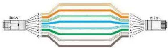
Crossover Wiring
10/100BASE-TX Crossover Cable
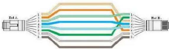
flowchart
graph LR
    A["End A"] --> B["1"]
    A --> C["2"]
    A --> D["3"]
    A --> E["4"]
    A --> F["5"]
    A --> G["6"]
    A --> H["7"]
    A --> I["8"]
    J["End B"] --> K["1"]
    J --> L["2"]
    J --> M["3"]
    J --> N["4"]
    J --> O["5"]
    J --> P["6"]
    J --> Q["7"]
    J --> R["8"]
Figure 21: Crossover Wiring
1000Base-T Pin Assignments
If your existing Category 5 installation does not meet one of the test parameters for 1000Base-T, there are three measures that can be applied to try and correct the problem:
Replace any Category 5 patch cables with high-performance Category 5e or Catgory 6 cables. Reduce the number of connectors used in the link.
Reconnect some of the connectors in the link.
1000BASE-T MDI and MDI-X Port Pin-Out
All 1000BASE-T ports support automatic MDI/MDI-X operation, so you can use straight-through cables for all network connections to PCs or servers, or to other switches or hubs.
The table below shows the 1000BASE-T MDI and MDI-X port pin outs. These ports require that all four pairs of wires be connected. Note that for 1000BASE-T operation, all four pairs of wires are used for both transmit and receive.
Use 100-ohm Category 5, 5e, or 6 unshielded twisted-pair (UTP) or shielded twisted-pair (STP) cable for 1000BASE-T connections. Also be sure that the length of any twisted-pair connection does not exceed 100 meters (328 ft).
| Pin | MDI Signal Name | MDI-X Signal Name |
| 1 | Bi-directional Pair A Plus (BI_DA+) | Bi-directional Pair B Plus (BI_DB+) |
| 2 | Bi-directional Pair A Minus (BI_DA-) | Bi-directional Pair B Minus (BI_DB-) |
| 3 | Bi-directional Pair B Plus (BI_DB+) | Bi-directional Pair A Plus (BI_DA+) |
| 4 | Bi-directional Pair C Plus (BI_DC+) | Bi-directional Pair D Plus (BI_DD+) |
| 5 | Bi-directional Pair C Minus (BI_DC-) | Bi-directional Pair D Minus (BI_DD-) |
| 6 | Bi-directional Pair B Minus (BI_DB-) | Bi-directional Pair A Minus (BI_DA-) |
| 7 | Bi-directional Pair D Plus (BI_DD+) | Bi-directional Pair C Plus (BI_DC+) |
| 8 | Bi-directional Pair D Minus (BI_DD-) | Bi-directional Pair C Minus (BI_DC-) |
(NEXT), and Far-End Crosstalk (FEXT). This cable testing information is specified in the ANSI/TIA/EIA-TSB-67 standard. Additionally, cables must also pass test
parameters for Return Loss and Equal-Level Far-End Crosstalk (ELFEXT). These tests are specified in the ANSI/TIA/EIA-TSB-95 Bulletin, "The Additional Transmission Performance Guidelines for 100 Ohm 4-Pair Category 5 Cabling.

NOTE: That when testing your cable installation, be sure to include all patch cables between switches and end devices.
Fiber Standards
Important Note: Fiber SFPs have no standards regarding interface with network switches with the exception of the Multi standard Agreement (MSA) with is limited to the physical interface between the SFP and a switch port. Data transmission may require adjusting port bandwidth settings on your switch.
When installing SFP match certain the SFP matches the installed fiber and are the same on both ends of the cable
The International Telecommunication Union (ITU-T) has standardized various fiber types for data networks. These are summarized in the following table.
Fiber Standards
| ITU-T Standard | Description | Application |
| G.651 | Multimode Fiber50/125-micron core | Short-reach connections in the 1300- nm or 850-nm band. |
| G.652 | Non-Dispersion-Shifted FiberSingle-mode, 9/125- micron core | Longer spans and extended reach. Optimized for operation in the 1310- nm band, but can also be used in the 1550-nm band. |
| G.652.C | Low Water Peak Non- Dispersion-Shifted Fiber Single-mode, 9/125-micron core | Longer spans and extended reach. Optimized for wavelength-division multiplexing (WDM) transmission across wavelengths from 1285 to 1625 nm. The zero-dispersion wavelength is in the 1310-nm region. |
| G.653 | Dispersion-Shifted FiberSingle-mode, 9/125- micron core | Longer spans and extended reach. Optimized for operation in the region from 1500 to 1600-nm. |
| G.654 | 1550-nm Loss- Minimized FiberSingle-mode, 9/125- micron core | Extended long-haul applications. Optimized for high-power transmission in 1500 to 1600-nm region, with low loss in the 1550-nm band. |
| G.655 | Non-Zero Dispersion- Shifted FiberSingle-mode, 9/125- micron core | Extended long-haul applications. Optimized for high-power dense wavelength-division multiplexing (DWDM) operation in the region from 1500 to 1600-nm. |
Specifications
Physical Characteristics
| Ports | 2 100/1000Mbps SFP Fiber ports2 GbE Combo Port TP/ (100/1000M) SFP |
| Network Interface | Ports 1-8: RJ-45 Connector10BASE-T: RJ-45 (100-ohm, UTP cable; Category 3 or better)100BASE-TX: RJ-45 (100-ohm, UTP cable; Category 5 or better)1000BASE-T: RJ-45 (100-ohm, UTP or STP cable;Category 5, 5e or 6)*Maximum Cable Length - 100 m (328 ft)Ports 9-10: RJ-45 connector/ (100/1000M) SFPPorts 11, 12 – fiber connections in combo with copper ports 9 and 10. |
Buffer Architecture 1392KB on-chip frame buffer
Aggregate Bandwidth 20 Gbps
| Switching Database LEDs | 8K MAC address entries System: POWER TP Port: status (LINK/ACT), 10/100/1000M |
| SFP Port: status (LINK/ACT/SPD), 100/1000M |
| Weight | 1.9 lbs. |
| Size | 4 3/8" x 2" x 6 5/8" |
| Temperature | Operating: -30°C to 70°C (-22°F to 158°F) |
| Humidity | Operating: 5% to 90% (non-condensing) |
| Power Input | Not to exceed 480 watts @ 57VDC |
| Power Supply | External DC input |
| Power Consumption | 20W maximum |
Switch Features
| Forwarding Mode | Store-and-forward |
| Throughput | 35.712Mpps |
| Flow Control | Full-Duplex: IEEE 802.3xHalf-Duplex: Back pressure |
Management Features
| In-Band Management | SSH/SSL, Telnet, SNMP, or HTTP |
| Out-Of-Band | RS-232 (RJ-45) console port |
| Management | |
| Software Loading | HTTP, TFTP in-band, Console out-of-band |
Standards
IEEE 802.3 => 10Base-T Ethernet (Twisted-pair Copper)
IEEE 802.3u => 100Base-TX Ethernet (Twisted-pair Copper)
IEEE 802.3ab => 1000Base-TX Ethernet (Twisted-pair Copper) IEEE 802.3z => 1000Base-X Ethernet
IEEE 802.3x => Flow Control Capability ANSI/IEEE 802.3 => Auto-negotiation
IEEE 802.1Q => VLAN
IEEE 802.1p => Class of Service IEEE 802.1X => Access Control IEEE 802.1D => Spanning Tree
IEEE 802.1w => Rapid Spanning Tree
IEEE 802.1s => Multiple Spanning Tree
IEEE 802.3ad => ink Aggregation Control Protocol (LACP) IEEE 802.1AB => Link Layer Discovery Protocol (LLDP)
IEEE 802.3at/af => Power Over Ethernet (PoE)
Emissions
EN55022 (CISPR 22) Class A EN 61000-3
FCC Class A
CE Mark
Immunity
EN 61000-4-2/3/4/5/6/8/11
EN 55024
Compliances
| 10Base-T | IEEE 802.3 specification for 10 Mbps Ethernet over two pairs of Category 3, 4, or 5 UTP cable. |
| 100Base-T | IEEE 802.3u specification for 100 Mbps Ethernet over two pairs of Category 5 UTP cable. |
| 1000Base-LH | Specification for long-haul Gigabit Ethernet over two strands of 9/125 micron core fiber cable. |
| 1000Base-LX | IEEE 802.3z specification for Gigabit Ethernet over two strands of 50/125, 62.5/125, or 9/125-micron core fiber cable. |
| 1000Base-SX | IEEE 802.3z specification for Gigabit Ethernet over two strands of 50/125 or 62.5/125-micron core fiber cable. |
| 1000Base-T | IEEE 802.3ab specification for Gigabit Ethernet over 100-ohm Category 5, 5e, or 6 twisted-pair cable (using all four wire pairs). |
| Auto-Negotiation | Signaling method allowing each node to select its optimum operational mode (e.g. speed and duplex mode) based on the capabilities of the node to which it is connected. |
| Bandwidth | The difference between the highest and lowest frequencies available for network signals. Also synonymous with wire speed, the actual speed of the data transmission along the cable. |
| Collision Domain | Single CSMA/CD LAN segment. |
| CSMA/CD | CSMA/CD (Carrier Sense Multiple Access/Collision Detect) is the communication method employed by Ethernet, Fast Ethernet, and Gigabit Ethernet. |
| End Station | A workstation, server, or other device that does not forward traffic. |
| Ethernet | A network communication system developed and standardized by DEC, Intel, and Xerox, were using baseband transmission, CSMA/CD access, logical bus topology, and coaxial cable. The successor IEEE 802.3 standard provides for integration into the OSI model and extends the physical layer and media with repeaters and implementations that operate on fiber, thin coax, and twisted-pair cable. |
| Fast Ethernet | A 100 Mbps network communication system based on Ethernet and the CSMA/ CD access method. |
| Full Duplex | Transmission method that allows two network devices to transmit and receive concurrently, effectively doubling the bandwidth of that link. |
| Gigabit Ethernet | A 1000 Mbps network communication system based on Ethernet and the CSMA/ CD access method. |
| IEEE | Institute of Electrical and Electronic Engineers. |
| IEEE 802.3 | Defines carrier sense multiple access with collision detection (CSMA/CD) access method and physical layer specifications. |
| IEEE 802.3AB | Defines CSMA/CD access method and physical layer specifications for 1000BASE-T Gigabit Ethernet (now incorporated in IEEE 802.3-2005). |
| IEEE 802.3U | Defines CSMA/CD access method and physical layer specifications for 100BASE- TX Fast Ethernet (now incorporated in IEEE 802.3- 2005). |
| IEEE 802.3X | Defines Ethernet frame start/stop requests and timers used for flow control on full-duplex links (now incorporated in IEEE 802.3-2005). |
| IEEE 802.3Z | Defines CSMA/CD access method and physical layer specifications for 1000BASE Gigabit Ethernet (now incorporated in IEEE 802.3-2005). |
| IEEE 802.3at/af | Defines Power Over Ethernet is used to transmit electrical power, PoE IEEE 802.3af (Class 4 PDs limited to 15.4W), PoE++ IEEE 802.3at (Class 4 PDs limited to 30W). |
| Lan Segment | Separate LAN or collision domain. |
| LED | Light emitting diode used for monitoring a device or network condition. |
| Local Area Network (LAN) | A group of interconnected computer and support devices. |
| Media Access Control (MAC) | A portion of the networking protocol that governs access to the transmission medium, facilitating the exchange of data between network nodes. |
| MIB | An acronym for Management Information Base. It is a set of database objects that contain information about the device. |
| Modal Bandwidth | Bandwidth for multimode fiber is referred to as modal bandwidth because it varies with the modal field (or core diameter) of the fiber.Modal bandwidth is specified in units of MHz per km, which indicates the amount of bandwidth supported by the fiber for a one km distance. |
| Network Diameter | Wire distance between two end stations in the same collision domain. |
| RJ-45 Connector | A connector for twisted-pair wiring. |
| Switched Ports | Ports that are on separate collision domains or LAN segments. |
| TIA | Telecommunications Industry Association. |
| Transmission Control Protocol/Internet Protocol (TCP/IP) | Protocol suite that includes TCP as the primary transport protocol and IP as the network layer protocol. |
| User Datagram Protocol (UDP) | UDP provides a datagram mode for the packet-switched communications. It uses the IP as the underlying transport mechanism to provide access to IP-like services. UDP packets are delivered just like IP packets – connection- less data grams that may be discarded before reaching their targets. UDP is useful when TCP would be too complex, too slow, or just unnecessary. |
| UTP | Unshielded twisted-pair cable. |
| Virtual LAN (VLAN) | A Virtual LAN is a collection of network nodes that share the same collision domain regardless of their physical location or connection point in the network. A VLAN serves as a logical workgroup with no physical barriers, allowing users to share information and resources as though located on the same LAN. |
Warranty
Vigitron, Inc. guarantees that all Vigitron products ("Product"), if used in accordance with these instructions, will be free of defects in material and workmanship for a lifetime defined as the duration period of time until product end of life is announced.
After which, Vigitron will continue to provide warranty services for a period of 3 years. The period covering valid warranty will be determined by proof of purchase in the form of an invoice from an authorized Vigitron dealer.
Warranty will only be provided for as long as the original end-user purchaser owns the product. The warranty is not transferrable. At Vigitron's option, the defective product will be repaired, replaced, or substituted with a product of equal value. This warranty does not apply if in the judgment of Vigitron, Inc., the Product fails due to damage from shipment, handling, storage, accident, abuse, or misuse, or if it has been used or maintained not conforming to product manual instructions, has been modified, or serial number removed or defaced. Repair by anyone other than
Vigitron, Inc. or an approved agent will void this warranty. Vigitron, Inc. shall not under any circumstances be liable to any person for any incidental, indirect, or consequential damages, including damages resulting from use or malfunction of the product, loss of profits or revenues, or costs of replacement goods. The maximum liability of Vigitron, Inc. under this warranty is limited to the original purchase price of the product only.
Contact Information
Vigitron, Inc.
7810 Trade Street, Suite 100 San Diego, CA 92121
Phone: 858-484-5209
Fax: (858) 484-1205
www.vigitron.com
support@vigitron.com
GUI Header Controls

The house Icon returns the GUI to the home page which shows a graphical display of the Vi30210 and its active ports- Moving the curser over a port will displayed its name. Clicking on the port will show its detailed Statistics.
The Arrow icon will ask if you want to log out of the website
The Question icon will provide details on the page you are on
WEB Configuration
Chapter 1: Configuration Preparation
1.1 Access to Switch by WEB
Important Note: Your choice of Internet browser can affect your ability to access the switch and/or certain switch functions. If you experience these problems, please check the browser security settings.
Ensure it is coincident with the following requirements while accessing to the switch by Web browser.
- HTML Version 4.0
- HTTP Version 1.1
- JavaScript™ Version 1.5
Besides, ensure the operation of the main program file supports to access to the switch, and the computer is connecting to the network of a switch.
First time access to switch, you don't need additional configuration but access to switch directly by WEB if this the first time to use. Revise the IP address of your computer ethernet adapter to "192.168.1.xxx" there the last three digits are different from the Vi30210. The subnet mask is "255.255.255.0".
Open the WEB browser, enter the "192.168.1.130" in the address bar, note that "192.168.1.130" is the defaulted IP address of switch.
The dialog is appeared like picture 1 if you use Internet Explorer. Enter the account and passwords in the authenticated dialog, the original user name is "admin" and the password is "admin". Please distinguish the capital and small letter.

Picture 1: WEB Authentication Dialog.
Reset key – default function:
- Remove power
- Reconnect the power
- Within 10 seconds press and hold the reset button on the front panel
- The LED front panel lights will flash 4 times and the switch default settings will be restored
The browser will display the system information page if it's authenticated successfully. Like picture 2, 8 Ports with 2 combo fiber/copper switch.
These ports 9 and 10, 11 and 12 are combo ports. However, for set up they are labeled separately, either the copper or fiber port can be used but not both at the same time.
After Reset is complete, recheck your programming as some setting may need to be reprogrammed


System Information Page of Switch
WEB Page Introduction
Order, Guide, Configuration System Display, Top Control and etc.


This Is the Home button. Click it, the management page will return back the original one.


This's Logout button. After clicking "Confirm", you need to retype the account and passwords if WEB function is used again.

This Show Help button. It helps engineers to set the specification of devices. There's a specific page of each function set page. You can click it to display the function page anytime.
1.2 Guide

Note: The restricted user can't revise the device configuration but only visits the state. If they log in to the WEB, the other groups are disappeared but only the device state.
Port State Overview

The state information and configuration of the device are shown in the Configuration Display. You can change the details by clicking the list items.
1.3 Top Control
Auto-refresh □ Refresh
Achieving the Auto-refresh of Configuration Display is the vital function of Top Control. For example, you can monitor the port statistics continuously by selecting view firstly and clicking Auto-refresh later. The screen will auto-refresh 1/3s.
Click "Clear" button can clear. It's suggested that don't use the Auto-refresh function for it'll surely result in traffic unless it's connected in LAN directly.
After program is complete it must be saved to start up otherwise it power it lost settings will revert back to default.
To Save your programming use Maintenance>Configuration>Save startup.
Chapter 2: Monitor
2.1 System

System List
Click the system option group can open or close the list items.
2.1.1 Information Configuration
System Information Configuration
| System Contact | *** |
| System Name | *** |
| System Location | *** |
System Information Configuration
System Information
| System | |
| Contact | |
| Name | |
| Location | |
| Hardware | |
| MAC Address | 40-d8-56-1a-00-01 |
| Chip ID | ABC--888 |
| Software | |
| Software Version | CE |
| Software Date | 09-2019 |
| Acknowledgments | Details |
System Information State
A. System Contact: The textual identification of the contact person for this managed node, together with information on how to contact this person. The allowed string length is 0 to 255, and the allowed content is the ASCII characters from 32 to 126.
B. System Name: An administratively assigned name for this managed node. By convention, this is the node's fully-qualified domain name. A domain name is a text string drawn from the alphabet (A-Za-z), digits (0-9), minus sign (-). No space characters are permitted as part of a name. The first character must be an alpha character. And the first or last character must not be a minus sign. The allowed string length is 0 to 255.
C. System Location: The physical location of this node (e.g., telephone closet, 3rd floor). The allowed string length is 0 to 255, and the allowed content is the ASCII characters from 32 to 126.
2.1.2 IP
IP Configuration
| Mode | Host | |
| DNS Server 0 | NoDNS server | |
| DNS Server 1 | NoDNS server | |
| DNS Server 2 | NoDNS server | |
| DNS Server 3 | NoDNS server | |
| DNS Proxy | ||
IP Interfaces
| Delete | VLAN | DHCPv4 | IPv4 | DHCPv6 | IPv6 | ||||||
| Enable | Fallback | Current Lease | Address | Mask Length | Enable | Rapid Commit | Current Lease | Address | Mask Length | ||
| 1 | 0 | 192.758.1.130 | 24 | ||||||||
Add Interface
IP Routes
| Delete | Network | Mask Length | Gateway | Next Hop VLAN |
Add Route
Save Reset
Devise IP Configuration
IP Configuration
Mode: Mode: "Host" is defaulted, "Router" is optional.
DNS server 0-3 : This devise is controlled by accomplished DNS Name Resolution of switch. Named "No DNS server".
The followed modes are supported:
• From any DHCPv4 interfaces:
• Configured IPv4 or IPv6
• From this DHCPv4 interface
• From any DHCPv6 interfaces
• From this DHCPv6 interface
DNS Proxy: When it is started, the system will transmit the DNS request to the currently configured DNS server and plays a role as DNS parser to get back to the network client devise. Only the IPv4 DNS Proxy is supported at present.
IP Interfaces
- The specific steps for revising the defaulted IP address of devise can be referenced in the appendix 1.
IP Routes
- The specific steps for revising the defaulted IP address of devise can be referenced in the appendix 1.
2.1.3 NTP
Set NTP configuration, keep the time of device is synchronized with the network.
NTP Configuration
| Mode | Disabled |
| Server 1 | |
| Server 2 | |
| Server 3 | |
| Server 4 | |
| Server 5 |
| Save | Reset |
NTP Configuration
NTP Configuration
Mode) : Disabled or Enabled The disabled mode defaults.
Server1-5 : Provide the IPv4 or IPv6 address of an NTP server. IPv6 address is in 128-bit records represented as eight fields of up to four hexadecimal digits with a colon separating each field (:) . For example, 'fe80::215:c5ff: fe03:4dc7'. The symbol '-' is a special syntax that can be used as a shorthand way of representing multiple 16-bit groups of contiguous zeros, but it can appear only once. It can also represent a legally valid IPv4 address. For example, ':192.1.2.34'. In addition, it can also accept a domain name address.
Click the "Save" button to save; click the "Reset" button to reset.
2.1.4 Time
Time Zone Configuration
| Time Zone Configuration | ||
| Time Zone | (UTC-08.00) Pacific Time (US and Canada) | |
| Acronym | USA | ( 0 - 15 characters ) |
Daylight Saving Time Configuration
| Daylight Saving Time Mode | ||
| Daylight Saving Time | Non-Recurring | √ |
| Start Time settings | ||
| Month | Mar | √ |
| Date | 11 | √ |
| Year | 2019 | √ |
| Hours | 0 | √ |
| Minutes | 0 | √ |
| End Time settings | ||
| Month | Nov | √ |
| Date | 4 | √ |
| Year | 2019 | √ |
| Hours | 0 | √ |
| Minutes | 0 | √ |
| Offset settings | ||
| Offset | 60 | (1 - 1440) Minutes |
System Time
| system time | ||
| Date Format | dd/mm/yyyy | |
| Time Format | 24-hour | |
| System Date | 08-09-2019 | (dd-mm-yyyy) |
| System Time | 20:24:02 | (hh:mm:ss) |
| Save | Reset |
System Time
| system time | ||
| Date Format | mm/dd/yyyy | |
| Time Format | dd/mm/yyyy | |
| System Date | yyyy/mm/dd | |
| System Time | 23:15:00:00 | (hh:mm:ss) |
| 13:33:56 | ||
Devise Time Configuration Date Format
Select: None if not using NTP
| Time Zone Configuration | |
| Time Zone | None |
Select: Your local Time Zone if using NTP
Time Zone Configuration
Time Zone: It can be selected through drop-down menu. Acronym:0-15 characters are supported.
Daylight Saving Time Configuration: Daylight Saving Time has three modes as below.
o Disabled (Defaulted)
o Recurring
o Non-Recurring
System Time: Set the current local time or date and Date format of the system
o Date Format: Optional mm/dd/yyyy dd/mm/yyyy yyyy/mm/dd
o Time Format: Optional 24-hour or 12-hour.
o System Date: Display Date
o System Time: Display Time
Remarks: When setting the time and date, you must select the time zone column at (UTC) coordinated universal time.
Set the system clock and date based on the coordinated universal time in the 24-hour mode first then go to the 12-hour mode and confirm setting.
In the event of power loss, the time setting will revert to 24 hours
For additional NTP set up and accessing NTP services see Addendum 4
Time Zone Configuration
| Time Zone Configuration | |
| Time Zone | (UTC) Coordinated Universal Time |
System Log Configuration
| Server Mode | Enabled |
| Server Address | 192.168.1.12 |
| Syslog Level | Informational |
System Alarm Configuration
| Alarm Test | Alarm Enable | |
| Alarm output 1 | ○OFF ●ON | ○Disable ●Enable |
| Alarm output 2 | ○OFF ●ON | ○Disable ●Enable |
| Port | Alarm output 1 | Alarm output 2 |
| * | Link | Link |
| ALL | □ | □ |
| 1 | ☑ | ☑ |
| 2 | ☑ | ☑ |
| 3 | ☑ | ☑ |
| 4 | ☑ | ☑ |
| 5 | ☑ | ☑ |
| 6 | ☑ | ☑ |
| 7 | ☑ | ☑ |
| 8 | ☑ | ☑ |
| 9(11) | ☑ | ☑ |
| 10(12) | ☑ | ☑ |
| Save | Reset Alarm |
2.1.5 Log & Alarm
System Log
System Log Configuration
- Server Mode Indicates the server mode operation. When the mode operation is enabled, the syslog message will send out to syslog server. The syslog protocol is based on UDP communication and received on UDP port 514 and the syslog server will not send acknowledgments back sender since UDP is a connectionless protocol and it does not provide acknowledgments. The syslog packet will always send out even if the syslog server does not exist. Possible modes are:
a. Enabled: Enable server mode operation.
b. Disabled: Disable server mode operation.
-
Server Address Indicates the IPv4 host address of syslog server. If the switch provides DNS feature, it also can be a domain name.
-
Server Level: Indicates what kind of message will send to syslog server. Possible modes are:
a. Error: Send the specific messages which severity code is less or equal than Error (3).
b. Warning: Send the specific messages which severity code is less or equal than Warning (4).
c. Notice: Send the specific messages which severity code is less or equal than Notice (5).
d. Informational: Send the specific messages which severity code is less or equal than Informational (6).
System Alarm Configuration
The Vi30210 has two alarm outputs.
• To enable an alarm, select the Enable button
• To test an alarm, output select Alarm Test On
When selected:
• The selected alarm LED front panel will flash
• The selected relay will become active
Assigning the alarm
• Using the port alarm election either Alarm output 1 or 2 can be set to be active to the selected port
To Disable the Alarm
- Select Disable followed by Save
To Reset Alarm
• Select the port you want to reset that caused the alarm
- Press Reset Alarm
- Press Save
2.2. Green Ethernet

2.2.1 LED
Configure the LED intensity to reduce power consumption.
LED Power Reduction Configuration
LED Intensity Timers

Maintenance

LED Green Configuration Instance
LED intensity can be adjusted to a scale within a programable time period. In the above example, it is adjusted to 50% in the daytime while it drops down to 10% at night. The Maintenance will let it up to 100% within 10s if any errors are appeared (like link).
Note: If the intensity is 0% no LEDs for light
The default 20% and range 0-100% of Intensity can be required by setting start time and end time, and dropping down menu to choose. Click the "Add Time" button can add entry, "Save" can save, and "Reset" can restore defaulted configuration.
2.2.2 Port Power Savings
Port Power Savings Configuration

Port Configuration
Port Power Saving Configuration Dialog
- Port Power Saving Configuration:
- Optimize EEE for: The devise can be set for Optimize EEE, to achieving the best power saving or lowest traffic delays.
Power Enable the EEE function. This's defaulted setting.
o Latency: Disable the EEE function.
- Port Configuration
• ① Port: Devise port No,
- ② ActiPHY: t's working by reducing the port power without a connection. The port is started within a short time to check whether the ethernet cable is inserted. It also can save power for those ports that aren't cable-connected.
- ③ EEE (Green ethernet): EEE is a power saving option. It can reduce the power use under the condition of low or no traffic. EEE is developed by ieee802.3 az team of IEEE. It works to close the circuit when there's no traffic. All the circuits are started when one port gets data transmission. The started time for circuit is called arousing time. The arousing time is defaulted as 17-connected of 1Gbit and 30-connected speed. To make sure all the circuits can be supplied from the switch transceiver, EEE devise must be consistent with the value of arousing time. These devises can transmit the arousing time information via LLDP. The port is negotiated for 1G or 100Mbit full-duplex mode while EEE is working in the mode of autonegotiation. The EEE cannot be started and the related check box is gray when the port without EEE. When one port is closed to save power, the output traffic is saved in the buffer until the port is restarted. Some traffic will be happened while closing the port and upping, that'll save more power to transmit mass traffic if it can be buffered. The buffered traffic will be result in some transmission delay. Traffic that should not be blocked can be assigned in urgent queue to reduce delay, but still saving power generally.
- ⑤ EEE Emergency Queue: It minimizes the delay for a particular frame and then marks the queue as an emergency one by mapping a frame to a specific queue (using QOS). When an emergency queue obtains data transmission, the circuit will start immediately and the delay will be shortened to arousing time. Once the data is available, the queue set will activate the transmission of the frame. Otherwise, the queue will delay transmission until the Frame can be transmitted.
(Important Note: This function should not be used with connected devices that do not continuous transmit)
Thermal Protection
2.3 Thermal Protection
It is recommended that Thermal Temperature setting be limited to 115C
Thermal Protection Configuration Temperature settings for groups
| Group | Temperature | |
| 0 | 115 | °C |
| 1 | 111 | °C |
| 2 | 115 | °C |
| 3 | 115 | °C |
Port groups
| Port | Group | |
| 1 | 0 | √ |
| 2 | 0 | √ |
| 3 | 0 | √ |
| 4 | 0 | √ |
| 5 | Disabled | √ |
| 6 | Disabled | √ |
| 7 | Disabled | √ |
| 8 | Disabled | √ |
| 9 | Disabled | √ |
| 10 | Disabled | √ |
| 11 | Disabled | √ |
| 12 | Disabled | √ |
Save Reset

Thermal Protection
Thermal Protection Configuration Dialog
-
This page allows the user to check and configure the current settings to control thermal protection. The thermal protection is used to prevent the chip from overheating. When the temperature exceeds the configured thermal protection temperature, the port is closed to reduce power consumption. Ports can be arranged in different groups. Each group can be given a temperature to close the corresponding port.
-
Temperature limit is 115C higher temperatures will result in alarm being issued.
2.4 Ports

Port Configuration
Refresh
| Port | Description | Link | Speed | Adv Duplex | Adv speed | Flow Control | Maximum Frame Size | Excessive Collision Mode | Frame Length Check | ||||||
| Current | Configured | Fdx | Hdx | 10M | 100M | 1G | Enable | Curr Rx | Curr Tx | ||||||
| <> | √ | √ | √ | √ | √ | □ | 9000 | <> | □ | ||||||
| 1 | ● Down | Auto | √ | √ | √ | √ | √ | √ | □ | × | × | 9000 | Discard | □ | |
| 2 | ● Down | Auto | √ | √ | √ | √ | √ | √ | □ | × | × | 9000 | Discard | □ | |
| 3 | ● 100fdx | Auto | √ | √ | √ | √ | √ | √ | □ | × | × | 9000 | Discard | □ | |
| 4 | ● Down | Auto | √ | √ | √ | √ | √ | √ | □ | × | × | 9000 | Discard | □ | |
| 5 | ● Down | Auto | √ | √ | √ | √ | √ | √ | □ | × | × | 9000 | Discard | □ | |
| 6 | ● Down | Auto | √ | √ | √ | √ | √ | √ | □ | × | × | 9000 | Discard | □ | |
| 7 | ● Down | Auto | √ | √ | √ | √ | √ | √ | □ | × | × | 9000 | Discard | □ | |
| 8 | ● Down | Auto | √ | √ | √ | √ | √ | √ | □ | × | × | 9000 | Discard | □ | |
| 9 | ● 1Gfdx | Auto | √ | √ | √ | √ | √ | √ | □ | × | × | 9000 | Discard | □ | |
| 10 | ● Down | Auto | √ | √ | √ | √ | √ | √ | □ | × | × | 9000 | Discard | □ | |
| 11 | ● Down | Auto | √ | √ | √ | √ | √ | √ | □ | × | × | 9000 | □ | ||
| 12 | ● 1Gfdx Fiber | Auto | √ | √ | √ | √ | √ | √ | □ | × | × | 9000 | □ | ||
Save Reset
Ports Configuration
Port Configuration
A. Description: The description of the port. It is an ASCII string no longer than 256 characters.
B. Link: The current link state is displayed graphically. Green indicates the link is up and red that it is down.
C. Speed: The working modes of the configured ports are as below:
a. Disabled
b. Auto: The Auto mode is defaulted by system.
c. 10Mbps HDX
d. 10Mbps FDX100Mbps HDX
e. 100Mbps FDX
f. 1Gbps FDX
D. 2.5Gbps FDX. Only the fiber port can configure 2.5Gbps FDX.
E. Adv Duplex: When duplex is set as auto i.e auto negotiation, the port will only advertise the specified duplex as either Fdx or Hdx to the link partner. By default, port will advertise all the supported duplexes if the Duplex is Auto.
F. Adv speed: When Speed is set as auto i.e auto negotiation, the port will only advertise the specified speeds (10M100M1G) to the link partner. By default, port will advertise all the supported speeds if speed is set as Auto.
G. Flow Control: When Auto Speed is selected on a port, this section indicates the flow control capability that is advertised to the link partner.
When a fixed-speed setting is selected, that is what is used. The Current Rx column indicates whether pause frames on the port are obeyed, and the Current Tx column indicates whether pause frames on the port are transmitted. The Rx and Tx settings are determined by the result of the last Auto Negotiation.
Check the configured column to use flow control. This setting is related to the setting for Configured Link Speed. NOTICE: The 100FX standard doesn't support Auto Negotiation, so when in 100FX mode the flow control capabilities will always be shown as "disabled".
H. Maximum Frame Size: Enter the maximum frame size allowed for the switch port, including FCS. The range is 1518-9600 bytes.
a. Excessive Collision Mode Configure port transmit collision behavior.
b. Discard : Discard frame after 16 collisions (default).
c. Restart : Restart backoff algorithm after 16 collisions.
Frame Length Check: Configures if frames with incorrect frame length in the EtherType/Length field shall be dropped. An Ethernet frame contains a field EtherType which can be used to indicate the frame payload size (in bytes) for values of 1535 and below. If the EtherType/Length field is above 1535, it indicates that the field is used as an EtherType (indicating which protocol is encapsulated in the payload of the frame). If "frame length check" is enabled, frames with payload size less than 1536 bytes are dropped, if the EtherType/Length field doesn't match the actually payload length. If "frame length check" is disabled, frames are not dropped due to frame length mismatch. Note: No drop counters count frames dropped due to frame length mismatch.
2.5 DHCP
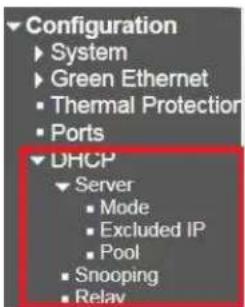
2.5.1 Server
2.5.1.1 Mode
DHCP Server Mode Configuration
Global Mode

VLAN Mode
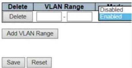
DHCP Sever Mode Configuration
• Global Mode: Global Mode: It is defaulted to Disabled Mode. Start Mode is Enable.
• VLAN Mode: It Indicates the VLAN range of the DHCP server that is enabled or disabled.
The first VLAN ID must be less than or equal to the second VLAN ID, but if the VLAN range contains only one VLAN ID, you can enter it into one or two VLAN IDs in the first VLAN ID.
On the other hand, you can follow the steps as below if you want to disable the existing VLAN range.
- Click "Add VLAN Range" to add a new entry.
- Enter the range of VLANs you want to disable in the VLAN Range field.
- Click "Save" to save or cancel. Then you will see the disable VLAN range is removed from the DHCP Server Mode Configuration page.
2.5.1.2 Excluded IP
DHCP Server Excluded IP Configuration
Excluded IP Address
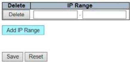
Picture17 : Clear IP Configuration Dialog
The defined IP range is the excluded IP address. The first excluded IP must be less than or equal to the second excluded IP.
But, if the IP range contains only one excluded IP, then you can enter it into the first and second excluded IPs, or both.
A. Click "Add IP Range" to add a new entry.
B. Click "Delete" can remove the entry.
C. Click "Save" to save or cancel configuration.
2.5.1.3 Pool
The DHCP Server will assign an IP address based on the Pool and pass the configuration parameters to the DHCP client.
DHCP Server Pool Configuration
Pool Setting

A. Click "Add New Pool" to enter a new entry. Click "Delete" can remove entry.
B. Enter the name of Pool. If you want to configure the details setting, you can click "Save" to save and then re-click Pool to enter the configuration page.
As shown below :
DHCP Pool Configuration
Pool

Setting

C. Type:
a. None: It indicates that the type of the Pool isn't defined
b. Network: It indicates that the Pool defines an IP address range, to serve multiple DHCP clients.
c. Host: It indicates the Pool Server of specific DHCP clients that identified by client identifier or hardware address.
d. It is not defined if "-"is shown.
D. IP: It displays the number of networks of the DHCP address Pool. It is not defined if "-"is shown.
E. Subnet Mask: It displays the subnet mask of DHCP address Pool. It is not defined if "-"is shown.
F. Lease Time: It displays the Lease Time of Pool.
2.5.2 Snooping
DHCP Snooping Configuration

Port Mode Configuration
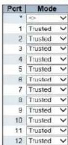

Snooping Configuration Dialog
DHCP Snooping Configuration
- Snooping Mode: Snooping Mode: It indicates DHCP Snooping Mode Operation. The devise is defaulted to Disabled mode, the Snooping Mode Operation is disabled. Enabled is the start mode. When DHCP Snooping Mode Operation is started, its request message will be forwarded to the trusted port, and only can get back from the trusted port.
Port Mode Configuration: It indicates Port Mode Configuration. Trusted is the defaulted mode, it configures the port to the trusted source of DHCP message. Untrusted Mode configures the port to the untrusted source of DHCP message.
2.5.3 Relay
DHCP Relay Configuration
| Relay Mode | Disabled |
| Relay Server | 0.0.0 |
| Relay Information Mode | Disabled |
| Relay Information Policy | Keep |

Relay Configuration Dialog
A. Relay Mode
Indicates the DHCP relay mode operation.
Possible modes are:
Enabled: Enable DHCP relay mode operation. When DHCP relay mode operation is enabled, the agent forwards and transfers DHCP messages between the clients and the server when they are not in the same subnet domain. And the DHCP broadcast message won't be flooded for security considerations. Disabled: Disable DHCP relay mode operation.
B. Relay Server
Indicates the DHCP relay server IP address.
C. Relay Information Mode
Indicates the DHCP relay information mode option operation. The option 82 circuit ID format as "[vlan_id][module_id][port_no}". The first four characters represent the VLAN ID, the fifth and sixth characters are the module ID(in standalone device it always equal 0, in stackable device it means switch ID), and the last two characters are the port number. For example, "00030108" means the DHCP message receive form VLAN ID 3, switch ID 1, port No 8. And the option 82 remote ID value is equal the switch MAC address.
Possible modes are:
Enabled: Enable DHCP relay information mode operation. When DHCP relay information mode operation is enabled, the agent inserts specific information (option 82) into a DHCP message when forwarding to DHCP server and removes it from a DHCP message when transferring to DHCP client. It only works when DHCP relay operation mode is enabled.
Disabled: Disable DHCP relay information mode operation.
D. Relay Information Policy
Indicates the DHCP relay information option policy. When DHCP relay information mode operation is enabled, if the agent receives a DHCP message that already contains relay agent information it will enforce the policy. The 'Replace' policy is invalid when relay information mode is disabled. Possible policies are:
Replace: Replace the original relay information when a DHCP message that already contains it is received.
Keep: Keep the original relay information when a DHCP message that already contains it is received. Drop: Drop the package when a DHCP message that already contains relay information is received.
Security
2.6 Security
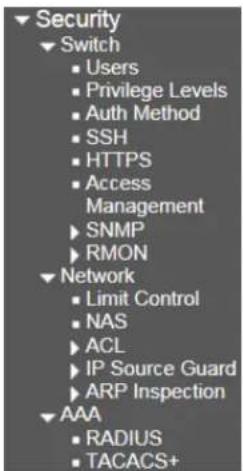
2.6.1 Switch
2.6.1.1 Users
Users Configuration

flowchart
graph LR
    A["User Name"] --> B["Privilege Level admin 15"]
    C["Add New User"] --> D["Add User"]
    D --> E["User Settings"]
    E --> F["User Name"]
    E --> G["Password"]
    E --> H["Password (again)"]
    E --> I["Privilege Level 0"]
    F --> J["Save"]
    G --> K["Reset"]
    H --> L["Cancel"]
Users Configuration 1
Users Configuration 2
Users Configuration
- Click the "Add New User" command button to add a new user.
Add User
- Enter the username, password, confirmation password and user privilege registration one by one.
- User Privilege Level: The allowed range is 0 to 15. If the level is 15, it can visit all groups for it is given the privilege to control the devise completely, but other values need to be referenced of each set of privilege levels. The user's permission must be equal to or more than the group privilege level to have access to the group.
• In the defaulted setting, most of group privilege level 5 only can read, level 10 can read and write. System maintenance (software upload, factory default and etc.) requires the user privilege level is 15.
• Generally, privilege level 15 can be used for administrator accounts, privilege level 10 for standard user accounts, and privilege level 5 for customer accounts.
2.6.1.2 Privilege Level
Privilege Level Configuration
| Group Name | Privilege Levels | |||
| Configuration Read-only | Configuration/Execute Read/write | Status/Statistics Read-only | Status/Statistics Read/write | |
| Appreciation | 5 ✓ | 11 ✓ | 5 ✓ | 10 ✓ |
| Debug | 15 ✓ | 11 ✓ | 15 ✓ | 15 ✓ |
| DHCP | 5 ✓ | 11 ✓ | 5 ✓ | 10 ✓ |
| CHDPv6_Dient | 5 ✓ | 11 ✓ | 5 ✓ | 10 ✓ |
| Diagnostics | 5 ✓ | 11 ✓ | 5 ✓ | 10 ✓ |
| BPS | 6 ✓ | 11 ✓ | 8 ✓ | 10 ✓ |
| ERPS | 5 ✓ | 11 ✓ | 5 ✓ | 10 ✓ |
| ETH_LINK_OAM | 5 ✓ | 11 ✓ | 5 ✓ | 10 ✓ |
| EVC | 5 ✓ | 11 ✓ | 5 ✓ | 10 ✓ |
| Green_Ethermet | 5 ✓ | 11 ✓ | 5 ✓ | 10 ✓ |
| IP | 5 ✓ | 11 ✓ | 5 ✓ | 10 ✓ |
| IPMC_Gnapping | 5 ✓ | 11 ✓ | 5 ✓ | 10 ✓ |
| JSON_RPC | 5 ✓ | 11 ✓ | 5 ✓ | 10 ✓ |
| JSON_RPC_Notification | 5 ✓ | 11 ✓ | 5 ✓ | 10 ✓ |
| LACF | 5 ✓ | 11 ✓ | 5 ✓ | 10 ✓ |
| LLDP | 5 ✓ | 11 ✓ | 5 ✓ | 10 ✓ |
| Loop_Project | 5 ✓ | 11 ✓ | 5 ✓ | 10 ✓ |
| MAC_Table | 5 ✓ | 11 ✓ | 5 ✓ | 10 ✓ |
| Maintenance | 15 ✓ | 11 ✓ | 15 ✓ | 15 ✓ |
| MEP | 5 ✓ | 11 ✓ | 5 ✓ | 10 ✓ |
| NTP | 5 ✓ | 11 ✓ | 5 ✓ | 10 ✓ |
| Ports | 5 ✓ | 11 ✓ | 1 ✓ | 10 ✓ |
| Private_VLANs | 5 ✓ | 11 ✓ | 3 ✓ | 10 ✓ |
| GoS | 5 ✓ | 11 ✓ | 8 ✓ | 10 ✓ |
| RMmr | 5 ✓ | 11 ✓ | 5 ✓ | 10 ✓ |
| Security | 5 ✓ | 11 ✓ | 5 ✓ | 10 ✓ |
| sPlex | 5 ✓ | 11 ✓ | 5 ✓ | 10 ✓ |
| Spanning_Tree | 5 ✓ | 11 ✓ | 5 ✓ | 10 ✓ |
| System | 5 ✓ | 11 ✓ | 1 ✓ | 10 ✓ |
| UDLD | 5 ✓ | 11 ✓ | 5 ✓ | 10 ✓ |
| UPnP | 5 ✓ | 11 ✓ | 5 ✓ | 10 ✓ |
| VCL | 5 ✓ | 11 ✓ | 5 ✓ | 10 ✓ |
| VLAN_Translation | 5 ✓ | 11 ✓ | 5 ✓ | 10 ✓ |
| VLANs | 5 ✓ | 11 ✓ | 5 ✓ | 10 ✓ |
| Voice_VLAN | 5 ✓ | 11 ✓ | 5 ✓ | 10 ✓ |
| XXRF | 5 ✓ | 11 ✓ | 5 ✓ | 10 ✓ |
Save Reset
Privilege Registration Dialog
Each group has an authorization privilege level for the subgroup:
- Configuration Read-only
- Configuration/Execute Read/write
• Status/statistics Read-only
• Status/statistics Read/write (e.g Used for Statistical data).
User privileges should be the same or greater than the authorization privilege level in order to be able to access the group.
Note that some web pages (such as MPLS-TP and MEP BFD pages) are JSON based to transfer dynamic data between the web server and the application.
These pages need to be configured read-write privilege of js on rpc group before any operation. This requirement must be met first, and then it will evaluate the current privilege level according to the given method.
- For example, it assumes that the MPLS-TP page only allows read-only attributes below privilege level 5, the privilege configuration should be configured as jsonrpc:5,5,5 and mplstp:5,10,5,10.
2.6.1.3 Auth Method
Authentication Method Configuration
| Client | Methods | |||||
| console | local | √ | no | √ | no | √ |
| telnet | local | √ | no | √ | no | √ |
| ssh | local | √ | no | √ | no | √ |
| http | local | √ | no | √ | no | √ |
Command Authorization Method Configuration
| Client | Method | Cmd Lvl | Cfg Cmd |
| console | no √ | 0 | □ |
| telnet | no √ | 0 | □ |
| ssh | no √ | 0 | □ |
Accounting Method Configuration
| Client | Method | Cmd Lvl | Exec |
| console | no √ | ||
| telnet | no √ | ||
| ssh | no √ |
| Save | Reset |
Auth Method Dialog
Authentication Method Configuration:
It allows you to log in to the switch through a management client interface to configure how users are authenticated.
It can be authenticated through the following four Clients:
- console.
- telnet.
- ssh.
- HTTP.
There are four ways of authentication methods.
• No: Authentication is disabled, it's impossible to access the switch.
- Local: Authenticated through a local user database.
• Radius: Authenticated through remote Radius server.
• Tacacs: Authenticated through remote Tacacs and server.
Command Authorization Method Configuration:
Authenticated through the command authorization method.
• no: Authentication is disabled, it's impossible to access the switch.
• Tacacs: Authenticated through remote Tacacs and server.
• If all remote servers are offline, users can access CLI commands based on their own privilege levels.
Accounting Method Configuration:
Authenticated through accounting method.
• no: Authentication is disabled, it's impossible to access the switch.
• Tacacs: Authenticated through remote Tacacs and server.
- CMD LvL allows accounting for all commands with the privilege levels that are higher than or equal to this level
- The valid value is 0 to 15.
Leave the field blank to disable command account authentication.
Log in with the account Exec.
2.6.1.4 SSH

Picture 26 : SSH Configuration Dialog
SSHMode: It defaults enabled mode to Enabled and disabled mode to Disabled.
Click "Save" to save or cancel configuration.
2.6.1.5 HTTPS
HTTPS Configuration

HTTPS Configuration Dialog
HTTPS Mode defaults disabled mode to Disabled and enabled mode to Enabled.
Certificate Maintain
There are four ways of certificate maintain.
- None: No operation.
• Delete: Delete the current certificate.
• Upload: Upload a PEM file of certificate. The possible method is via Web browser or URL.
• Generate: Generate a new self-signed RSA certificate.
2.6.1.6 Access Management
Access Management Configuration


Access Management Dialog
Access Management Mode Switch It defaults disabled mode to Disabled and enabled mode to Enabled.
- Click "Add New Entry" to add a new entry. Enter the VALI ID and the address of Start IP and End IP, and then select the corresponding access management method.
- Click "Save" to save and cancel configuration.
2.6.1.7 SNMP
2.6.1.7.1 System
SNMP System Configuration
| Mode | Enabled |
| Version | SNMP v2c |
| Read Community | public |
| Write Community | private |
| Engine ID | 800007e5017f000001 |
SNMP System Configuration Dialog
Mode
Indicates the SNMP mode operation. Possible modes are:
- Enabled: Enable SNMP mode operation.
• Disabled: Disable SNMP mode operation.
Version
Indicates the SNMP supported version. Possible versions are:
• SNMP v1: Set SNMP supported version 1.
• SNMP v2c: Set SNMP supported version 2c.
• SNMP v3: Set SNMP supported version 3.
Read Community
Indicates the community read access string to permit access to SNMP agent. The allowed string length is 0 to 255, and the allowed content is the ASCII characters from 33 to 126. The field is applicable only when SNMP version is SNMPv1 or SNMPv2c. If SNMP version is SNMPv3, the community string will be associated with SNMPv3 communities' table. It provides more flexibility to configure security name than a SNMPv1 or SNMPv2c community string. In addition to community string, a particular range of source addresses can be used to restrict source subnet.
Write Community
Indicates the community write access string to permit access to SNMP agent. The allowed string length is 0 to 255, and the allowed content is the ASCII characters from 33 to 126. The field is applicable only when SNMP version is SNMPv1 or SNMPv2c. If SNMP version is SNMPv3, the community string will be associated with SNMPv3 communities' table. It provides more flexibility to configure security name than a SNMPv1 or SNMPv2c community string. In addition to community string, a particular range of source addresses can be used to restrict source subnet.
Engine ID
Indicates the SNMPv3 engine ID. The string must contain an even number (in hexadecimal format) with number of digits between 10 and 64, but all-zeros and all-'F's are not allowed. Change of the Engine ID will clear all original local users.
Click "Save" to save or cancel configuration.
2.6.1.7.2 Trap
Trap Configuration
Global Settings

Trap Destination Configurations

Trap Configuration Dialog
It defaults disabled mode to Disabled and enabled mode to Enabled.
Click "Save" to enter the configuration as shown below.
SNMP Trap Configuration

SNMP Trap Event


SNMP Trap Configuration
- Trap Config Name: It specifies a descriptive name for this SNMPTrap entry.
-
Trap Mode: It indicates SNMPTrap mode operation. Two types are followed.
-
Enabled: Enabled SNMPTrap mode operation.
- Disabled: Disabled SNMPTrap mode operation.
- Trap Version: It indicates SNMPTrap supported version.
- SNMP v1: Set SNMPTrap supported version 1.
- SNMP v2c: Set SNMPTrap supported version 2c.
o SNMP v3: Set SNMPTrap supported version 3.
- TrapCommunity: It instructs the Community to access the string when sending an SNMPTrap packet. The allowed string length is 0 to 255, and the allowed content are ASCII characters that from 0x21 to 0x7E.
- Trap Destination Address: It instructs the destination address of SNMPTrap. It allows a valid IP address to be counted in decimal notation ('x.y.z.w'), also a valid CPU name. The valid CPU name is combined with alpha character (A-Z;a-z), number (0-9), dot (.) and dase(-). Blank is
not allowed. The first character must be an alpha character. The first character and the last character cannot be a dot or a dash.
- Trap Destination Port: It instructs the SNMPTrap destination port. The SNMP agent will send messages through this port, the port range is 1 to 65535. The defaulted SNMPTrap port is 162.
-
Trap Inform Mode: It instructs SNMPTrap inform mode operation. Shown as below.
-
Enabled: Enabled SNMPTrap Inform Mode operation.
-
Disabled: Disabled SNMPTrap Inform Mode operation.
-
Trap Inform Timeout (Seconds): It instructs SNMPTrap Inform Timeout (Seconds). The allowed range is 0-2147.
- Trap Inform Retry Times: It instructs SNMPTrap Inform Retry Times. The allowed range is 0-225.
-
Trap Probe Security Engine ID: It instructs SNMPTrap Probe Security Engine ID Mode operation. Shown as below.
-
Enabled: Enabled SNMPTrap Probe Security Engine ID mode operation.
- Disabled: Disabled SNMPTrap Probe Security Engine ID mode operation.
- Trap Security Engine ID: It instructs SNMPTrap Security Engine ID. SNMPv3 sends a Trap and notifies us to use USM for authentication and privacy. It needs an unique engine ID for these Trap and notice. This ID will be automatic detected when the Trap Probe Security Engine ID is enabled. Otherwise, the specific ID in the field will be used. The string must contain an double number (hexadecimal format), these numbers are from 10 to 64, but all 0s and all -Fs are not allowed.
- Trap Security Name: It instructs SNMPTrap security name. SNMPv3 obtains a name and notifies us to use USM for authentication and privacy. It needs a unique security name when Trap and notice are enabled.
SNMP Trap Event
• System: System Trap Event includes the following content:
Hot Enabled: The switch has been restarted from an already enabled state.
Cool Enabled: The switch is powered up or powered by a power cycle (power failure).
• Switch: In indicates the Trap of setting group.
• STP: Select the check box to enable STPTrap. Clear the STPTrap.
- Select the check box to enable RMONTrap. Clear the RMONTrap.
• Interface: It indicates the Trap of interface group.
• Connection: Non/specific/all ports are connected to the Trap.
• Connection: Non/specific/all ports are connected to the offline.
• LLDP: Non/specific/all ports are LLDP Trap.
- Click the Save button after finishing all the Trap settings.
SNMPv3 Community Configuration
| Delete | Community | Source IP | Source Mask |
| public | 0.0.0.0 | 0.0.0.0 | |
| private | 0.0.0.0 | 0.0.0.0 |


Community Configuration
Delete: Check for deleted entries. They'll be deleted during the next save.
Community: It indicates that the Community accesses to string that allows to access to the SNMPv3 proxy.
The allowed string length is 1-32, and the allowed content are ASCII characters that from 0x21 to 0x7E. The Community string will be treated as a security name and mapped to a SNMPv1 or SNMPv2c Community string.
This string is distinguished from capital and little letter.
2.6.1.7.4 Users
Source IP: It indicates SNMP Source IP. When it's combined with a source mask, you can use a specific range of source IP to limit the source subnet.
Source Mask: It indicates SNMP Source Mask.
SNMPv3 User Configuration
| Delete | Engine ID | User Name | Security Level | Authentication Protocol | Authentication Password | Privacy Protocol | Privacy Password |
| □ | 600007e5017f000001 | default_user | NoAuth. NoPriv | None | None | None | None |
SNMP User Configuration 1
Click "Add New Entry" will display the following configuration page.
SNMPv3 User Configuration
| Delete | Engine ID | User Name | Security Level | Authentication Protocol | Authentication Password | Privacy Protocol | Privacy Password |
| 800007e5017f000001 | default_user | NoAuth, NoPriv | None | None | None | None | |
| Delete | Auth, Priv | MD5 | DES |
SNMP User Configuration 2
SNMPv3 User Configuration
Delete
Check to delete the entry. It will be deleted during the next save.
Engine ID
An octet string identifying the engine ID that this entry should belong to. The string must contain an even number (in hexadecimal format) with number of digits between 10 and 64, but all-zeros and all-'F's are not allowed. The SNMPv3 architecture uses the User-based Security Model (USM) for message security and the View-based Access Control Model (VACM) for access control. For the USM entry, the usmUserEngineID and usmUserName are the entry's keys. In a simple agent, usmUserEngineID is always that agent's own snmpEngineID value. The value can also take the value of the snmpEngineID of a remote SNMP engine with which this user can communicate. In other words, if user engine ID equal system engine ID then it is local user; otherwise it's remote user.
User Name
A string identifying the user name that this entry should belong to. The allowed string length is 1 to 32, and the allowed content is ASCII characters from 33 to 126.
Security Level
Indicates the security model that this entry should belong to. Possible security models are:
• NoAuth, NoPriv: No authentication and no privacy.
• Auth, NoPriv: Authentication and no privacy.
• Auth, Priv: Authentication and privacy.
The value of security level cannot be modified if entry already exists. That means it must first be ensured that the value is set correctly.
Authentication Protocol
Indicates the authentication protocol that this entry should belong to. Possible authentication protocols are:
None: No authentication protocol.
MD5: An optional flag to indicate that this user uses MD5 authentication protocol.
SHA: An optional flag to indicate that this user uses SHA authentication protocol.
The value of security level cannot be modified if entry already exists. That means must first ensure that the value is set correctly.
Authentication Password
A string identifying the authentication password phrase. For MD5 authentication protocol, the allowed string length is 8 to 32. For SHA authentication protocol, the allowed string length is 8 to 40. The allowed content is ASCII characters from 33 to 126.
Privacy Protocol
Indicates the privacy protocol that this entry should belong to. Possible privacy protocols are:
None: No privacy protocol.
DES: An optional flag to indicate that this user uses DES authentication protocol.
AES: An optional flag to indicate that this user uses AES authentication protocol.
Privacy Password
A string identifying the privacy password phrase. The allowed string length is 8 to 32, and the allowed content is ASCII characters from 33 to 126.
Click the Add New Entry button to insert a new entry into the list.
Click the "Delete" button to delete the newly inserted entry, or select the check box to delete the saved entry on the next save.
Click the "Save" button to save or change the settings.
Click the "Reset" button to restore the changes to the defaulted settings.
SNMPv3 Group Configuration
| Delete | Security Model | Security Name | Group Name |
| v1 | public | default_ro_group | |
| v1 | private | default_rw_group | |
| v2c | public | default_ro_group | |
| v2c | private | default_rw_group | |
| usm | default_user | default_rw_group |
Add New Entry
Save
Reset
SNMPv3 Configuration
Delete
Check to delete the entry. It will be deleted during the next save.
Security Model
Indicates the security model that this entry should belong to. Possible security models are:
• v1: Reserved for SNMPv1.
• v2c: Reserved for SNMPv2c.
• usm: User-based Security Model (USM).
Security Name
A string identifying the security name that this entry should belong to. The allowed string length is 1 to 32, and the allowed content is ASCII characters from 33 to 126.
Group Name
A string identifying the group name that this entry should belong to. The allowed string length is 1 to 32, and the allowed content is ASCII characters from 33 to 126.
2.6.1.7.6 Views
SNMPv3 View Configuration
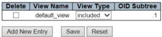
SNMPv3 View Configuration
Delete
Check to delete the entry. It will be deleted during the next save.
View Name
A string identifying the view name that this entry should belong to. The allowed string length is 1 to 32, and the allowed content is ASCII characters from 33 to 126.
View Type
Indicates the view type that this entry should belong to. Possible view types are:
• included: An optional flag to indicate that this view subtree should be included.
• excluded: An optional flag to indicate that this view subtree should be excluded.
In general, if a view entry's view type is 'excluded', there should be another view entry existing with view type as 'included' and it's OID subtree should overstep the 'excluded' view entry.
OID Subtree
The OID defining the root of the subtree to add to the named view. The allowed OID length is 1 to 128. The allowed string content is digital number or asterisk (*).
2.6.1.7.7 Access
SNMPv3 Access Configuration

SNMPv3 Access Configuration
Delete
Check to delete the entry. It will be deleted during the next save.
Group Name
A string identifying the group name that this entry should belong to. The allowed string length is 1 to 32, and the allowed content is ASCII characters from 33 to 126.
Security Model
Indicates the security model that this entry should belong to. Possible security models are:
• any: Any security model accepted(v1|v2c|usm).
• v1: Reserved for SNMPv1.
• v2c: Reserved for SNMPv2c.
• usm: User-based Security Model (USM).
Security Level
Indicates the security model that this entry should belong to. Possible security models are:
• NoAuth, NoPriv: No authentication and no privacy.
• Auth, NoPriv: Authentication and no privacy.
• Auth, Priv: Authentication and privacy.
2.6.1.8 RMON
2.6.1.8.1 Statistics
Read View Name
The name of the MIB view defining the MIB objects for which this request may request the current values. The allowed string length is 1 to 32, and the allowed content is ASCII characters from 33 to 126.
Write View Name
The name of the MIB view defining the MIB objects for which this request may potentially set new values. The allowed string length is 1 to 32, and the allowed content is ASCII characters from 33 to 126.
RMON Statistics Configuration
| Delete | ID | Data Source | |
| Delete | .1.3.6.1.2.1.2.2.1.1. | 0 | |
RMON Statistics Configuration
• Delete: Check for the deleted entry. It will be deleted during the next save.
• ID: It indicates the index of the entry. The range is from 1 to 65535.
• Data Source: It indicates the monitored port ID.
2.6.1.8.2 History
RMON History Configuration
| Delete | ID | Data Source | Interval | Buckets | Buckets Granted | ||
| Delete | .1.3.6.1.2.1.2.2.1.1. | 0 | 1800 | 50 | |||
• ID: It indicates the index of the entry. The range is from 1 to 65535.
• Data Source: It indicates Themo monitor port ID.
• Interval: It indicates the polling interval. By default, 1800s are specified. The allowed range is 1 to 3600 s.
- Buckets: It indicates that the number of Buckets is required for this entry. By default, 50 is specified. The allowed range is 1 to 3600.
• Given Buckets Number: It indicates the given Buckets number.
Click the Add New Entry button to insert a new entry into the list.
Click the "Delete" button to delete the newly inserted entry, or select the check box to delete the saved entry on the next save.
Click the "Save" button to save or change the settings.
Click the "Reset" button to restore the changes to the defaulted settings.
2.6.1.8.3 Alarm
The RMON alarm configuration defines the specific criteria for generating response events. It can be set to test data at any given time interval and can monitor absolute values or changed values.
Alerts can also be set to respond to rising or falling thresholds
RMON Alarm Configuration
| Delete | ID | Interval | Variable | Sample type | Value | Startup Alarm | Rising Threshold | Rising Index | Falling Threshold | Falling Index | ||
| Delete | 30 | 1:36.1:2 1:2 2:1 | 0.0 | Date | 0 | RisingOfailing | 0 | 0 | 0 | 0 | ||
| Add New Entry | Save | Reset | ||||||||||
RMON Alarm Configuration
• ID: It indicates the index of the entry. The range is from 1 to 65535.
• Interval: The polling interval is used for sampling and comparing the rising and falling thresholds. The range is from 1 to 231s.
• Variable: The sampled object number of MIB Variable. Only the type of variable ifEntry.n.m may be sampled.
• Possible Variable: Vaccination, protein kinase, nuclear protein kinase, zymogen, nucleoprotein, water molecule, outer nuclear protein, outer nuclear protein, outer nuclear protein, outer loop, outer loop and outer loop.
• Sample Type: A test of absolute or relative changes to a specified variable.
• Absolute: This variable is compared to the threshold that in the end of the sampling period.
• Delta: The last sample is subtracted from the current value and the balance is compared to the threshold.
• Value: It's the statistical value during the last sampling period.
- Startup Alarm: Select the method that is used to sample the selected variable, calculate the value that is compared against the threshold.
- Rise or Fall: It triggers an alarm when the first value is greater than the rising threshold or less than the falling threshold.
- Rise: It triggers an alarm when the first value is greater than the rising threshold.
- Fall: It triggers an alarm when the first value is less than the falling threshold.
• Threshold Rise: If the current value is greater than the rising threshold and the last sample value is less than this threshold, an alarm is triggered
When a rising event occurs, another such event will not be generated until the sampled value falls below the threshold, reaches the falling threshold, and then returns to the rising threshold again.
The threshold range is -2147483647 to 2147483647.
• Rising Index: It refers to the rising index of an event. The range is from 1 to 65535.
- Falling Threshold:
If the current value is less than the falling threshold, the last sampled value is greater than this threshold, an alarm is triggered.
After generating a falling event, another such event will not be generated until the sampled value rises to the threshold, and it reaches the value of the threshold and then returns to the failed threshold again.
○ (The range is -2147483647 to 2147483647.)
• Falling Index: It refers to the falling index of an event. The range is from 1 to 65535.
- Click the "Add New Entry" button to insert a new entry into the list.
- Click the "Delete" button to delete the newly inserted entry or select the checkbox to delete the saved entry on the next save.
- Click the "Save" button to save or change the settings.
- Click the "Reset" button to restore the changes to the defaulted settings.
2.6.1.8.4 Event
RMON Event Configuration
| Delete | ID | Desc | Type | Community | Event Last Time |
| Delete | none | public | 0 |
Picture 40: RMON Event Configuration
- Delete: Check for the deleted entry, it will be deleted during the next save.
• ID: It indicates the index of an ID. The range is from 1 to 65535.
• Desc: Enter a descriptive comment for this entry.
• Type: Select an event type that will occur when an alarm is triggered.
• None: Do not generate an event.
• Log: It will generate a RMON log entry when the event is triggered.
- snmptrap: Send Trap messages to Trap servers of all configurations.
- logandtrap: Record an event and send a Trap message.
• Community: A password-like Community string is sent with this Trap. Although the Community string can be set on this configuration page, it is recommended to define it on the SNMPTrap configuration page before configuring it. The allowed character is 0-127.
• Event Last Time: It is the sysUpTime value when the event was last generated for this entry.
Port Security Limit Control Configuration Dialog
2.6.2 Network Security
2.6.2.1 Limit Control
Port Security Limit Control Configuration
System Configuration
| Mode | Disabled | |
| Aging Enabled | ||
| Aging Period | 3600 | seconds |
Port Configuration
| Port | Mode | Limit | Action | State | Re-open | |
| * | <> | 4 | <> | ✓ | ||
| 1 | Disabled | 4 | None | ✓ | Disabled | Reopen |
| 2 | Disabled | 4 | None | ✓ | Disabled | Reopen |
| 3 | Disabled | 4 | None | ✓ | Disabled | Reopen |
| 4 | Disabled | 4 | None | ✓ | Disabled | Reopen |
| 5 | Disabled | 4 | None | ✓ | Disabled | Reopen |
| 6 | Disabled | 4 | None | ✓ | Disabled | Reopen |
| 7 | Disabled | 4 | None | ✓ | Disabled | Reopen |
| 8 | Disabled | 4 | None | ✓ | Disabled | Reopen |
| 9 | Disabled | 4 | None | ✓ | Disabled | Reopen |
| 10 | Disabled | 4 | None | ✓ | Disabled | Reopen |
| 11 | Disabled | 4 | None | ✓ | Disabled | Reopen |
| 12 | Disabled | 4 | None | ✓ | Disabled | Reopen |
Save Reset
System Configuration
A. Mode: Enable or disable the Global Port Security Limit Control.
a. If globally disabled, other modules may still use the underlying function, but the limit check and corresponding actions are disabled.
B. Aging Enabled: If enabled, the safe MAC address will get ager as it ages.
a. As the growing of age, the timer will be enabled as soon as the end host is protected. When the timer is expired, the switch begins looking for Frames from the end host. If such a Frame is not visible in the next aging cycle, the end host is considered to be disconnected and the corresponding resource is released on the switch.
C. Aging Period: If Aging Enabled is checked, then the aging period is controlled with this input. If other modules are using the underlying port security for securing MAC addresses, they may have other requirements to the aging period. The underlying port security will use the shorter requested aging period of all modules that use the functionality.
a. The Aging Period can be set to a number between 10 and 10,000,000 seconds.
b. To understand why aging may be desired, consider the following scenario: Suppose an end-host is connected to a 3rd party switch or hub, which in turn is connected to a port on this switch on which Limit Control is enabled. The end-host will be allowed to forward if the limit is not exceeded. Now suppose that the end-host logs off or powers down. If it wasn't for aging, the end-host would still take up resources on this switch and will be allowed to forward. To overcome this situation, enable aging. With aging enabled, a timer is started once the end-host gets secured. When the timer expires, the switch starts looking for frames from the end-host, and if such frames are not seen within the next Aging Period, the end-host is assumed to be disconnected, and the corresponding resources are freed on the switch.
Port Configuration
A. Port: It indicates the port number.
B. Mode: Enable or disable Port Security Limit Control on each port. In order to let it work, the Port Security Limit Control needs to be enabled globally and on the port.
C. Limit: It indicates that the max number of MAC addresses that can be protected on this port. This number cannot exceed 1024.
a. If the limitation is exceeded, take the appropriate action.
D. Action: If Limit is reached, the switch can take one of the following actions:

E. None: Do not allow more than Limit MAC addresses on the port, but take no further action.
F. Trap: If Limit + 1 MAC addresses is seen on the port, send an SNMP trap. If Aging is disabled, only one SNMP trap will be sent, but with Aging enabled, new SNMP traps will be sent every time the limit gets exceeded.
G. shutdown: If Limit + 1 MAC addresses is seen on the port, shut down the port. This implies that all secured MAC addresses will be removed from the port, and no new address will be learned. Even if the link is physically disconnected and reconnected on the port (by disconnecting the cable), the port will remain shut down. There are three ways to re-open the port:
- Boot the switch,
- Disable and re-enable Limit Control on the port or the switch,
- Click the Reopen button.
H. Trap & Shutdown: If Limit + 1 MAC addresses is seen on the port, both the "Trap" and the "Shutdown" actions described above will be taken.
I. State: This column shows the current state of the port as seen from the Limit Control's point of view. The state takes one of four values:
- Disabled: Limit Control is either globally disabled or disabled on the port
- Ready: The limit is not yet reached. This can be shown for all actions
- Limit Reached: Indicates that the limit is reached on this port. This state can only be shown if Action is set to None or Trap.
- Shutdown: Indicates that the port is shut down by the Limit Control module. This state can only be shown if Action is set to Shutdown or Trap & Shutdown
Network Access Server Configuration
System Configuration

Port Configuration


NAS configuration
System Configuration
Mode
Indicates if NAS is globally enabled or disabled on the switch. If globally disabled, all ports are allowed forwarding of frames.
Reauthentication Enabled
If checked, successfully authenticated supplicants/clients are reauthenticated after the interval specified by the Reauthentication Period. Reauthentication for 802.1X-enabled ports can be used to detect if a new device is plugged into a switch port or if a supplicant is no longer attached. For MAC-based ports, reauthentication is only useful if the RADIUS server configuration has changed. It does not involve communication between the switch and the client, and therefore doesn't imply that a client is still present on a port (see Aging Period below).
Reauthentication Period
Determines the period, in seconds, after which a connected client must be reauthenticated. This is only active if the Reauthentication Enabled checkbox is checked. Valid values are in the range 1 to 3600 seconds.
EAPOL Timeout
Determines the time for retransmission of Request Identity EAPOL frames. Valid values are in the range 1 to 65535 seconds. This has no effect for MAC-based ports.
Aging Period
This setting applies to the following modes, i.e. modes using the Port Security functionality to secure MAC addresses:
- Single 802.1X
- Multi 802.1X
- MAC-Based Auth.
When the NAS module uses the Port Security module to secure MAC addresses, the Port Security module needs to check for activity on the MAC address in question at regular intervals and free resources if no activity is seen within a given period of time. This parameter controls exactly this period and can be set to a number between 10 and 1000000 seconds.
If reauthentication is enabled and the port is in an 802.1X-based mode, this is not so critical, since supplicants that are no longer attached to the port will get removed upon the next reauthentication, which will fail. But if reauthentication is not enabled, the only way to free resources is by aging the entries.
For ports in MAC-based Auth. mode, reauthentication doesn't cause direct communication between the switch and the client, so this will not detect whether the client is still attached or not, and the only way to free any resources is to age the entry.
Hold Time
This setting applies to the following modes, i.e. modes using the Port Security functionality to secure MAC addresses:
- Single 802.1X
- Multi 802.1X
- MAC-Based Auth.
If a client is denied access - either because the RADIUS server denies the client access or because the RADIUS server request times out (according to the timeout specified on the
"Configuration→Security→AAA" page) - the client is put on hold in the Unauthorized state. The hold timer does not count during an on-going authentication.
In MAC-based Auth. mode, the switch will ignore new frames coming from the client during the hold time.
The Hold Time can be set to a number between 10 and 1000000 seconds.
RADIUS-Assigned QoS Enabled
RADIUS-assigned QoS provides a means to centrally control the traffic class to which traffic coming from a successfully authenticated supplicant is assigned on the switch. The RADIUS server must be configured to transmit special RADIUS attributes to take advantage of this feature (see RADIUS-Assigned QoS Enabled below for a detailed description).
The "RADIUS-Assigned QoS Enabled" checkbox provides a quick way to globally enable/disable RADIUS-server assigned QoS Class functionality. When checked, the individual ports' ditto setting determines whether RADIUS-assigned QoS Class is enabled on that port. When unchecked, RADIUS-server assigned QoS Class is disabled on all ports.
RADIUS-Assigned VLAN Enabled
RADIUS-assigned VLAN provides a means to centrally control the VLAN on which a successfully authenticated supplicant is placed on the switch. Incoming traffic will be classified to and switched on the RADIUS-assigned VLAN. The RADIUS server must be configured to transmit special RADIUS attributes to take advantage of this feature (see RADIUS-Assigned VLAN Enabled below for a detailed description).
The "RADIUS-Assigned VLAN Enabled" checkbox provides a quick way to globally enable/disable RADIUS-server assigned VLAN functionality. When checked, the individual ports' ditto setting determines whether RADIUS-assigned VLAN is enabled on that port. When unchecked, RADIUS-server assigned VLAN is disabled on all ports.
Guest VLAN Enabled
A Guest VLAN is a special VLAN - typically with limited network access - on which 802.1X-unaware clients are placed after a network administrator-defined timeout. The switch follows a set of rules for entering and leaving the Guest VLAN as listed below.
The "Guest VLAN Enabled" checkbox provides a quick way to globally enable/disable Guest VLAN functionality. When checked, the individual ports' ditto setting determines whether the port can be moved into Guest VLAN. When unchecked, the ability to move to the Guest VLAN is disabled on all ports.
Guest VLAN ID
This is the value that a port's Port VLAN ID is set to if a port is moved into the Guest VLAN. It is only changeable if the Guest VLAN option is globally enabled.
Valid values are in the range [1; 4095].
Max. Reauth. Count
The number of times the switch transmits an EAPOL Request Identity frame without response before considering entering the Guest VLAN is adjusted with this setting. The value can only be changed if the Guest VLAN option is globally enabled.
Valid values are in the range [1; 255].
Allow Guest VLAN if EAPOL Seen
The switch remembers if an EAPOL frame has been received on the port for the life-time of the port. Once the switch considers whether to enter the Guest VLAN, it will first check if this option is enabled or disabled. If disabled (unchecked; default), the switch will only enter the Guest VLAN if an EAPOL frame has not been received on the port for the life-time of the port. If enabled (checked), the switch will consider entering the Guest VLAN even if an EAPOL frame has been received on the port for the life-time of the port.
The value can only be changed if the Guest VLAN option is globally enabled.
Port Configuration
Port
The port number for which the configuration below applies.
Admin State
If NAS is globally enabled, this selection controls the port's authentication mode. The following modes are available:
- Force Authorized
In this mode, the switch will send one EAPOL Success frame when the port link comes up, and any client on the port will be allowed network access without authentication.
• Force Unauthorized
In this mode, the switch will send one EAPOL Failure frame when the port link comes up, and any client on the port will be disallowed network access.
- Port-based 802.1X
In the 802.1X-world, the user is called the supplicant, the switch is the authenticator, and the RADIUS server is the authentication server. The authenticator acts as the man-in-the-middle, forwarding requests and responses between the supplicant and the authentication server. Frames sent between the supplicant and the switch are special 802.1X frames, known as EAPOL (EAP Over LANs) frames. EAPOL frames encapsulate EAP PDUs (RFC3748). Frames sent between the switch and the RADIUS server are RADIUS packets. RADIUS packets also encapsulate EAP PDUs together with other attributes like the switch's IP address, name, and the supplicant's port number on the switch. EAP is very flexible, in that it allows for different authentication methods, like MD5-Challenge, PEAP, and TLS. The important thing is that the authenticator (the switch) doesn't need to know which authentication method the supplicant and the authentication server are using, or how many information exchange frames are needed for a particular method. The switch simply encapsulates the EAP part of the frame into the relevant type (EAPOL or RADIUS) and forwards it.
When authentication is complete, the RADIUS server sends a special packet containing a success or failure indication. Besides forwarding this decision to the supplicant, the switch uses it to open up or block traffic on the switch port connected to the supplicant.
Note: Suppose two backend servers are enabled and that the server timeout is configured to X seconds (using the AAA configuration page), and suppose that the first server in the list is currently down (but not considered dead). Now, if the supplicant retransmits EAPOL Start frames at a rate faster than X seconds, then it will never get authenticated because the switch will cancel on-going backend authentication server requests whenever it receives a new EAPOL Start frame from the supplicant. And since the server hasn't yet failed (because the X seconds haven't expired), the same server will be contacted upon the next backend authentication server request from the switch. This scenario will loop forever. Therefore, the server timeout should be smaller than the supplicant's EAPOL Start frame retransmission rate.
- Single 802.1X
In port-based 802.1X authentication, once a supplicant is successfully authenticated on a port, the whole port is opened for network traffic. This allows other clients connected to the port (for instance through a hub) to piggy-back on the successfully authenticated client and get network access even though they really aren't authenticated. To overcome this security breach, use the Single 802.1X variant.
Single 802.1X is really not an IEEE standard, but features many of the same characteristics as does port-based 802.1X. In Single 802.1X, at most one supplicant can get authenticated on the port at a time. Normal EAPOL frames are used in the communication between the supplicant and the switch. If more than one supplicant is connected to a port, the one that comes first when the port's link comes up will be the first one considered. If that supplicant doesn't provide valid credentials within a certain amount of time, another supplicant will get a chance. Once a supplicant is successfully authenticated, only that supplicant will be allowed access. This is the most secure of all the supported modes. In this mode, the Port Security module is used to secure a supplicant's MAC address once successfully authenticated.
- Multi 802.1X
- Multi 802.1X is - like Single 802.1X - not an IEEE standard, but a variant that features many of the characteristics. In Multi 802.1X, one or more supplicants can get authenticated on the same port at the same time. Each supplicant is authenticated individually and secured in the MAC table using the Port Security module.
In Multi 802.1X it is not possible to use the multicast BPDU MAC address as destination MAC address for EAPOL frames sent from the switch towards the supplicant, since that
would cause all supplicants attached to the port to reply to requests sent from the switch. Instead, the switch uses the supplicant's MAC address, which is obtained from the first EAPOL Start or EAPOL Response Identity frame sent by the supplicant. An exception to this is when no supplicants are attached. In this case, the switch sends EAPOL Request Identity frames using the BPDU multicast MAC address as destination - to wake up any supplicants that might be on the port.
The maximum number of supplicants that can be attached to a port can be limited using the Port Security Limit Control functionality.
- MAC-based Auth.
Unlike port-based 802.1X, MAC-based authentication is not a standard, but merely a best-practices method adopted by the industry. In MAC-based authentication, users are called clients, and the switch acts as the supplicant on behalf of clients. The initial frame (any kind of frame) sent by a client is snooped by the switch, which in turn uses the client's MAC address as both username and password in the subsequent EAP exchange with the RADIUS server. The 6-byte MAC address is converted to a string on the following form "xx-xx-xx-xx-xx-xx", that is, a dash (-) is used as separator between the lower-cased hexadecimal digits. The switch only supports the MD5-Challenge authentication method, so the RADIUS server must be configured accordingly.
When authentication is complete, the RADIUS server sends a success or failure indication, which in turn causes the switch to open up or block traffic for that particular client, using the Port Security module. Only then will frames from the client be forwarded on the switch. There are no EAPOL frames involved in this authentication, and therefore, MAC-based Authentication has nothing to do with the 802.1X standard.
The advantage of MAC-based authentication over 802.1X-based authentication is that the clients don't need special supplicant software to authenticate. The disadvantage is that MAC addresses can be spoofed by malicious users - equipment whose MAC address is a valid RADIUS user can be used by anyone. Also, only the MD5-Challenge method is supported. The maximum number of clients that can be attached to a port can be limited using the Port Security Limit Control functionality.
RADIUS-Assigned QoS Enabled
When RADIUS-Assigned QoS is both globally enabled and enabled (checked) on a given port, the switch reacts to QoS Class information carried in the RADIUS Access-Accept packet transmitted by the RADIUS server when a supplicant is successfully authenticated. If present and valid, traffic received on the supplicant's port will be classified to the given QoS Class. If (re-)authentication fails or the RADIUS Access-Accept packet no longer carries a QoS Class or it's invalid, or the supplicant is otherwise no longer present on the port, the port's QoS Class is immediately reverted to the original QoS Class (which may be changed by the administrator in the meanwhile without affecting the RADIUS-assigned).
This option is only available for single-client modes, i.e.
- Port-based 802.1X
- Single 802.1X
RADIUS attributes used in identifying a QoS Class:
The User-Priority-Table attribute defined in RFC4675 forms the basis for identifying the QoS Class in an Access-Accept packet.
Only the first occurrence of the attribute in the packet will be considered, and to be valid, it must follow this rule:
- All 8 octets in the attribute's value must be identical and consist of ASCII characters in the range '0' - '7', which translates into the desired QoS Class in the range [0; 7].
RADIUS-Assigned VLAN Enabled
When RADIUS-Assigned VLAN is both globally enabled and enabled (checked) for a given port, the switch reacts to VLAN ID information carried in the RADIUS Access-Accept packet transmitted by the RADIUS server when a supplicant is successfully authenticated. If present and valid, the port's Port VLAN ID will be changed to this VLAN ID, the port will be set to be a member of that VLAN ID, and the port will be forced into VLAN unaware mode. Once assigned, all traffic arriving on the port will be classified and switched on the RADIUS-assigned VLAN ID.
If (re-)authentication fails or the RADIUS Access-Accept packet no longer carries a VLAN ID or it's invalid, or the supplicant is otherwise no longer present on the port, the port's VLAN ID is immediately reverted to the original VLAN ID (which may be changed by the administrator in the meanwhile without affecting the RADIUS-assigned).
This option is only available for single-client modes, i.e.
- Port-based 802.1X
- Single 802.1X
For trouble-shooting VLAN assignments, use the "Monitor→VLANs→VLAN Membership and VLAN Port" pages. These pages show which modules have (temporarily) overridden the current Port VLAN configuration.
RADIUS attributes used in identifying a VLAN ID:
RFC2868 and RFC3580 form the basis for the attributes used in identifying a VLAN ID in an Access-Accept packet. The following criteria are used:
• The Tunnel-Medium-Type, Tunnel-Type, and Tunnel-Private-Group-ID attributes must all be present at least once in the Access-Accept packet.
• The switch looks for the first set of these attributes that have the same Tag value and fulfil the following requirements (if Tag == 0 is used, the Tunnel-Private-Group-ID does not need to include a Tag):
o Value of Tunnel-Medium-Type must be set to "IEEE-802" (ordinal 6).
- Value of Tunnel-Type must be set to "VLAN" (ordinal 13).
Value of Tunnel-Private-Group-ID must be a string of ASCII chars in the range '0' - '9', which is interpreted as a decimal string representing the VLAN ID. Leading '0's are discarded. The final value must be in the range [1; 4095].
Guest VLAN Enabled
When Guest VLAN is both globally enabled and enabled (checked) for a given port, the switch considers moving the port into the Guest VLAN according to the rules outlined below.
This option is only available for EAPOL-based modes, i.e.:
• Port-based 802.1X
- Single 802.1X
- Multi 802.1X
For trouble-shooting VLAN assignments, use the "Monitor→VLANs→VLAN Membership and VLAN Port" pages. These pages show which modules have (temporarily) overridden the current Port VLAN configuration.
Guest VLAN Operation:
When a Guest VLAN enabled port's link comes up, the switch starts transmitting EAPOL Request Identity frames. If the number of transmissions of such frames exceeds Max. Reauth. Count and no EAPOL frames have been received in the meanwhile, the switch considers entering the Guest VLAN. The interval between transmission of EAPOL Request Identity frames is configured with EAPOL Timeout. If Allow Guest VLAN if EAPOL Seen is enabled, the port will now be placed in the Guest VLAN. If disabled, the switch will first check its history to see if an EAPOL frame has previously been received on the port (this history is cleared if the port link goes down or the port's Admin State is changed), and if not, the port will be placed in the Guest VLAN. Otherwise, it will not move to the Guest VLAN, but continue transmitting EAPOL Request Identity frames at the rate given by EAPOL Timeout.
Once in the Guest VLAN, the port is considered authenticated, and all attached clients on the port are allowed access on this VLAN. The switch will not transmit an EAPOL Success frame when entering the Guest VLAN.
While in the Guest VLAN, the switch monitors the link for EAPOL frames, and if one such frame is received, the switch immediately takes the port out of the Guest VLAN and starts authenticating the supplicant according to the port mode. If an EAPOL frame is received, the port will never be able to go back into the Guest VLAN if the "Allow Guest VLAN if EAPOL Seen" is disabled.
Port State
The current state of the port. It can undertake one of the following values:
• Globally Disabled: NAS is globally disabled.
• Link Down: NAS is globally enabled, but there is no link on the port.
• Authorized: The port is in Force Authorized or a single-supplicant mode and the supplicant is authorized.
• Unauthorized: The port is in Force Unauthorized or a single-supplicant mode and the supplicant is not successfully authorized by the RADIUS server.
• X Auth/Y Unauth: The port is in a multi-supplicant mode. Currently X clients are authorized and Y are unauthorized.
Restart
Two buttons are available for each row. The buttons are only enabled when authentication is globally enabled and the port's Admin State is in an EAPOL-based or MAC-based mode.
Clicking these buttons will not cause settings changed on the page to take effect.
- Reauthenticate: Schedules a reauthentication whenever the quiet-period of the port runs out (EAPOL-based authentication). For MAC-based authentication, reauthentication will be attempted immediately.
The button only has effect for successfully authenticated clients on the port and will not cause the clients to get temporarily unauthorized.
• Reinitialize: Forces a reinitialization of the clients on the port and thereby a reauthentication immediately. The clients will transfer to the unauthorized state while the reauthentication is in progress.
2.6.2.3 ACL
An ACL is a sequential list that allows or denies users access to information or performs tasks on the network.
In this conversion, user can establish rules that applied to the port number to allow or deny the operation or limit the rate.
2.6.2.3.1 Ports
ACL Ports Configuration
| Port | Policy ID | Action | Rate Limiter ID | EVC Policer | EVC Policer ID | Port Redject | Mirror | Logging | Shutdown | State | Counter | |
| 1 | 0 | ✓ | ✓ | ✓ | ✓ | 1 | Disabled Part 1 Part 2 ✓ | ✓ | ✓ | ✓ | ✓ | |
| 1 | 0 | Permit ✓ | Disabled ✓ | Disabled ✓ | 1 | Disabled Part 1 Part 2 ✓ | Disabled ✓ | Disabled ✓ | Enabled ✓ | 0 | ||
| 2 | 0 | Permit ✓ | Disabled ✓ | Disabled ✓ | 1 | Disabled Part 1 Part 3 ✓ | Disabled ✓ | Disabled ✓ | Enabled ✓ | 0 | ||
| 3 | 0 | Permit ✓ | Disabled ✓ | Disabled ✓ | 1 | Disabled Part 1 Part 2 ✓ | Disabled ✓ | Disabled ✓ | Enabled ✓ | 1495 | ||
| 4 | 0 | Permit ✓ | Disabled ✓ | Disabled ✓ | 1 | Disabled Part 1 Part 2 ✓ | Disabled ✓ | Disabled ✓ | Enabled ✓ | 0 | ||
| 5 | 0 | Permit ✓ | Disabled ✓ | Disabled ✓ | 1 | Disabled Part 1 Part 2 ✓ | Disabled ✓ | Disabled ✓ | Enabled ✓ | 0 | ||
| 6 | 0 | Permit ✓ | Disabled ✓ | Disabled ✓ | 1 | Disabled Part 1 Part 2 ✓ | Disabled ✓ | Disabled ✓ | Enabled ✓ | 0 | ||
| 7 | 0 | Permit ✓ | Disabled ✓ | Disabled ✓ | 1 | Disabled Part 1 Part 2 ✓ | Disabled ✓ | Disabled ✓ | Enabled ✓ | 0 | ||
| 8 | 0 | Permit ✓ | Disabled ✓ | Disabled ✓ | 1 | Disabled Part 1 Part 2 ✓ | Disabled ✓ | Disabled ✓ | Enabled ✓ | 0 | ||
| 9 | 0 | Permit ✓ | Disabled ✓ | Disabled ✓ | 1 | Disabled Part 1 Part 2 ✓ | Disabled ✓ | Disabled ✓ | Enabled ✓ | 668274 | ||
| 10 | 0 | Permit ✓ | Disabled ✓ | Disabled ✓ | 1 | Disabled Part 1 Part 2 ✓ | Disabled ✓ | Disabled ✓ | Enabled ✓ | 0 | ||
| 11 | 0 | Permit ✓ | Disabled ✓ | Disabled ✓ | 1 | Disabled Part 1 Part 2 ✓ | Disabled ✓ | Disabled ✓ | Enabled ✓ | 0 | ||
| 12 | 0 | Permit ✓ | Disabled ✓ | Disabled ✓ | 1 | Disabled Part 1 Part 2 ✓ | Disabled✓. Disabled✓. Disabled✓. Disabled✓. Disabled✓. Disabled✓. Disabled✓. Disabled✓. Disabled✓. Disabled✓. Disabled✓. Disabled✓. Disabled✓. Disabled✓. Disabled✓. Disabled✓. Disabled✓. Disabled✓. Disabled✓. Disabled✓. Disabled✓. Disabled✓. Disabled✓. Disabled✓. Disabled✓. Disabled✓. Disabled✓. Disabled✓. Disabled✓. Disabled✓. Disabled✓. Disabled✓. Disabled✓. Disabled✓. Disabled | |||||
Port:Setting port number. “*” configuration is suitable for all ports.
Policy ID
Select the policy to apply to this port. The allowed values are 0 through 255. The default value is 0.
Action
Select whether forwarding is permitted ("Permit") or denied ("Deny"). The default value is "Permit".
Rate Limiter ID
Select which rate limiter to apply on this port. The allowed values are Disabled or the values 1 through 16. The default value is "Disabled".
EVC Policer
Select whether EVC policer is enabled or disabled. The default value is "Disabled". Note that ACL rate limiter and EVC policer cannot both be enabled.
EVC Policer ID
Select which EVC policer ID to apply on this port. The allowed values are Disabled or the values 1 through 256.
Port Redirect
Select which port frames are redirected on. The allowed values are Disabled or a specific port number and it can't be set when action is permitted. The default value is "Disabled".
Mirror
Specify the mirror operation of this port. The allowed values are:
• Enabled: Frames received on the port are mirrored.
• Disabled: Frames received on the port are not mirrored.
The default value is "Disabled".
Logging
Specify the logging operation of this port. Notice that the logging message doesn't include the 4 bytes CRC. The allowed values are:
• Enabled: Frames received on the port are stored in the System Log.
• Disabled: Frames received on the port are not logged.
The default value is "Disabled". Note: The logging feature only works when the packet length is less than 1518(without VLAN tags) and the System Log memory size and logging rate is limited.
Shutdown
Specify the port shut down operation of this port. The allowed values are:
• Enabled: If a frame is received on the port, the port will be disabled.
• Disabled: Port shut down is disabled.
The default value is "Disabled".
Note: The shutdown feature only works when the packet length is less than 1518(without
VLAN tags).
State
Specify the port state of this port. The allowed values are:
• Enabled: To reopen ports by changing the volatile port configuration of the ACL user module.
• Disabled: To close ports by changing the volatile port configuration of the ACL user module.
The default value is "Enabled".
Counter
Counts the number of frames that match this ACE.
2.6.2.3.2 Rate Limiters
ACL Rate Limiter Configuration
| Rate Limiter ID | Rate | Unit |
| * | 1 | <> √ |
| 1 | 1 | pps √ |
| 2 | 1 | pps √ |
| 3 | 1 | pps √ |
| 4 | 1 | pps √ |
| 5 | 1 | pps √ |
| 6 | 1 | pps √ |
| 7 | 1 | pps √ |
| 8 | 1 | pps √ |
| 9 | 1 | pps √ |
| 10 | 1 | pps √ |
| 11 | 1 | pps √ |
| 12 | 1 | pps √ |
| 13 | 1 | pps √ |
| 14 | 1 | pps √ |
| 15 | 1 | pps √ |
| 16 | 1 | pps √ |
Save
Reset
Rate Limiter ID: It displays each Rate Limiter ID.
ate: It specifies the threshold for deleted packets. The allowed value is 0-3276700 pp or 1,100, 200,300,1000000 kbps.
Unit: Select the measure unit for rate-used.
2.6.2.3.3 Access
Control List
An Access Control List is a filtering rule that establishes an ACL policy for a specific port or all ports.
The rules that apply to ports take effect immediately.

Click ⬆ will display the following configuration pages.

Access Control List Configuration
- Ingress Port: Enter the Ingress Port to the control entrance. Select "All" to apply to all ports or select a specific port.
• Policy/Bitmask: The Policy Mask and Bitmask of ACE.
• Frame Type: The Frame Type matches the rule.
Action: It shows the Action type, "Permit" or "Deny".
• Rate limiter: It displays the Rate Limiter that is enabled or disabled when a matching frame is found.
• Port Redirect: It displays the Port Redirect that is enabled or disabled.
• Mirror: It displays the Mirror function that is enabled or disabled.
• Counter: It displays the Frame that applies to any defined rules of ACL.
ACE Configuration
- Ingress Port: Select the Ingress Port to enter the control entrance. Select "All" to apply ACL rules to all ports or select specific ports.
• Policy Filter: Select the type of Policy Filter. "Any" means that no policy filters are assigned to this rule (or ignore it). Select "Specific" to filter specific strategies
• Frame Type: Select a Frame Type to match. The available framework types include any Ethernet, ARP and IPv4. By default, any frame type is used.
• Operation Action: Select the Action type, "Permit "or " Deny".
• Rate Limiter: The Rate Limiter is enabled or disabled when the matching Frame is found.
• EVC Policer:
• Mirror: Enabled or Disabled the Mirror function.
• Logging: Enabled or Disabled the log record when matching the Frame.
• Shutdown: Enabled or Disabled the shutdown port when a Frame is matched.
• Counter: It displays the Frame that applies to any defined rules of ACL.
VLAN Parameters
• Tag: Select whether the Frame should be marked.
• VLAN ID Filter: Select the VLAN ID filter for this ACE.
- Any: There's no specific VLAN ID filter.
• Specific: Specify the VLAN ID. The framework with the specified VLAN ID matches this ACE rule.
• Tag Priority: Select the user priority value that found in the VLAN tag to match the rule.
2.6.2.4.1
Configuration
IP Source Guard Configuration

Translate dynamic to static
Port Mode Configuration
| Port | Mode | Max Dynamic Clients |
| * | <> √ | <> √ |
| 1 | Disabled √ | Unlimited √ |
| 2 | Disabled √ | Unlimited √ |
| 3 | Disabled √ | Unlimited √ |
| 4 | Disabled √ | Unlimited √ |
| 5 | Disabled √ | Unlimited √ |
| 6 | Disabled √ | Unlimited √ |
| 7 | Disabled √ | Unlimited √ |
| 8 | Disabled √ | Unlimited √ |
| 9 | Disabled √ | Unlimited √ |
| 10 | Disabled √ | Unlimited √ |
| 11 | Disabled √ | Unlimited √ |
| 12 | Disabled √ | Unlimited √ |
Save Reset
• Mode: Enabled or Disabled the IP Source Guard.
• Translate dynamic to static: Click the "Translate dynamic to static" button to translate the dynamic entry to static entry.
• Port: Setting port number.
• Mode: Enabled or Disabled the IP Source Guard of port.
Please note that to keep IP Source Guard working properly, global mode and port mode must be enabled.
• The Greatest Dynamic Clients: Select the max number of dynamic clients that can be learned on the port. The available options are 0, 1, 2, and infinite valve.
If the port mode is enabled and the max number of dynamic clients is 0, the switch will only forward to the matching IP packets that are from the static entries of a given port.
2.6.2.4.2 Static Table
Static IP Source Guard Table
| Delete | Port | VLAN ID | IP Address | MAC address |
| Delete | 1 √ |


• Port: Select a port which the static entry is bound.
• VLAN ID: Enter the configured ID.
• IP Address: Enter an effective IP address.
• MAC Address: Enter an effective MAC address.
Click the "Add New Entry" button to insert a new entry into the list.
Select the "Delete" checkbox, delete the entry during the next save.
Click the "Save" button to save or change settings.
Click the "Reset" button to restore the settings to the defaulted or previously configured settings.
2.6.2.5 ARP Inspection

2.6.2.5.1 Port Configuration
ARP Inspection Configuration
Mode Disabled
Translate dynamic to static
Port Mode Configuration
| Port | Mode | Check VLAN | Log Type |
| * | <> √ | <> √ | <> √ |
| 1 | Disabled √ | Disabled √ | None √ |
| 2 | Disabled √ | Disabled √ | None √ |
| 3 | Disabled √ | Disabled √ | None √ |
| 4 | Disabled √ | Disabled √ | None √ |
| 5 | Disabled √ | Disabled √ | None √ |
| 6 | Disabled √ | Disabled √ | None √ |
| 7 | Disabled √ | Disabled √ | None √ |
| 8 | Disabled √ | Disabled √ | None √ |
| 9 | Disabled √ | Disabled √ | None √ |
| 10 | Disabled √ | Disabled √ | None √ |
| 11 | Disabled √ | Disabled √ | None √ |
| 12 | Disabled √ | Disabled √ | None √ |
Save Reset
• Mode: Enabled or Disabled the ARP test function in the global scope.
• Port: Port number. The rule of "Port" applies to all ports.
• Mode: Enabled or Disabled the ARP mapping on the port.
- Please note that to keep ARP test working properly, global mode and port mode must be enabled.
• Check VLAN: Enabled or Disabled Check VLAN operation.
• Log Type: Four kinds of log types are available.
- None: Log.
- Deny: Log entry.
- Permit: Permitted log entry.
• All: Recorded all entries.
2.6.2.5.2 VLAN
Configuration
VLAN Mode Configuration
Start from VLAN 1 with 20 entries per page.

VLAN ID: It specifies on which VLAN the ARP check is enabled.
• Firstly, you must enable port settings on the port mode configuration Web page.
• ARP checking is enabled on this given port only if the global mode and port mode of the given port are enabled.
• Then you can specify which VLAN is checked on the VLAN mode configuration Web page.
- Log type can be also configured on each VLAN settings.
- Log Type: Four kinds of log types are available.
- None: Log.
- Deny: Log entry.
- Permit: Permitted log entry.
- All: Record all entries.
Click the "Add New Entry" button to insert a new entry into the list.
Select the "Delete" checkbox, delete the entry during the next save.
Click the "Save" button to save or change the newly configured settings.
Click the "Reset" button to restore the settings to the defaulted or previously configured settings.
2.6.2.5.3 Static Table
Static ARP Inspection Table

• Port: Select a port which the static entry is bound.
• VLAN ID: Specify a configured VLAN ID.
• MAC Address: Specify an allowed source MAC address in the ARP request packet.
• IP Address: Specify an allowed source IP address in the ARP request packet.
Click the "Add New Entry" button to insert a new entry into the list.
Select the "Delete" checkbox, delete the entry during the next save.
Click the "Save" button to save or change the newly configured settings.
Click the "Reset" button to restore the settings to the defaulted or previously configured settings.
2.6.3 AAA
AAA is the abbreviation of Authentication, Authorization and Accounting. It is a security management mechanism for accessing control in network security.
It provides three security services, Authentication, Authorization, and Accounting.

2.6.3.1 RADIUS
RADIUS Server Configuration
Global Configuration
| Timeout | 5 | seconds |
| Retransmit | 3 | times |
| Deadtime | 0 | minutes |
| Key | ||
| NAS-IP-Address | ||
| NAS-IPv6-Address | ||
| NAS-Identifier | ||
Server Configuration

RADIUS Server Configuration
Global Configuration
Timeout
Timeout is the number of seconds, in the range 1 to 1000, to wait for a reply from a RADIUS server before retransmitting the request.
Retransmit
Retransmit is the number of times, in the range 1 to 1000, a RADIUS request is retransmitted to a server that is not responding. If the server has not responded after the last retransmit it is considered to be dead.
Deadtime
Deadtime, which can be set to a number between 0 to 1440 minutes, is the period during which the switch will not send new requests to a server that has failed to respond to a previous request. This will stop the switch from continually trying to contact a server that it has already determined as dead. Setting the Deadtime to a value greater than 0 (zero) will enable this feature, but only if more than one server has been configured.
Key
The secret key - up to 63 characters long - shared between the RADIUS server and the switch.
NAS-IP-Address (Attribute 4)
The IPv4 address to be used as attribute 4 in RADIUS Access-Request packets. If this field is left blank, the IP address of the outgoing interface is used.
NAS-IPv6-Address (Attribute 95)
The IPv6 address to be used as attribute 95 in RADIUS Access-Request packets. If this field is left blank, the IP address of the outgoing interface is used.
NAS-Identifier (Attribute 32)
The identifier - up to 253 characters long - to be used as attribute 32 in RADIUS Access-Request packets. If this field is left blank, the NAS-Identifier is not included in the packet.
- Server Configuration
Delete
To delete a RADIUS server entry, check this box. The entry will be deleted during the next Save.
Hostname
The IP address or hostname of the RADIUS server.
Auth Port
The UDP port to use on the RADIUS server for authentication. Set to 0 to disable authentication.
Acct Port
The UDP port to use on the RADIUS server for accounting. Set to 0 to disable accounting.
Timeout
This optional setting overrides the global timeout value. Leaving it blank will use the global timeout value.
Retransmit
This optional setting overrides the global retransmit value. Leaving it blank will use the global retransmit value.
Key
This optional setting overrides the global key. Leaving it blank will use the global key. Click" Save" to save or cancel configuration.
2.6.3.2 TACACS+
TACACS+ Server Configuration
Global Configuration
| Timeout | 5 | seconds |
| Deadtime | 0 | minutes |
| Key | ||
Server Configuration
| Delete | Hostname | Port | Timeout | Key |
| Delete | 49 |
Global Configuration
Timeout
Timeout is the number of seconds, in the range 1 to 1000, to wait for a reply from a TACACS+ server before it is considered to be dead.
Deadtime
Deadtime, which can be set to a number between 0 to 1440 minutes, is the period during which the switch will not send new requests to a server that has failed to respond to a previous request. This will stop the switch from continually trying to contact a server that it has already determined as dead. Setting the Deadtime to a value greater than 0 (zero) will enable this feature, but only if more than one server has been configured.
Key
The secret key - up to 63 characters long - shared between the TACACS+ server and the switch. - Server Configuration
Delete
To delete a TACACS+ server entry, check this box. The entry will be deleted during the next Save.
Hostname
The IP address or hostname of the TACACS+ server.
Port
The TCP port to use on the TACACS+ server for authentication.
Timeout
This optional setting overrides the global timeout value. Leaving it blank will use the global timeout value.
Key
This optional setting overrides the global key. Leaving it blank will use the global key.
Aggregation
2.7 Aggregation

Compared to adding extra cables to increase redundancy and link speed, link aggregation is a relatively inexpensive way to build a high-speed main network that transmits more datas than any portor device can transmit. Link aggregation uses multiple ports to increase link speed in parallel. It aggregates multiple physical ports into one logical channel, you can use static aggregation or negotiate with the LACP protocol. There are two types of aggregations, "static" and "LACP". And two main icons under the aggregate heading, they are static and LACP.
2.7.1 Static
Aggregation Mode Configuration

Aggregation Group Configuration
Aggregation Mode Configuration
Source MAC Address
The Source MAC address can be used to calculate the destination port for the frame. Check to enable the use of the Source MAC address, or uncheck to disable. By default, Source MAC Address is enabled.
Destination MAC Address
The Destination MAC Address can be used to calculate the destination port for the frame. Check to enable the use of the Destination MAC Address, or uncheck to disable. By default, Destination MAC Address is disabled.
IP Address
The IP address can be used to calculate the destination port for the frame. Check to enable the use of the IP Address, or uncheck to disable. By default, IP Address is enabled.
TCP/UDP Port Number
The TCP/UDP port number can be used to calculate the destination port for the frame. Check to enable the use of the TCP/UDP Port Number, or uncheck to disable. By default, TCP/UDP Port Number is enabled.
• Aggregation Group Configuration
Group ID
Indicates the group ID for the settings contained in the same row. Group ID "Normal" indicates there is no aggregation. Only one group ID is valid per port.
Port Members
Each switch port is listed for each group ID. Select a radio button to include a port in an aggregation, or clear the radio button to remove the port from the aggregation. By default, no ports belong to any aggregation group. Only full duplex ports can join an aggregation and ports must be in the same speed in each group.
2.7.2 LACP
LACP Port Configuration
| Port | LACP Enabled | Key | Role | Timeout | Prio | |||
| * | <> | ✓ | <> | ✓ | <> | 32768 | ||
| 1 | Auto | ✓ | Active | ✓ | Fast | 32768 | ||
| 2 | Auto | ✓ | Active | ✓ | Fast | 32768 | ||
| 3 | Auto | ✓ | Active | ✓ | Fast | 32768 | ||
| 4 | Auto | ✓ | Active | ✓ | Fast | 32768 | ||
| 5 | Auto | ✓ | Active | ✓ | Fast | 32768 | ||
| 6 | Auto | ✓ | Active | ✓ | Fast | 32768 | ||
| 7 | Auto | ✓ | Active | ✓ | Fast | 32768 | ||
| 8 | Auto | ✓ | Active | ✓ | Fast | 32768 | ||
| 9 | Auto | ✓ | Active | ✓ | Fast | 32768 | ||
| 10 | Auto | ✓ | Active | ✓ | Fast | 32768 | ||
| 11 | Auto | ✓ | Active | ✓ | Fast | 32768 | ||
| 12 | Auto | ✓ | Active | ✓ | Fast | 32768 | ||
| Save | Reset |
The LACP protocol is used, the port aggregation is performed only the peer and port connected to the port negotiates with the local port. The first condition for a port to be aggregated is that the port must be Linkup, and the port negotiates a full-duplex mode. During the aggregation process, the speeds of all physical member ports must be the same. That is, if one physical port has been successfully aggregated, the speed of the second physical port must be the same as the speed of the physical port that has been successfully aggregated. Similarly, the VALN attributes of all physical ports and aggregated ports must also be consistent. LACP provides two aggregation methods, one is Active and the other is Passive. In Active mode, the switch initiates the aggregation negotiation process, and the Passive mode passively accepts the aggregation negotiation process. When selecting LACP aggregation, if the Passive modes are used on both sides of the port aggregation, the aggregation will not succeed because both sides will wait for the peer to initiate the aggregation negotiation process.
Port
The switch port number.
LACP Enabled
Controls whether LACP is enabled on this switch port. LACP will form an aggregation when 2 or more ports are connected to the same partner.
Key
The Key value incurred by the port, range 1-65535. The Auto setting will set the key as appropriate by the physical link speed, 10Mb = 1 , 100Mb = 2 , 1Gb = 3 . Using the Specific setting, a user-defined value can be entered. Ports with the same Key value can participate in the same aggregation group, while ports with different keys cannot.
Role
The Role shows the LACP activity status. The Active will transmit LACP packets each second, while Passive will wait for a LACP packet from a partner (speak if spoken to).
Timeout
The Timeout controls the period between BPDU transmissions. Fast will transmit LACP packets each second, while Slow will wait for 30 seconds before sending a LACP packet.
Prio
The Prio controls the priority of the port, range 1-65535. If the LACP partner wants to form a larger group than is supported by this device then this parameter will control which ports will be active and which ports will be in a backup role. Lower number means greater priority.
2.8 Link OAM

2.8.1 Port Settings
Link OAM Port Configuration
| Port | OAM Enabled | OAM Mode | Loopback Support | Link Monitor Support | MIB Retrieval Support | Loopback Operation |
| * | □ | <> √ | □ | √ | □ | □ |
| 1 | □ | Passive √ | □ | √ | □ | □ |
| 2 | □ | Passive √ | □ | √ | □ | □ |
| 3 | □ | Passive √ | □ | √ | □ | □ |
| 4 | □ | Passive √ | □ | √ | □ | □ |
| 5 | □ | Passive √ | □ | √ | □ | □ |
| 6 | □ | Passive √ | □ | √ | □ | □ |
| 7 | □ | Passive √ | □ | √ | □ | □ |
| 8 | □ | Passive √ | □ | √ | □ | □ |
| 9 | □ | Passive √ | □ | √ | □ | □ |
| 10 | □ | Passive √ | □ | √ | □ | □ |
| 11 | □ | Passive √ | □ | √ | □ | □ |
| 12 | □ | Passive √ | □ | √ | □ | □ |
Port
The switch port number.
OAM Enabled
Controls whether Link OAM is enabled on this switch port. Enabling Link OAM provides the network operators the ability to monitor the health of the network and quickly determine the location of failing links or fault conditions.
OAM Mode
Configures the OAM Mode as Active or Passive. The default mode is Passive.
- Active mode
DTE's configured in Active mode initiate the exchange of Information OAMPDUs as defined by the Discovery process. Once the Discovery process completes, Active DTE's are permitted to send any OAMPDU while connected to a remote OAM peer entity in Active mode. Active DTE's operate in limited respect if the remote OAM entity is operating in Passive mode. Active devices should not respond to OAM remote loopback commands and variable requests from a Passive peer.
- Passive mode
DTE's configured in Passive mode do not initiate the Discovery process. Passive DTE's react to the initiation of the Discovery process by the remote DTE. This eliminates the possibility of passive-to-passive links. Passive DTE's shall not send Variable Request or Loopback Control OAMPDUs.
Loopback Support
Controls whether the loopback support is enabled for the switch port. Link OAM remote loopback can be used for fault localization and link performance testing. Enabling the loopback support will allow the DTE to execute the remote loopback command that helps in the fault detection.
Link Monitor Support
Controls whether the Link Monitor support is enabled for the switch port. On enabling the Link Monitor support, the DTE supports event notification that permits the inclusion of diagnostic information.
MIB Retrieval Support
Controls whether the MIB Retrieval Support is enabled for the switch port. On enabling the MIB retrieval support, the DTE supports polling of various Link OAM based MIB variables' contents.
Loopback Operation
If the Loopback support is enabled, enabling this field will start a loopback operation for the port. Click "Save" to save or cancel configuration.
2.8.2 Event Settings

Event Name
It indicates the Event Name.
Error Window
It indicates that various link events are observed in the order of time period, and the valid range is 1-60s. The default is 1.
Error Threshold
It indicates the threshold for the appropriate link event to notify the peer of the error. The valid range is 0-4294967295 and the default is 0.
Note: The Seconds Summary Event has a valid range of 10-900. The default is 60s. The valid range of the threshold is 0-65535. The default is 1.
Loop Protections
2.9 Loop Protection

Loop Protection Configuration

| Port | Enable | Action | Tx Mode |
| * | ✓ | <> ✓ | <> ✓ |
| 1 | ✓ | Shutdown Port. ✓ | Enable ✓ |
| 2 | ✓ | Shutdown Port. ✓ | Enable ✓ |
| 3 | ✓ | Shutdown Port. ✓ | Enable ✓ |
| 4 | ✓ | Shutdown Port. ✓ | Enable ✓ |
| 5 | ✓ | Shutdown Port. ✓ | Enable ✓ |
| 6 | ✓ | Shutdown Port. ✓ | Enable ✓ |
| 7 | ✓ | Shutdown Port. ✓ | Enable ✓ |
| 8 | ✓ | Shutdown Port. ✓ | Enable ✓ |
| 9 | ✓ | Shutdown Port. ✓ | Enable ✓ |
| 10 | ✓ | Shutdown Port. ✓ | Enable ✓ |
| 11 | ✓ | Shutdown Port. ✓ | Enable ✓ |
| 12 | ✓ | Shutdown Port. ✓ | Enable ✓ |

Ring protection configuration
A. Enable Loop Protection: Enabled or Disabled Loop Protection function. The default is Disabled, enabled as Enabled
B. Transmission Time: It indicates the interval of each Loop Protection PDUs on each port. The valid value is 1 to 10s. The default is 5s.
C. Shutdown Time: It indicates the Shutdown Time (Unit: in seconds). When a loop is detected, the port will be disabled. The valid values are 0 to 604800 seconds (within 7 days). A value of 0 will keep one port disabled (until the next device is restarted). The default is 180 seconds.
D. Enable: It controls that whether the Loop Protection is enabled on this switch port.
E. Action: The execution port is configured to detect a loop. The valid values are Closing Port, Closing Port and Log, and Record.
F. TX Mode: The control port is actively generating
Spanning Tree
2.10 Spanning Tree

For some web services, an always-online connection is required to ensure the online activity of end-useris not interrupted by unexpected interruptions. In this case, multiple active paths between network nodes are established to prevent interruptions.
However, there are high trends in the interconnection of multipaths, resulting in network instability and making the network disabled in the worst case. For example, a MAC address table that used by a switch or bridge may fail because the same MAC address (and the same Web host) is visible on multiple ports. Second, a broadcast storm occurs. This is caused by broadcast packets transmitted in an endless loop between switches. A broadcast storm can consume all available CPU resources and bandwidth. To solve the problem caused by the bridging loop, the spanning tree allows the network design to contain redundant links, if the active link fails, the risk of bridging loops is not required, or the backup links need to be manually enabled/disabled to provide an automatic backup path.
The Spanning Tree Protocol (STP) is defined from IEEE Standard 802.1 that can create a spanning tree in the mesh network of the connected Layer-2 bridge (usually it's an Ethernet switch) and disable links that do not belong to the tree. An active path is left between any two network nodes. In order to provide faster spanning tree convergence after the topological changes, the evolution of the cross-tree protocol "Rapid Spanning Tree Protocol (RSTP)" was introduced by IEEE 802.1 w. RSTP is an improvement of STP; therefore, it has basic operational characteristics. This fundamentally creates a chain effect. From Root Bridge, each designated bridge makes recommendations to its neighbors to determine whether it can make a quick transition.
This is one of the main factors that allow RSTP to achieve a faster convergence rate than STP. Another extension of RSTP is the IEEE 802.1s Multiple Spanning Tree Protocol (MSTP), which allows different VLANs to propagate in different spanning tree instances. Unlike STP and RSTP, MSTP eliminates the need to use different STPs for each VLAN.
Therefore, in a large network environment that many VLANs used, MSTP may be more useful than traditional STP.
2.10.1 Bridge Settings
STP Bridge Configuration

Protocol Version
The MSTP / RSTP / STP protocol version setting. Valid values are STP, RSTP and MSTP.
Bridge Priority
Controls the bridge priority. Lower numeric values have better priority. The bridge priority plus the MSTI instance number, concatenated with the 6-byte MAC address of the switch forms a Bridge Identifier.
For MSTP operation, this is the priority of the CIST. Otherwise, this is the priority of the STP/RSTP bridge.
Hello Time
The interval between sending STP BPDU's. Valid values are in the range 1 to 10 seconds, default is 2 seconds.
Note: Changing this parameter from the default value is not recommended, and may have adverse effects on your network.
Forward Delay
The delay used by STP Bridges to transit Root and Designated Ports to Forwarding (used in STP compatible mode). Valid values are in the range 4 to 30 seconds.
Max Age
The maximum age of the information transmitted by the Bridge when it is the Root Bridge. Valid values are in the range 6 to 40 seconds, and MaxAge must be <= (FwdDelay-1)*2.
Maximum Hop Count
This defines the initial value of remaining Hops for MSTI information generated at the boundary of an MSTI region. It defines how many bridges a root bridge can distribute its BPDU information to. Valid values are in the range 6 to 40 hops.
Transmit Hold Count
The number of BPDU's a bridge port can send per second. When exceeded, transmission of the next BPDU will be delayed. Valid values are in the range 1 to 10 BPDU's per second.
Advanced Settings
Edge Port BPDU Filtering
Control whether a port explicitly configured as Edge will transmit and receive BPDUs.
Control whether a port explicitly configured as Edge will disable itself upon reception of a BPDU. The port will enter the error-disabled state, and will be removed from the active topology.
Port Error Recovery
Control whether a port in the error-disabled state automatically will be enabled after a certain time. If recovery is not enabled, ports have to be disabled and re-enabled for normal STP operation. The condition is also cleared by a system reboot.
Port Error Recovery Timeout
The time to pass before a port in the error-disabled state can be enabled. Valid values are between 30 and 86400 seconds (24 hours).
2.10.2 MSTI Mapping
Configuration Identification
Configuration Name
The name identifying the VLAN to MSTI mapping. Bridges must share the name and revision (see below), as well as the VLAN-to-MSTI mapping configuration in order to share spanning trees for MSTI's (Intra-region). The name is at most 32 characters.
Configuration Revision
The revision of the MSTI configuration named above. This must be an integer between 0 and 65535.
- MSTI Mapping
MSTI
The bridge instance. The CIST is not available for explicit mapping, as it will receive the VLANs not explicitly mapped.
VLANs Mapped
The list of VLANs mapped to the MSTI. The VLANs can be given as a single (xx, xx being between 1 and 4094) VLAN, or a range (xx-yy), each of which must be separated with a comma and/or space. A VLAN can only be mapped to one MSTI. An unused MSTI should just be left empty. (i.e. not having any VLANs mapped to it.) Example: 2,5,20-40.
2.10.3 MSTI Priorities
MSTI Configuration
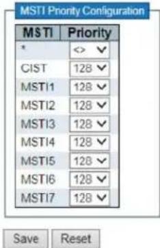
MSTI
The bridge instance. The CIST is the default instance, which is always active.
Priority
Controls the bridge priority. Lower numeric values have better priority. The bridge priority plus the MSTI instance number, concatenated with the 6-byte MAC address of the switch forms a Bridge Identifier.
2.10.4 CIST Ports
STP CIST Port Configuration
| CIST Aggregated Port Configuration | |||||||||
| Port | STP Enabled | Path Cost | Priority | Admin Edge | Auto Edge | Restricted | BPDU Guard | Point-to-point | |
| Role | TCN | ||||||||
| - | □ | Auto | 128 | Non-Edge | ☑ | □ | □ | □ | Forced True |
| Port | $TP Enabled | Path Cost | Priority | Admin Edge | Auto Edge | Restricted | BPDU Guard | Point-to-point | |||
| Role | TCN | ||||||||||
| * | □ | <> | ✓ | <> | <> | ✓ | □ | □ | □ | <> | |
| 1 | □ | Auto | ✓ | 128 | Non-Edge | ✓ | □ | □ | □ | Auto | |
| 2 | □ | Auto | ✓ | 128 | Non-Edge | ✓ | □ | □ | □ | Auto | |
| 3 | □ | Auto | ✓ | 128 | Non-Edge | ✓ | □ | □ | □ | Auto | |
| 4 | □ | Auto | ✓ | 128 | Non-Edge | ✓ | □ | □ | □ | Auto | |
| 5 | □ | Auto | ✓ | 128 | Non-Edge | ✓ | □ | □ | □ | Auto | |
| 6 | □ | Auto | ✓ | 128 | Non-Edge | ✓ | □ | □ | □ | Auto | |
| 7 | □ | Auto | ✓ | 128 | Non-Edge | ✓ | □ | □ | □ | Auto | |
| 8 | □ | Auto | ✓ | 128 | Non-Edge | ✓ | □ | □ | □ | Auto | |
| 9 | □ | Auto | ✓ | 128 | Non-Edge | ✓ | □ | □ | □ | Auto | |
| 10 | □ | Auto | ✓ | 128 | Non-Edge | ✓ | □ | □ | □ | Auto | |
| 11 | □ | Auto | ✓ | 128 | Non-Edge | ✓ | □ | □ | □ | Auto | |
| 12 | □ | Auto | ✓ | 128 | Non-Edge | ✓ | □ | □ | □ | Auto | |

STP CIST Port Configuration
Port
The switch port number of the logical STP port.
STP Enabled
Controls whether STP is enabled on this switch port.
Path Cost
Controls the path cost incurred by the port. The Auto setting will set the path cost as appropriate by the physical link speed, using the 802.1D recommended values. Using the Specific setting, a user-defined value can be entered. The path cost is used when establishing the active topology of the network. Lower path cost ports are chosen as forwarding ports in favour of higher path cost ports. Valid values are in the range 1 to 200000000.
Priority
Controls the port priority. This can be used to control priority of ports having identical port cost. (See above).
operEdge (state flag)
Operational flag describing whether the port is connecting directly to edge devices. (No Bridges attached). Transition to the forwarding state is faster for edge ports (having operEdgetrue) than for other ports. The value of this flag is based on AdminEdge and AutoEdge fields. This flag is displayed as Edge in Monitor->Spanning Tree -> STP Detailed Bridge Status.
AdminEdge
Controls whether the operEdge flag should start as set or cleared. (The initial operEdge state when a port is initialized).
AutoEdge
Controls whether the bridge should enable automatic edge detection on the bridge port. This allows operEdge to be derived from whether BPDU's are received on the port or not.
Restricted Role
If enabled, causes the port not to be selected as Root Port for the CIST or any MSTI, even if it has the best spanning tree priority vector. Such a port will be selected as an Alternate Port after the Root Port has been selected. If set, it can cause lack of spanning tree connectivity. It can be set by a network
administrator to prevent bridges external to a core region of the network influence the spanning tree active topology, possibly because those bridges are not under the full control of the administrator. This feature is also known as Root Guard.
Restricted TCN
If enabled, causes the port not to propagate received topology change notifications and topology changes to other ports. If set it can cause temporary loss of connectivity after changes in a spanning tree's active topology as a result of persistently incorrect learned station location information. It is set by a network administrator to prevent bridges external to a core region of the network, causing address flushing in that region, possibly because those bridges are not under the full control of the administrator or the physical link state of the attached LANs transits frequently.
BPDU Guard
If enabled, causes the port to disable itself upon receiving valid BPDU's. Contrary to the similar bridge setting, the port Edge status does not affect this setting.
A port entering error-disabled state due to this setting is subject to the bridge Port Error Recovery setting as well.
Point-to-Point
Controls whether the port connects to a point-to-point LAN rather than to a shared medium. This can be automatically determined, or forced either true or false. Transition to the forwarding state is faster for point-to-point LANs than for shared media.

Port
The switch port number of the corresponding STP CIST (and MSTI) port.
Path Cost
Controls the path cost incurred by the port. The Auto setting will set the path cost as appropriate by the physical link speed, using the 802.1D recommended values. Using the Specific setting, a user-defined value can be entered. The path cost is used when establishing the active topology of the network. Lower path cost ports are chosen as forwarding ports in favor of higher path cost ports. Valid values are in the range 1 to 200000000.
Priority
Controls the port priority. This can be used to control priority of ports having identical port cost. (See above).
2.10.5 MSTI Ports
IOMC Profile
2.11 IPMC Profile

2.11.1 Profile Table
IPMC Profile Configurations
Global Profile Mode Enabled
IPMC Profile Table Setting

Global Profile Mode The default is Disabled (disabled mode) and the enabled mode is Enabled.
- Click "Add New IPMC Profile" can add a new entry into the list.
• Profile Name: Enter the profile name.
• Profile Description: Enter a short description for this profile. - Click the "Save" button to save. Click the "Reset" button to cancel if enter again.
2.11.2 Address Entry
IPMC Profile Address Configuration
Navigate Address Entry Setting in IPMC Profile by 20 entries per page

• Entry Name: Enter a name for the index address entry table.
• Start Address: Enter the IPv4 or IPv6 multicast address used within this address range.
• End Address: Enter the ending IPv4 or IPv6 multicast address used within this address range.
- Click "Add New Address (Range) Entry" to insert a new entry.
- Click the "Save" button to save. Click the "Reset" button to cancel if enter again.
IPMC
2.12 IPMC
The IPMC menu includes the IGMP Snooping and its submenu. Select the appropriate menu to set up the detailed configuration.

2.12.1 IGMP Snooping
Internet Group Management Protocol (IGMP) is a telecommunication protocol that used to manage multicast group members of the Internet Protocol. IGMP is used by IP hosts and neighboring multicast routers to establish multicast group membership.
It can be used more effectively when supporting activities, such as online streaming videos and games. IGMP Snooping is the process of monitoring IGMP traffic. IGMP Snooping, as its name implies, it's a feature that allows "monitoring" in an IGMP session between a host and a router by processing Layer 3 packets of IGMP packets sent over the multicast network.
When IGMP Snooping is enabled in the switch, it analyzes all IGMP packets between the switch connected to the network and the host of the multicast router. When a switch receives an IGMP report from a given multicast group of the host, the switch adds the host's port number to the group's multicast list. When the departure of an IGMP is monitored by the switch, the switch will remove the host's port from the table entry. IGMP Snooping can be more effectively reduce multicast traffic for streaming media and other bandwidth-intensive IP applications. A switch that uses IGMP Snooping will only forward the multicast traffic to the host of this traffic. The switch is generated where it reduces multicast traffic and packet processing (it needs additional memory to handle multicast cost tables), and also reduces the workload of the host network card (or operating system) which does not accept and filter all multicast traffic networks.
2.12.1.1 Basic Configuration
2.12.1 IGMP Snooping
2.12.1.1 Basic Configuration
IGMP Snooping Configuration

Port Related Configuration
| Port | Router Port | Fast Leave | Throttling |
| - | O✓ | ||
| 1 | unlimited ✓ | ||
| 2 | unlimited ✓ | ||
| 3 | unlimited ✓ | ||
| 4 | unlimited ✓ | ||
| 5 | unlimited ✓ | ||
| 6 | unlimited ✓ | ||
| 7 | unlimited ✓ | ||
| 8 | unlimited ✓ | ||
| 9 | unlimited ✓ | ||
| 10 | unlimited ✓ | ||
| 11 | unlimited ✓ | ||
| 12 | unlimited ✓ |
Save Reset
IGMP Snooping Configuration
Snooping Enabled
Enable the Global IGMP Snooping.
Unregistered IPMCv4 Flooding Enabled
Enable unregistered IPMCv4 traffic flooding.
The flooding control takes effect only when IGMP Snooping is enabled.
When IGMP Snooping is disabled, unregistered IPMCv4 traffic flooding is always active in spite of this setting.
IGMP SSM Range
SSM (Source-Specific Multicast) Range allows the SSM-aware hosts and routers run the SSM service model for the groups in the address range.
Assign valid IPv4 multicast address as prefix with a prefix length (from 4 to 32) for the range.
Leave Proxy Enabled
Enable IGMP Leave Proxy. This feature can be used to avoid forwarding unnecessary leave messages to the router side.
Proxy Enabled
Enable IGMP Proxy. This feature can be used to avoid forwarding unnecessary join and leave messages to the router side.
- Port Related Configuration
Router Port
Specify which ports act as router ports. A router port is a port on the Ethernet switch that leads towards the Layer 3 multicast device or IGMP querier. If an aggregation member port is selected as a router port, the whole aggregation will act as a router port.
Fast Leave
Enable the fast leave on the port.
Throttling
Enable to limit the number of multicast groups to which a switch port can belong.
2.12.1.2 VLAN
Configuration

This page is to configured IGMP decretion of one port. Click "Add New IGMP VLAN" to add one new entry
Delete
Check to delete the entry. The designated entry will be deleted during the next save.
VLAN ID
The VLAN ID of the entry.
IGMP Snooping Enabled
Enable the per-VLAN IGMP Snooping. Up to 32 VLANs can be selected for IGMP Snooping.
Querier Election
Enable to join IGMP Querier election in the VLAN. Disable to act as an IGMP Non-Querier.
Querier Address
Define the IPv4 address as source address used in IP header for IGMP Querier election.
When the Querier address is not set, system uses IPv4 management address of the IP interface associated with this VLAN.
When the IPv4 management address is not set, system uses the first available IPv4 management address.
Otherwise, system uses a pre-defined value. By default, this value will be 192.0.2.1.
Compatibility
Compatibility is maintained by hosts and routers taking appropriate actions depending on the versions of IGMP operating on hosts and routers within a network.
The allowed selection is IGMP-Auto, Forced IGMPv1, Forced IGMPv2, Forced IGMPv3, default compatibility value is IGMP-Auto.
PRI
Priority of Interface.
It indicates the IGMP control frame priority level generated by the system. These values can be used to prioritize different classes of traffic.
The allowed range is 0 (best effort) to 7 (highest), default interface priority value is 0.
RV
Robustness Variable.
The Robustness Variable allows tuning for the expected packet loss on a network.
The allowed range is 1 to 255, default robustness variable value is 2.
QI
Query Interval.
The Query Interval is the interval between General Queries sent by the Querier.
The allowed range is 1 to 31744 seconds, default query interval is 125 seconds.
QRI
Query Response Interval.
The Maximum Response Delay used to calculate the Maximum Response Code inserted into the periodic General Queries.
The allowed range is 0 to 31744 in tenths of seconds; default query response interval is 100 in tenths of seconds (10 seconds).
LLQI (LMQI for IGMP)
Last Member Query Interval.
The Last Member Query Time is the time value represented by the Last Member Query Interval, multiplied by the Last Member Query Count.
The allowed range is 0 to 31744 in tenths of seconds, default last member query interval is 10 in tenths of seconds (1 second).
URI
Unsolicited Report Interval. The Unsolicited Report Interval is the time between repetitions of a host's initial report of membership in a group.
The allowed range is 0 to 31744 seconds; default unsolicited report interval is 1 second.
2.12.1.3 Port Filtering Profile
The Port Filtering Configuration page filters specific multicast traffic on a per-port basis. Before you can select a profile for filtering, you must set the profile structure on the IPMC Profile page.
IGMP Snooping Port Filtering Profile Configuration
| Port | Filtering Profile |
| 1 | |
| 2 | |
| 3 | |
| 4 | |
| 5 | |
| 6 | |
| 7 | |
| 8 | |
| 9 | |
| 10 | |
| 11 | |
| 12 |
Save Reset
• Port: device port number
• Filtering Profile: Select the configured multicast group that is rejected on one port. When a multicast group is selected on a port, will receive the IGMP connection report is deleted on the port.
- Click to check the details choose IPMC profile.
snooping, similar to IGMP snooping IPv4, for multicast communication over IPv6. In other words, MLD monitors the configuration port to restrict or control IPv6 multicast traffic in order to forward multicast traffic to the port (or user) that it wishes to receive. In this way, MLD monitoring can reduce the flood of IPv6 multicast packets on a given Vlan. Please note that IGMP snooping and MLD monitoring are independent of each other. They can be enabled or run at the same time.
2.12.2 MLD Snooping
MLD Snooping Configuration
| Global Configuration | |
| Snooping Enabled | |
| Unregistered IPMCv6 Flooding Enabled | ✓ |
| MLD SSM Range | f3e: / 96 |
| Leave Proxy Enabled | |
| Proxy Enabled | |
Port Related Configuration
| Port | Router Port | Fast Leave | Throttling |
| * | □ | □ | <> √ |
| 1 | □ | □ | unlimited √ |
| 2 | □ | □ | unlimited √ |
| 3 | □ | □ | unlimited √ |
| 4 | □ | □ | unlimited √ |
| 5 | □ | □ | unlimited √ |
| 6 | □ | □ | unlimited √ |
| 7 | □ | □ | unlimited √ |
| 8 | □ | □ | unlimited √ |
| 9 | □ | □ | unlimited √ |
| 10 | □ | □ | unlimited √ |
| 11 | □ | □ | unlimited √ |
| 12 | □ | □ | unlimited √ |
Save Reset
MLD Snooping Configuration
Snooping Enabled
Enable the Global MLD Snooping.
Unregistered IPMCv6 Flooding Enabled
Enable unregistered IPMCv6 traffic flooding.
The flooding control takes effect only when MLD Snooping is enabled.
When MLD Snooping is disabled, unregistered IPMCv6 traffic flooding is always active in spite of this setting.
MLD SSM Range
SSM (Source-Specific Multicast) Range allows the SSM-aware hosts and routers run the SSM service model for the groups in the address range.
Assign valid IPv6 multicast address as prefix with a prefix length (from 8 to 128) for the range.
Leave Proxy Enabled
Enable MLD Leave Proxy. This feature can be used to avoid forwarding unnecessary leave messages to the router side.
Proxy Enabled
Enable MLD Proxy. This feature can be used to avoid forwarding unnecessary join and leave messages to the router side.
Router Port
Specify which ports act as router ports. A router port is a port on the Ethernet switch that leads towards the Layer 3 multicast device or MLD querier.
If an aggregation member port is selected as a router port, the whole aggregation will act as a router port.
- Port Related Configuration
Router Port
Specify which ports act as router ports. A router port is a port on the Ethernet switch that leads towards the Layer 3 multicast device or MLD querier.
If an aggregation member port is selected as a router port, the whole aggregation will act as a router port.
Fast Leave
Enable the fast leave on the port.
Throttling
Enable to limit the number of multicast groups to which a switch port can belong.
2.12.2.2 VLAN Configuration
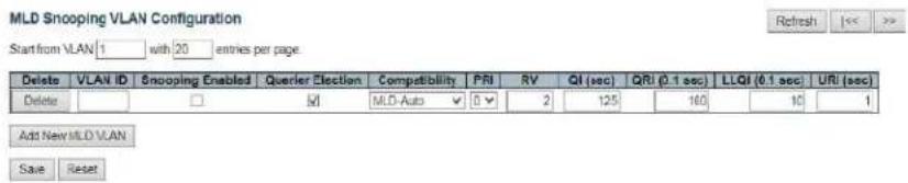
VLAN ID
The VLAN ID of the entry.
MLD Snooping Enabled
Enable the per-VLAN MLD Snooping. Up to 32 VLANs can be selected for MLD Snooping.
Querier Election
Enable to join MLD Querier election in the VLAN. Disable to act as a MLD Non-Querier.
Compatibility
Compatibility is maintained by hosts and routers taking appropriate actions depending on the versions of MLD operating on hosts and routers within a network. The allowed selection is MLD-Auto, Forced MLDv1, Forced MLDv2, default compatibility value is MLD-Auto.
PRI
Priority of Interface.
It indicates the MLD control frame priority level generated by the system. These values can be used to prioritize different classes of traffic.
The allowed range is 0 (best effort) to 7 (highest), default interface priority value is 0.
RV
Robustness Variable.
The Robustness Variable allows tuning for the expected packet loss on a link.
The allowed range is 1 to 255, default robustness variable value is 2.
QI
Query Interval.
The Query Interval is the interval between General Queries sent by the Querier.
The allowed range is 1 to 31744 seconds, default query interval is 125 seconds.
QRI
Query Response Interval.
The Maximum Response Delay used to calculate the Maximum Response Code inserted into the periodic General Queries.
The allowed range is 0 to 31744 in tenths of seconds; default query response interval is 100 in tenths of seconds (10 seconds).
LLQI
Last Listener Query Interval.
The Last Listener Query Interval is the Maximum Response Delay used to calculate the Maximum
Response Code inserted into Multicast Address Specific Queries sent in response to Version 1
Multicast Listener Done messages. It is also the Maximum Response Delay used to calculate the
Maximum Response Code inserted into Multicast Address and Source Specific Query messages.
The allowed range is 0 to 31744 in tenths of seconds; default last listener query interval is 10 in tenths of seconds (1 second).
URI
Unsolicited Report Interval.
The Unsolicited Report Interval is the time between repetitions of a node's initial report of interest in a multicast address.
The allowed range is 0 to 31744 seconds; default unsolicited report interval is 1 second.
Click to add one new entry.
The Port Filtering Configuration page filters specific multicast traffic on each port. Before you select a filtering profile for filtering purposes, must set up a profile on the IPMC Profile page.
2.12.2.3 Port Filtering Profile
MLD Snooping Port Filtering Profile Configuration
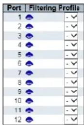

• Filtering Profile: Select the configured multicast group that is rejected on one port. When a multicast group is selected on a port, the MLD connection report received on the port is deleted.
- Click 🔴 to check the details of chosen IPMC profile.
2.13 LLDP

LLDP is a proximity discovery protocol. It defines a standard way for Ethernet network devices, such as switches, routers, and WLAN access points, to advertise their presence to other nodes in the network and to store discovery information for neighboring devices. Details such as device configuration and device identification can be advertised using this protocol. Specifically, LLDP defines a general announcement information set, a protocol for transmitting announcements, and a method for storing received announcement information. A device that advertises its own information may transmit multiple pieces of announcement information in a LAN packet, in the form of a Type Length Value (TLV) field.
LLDP is a one-way protocol. An LLDP agent can send its own system status and its own functions through the associated MSAP, and can also receive the current system status and functions of neighboring devices. However, the LLDP agent cannot request any information from the other party through this protocol. The LLDP proxy does not affect the sending and receiving of information. It can be configured to implement only the sending or receiving functions, or both.
2.13.1 LLDP
LLDP Configuration
LLDP Parameters
| Tx Interval | 30 | seconds |
| Tx Hold | 4 | times |
| Tx Delay | 2 | seconds |
| Tx Reinit | 2 | seconds |
LLDP Interface Configuration
| Interface | Mode | CDP aware | Optional TLYs | ||||
| Port Descr | Sys Name | Sys Descr | Sys Capa | Mgmt Addr | |||
| ○ √ | √ | √ | √ | √ | √ | ||
| GigabitEthernet 1/1 | Enabled √ | √ | √ | √ | √ | √ | |
| GigabitEthernet 1/2 | Enabled √ | √ | √ | √ | √ | √ | |
| GigabitEthernet 1/3 | Enabled √ | √ | √ | √ | √ | √ | |
| GigabitEthernet 1/4 | Enabled √ | √ | √ | √ | √ | √ | |
| GigabitEthernet 1/5 | Enabled √ | √ | √ | √ | √ | √ | |
| GigabitEthernet 1/6 | Enabled √ | √ | √ | √ | √ | √ | |
| GigabitEthernet 1/7 | Enabled √ | √ | √ | √ | √ | √ | |
| GigabitEthernet 1/8 | Enabled √ | √ | √ | √ | √ | √ | |
| GigabitEthernet 1/9 | Enabled √ | √ | √ | √ | √ | √ | |
| GigabitEthernet 1/10 | Enabled √ | √ | √ | √ | √ | √ | |
| 2.5GigabitEthernet 1/1 | Enabled √ | √ | √ | √ | √ | √ | |
| 2.5GigabitEthernet 1/2 | Enabled √ | √ | √ | √ | √ | √ | |
Save Reset
Tx Interval
The switch periodically transmits LLDP frames to its neighbors for having the network discovery information up-to-date. The interval between each LLDP frame is determined by the Tx Interval value. Valid values are restricted to 5 - 32768 seconds.
Tx Hold
Each LLDP frame contains information about how long time the information in the LLDP frame shall be considered valid. The LLDP information valid period is set to Tx Hold multiplied by Tx Interval seconds. Valid values are restricted to 2 - 10 times.
Tx Delay
If some configuration is changed (e.g. the IP address) a new LLDP frame is transmitted, but the time between the LLDP frames will always be at least the value of Tx Delay seconds. Tx Delay cannot be larger than 1/4 of the Tx Interval value. Valid values are restricted to 1 - 8192 seconds.
Tx Reinit
When an interface is disabled, LLDP is disabled or the switch is rebooted, a LLDP shutdown frame is transmitted to the neighboring units, signaling that the LLDP information isn't valid anymore. Tx Reinit controls the number of seconds between the shutdown frame and a new LLDP initialization. Valid values are restricted to 1 - 10 seconds.
Interface
The switch interface name of the logical LLDP interface.
Mode
Select LLDP mode.
• Rx only the switch will not send out LLDP information, but LLDP information from neighbor units is analyzed.
• Tx only the switch will drop LLDP information received from neighbors, but will send out LLDP information.
• Disabled The switch will not send out LLDP information, and will drop LLDP information received from neighbors.
• Enabled The switch will send out LLDP information, and will analyze LLDP information received from neighbors.
CDP Aware
Select CDP awareness.
The CDP operation is restricted to decoding incoming CDP frames (The switch doesn't transmit CDP frames). CDP frames are only decoded if LLDP on the interface is enabled.
Only CDP TLVs that can be mapped to a corresponding field in the LLDP neighbors' table are decoded. All other TLVs are discarded (Unrecognized CDP TLVs and discarded CDP frames are not shown in the LLDP statistics.). CDP TLVs are mapped onto LLDP neighbors' table as shown below. CDP TLV "Device ID" is mapped to the LLDP "Chassis ID" field.
CDP TLV "Address" is mapped to the LLDP "Management Address" field. The CDP address TLV can contain multiple addresses, but only the first address is shown in the LLDP neighbors table. CDP TLV "Port ID" is mapped to the LLDP "Port ID" field.
CDP TLV "Version and Platform" is mapped to the LLDP "System Description" field. Both the CDP and LLDP support "system capabilities", but the CDP capabilities cover capabilities that are not part of the LLDP. These capabilities are shown as "others" in the LLDP neighbors' table. If all interfaces have CDP awareness disabled the switch forwards CDP frames received from neighbor devices. If at least one interface has CDP awareness enabled all CDP frames are terminated by the switch.
Note: When CDP awareness on an interface is disabled the CDP information isn't removed immediately, but gets removed when the hold time is exceeded.
Port Descr
Optional TLV: When checked the "port description" is included in LLDP information transmitted.
Sys Name
Optional TLV: When checked the "system name" is included in LLDP information transmitted.
Sys Descr
Optional TLV: When checked the "system description" is included in LLDP information transmitted.
Sys Capa
Optional TLV: When checked the "system capability" is included in LLDP information transmitted.
Mgmt Addr
Optional TLV: When checked the "management address" is included in LLDP information transmitted.
2.13.2 LLDP-MED Configuration
LLDP-MED Configuration
Fast Start Repeat Count
Fast start repeat count 4
Transmit TLVs
| Interface | Capabilities | Policies | Location | PoE |
| ☑ | ☑ | ☑ | ☑ | |
| GigabitEthernet 1/1 | ☑ | ☑ | ☑ | ☑ |
| GigabitEthernet 1/2 | ☑ | ☑ | ☑ | ☑ |
| GigabitEthernet 1/3 | ☑ | ☑ | ☑ | ☑ |
| GigabitEthernet 1/4 | ☑ | ☑ | ☑ | ☑ |
| GigabitEthernet 1/5 | ☑ | ☑ | ☑ | ☑ |
| GigabitEthernet 1/6 | ☑ | ☑ | ☑ | ☑ |
| GigabitEthernet 1/7 | ☑ | ☑ | ☑ | ☑ |
| GigabitEthernet 1/8 | ☑ | ☑ | ☑ | ☑ |
| GigabitEthernet 1/9 | ☑ | ☑ | ☑ | ☑ |
| GigabitEthernet 1/10 | ☑ | ☑ | ☑ | ☑ |
| 2.5GigabitEthernet 1/1 | ☑ | ☑ | ☑ | ☑ |
| 2.5GigabitEthernet 1/2 | ☑ | ☑ | ☑ | ☑ |
Coordinates Location
Latitude 0 North Longitude 0 East Altitude 0 Meters Map Datum WGS4
Civic Address Location
| Country code | State | County | ||||
| City | City district | Block (Neighborhood) | ||||
| Street | Leading street direction | Trailing street suffix | ||||
| Street suffix | House no. | House no. suffix | ||||
| Landmark | Additional location info | Name | ||||
| Zip code | Building | Apartment | ||||
| Floor | Room no. | Place type | ||||
| Postal community name | P.O. Box | Additional code | ||||
Emergency Call Service
Emergency Call Service
Policies
Delete Policy ID Application Type Tag VLAN ID L2 Priority DSCP No entries present
Add New Policy
• Fast Start Repeat count: Quick Start and Emergency Call Service Location Identification Discovering endpoints is a critical aspect of VoIP systems.
In addition, it is best to have only that information that advertises, especially with regard to specific endpoint types (for example, only advertising voice network policies allow devices), in order to save limited LLDPU space and reduce security and system integrity issues. With this in mind, LLDP-MED defines a quick-start interaction between the protocol and the application layer to implement these related attributes.
With Quick Start Repeat Count, you can specify the number of quick starts transfer repetitions. The recommended value is 4 times. When the LLDP framework for new information is received, the 4 LLDP frame will be transmitted and a 1 second interval will be transmitted too.
It is worth noting that the LLDP-MED and LLDP-MED fast-start mechanisms are only suitable for running on links between LLDP-MED network-connected devices and endpoint devices, and therefore do not apply to links between LAN infrastructure elements, including Network connected devices, or other types of links.
- Coordinates Location
Latitude: The latitude should be normalized to 0-90 degrees and the maximum is 4 digits. You can specify the direction north of the equator or south of the equator.
○ Longitude: The longitude should be normalized to 0-180 degrees with a maximum of 4 digits. You can specify the direction on the east side of the main meridian or on the west side of the meridian.
Altitude: The height should be between -32767 and 32767, with a maximum of 4 digits. You can choose between two height types (ground or meter).
- Meters: representing the height defined by the vertical datum.
Map Datum: The altitude is represented by the height of a building different from the ground. Even if it is outside the building, height = 0 makes sense, And the ground level is represented on a given latitude and longitude.
- Inside the building, 0 represents the main entrance associated with the ground level.
Map datum: The map data is used for the coordinates given in these options: WGS84: (Geography 3D) - World Geodesic System 1984, CRS Code 4327, Main Meridian Name: Greenwich.
- nad83/navd88: North American benchmark 1983, CRS code 4269, main meridian name: Greenwich; related vertical data is North American vertical data (NAVD88) in 1988.
This baseline pair will be used when referring to a location on land rather than to tidal waters (using baseline = NAD83/MLLW).
- NAD83/MLLW: North American benchmark 1983, CRS code 4269, whose real name is Meridian; Greenwich;
The associated vertical reference is the low water level (MLLW). This reference pair will be used when referring to the location of the water/ocean.
• Civic Address Location
- IETF Geopriv address-based location configuration information (citizen address LCI).
Country code: Two-letter ISO 3166 country code, uppercase ASCII letters - examples: DK, DE or US.
o Stat: National sub-division (state, state, district, province, county).
○ County: County, parish, gun (Japan), district.
City: City, Township, Stone (Japan) - Example: Copenhagen.
City district: City partition, district, district, district, week (Japan).
○ Block(Neighborhood): Block, block.
- Street: Street - example: Poppelvej.
○ Leading street direction : example: n.
- Trailing street suffi: example: SW.
○ Street suffix: example: Ave, Platz.
○ House no.: example: 21.
House no. suffix: example: 1/2。
Landmark: Landmarks or Vanity Fair, such as Columbia University.
○ Additional location info: example: South Wing.
Name: Name (residence and office occupants): For example: Flemming Jahn.
- Zip code: Zip code/ Zip code - example:2791.
○ Building: building structure. For example: low library.
○ Apartment: Unit (apartment suite). For example: 42.
- Floor: for example: 4.
- Room no.: for example: 450 f.
- Place typ: for example: office.
o Community's name(Postal community name: Leonia.
o P.O. Box: for example: 12345.
○ Additional code: for example: 1320300003.
- Additional code
○ Additional code: Emergency call services (such as E911, etc.), such as the definition of TIA or NENA.
- Policies
- Policy ID: Specify an ID for the Policy.
Application Type: Application types include "voice", "voice signal", "guest voice", "guest voice signal",
o "Softphone Voice", "Video Conferencing", "Streaming Media", "Video Signal". - Tag: The tag indicates whether the specified application type uses a "marked" or "unlabeled" VLAN.标
o VLAN ID: Specifies the VLAN ID of the port.
○ (L2 Priority: Specify one of eight priority levels (0-7), defined as 802.1D-2004. - DSCP: Specify 64 code point values (0-63) as defined in IETF RFC 2474.
2.14 PoE
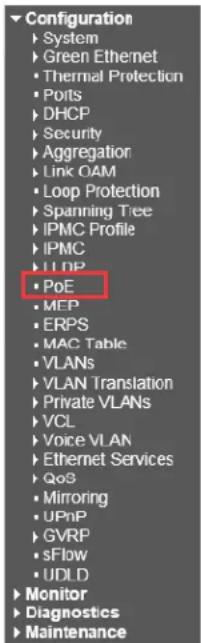
Power Over Ethernet Configuration

PoE Power Supply Configuration

PoE Port Configuration
| Port | PoE Mode | Priority | Maximum Power [W] | Time Delay [s] |
| * | <>✓ | <>✓ | 40 | 600 |
| 1 | PoE+✓ | High✓ | 40 | 600 |
| 2 | PoE+✓ | High✓ | 40 | 600 |
| 3 | PoE+✓ | High✓ | 40 | 600 |
| 4 | PoE+✓ | High✓ | 40 | 600 |
| 5 | PoE+✓ | High✓ | 90 | 600 |
| 6 | PoE+✓ | High✓ | 40 | 600 |
| 7 | PoE+✓ | High✓ | 90 | 600 |
| 8 | PoE+✓ | High✓ | 40 | 600 |

Reserved Power determined by: There are three modes for configuring how the ports/PDs may reserve power.
- Allocated mode: In this mode the user allocates the amount of power that each port may reserve. The allocated/reserved power for each port/PD is specified in the Maximum Power fields.
- Actual Consumption: In this mode the ports are shut down when the actual power consumption for all ports exceeds the amount of power that the maximum power supply can deliver or if the actual power consumption for a given port exceeds the maximum power for that port. The ports are shut down according to the port's priority. If two ports have the same priority the port with the highest port number is shut down.
- Reserved Power: Close Port Priority Function Same as Actual Consumption
- PoE Power Supply Configuration: For being able to determine the amount of power the PD may use, it must be defined what amount of power a power source can deliver. Valid values are in the range 0 to 480 Watts.
- PoE Port Configuration:
- Port: This is the logical port number for this row. Ports that are not PoE-capable are grayed out and thus impossible to configure PoE for.
A. PoE Mode: The PoE Mode represents the PoE operating mode for the port.
I. Disabled: PoE disabled for the port.
B. PoE : Enables PoE IEEE 802.3af (Class 3 PDs limited to 15.4W)
C. PoE+ : Enables PoE+ IEEE 802.3bt(at) (Class 1-8 PSE 30-90W/Class 8 PD 71W)
D. Start up and detection times can differ between different cameras. It is recommended Delay time not exceed 300 seconds. Greater duration may result in PoE errors
Priority: The Priority represents the ports priority. There are three levels of power priority named Low, High and Critical. The priority is used in the case where the remote devices require more power than the power supply can deliver. In this case the port with the lowest priority will be turn off starting from the port with the highest port number.
Maximum Power: The Maximum Power value contains a numerical value that indicates the maximum power in watts that can be delivered to a remote device.
The maximum allowed value is 90 W.
Time Delay: The Time Delay value contains a numerical value that indicates the poe delay in time that can be delivered to a remote device. The maximum allowed value is 600 S.
Power Over Ethernet Status:
Power Over Ethernet Status
| Local Port | PD class | Power Allocated | Power Used | Current Used | Voltage Used | Priority | Port Status |
| 1 | - | 0 [W] | 0 [W] | 0 [mA] | 0 [V] | Low | No PD detected |
| 2 | - | 0 [W] | 0 [W] | 0 [mA] | 0 [V] | Low | No PD detected |
| 3 | - | 0 [W] | 0 [W] | 0 [mA] | 0 [V] | Low | No PD detected |
| 4 | - | 0 [W] | 0 [W] | 0 [mA] | 0 [V] | Low | No PD detected |
| 5 | 0 | 75 [W] | 66 [W] | 1375 [mA] | 48 [V] | Low | Post turned ON |
| 6 | - | 0 [W] | 0 [W] | 0 [mA] | 0 [V] | Low | No PD detected |
| 7 | - | 0 [W] | 0 [W] | 0 [mA] | 0 [V] | Low | No PD detected |
| 8 | - | 0 [W] | 0 [W] | 0 [mA] | 0 [V] | Low | No PD detected |
| Total | 75 [W] | 66 [W] | 1375 [mA] |
MEP
2.15 MEP
Configuration
Configuration
▶ System
▶ Green Ethernet
- Thermal Protection
- Ports
DHCP
▶ Security
Aggregation
▶ Link OAM
- Loop Protection
▶ Spanning Tree
IPMC Profile
▶IPMC
▶LDP
- PoE
-MEP
- ERPS
- MAC Table
Maintenance Entity Point
| Delete | Instance | Domain | Mode | Direction | Residence Port | Level | Flow instance | Tagged VID | This MAC | Alarm |
| 1 | Port | Mep | Down | 9 | 0 | 100 | 00-79-67-D1-00-CA | |||
| Delete | 2 | Port | Mep | Down | 10 | 0 | 10 | 100 |
Add New ME
Save
Reset
ERPS
2.16 ERPS
Configuration

Ethernet Ring Protection Switching
Refresh
| Delete | ERP'S ID | Port 0 | Port 1 | Port 0 APS MEP | Port 1 APS MEP | Port 0 SF MEP | Port 1 SF MEP | Ring Type | Interconnected Node | Virtual Channel | Major Ring ID | Alarm |
| Delete | 1 | 1 | 1 | 1 | 1 | 1 | 1 | Major √ | □ | □ | 0 | |
| Add New Protection Group | Save | Reset | ||||||||||
When configuring the ERPS protocol, keep at least one link disconnected until all ring nodes are configured. mTurning on the ring network without all nodes configured will easily cause broadcast storms. The ring network protection protocol does not support simultaneous operation with multiple spanning tree protocols (MSTP). MSTP will not start when EAPS or ERPS is configured.
Please refer to Appendix 3 for detailed configuration.
2.17 MAC Table
Configuration
2.17 MAC Table Configuration
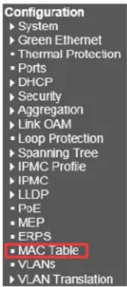
To apply a MAC access list to a port, you must first create a MAC access list. When a MAC access list is successfully created, it enters the MAC access-list configuration mode, in which the MAC access-list entries can be configured.
MAC Address Table Configuration
Aging Configuration
| Disable Automatic Aging | |
| Aging Time | 300 seconds |
MAC Table Learning
Static MAC Table Configuration
| Port Members | |||||||||||||
| Delete | VLAN ID | MAC Address | 1 | 2 | 3 | 4 | 5 | 6 | 7 | 8 | 9 | 10 | 11 |
| Add New Static Entry | |||||||||||||
| Save | Reset | ||||||||||||
- Aging Configuration
- Set a timeout for entries in the dynamic MAC table. By default, dynamic entries are removed from the MAC table after 300 seconds.
This removal is also known as aging. The aging time is configured by entering a value in a few seconds; the allowed range is 10 to 1000000 seconds.
• MAC Table Learning. Disable automatic aging of dynamic entries by checking to disable automatic aging.
If the learning mode for a given port is eliminated, another module will control the mode so that the user cannot change it.
- An example of such a module is mac-based authentication, under 802.1 x.
○ Each port learns according to the following settings:
■ Auto: Once an unknown SMAC is received, the learning is done automatically.
■ Disable: It is done without learning.
- Secure: Only static MAC entries are learned and all other frames are deleted.
Note: Make sure that the link to manage the switch is added to the static Mac table before switching to secure learning mode, otherwise the management link will be lost and can only be restored by using another non-secure port or by connecting to the switch via the serial interface.
• Static MAC Table Configuration
Configure a static MAC table here. Click "Add New Static Entry" to add an entry. Click "Save" to save the configuration. Click "Reset" Undo or Reconfigure.

2.18 VLANs
Please refer to Appendix 2 for detailed configuration.
2.19 GLOBAL VLAN CONFIGURATION
Global VLAN Configuration
| Allowed Access VLANs | 1 |
| Ethertype for Custom S-ports | 99A2 |
Port VLAN Configuration
| Port | Mode | Port VLAN | Port Type | Ingress Filtering | Ingress Acceptance | Egress Tagging | Allowed VLANs | Forbidden VLANs |
| 1 | 1 | |||||||
| 1 | Access | C-Port | Tagged and Untagged | Untag All | ||||
| 2 | Access | C-Port | Tagged and Untagged | Untag All | ||||
| 3 | Access | C-Port | Tagged and Untagged | Untag All | ||||
| 4 | Access | C-Port | Tagged and Untagged | Untag All | ||||
| 5 | Access | C-Port | Tagged and Untagged | Untag All | ||||
| 6 | Access | C-Port | Tagged and Untagged | Untag All | ||||
| 7 | Access | C-Port | Tagged and Untagged | Untag All | ||||
| 8 | Access | C-Port | Tagged and Untagged | Untag All | ||||
| 9 | Access | C-Port | Tagged and Untagged | Untag All | ||||
| 10 | Access | C-Port | Tagged and Untagged | Untag All | ||||
| 11 | Access | C-Port | Tagged and Untagged | Untag All | ||||
| 12 | Access | C-Port | Tagged and Untagged | Untag All |
Save Reset
Allowed Access VLANs
This field shows the allowed Access VLANs, i.e. it only affects ports configured as Access ports. Ports in other modes are members of the VLANs specified in the Allowed VLANs field. By default, only VLAN 1 is enabled. More VLANs may be created by using a list syntax where the individual elements are separated by commas. Ranges are specified with a dash separating the lower and upper bound. The following example will create VLANs 1, 10, 11, 12, 13, 200, and 300: 1,10-13,200,300. Spaces are allowed in between the delimiters.
Ethertype for Custom S-ports
This field specifies the ethertype/TPID (specified in hexadecimal) used for Custom S-ports. The setting is in force for all ports whose Port Type is set to S-Custom-Port.
Port
This is the logical port number of this row.
Mode
The port mode (default is Access) determines the fundamental behavior of the port in question. A port can be in one of three modes as described below. Whenever a particular mode is selected, the remaining fields in that row will be either grayed out or made changeable depending on the mode in question. Grayed out fields show the value that the port will get when the mode is applied.
Access:
Access ports are normally used to connect to end stations. Dynamic features like Voice VLAN may add the port to more VLANs behind the scenes. Access ports have the following characteristics:
• Member of exactly one VLAN, the Port VLAN (a.k.a. Access VLAN), which by default is 1
• Accepts untagged and C-tagged frames
• Discards all frames not classified to the Access VLAN
• On egress all frames are transmitted untagged
Trunk:
Trunk ports can carry traffic on multiple VLANs simultaneously, and are normally used to connect to other switches. Trunk ports have the following characteristics:
By default, a trunk port is member of all VLANs (1-4095)
• The VLANs that a trunk port is member of may be limited by the use of Allowed VLANs
• Frames classified to a VLAN that the port is not a member of are discarded
- By default, all frames but frames classified to the Port VLAN (a.k.a. Native VLAN) get tagged on egress. Frames classified to the Port VLAN do not get C-tagged on egress
• Egress tagging can be changed to tag all frames, in which case only tagged frames are accepted on ingress
Hybrid:
Hybrid ports resemble trunk ports in many ways, but adds additional port configuration features. In addition to the characteristics described for trunk ports, hybrid ports have these abilities:
• Can be configured to be VLAN tag unaware, C-tag aware, S-tag aware, or S-custom-tag aware
• Ingress filtering can be controlled
• Ingress acceptance of frames and configuration of egress tagging can be configured independently
Port VLAN
Determines the port's VLAN ID (a.k.a. PVID). Allowed VLANs are in the range 1 through 4095, default being 1.
On ingress, frames get classified to the Port VLAN if the port is configured as VLAN unaware, the frame is untagged, or VLAN awareness is enabled on the port, but the frame is priority tagged (VLAN ID = 0).
On egress, frames classified to the Port VLAN do not get tagged if Egress Tagging configuration is set to untag Port VLAN.
The Port VLAN is called an "Access VLAN" for ports in Access mode and Native VLAN for ports in Trunk or Hybrid mode.
Port Type
Ports in hybrid mode allow for changing the port type, that is, whether a frame's VLAN tag is used to classify the frame on ingress to a particular VLAN, and if so, which TPID it reacts on. Likewise, on egress, the Port Type determines the TPID of the tag, if a tag is required.
Unaware:
On ingress, all frames, whether carrying a VLAN tag or not, get classified to the Port VLAN, and possible tags are not removed on egress.
C-Port:
On ingress, frames with a VLAN tag with TPID = 0x8100 get classified to the VLAN ID embedded in the tag.
If a frame is untagged or priority tagged, the frame gets classified to the Port VLAN.
If frames must be tagged on egress, they will be tagged with a C-tag.
S-Port:
On egress, if frames must be tagged, they will be tagged with an S-tag.
On ingress, frames with a VLAN tag with TPID = 0x88A8 get classified to the VLAN ID embedded in the tag.
Priority-tagged frames are classified to the Port VLAN.
If the port is configured to accept Tagged Only frames (see Ingress Acceptance below), frames without this TPID are dropped.
Notice:
If the S-port is configured to accept Tagged and Untagged frames (see Ingress Acceptance below), frames with a C-tag are treated like frames with an S-tag.
If the S-port is configured to accept Untagged Only frames, S-tagged frames will be discarded (except for priority S-tagged frames). C-tagged frames are initially considered untagged and will therefore not be discarded. Later on in the ingress classification process, they will get classified to the VLAN embedded in the tag instead of the port VLAN ID.
S-Custom-Port:
On egress, if frames must be tagged, they will be tagged with the custom S-tag.
On ingress, , frames with a VLAN tag with a TPID equal to the Ethertype configured for Custom-S ports get classified to the VLAN ID embedded in the tag.
Priority-tagged frames are classified to the Port VLAN.
If the port is configured to accept Tagged Only frames (see Ingress Acceptance below), frames without this TPID are dropped.
Notice:
If the custom S-port is configured to accept Tagged and Untagged frames (see Ingress Acceptance below), frames with a C-tag are treated like frames with a custom S-tag.
If the Custom S-port is configured to accept Untagged Only frames, custom S-tagged frames will be discarded (except for priority custom S-tagged frames). C-tagged frames are initially considered untagged and will therefore not be discarded. Later on in the ingress classification process, they will get classified to the VLAN embedded in the tag instead of the port VLAN ID.
Hybrid:
Hybrid ports resemble trunk ports in many ways, but adds additional port configuration features. In addition to the characteristics described for trunk ports, hybrid ports have these abilities:
• Can be configured to be VLAN tag unaware, C-tag aware, S-tag aware, or S-custom-tag aware
• Ingress filtering can be controlled
- Ingress acceptance of frames and configuration of egress tagging can be configured independently
Port VLAN
Determines the port's VLAN ID (a.k.a. PVID). Allowed VLANs are in the range 1 through 4095, default being 1.
On ingress, frames get classified to the Port VLAN if the port is configured as VLAN unaware, the frame is untagged, or VLAN awareness is enabled on the port, but the frame is priority tagged (VLAN ID = 0).
On egress, frames classified to the Port VLAN do not get tagged if Egress Tagging configuration is set to untag Port VLAN.
The Port VLAN is called an "Access VLAN" for ports in Access mode and Native VLAN for ports in Trunk or Hybrid mode.
Port Type
Ports in hybrid mode allow for changing the port type, that is, whether a frame's VLAN tag is used to classify the frame on ingress to a particular VLAN, and if so, which TPID it reacts on. Likewise, on egress, the Port Type determines the TPID of the tag, if a tag is required.
Unaware:
On ingress, all frames, whether carrying a VLAN tag or not, get classified to the Port VLAN, and possible tags are not removed on egress.
C-Port:
On ingress, frames with a VLAN tag with TPID = 0x8100 get classified to the VLAN ID embedded in the tag.
If a frame is untagged or priority tagged, the frame gets classified to the Port VLAN.
If frames must be tagged on egress, they will be tagged with a C-tag.
S-Port:
On egress, if frames must be tagged, they will be tagged with an S-tag.
On ingress, frames with a VLAN tag with TPID = 0x88A8 get classified to the VLAN ID embedded in the tag.
Priority-tagged frames are classified to the Port VLAN.
If the port is configured to accept Tagged Only frames (see Ingress Acceptance below), frames without this TPID are dropped.
Notice:
If the S-port is configured to accept Tagged and Untagged frames (see Ingress Acceptance below), frames with a C-tag are treated like frames with an S-tag.
If the S-port is configured to accept Untagged Only frames, S-tagged frames will be discarded (except for priority S-tagged frames). C-tagged frames are initially considered untagged and will therefore not be discarded. Later on in the ingress classification process, they will get classified to the VLAN embedded in the tag instead of the port VLAN ID.
S-Custom-Port:
On egress, if frames must be tagged, they will be tagged with the custom S-tag.
On ingress, frames with a VLAN tag with a TPID equal to the Ethertype configured for Custom-S ports get classified to the VLAN ID embedded in the tag.
Priority-tagged frames are classified to the Port VLAN.
If the port is configured to accept Tagged Only frames (see Ingress Acceptance below), frames without this TPID are dropped.
Notice:
If the custom S-port is configured to accept Tagged and Untagged frames (see Ingress Acceptance below), frames with a C-tag are treated like frames with a custom S-tag.
If the Custom S-port is configured to accept Untagged Only frames, custom S-tagged frames will be discarded (except for priority custom S-tagged frames). C-tagged frames are initially considered untagged and will therefore not be discarded. Later on in the ingress classification process, they will get classified to the VLAN embedded in the tag instead of the port VLAN ID.
VLAN switching is especially useful for users who want to convert the original VLAN ID to a new VLAN ID to exchange data between different VLANs and improve VLAN expansion.
VLAN conversion replaces incoming c-VLAN tags with s-VLAN tags instead of adding extra tags. When configuring VLAN translation, both ends of the link must usually be able to properly replace the tag.
In other words, both endpoints must be configured to properly convert the c-vlan tag to the s-vlan tag and the s-vlan tag to the c-vlan tag in the network.
Note that only the access port supports VLAN translation. It is not recommended to configure VLAN translation on the trunk port. The "VLAN Conversion" menu contains the following submenus. Choose the appropriate configuration settings or view their status.
VLAN Translation
2.18 VLAN Translation

2.18.1 Port to Group Configuration
VLAN Translation Port Configuration
| Port | Group Configuration | |
| Default | Group ID | |
| * | □ | <> √ |
| 1 | □ | 1 √ |
| 2 | □ | 2 √ |
| 3 | □ | 3 √ |
| 4 | □ | 4 √ |
| 5 | □ | 5 √ |
| 6 | □ | 6 √ |
| 7 | □ | 7 √ |
| 8 | □ | 8 √ |
| 9 | □ | 9 √ |
| 10 | □ | 10 √ |
| 11 | □ | 11 √ |
| 12 | □ | 12 √ |
Save Reset
• Port: Device port number. "*" means that the configuration applies to all ports.
- Group Configuration: Cluster settings. The cluster settings are turned off by default and can be enabled by clicking the checkbox.
• Group ID: The default corresponds to the port number. Click the mouse down to change the corresponding value, the range is 1-10.
VLAN Translation Mappings
2.19.2 VLAN
Translation Mappings
VLAN Translation Mapping Table

flowchart
graph LR
    A["Group ID"] --> B["+"]
    C["Group ID"] --> D["1"]
    E["Group ID"] --> F["1"]
    G["Group ID"] --> H["2"]
    I["Group ID"] --> J["+"]
• Group ID: Represents the group ID that is applied to this conversion rule.
• VID: Indicates that it will be mapped to a new VLAN ID.
• TVID: Indicates that the Translation VLAN ID will be changed.
- Click the "⊕" button once to add a new entry. As shown below
- Click the Save button to save, click the reset button to reset, click the Cancel button to cancel.
Private VLAN
2.20 Private VLAN

2.20.1 Membership
Private VLAN Membership Configuration

This page is used to configure a private VLAN. You can add a new private VLAN here, you can modify the existing VLAN. The private VLAN is based on the source port mask and has no connection to the VLAN, which means that the VLAN id and private VLAN id can be the same. The port must be a member of the VLAN and private VLAN to be able to forward packets. By default, all ports are unknown to the VLAN and are members of VLAN 1 and private VLAN 1. A port that the VLAN does not know can only be a member of a VLAN, but it can be a member of multiple private VLANs.
• PVLAN ID: Specifies the PVLAN ID, which is called PVID. Valid values are 1 to 8.
• Port Members: Select the checkbox, if you want a port to belong to a private VLAN, cancel checkbox and remove a port from a private VLAN.
• Add New Private VLAN: Click button once to add a new VLAN entry.
- Save: After clicking the "Save" button, the member changes of the VLAN will be saved and the new VLAN will be enabled.
- Reset: Click the "Reset" button to clear all unsaved VLAN settings and changes.
2.20.2 port Isolation
Port Isolation Configuration

Private VLANs are used to group ports to prevent communication in the PVLAN. Port isolation is used to prevent communication between client ports in the same private VLAN.
A port isolated from others cannot forward any single, multicast, or broadcast traffic to any other port in the same PVLAN. Provide a check box for each port of a private VLAN.
Port isolation is enabled on this port when checking. If not restricted, port isolation is disabled on this port. By default, port isolation is disabled on all ports.
2.21.2
Protocol-based VLAN
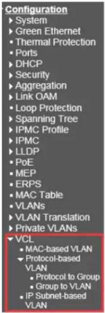
The MAC-based VLAN configuration page is based on the source MAC address setting VLAN. When a port receives an untagged frame, the source MAC address is processed to determine which VLAN these unmarked frames belong to.
When the source MAC address does not match the created rule, the untagged frame is assigned to the local VLAN ID (PVID) of the receiving port.
2.21.2.1 Protocol to Group
MAC-based VLAN Membership Configuration
| Port Members | ||||||||||||||
| Delete | MAC Address | VLAN ID | 1 | 2 | 3 | 4 | 5 | 6 | 7 | 8 | 9 | 10 | 11 | 12 |
| Currently no entries present | ||||||||||||||
| Add New Entry | ||||||||||||||
| Save | Reset | |||||||||||||
• MAC address: Indicates the source MAC address. Note that the source MAC address can only be mapped to one VLAN ID.
• VLAN ID: Map this MAC address to the associated VLAN ID.
• Port Members: The port that belongs to this VLAN. For the 8GbE+2 SFP, it shows 10 ports.
- Click "Add New Entry" Create a new rule.
- Click "Save" The changes will be saved and the newly entered rules will be enabled after clicking the "Save" button.
- Click "Reset" Restore the default configuration.
• Network devices required to support multiple protocols cannot simply be grouped into a common VLAN. This may require non-standard devices to pass traffic between different vlans to include all devices participating in a particular protocol. This configuration leaves users without the basic benefits of VLANs, including security and accessibility. To avoid these problems, you can configure this switch using a protocol-based VLAN that divides the
physical network into logical VLAN groups for each required protocol. When a frame is received on a port, its VLAN members can be determined based on the type of protocol used by the inbound packet.
Protocol to Group Mapping Table

• Frame Type: There are three types of frameworks to choose from; these are "Ethernet", "SNAP" and "LLC".
- Ethernet: ether type (etype) value. By default, it is set to 0x0800. The allowed range is 0x0600 to 0xffff.
• SNAP: This includes the OUI (Organization's Unique Identifier) and PID (Protocol ID) values.
• LLC: A value in the xx-x-xx format, each pair (xx) in the string is a hexadecimal value in the range 0x00-0xff.
• f the pair is hex 000000, then the protocol ID is the field value of the Ethernet type of the protocol running on top of SNAP.
If it is a specific organization, the protocol ID is the value assigned by the organization, which is the protocol running on top of SNAP.
In other words, if the value of OUI is 000000, then the value of PID will be the ether type (0x0600-0xffff), if the value of OUI is 00-0000,
Then the valid value of the PID will be any value from 0x0000 to 0xffff. (Logical Link Control): This includes DSAP (Target Service Access Point) and SSAP (Source Service Access Point) values. By default, the value is 0xff. The valid range is 0x00 to 0xff.
• Value: This field clearly indicates the type of protocol. This value field varies depending on the type of frame you choose.
• Group Name: Indicates the descriptive name of the entry. This field only allows 16 alphabetic characters (a-z; a - z) or integers (0 - 9).
2.21.2.2 Group to VLAN
Group Name to VLAN mapping Table
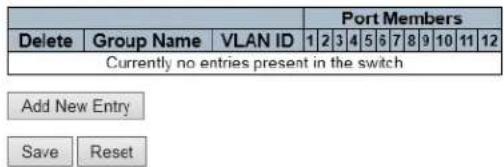
• Group Name: indicates the descriptive name of the entry. This field only allows 16 alphabetic characters (a-z; a - z) or integers (0 - 9).
• VLAN ID: Specify the VLAN.
- Click "Add New Entry" to insert a new entry into the list.
- Click the "Delete" button to delete the newly inserted entry, or select the checkbox to delete the saved entry on the next save.
IP-based VLAN configuration, if the source address is found in the IP subnet to VLAN mapping table, the unlabeled ingress frame is mapped to a specific VLAN. When IP-based VLAN classification is enabled, the source address of the unlabeled ingress framework will be checked on the IP sub-net-to-VLAN mapping table. If an entry is found for the subnet, these frames are assigned to the VLAN specified in the entry.
If there is no matching IP subnet, the untagged frame is divided into VLAN IDs (PVIDs) belonging to the receiving port.
2.21.3 IP
Subnet-based VLAN
IP Subnet-based VLAN Membership Configuration

Add New Entry
Save Reset
• IP address: Indicates the IP address of this rule.
• Mask Length: Indicates the length of the network mask.
• VLAN ID: Specify VLAN ID
- Port Members: Assign a port to the rule.
- Click the "Add New Entry" button to insert a new entry into the list.
- Click the "Delete" button to delete the newly inserted entry, or select the checkbox to delete the saved entry on the next save.
Voice VLAN
2.22 Voice VLAN

2.22.1 Configuration
Voice VLAN Configuration
| Mode | Disabled | |
| VLAN ID | 1000 | |
| Aging Time | 86400 | seconds |
| Traffic Class | 7 (High) | |
Port Configuration
| Port | Mode | Security | Discovery Protocol |
| * | <> | <> | <> |
| 1 | Disabled | Disabled | OUI |
| 2 | Disabled | Disabled | OUI |
| 3 | Disabled | Disabled | OUI |
| 4 | Disabled | Disabled | OUI |
| 5 | Disabled | Disabled | OUI |
| 6 | Disabled | Disabled | OUI |
| 7 | Disabled | Disabled | OUI |
| 8 | Disabled | Disabled | OUI |
| 9 | Disabled | Disabled | OUI |
| 10 | Disabled | Disabled | OUI |
| 11 | Disabled | Disabled | OUI |
| 12 | Disabled | Disabled | OUI |
Voice VLAN Configuration
Mode
Indicates the Voice VLAN mode operation. We must disable MSTP feature before we enable Voice VLAN. It can avoid the conflict of ingress filtering. Possible modes are:
• Enabled: Enable Voice VLAN mode operation.
• Disabled: Disable Voice VLAN mode operation.
VLAN ID
Indicates the Voice VLAN ID. It should be a unique VLAN ID in the system and cannot equal each port PVID. It is a conflict in configuration if the value equals management VID, MVR VID, PVID etc. The allowed range is 1 to 4095.
Aging Time
Indicates the Voice VLAN secure learning aging time. The allowed range is 10 to 10000000 seconds. It is used when security mode or auto-detect mode is enabled. In other cases, it will be based on hardware aging time. The actual aging time will be situated between the [age_time; 2 * age_time] interval.
Traffic Class
Indicates the Voice VLAN traffic class. All traffic on the Voice VLAN will apply to this class.
Port Configuration
Port Mode
Indicates the Voice VLAN port mode. Possible port modes are:
• Disabled: Disjoin from Voice VLAN.
• Auto: Enable auto-detect mode. It detects whether there is VoIP phone attached to the specific port and configures the Voice VLAN members automatically.
• Forced: Force join to Voice VLAN.
Port Security
Indicates the Voice VLAN port security mode. When the function is enabled, all non-telephonic MAC addresses in the Voice VLAN will be blocked for 10 seconds. Possible port modes are:
• Enabled: Enable Voice VLAN security mode operation.
• Disabled: Disable Voice VLAN security mode operation.
Port Discovery Protocol
Indicates the Voice VLAN port discovery protocol. It will only work when auto-detect mode is enabled. We should enable LLDP feature before configuring the discovery protocol to "LLDP" or "Both". Changing the discovery protocol to "OUI" or "LLDP" will restart auto-detect process. Possible discovery protocols are:
• OUI: Detect telephony device by OUI address.
• LLDP: Detect telephony device by LLDP.
• Both: Both OUI and LLDP.
2.22.2 OUI
Voice VLAN OUI Table
| Delete | Telephony OUI | Description |
| 00-01-e3 | Siemens AG phones | |
| 00-03-6b | Cisco phones | |
| 00-0f-e2 | H3C phones | |
| 00-50-b9 | Philips and NEC AG phones | |
| 00-d0-1e | Pingtel phones | |
| 00-e0-75 | Polycom phones | |
| 00-e0-bb | 3Com phones |
Add New Entry
Save
Reset
Delete
Check to delete the entry. It will be deleted during the next save.
Telephony OUI
A telephony OUI address is a globally unique identifier assigned to a vendor by IEEE. It must be 6 characters long and the input format is "xx-xx-xx" (x is a hexadecimal digit).
Description
The description of OUI address. Normally, it describes which vendor telephony device it belongs to. The allowed string length is 0 to 32. Click "Save" "Reset" button to save or cancel configuration.
Ethernet Services
2.23 Ethernet Services

2.23.1 Ports
Port Configuration
| Port | DEI Mode | Tag Mode | Address Mode |
| - | ✓ | ✓ | ✓ |
| 1 | Fixed | Outer | Source |
| 2 | Fixed | Outer | Source |
| 3 | Fixed | Outer | Source |
| 4 | Fixed | Outer | Source |
| 5 | Fixed | Outer | Source |
| 6 | Fixed | Outer | Source |
| 7 | Fixed | Outer | Source |
| 8 | Fixed | Outer | Source |
| 9 | Fixed | Outer | Source |
| 10 | Fixed | Outer | Source |
| 11 | Fixed | Outer | Source |
| 12 | Fixed | Outer | Source |
Save Reset
Port
The logical port for the settings contained in the same row.
DEI Mode
The DEI mode for an NNI port determines whether frames transmitted on the port will have the DEI field in the outer tag marked based on the color of the frame. The allowed values are:
• Colored: The DEI is 1 for yellow frames and 0 for green frames.
• Fixed: The DEI value is determined by ECE rules.
Tag Mode
The tag mode specifying whether the EVC classification must be based on the outer or inner tag. This can be used on NNI ports connected to another service provider, where an outer "tunnel" tag is added together with the inner tag identifying the EVC. The allowed values are:
• Inner: Enable inner tag in EVC classification.
• Outer: Enable outer tag in EVC classification.
Address Mode
The IP/MAC address mode specifying whether the EVC classification must be based on source (SMAC/SIP) or destination (DMAC/DIP) addresses. The allowed values are:
Source: Enable SMAC/SIP matching.
• Destination: Enable DMAC/DIP matching.
2.23.2 L2CP
L2CP Port Configuration
| DMAC | L2CP Mode |
| 01-80-C2-00-00-00 | Peer √ |
| 01-80-C2-00-00-01 | Peer √ |
| 01-80-C2-00-00-02 | Peer √ |
| 01-80-C2-00-00-03 | Peer √ |
| 01-80-C2-00-00-04 | Peer √ |
| 01-80-C2-00-00-05 | Peer √ |
| 01-80-C2-00-00-06 | Peer √ |
| 01-80-C2-00-00-07 | Peer √ |
| 01-80-C2-00-00-08 | Peer √ |
| 01-80-C2-00-00-09 | Peer √ |
| 01-80-C2-00-00-0A | Peer √ |
| 01-80-C2-00-00-0B | Peer √ |
| 01-80-C2-00-00-0C | Peer √ |
| 01-80-C2-00-00-0D | Peer √ |
| 01-80-C2-00-00-0E | Peer √ |
| 01-80-C2-00-00-0F | Peer √ |
| 01-80-C2-00-00-20 | Forward √ |
| 01-80-C2-00-00-21 | Forward √ |
| 01-80-C2-00-00-22 | Forward √ |
| 01-80-C2-00-00-23 | Forward √ |
| 01-80-C2-00-00-24 | Forward √ |
| 01-80-C2-00-00-25 | Forward √ |
| 01-80-C2-00-00-26 | Forward √ |
| 01-80-C2-00-00-27 | Forward √ |
| 01-80-C2-00-00-28 | Forward √ |
| 01-80-C2-00-00-29 | Forward √ |
| 01-80-C2-00-00-2A | Forward √ |
| 01-80-C2-00-00-2B | Forward √ |
| 01-80-C2-00-00-2C | Forward √ |
| 01-80-C2-00-00-2D | Forward √ |
| 01-80-C2-00-00-2E | Forward √ |
| 01-80-C2-00-00-2F | Forward √ |

DMAC
The destination BPDU MAC addresses (01-80-C2-00-00-0X) and GARP (01-80-C2-00-00-2X) MAC addresses for the settings contained in the same row.
L2CP Mode
The L2CP mode for the specific port. The possible values are:
• Peer: Allow to peer L2CP frames.
• Forward: Allow to forward L2CP frames
2.23.3 Bandwidth Profiles
Bandwidth Profiles Configuration


| Policer ID | State | Type | Policer Mode | Rate Type | CIR (kbps) | CBS (bytes) | EIR (kbps) | EBS (bytes) |
| 0 | 0 | |||||||
| 1 | Disabled | MEF | Coupled Aware | Data | 0 | 0 | ||
| 2 | Disabled | MEF | Aware | Data | 0 | 0 | ||
| 3 | Disabled | MEF | Aware | Data | 0 | 0 | ||
| 4 | Disabled | MEF | Aware | Data | 0 | 0 | ||
| 5 | Disabled | MEF | Aware | Data | 0 | 0 | ||
| 6 | Disabled | MEF | Aware | Data | 0 | 0 | ||
| 7 | Disabled | MEF | Aware | Data | 0 | 0 | ||
| 8 | Disabled | MEF | Aware | Data | 0 | 0 | ||
| 9 | Disabled | MEF | Aware | Data | 0 | 0 | ||
| 10 | Disabled | MEF | Aware | Data | 0 | 0 | ||
| 11 | Disabled | MEF | Aware | Data | 0 | 0 | ||
| 12 | Disabled | MEF | Aware | Data | 0 | 0 | ||
| 13 | Disabled | MEF | Aware | Data | 0 | 0 | ||
| 14 | Disabled | MEF | Aware | Data | 0 | 0 | ||
| 15 | Disabled | MEF | Aware | Data | 0 | 0 | ||
| 16 | Disabled | MEF | Aware | Data | 0 | 0 | ||
| 17 | Disabled | MEF | Aware | Data | 0 | 0 | ||
| 18 | Disabled | MEF | Aware | Data | 0 | 0 | ||
| 19 | Disabled | MEF | Aware | Data | 0 | 0 | ||
| 20 | Disabled | MEF | Aware | Data | 0 | 0 |
Save Reset
Start Policer ID
The start Policer ID for displaying the table entries. The allowed range is from 1 through 256.
Number of Entries
The number of entries per page. The allowed range is from 2 through 256.
Policer ID
The Policer ID is used to identify one of the 256 policers.
State
The administrative state of the bandwidth profile. The allowed values are:
- Enabled: The bandwidth profile enabled.
• Disabled: The bandwidth profile is disabled.
Type
The policer type of the bandwidth profile. The allowed values are:
MEF: MEF ingress bandwidth profile.
• Single: Single bucket policer.
Policer Mode
The color mode of the bandwidth profile. The allowed values are:
• Coupled: Color-aware mode with coupling enabled.
• Aware: Color-aware mode with coupling disabled.
Rate Type
The rate type of the bandwidth profile. The allowed values are:
• Data: Specify that this bandwidth profile operates on data rate.
• Line: Specify that this bandwidth profile operates on line rate.
CIR
The Committed Information Rate of the bandwidth profile. The allowed range is from 0 through 10000000 kilobit per second.
CBS
The Committed Burst Size of the bandwidth profile. The allowed range is from 0 through 100000 bytes.
EIR
The Excess Information Rate for MEF type bandwidth profile. The allowed range is from 0 through 10000000 kilobit per second.
EBS
The Excess Burst Size for MEF type bandwidth profile. The allowed range is from 0 through 100000 bytes.
2.23.4 EVCs

Click "⊕ and the EVC configuration will be showed as follow:
EVC Configuration
NNI Ports
| Type | None | √ |
| VID Mode | Normal | √ |
| VLAN ID | 1 | |
| PCP/DEI Preservation | Fixed | √ |
| PCP | 0 | √ |
| DEI | 0 | √ |
Outer Tag
| VLAN ID | 0 |

EVC ID
The EVC ID identifies the EVC. The range is from 1 through 256.
Name
The name for the EVC.
VID
The VLAN ID in the PB network. It may be inserted in a C-tag, S-tag or S-custom tag depending on the NNI port VLAN configuration. The range is from 1 through 4095.
IVID
The Internal/classified VLAN ID in the PB network. The range is from 1 through 4095.
Learning
The learning mode for the EVC controls whether source MAC addresses are learned for frames matching the EVC. Learning may be disabled if the EVC only includes two UNI/NNI ports. The possible values are:
• Enabled: Learning is enabled (MAC addresses are learned).
• Disabled: Learning is disabled (MAC addresses are not learned).
Inner Tag Type
The inner tag type is used to determine whether an inner tag is inserted in frames forwarded to NNI ports. The possible values are:
• None: An inner tag is not inserted.
• C-tag: An inner C-tag is inserted.
• S-tag: An inner S-tag is inserted.
- S-custom-tag: An inner tag is inserted and the tag type is determined by the VLAN port configuration of the NNI.
Inner VID Mode
The inner VID Mode affects the VID in the inner and outer tag. The possible values are:
• Normal: The VID of the two outer tags aren't swapped.
- Tunnel: The VID of the two outer tags are swapped, so that the VID of the outer tag is taken from the Inner Tag configuration and the VID of the inner tag is the EVC VID. In this mode, the NNI ports are normally configured to do EVC classification based on the inner tag.
Inner Tag VID
The Inner tag VLAN ID. The allowed range is from 0 through 4095.
Inner Tag PCP/DEI Preservation
The inner tag PCP and DEI preservation. The possible values are:
• Preserved: The inner tag PCP and DEI is preserved.
• Fixed: The inner tag PCP and DEI is fixed.
Inner Tag PCP
The inner tag PCP value. The allowed range is from 0 through 7.
Inner Tag DEI
The inner tag DEI value. The allowed value is 0 or 1.
Outer Tag VID
The EVC outer tag VID for UNI ports. The allowed range is from 0 through 4095.
NNI Ports
The list of Network to Network Interfaces for the EVC.
You can modify each EVC in the table using the following buttons:
e : Edits the EVC row.
: Deletes the EVC.
⊕: Adds new EVC.

Click ⬆ will show ECEs configuration page as picture below.
2.23.5 ECEs
ECE Configuration
UNI Ports
| Mode | Disabled | √ |
| PCP/DEI Preservation | Fixed | √ |
| PCP | 0 | √ |
| DEI | 0 | √ |
| Save | Reset | Cancel |
ECE ID
The ECE ID identifies the ECE. Unique ECE IDs are automatically assigned to ECEs added. The possible range is from 1 through 256.
Ingress Matching
UNI Ports
The list of User Network Interfaces for the ECE.
Tag Type
The tag type for the ECE. The possible values are:
• Any: The ECE will match both tagged and untagged frames.
• Untagged: The ECE will match untagged frames only.
• C-Tagged: The ECE will match custom tagged frames only.
• S-Tagged: The ECE will match service tagged frames only.
• Tagged: The ECE will match tagged frames only.
VID
The VLAN ID for the ECE. It only significant if tag type 'Tagged' is selected. The possible values are:
• Specific: The range is from 0 through 4095.
• Any: The ECE will match any VLAN ID.
PCP
The PCP value for the ECE. It only significant if tag type 'Tagged' is selected. The possible values are:
• Specific: The ECE will match a specific PCP in the range 0 through 7.
• Range: The ECE will match PCP values in the selected range 0-1, 2-3, 4-5, 6-7, 0-3 or 4-7.
• Any: The ECE will match any PCP value.
DEI
The DEI value for the ECE. It only significant if tag type 'Tagged' is selected. The possible values is: 0, 1 or Any.
Frame Type
The frame type for the ECE. The possible values are:
• Any: The ECE will match any frame type.
• IPv4: The ECE will match IPv4 frames only.
• IPv6: The ECE will match IPv6 frames only.
Actions
Direction
The EVCs and ECEs are used to setup flows in one or both directions as determined by the ECE Direction parameter. If the ECE is bidirectional, the ingress rules of the NNI ports will be setup to match the traffic being forwarded to NNI ports. Possible values are:
• Both: Bidirectional.
• UNI-to-NNI: Unidirectional from UNI to NNI.
• NNI-to-UNI: Unidirectional from NNI to UNI.
EVC ID
The EVC ID for the ECE. The ECE is only active when mapping to an existing EVC. Possible values are:
• Specific: The range is from 1 through 256.
• None: The ECE does not map to an EVC.
Tag Pop Count
The ingress tag pop count for the ECE. The possible range is from 0 through 2.
Policy ID
The ACL Policy ID for the ECE. The range is from 0 through 255.
Class
The traffic class for the ECE. The range is from 0 through 7.
Egress Outer Tag
Outer Tag Mode
The outer tag for nni-to-uni direction for the ECE. The possible values are:
- Enable: Enable outer tag for nni-to-uni direction for the ECE.
• Disable: Disable outer tag for nni-to-uni direction for the ECE.
Outer Tag PCP/DEI Preservation
The outer tag PCP and DEI preservation for the ECE. The possible values are:
• Preserved: The outer tag PCP and DEI are preserved.
• Disable: The outer tag PCP and DEI are fixed.
Outer Tag PCP
The outer tag PCP value for the ECE. The possible range is from 0 through 7.
Outer Tag DEI
The outer tag DEI value for the ECE. The possible value is 0 or 1.
Conflict
Indicates the hardware status of the specific ECE. The specific ECE is not applied to the hardware due to hardware limitations.
You can modify each ECE (EVC Control Entry) in the table using the following buttons:
⊕: Inserts a new ECE before the current row.
e: Edits the ECE row.
: Moves the ECE up the list.
↓: Moves the ECE down the list.
✗: Deletes the ECE.
⊕: The lowest plus sign adds a new entry at the bottom of the ECE listings.
QoS
2.24 QoS
Network traffic is always unpredictable. The only basic guarantee that can be provided is the best traffic delivery. QoS has been applied throughout the network to overcome this challenge. This ensures that network traffic is sorted according to specified criteria and is prioritized. QoS allows you to assign different levels of web services for different types of communication, such as multimedia, video, protocol-specific, time critical, and file backup communications. To set the priority of a packet in this switch, go to the "Port Classification" page.
QoS menu contains the submenus below.

2.24.1 Port Classification
QoS Ingress Port Classification
| Port | CoS | DPL | PCP | DEI | Tag Class. | DSCP Based | Address Mode |
| * | <> √ | <> √ | <> √ | <> √ | ☐ | <> √ | |
| 1 | 0 √ | 0 √ | 0 √ | 0 √ | Disabled | ☐ | Source √ |
| 2 | 0 √ | 0 √ | 0 √ | 0 √ | Disabled | ☐ | Source √ |
| 3 | 0 √ | 0 √ | 0 √ | 0 √ | Disabled | ☐ | Source √ |
| 4 | 0 √ | 0 √ | 0 √ | 0 √ | Disabled | ☐ | Source √ |
| 5 | 0 √ | 0 √ | 0 √ | 0 √ | Disabled | ☐ | Source √ |
| 6 | 0 √ | 0 √ | 0 √ | 0 √ | Disabled | ☐ | Source √ |
| 7 | 0 √ | 0 √ | 0 √ | 0 √ | Disabled | ☐ | Source √ |
| 8 | 0 √ | 0 √ | 0 √ | 0 √ | Disabled | ☐ | Source √ |
| 9 | 0 √ | 0 √ | 0 √ | 0 √ | Disabled | ☐ | Source √ |
| 10 | 0 √ | 0 √ | 0 √ | 0 √ | Disabled | ☐ | Source √ |
| 11 | 0 √ | 0 √ | 0 √ | 0 √ | Disabled | ☐ | Source √ |
| 12 | 0 √ | 0 √ | 0 √ | 0 √ | Disabled | ☐ | Source √ |
Save Reset
Port
The port number for which the configuration below applies.
CoS
Controls the default class of service.
All frames are classified to a CoS. There is a one-to-one mapping between CoS, queue and priority. A CoS of 0 (zero) has the lowest priority.
If the port is VLAN aware, the frame is tagged and Tag Class. is enabled, then the frame is classified to a CoS that is mapped from the PCP and DEI value in the tag. Otherwise, the frame is classified to the default CoS.
The classified CoS can be overruled by a QCL entry.
Note: If the default CoS has been dynamically changed, then the actual default CoS is shown in parentheses after the configured default CoS.
DPL
Controls the default drop precedence level.
All frames are classified to a drop precedence level.
If the port is VLAN aware, the frame is tagged and Tag Class. is enabled, then the frame is classified to a DPL that is mapped from the PCP and DEI value in the tag. Otherwise, the frame is classified to the default DPL.
The classified DPL can be overruled by a QCL entry.
PCP
Controls the default PCP value.
All frames are classified to a PCP value.
If the port is VLAN aware and the frame is tagged, then the frame is classified to the PCP value in the tag. Otherwise, the frame is classified to the default PCP value.
DEI
Controls the default DEI value.
All frames are classified to a DEI value.
If the port is VLAN aware and the frame is tagged, then the frame is classified to the DEI value in the tag. Otherwise, the frame is classified to the default DEI value.
Tag Class.
Shows the classification mode for tagged frames on this port.
• Disabled: Use default CoS and DPL for tagged frames.
• Enabled: Use mapped versions of PCP and DEI for tagged frames.
Click on the mode in order to configure the mode and/or mapping.
Note: This setting has no effect if the port is VLAN unaware. Tagged frames received on VLAN unaware ports are always classified to the default CoS and DPL.
DSCP Based
Click to Enable DSCP Based QoS Ingress Port Classification.
Address Mode
The IP/MAC address mode specifying whether the QCL classification must be based on source (SMAC/SIP) or destination (DMAC/DIP) addresses on this port. The allowed values are:
• Source: Enable SMAC/SIP matching.
• Destination: Enable DMAC/DIP matching.
2.24.2 Port Policing
QoS Ingress Port Policers
| Port | Enable | Rate | Unit | Flow Control |
| * | □ | 500 | <> √ | □ |
| 1 | □ | 500 | kbps √ | □ |
| 2 | □ | 500 | kbps √ | □ |
| 3 | □ | 500 | kbps √ | □ |
| 4 | □ | 500 | kbps √ | □ |
| 5 | □ | 500 | kbps √ | □ |
| 6 | □ | 500 | kbps √ | □ |
| 7 | □ | 500 | kbps √ | □ |
| 8 | □ | 500 | kbps √ | □ |
| 9 | □ | 500 | kbps √ | □ |
| 10 | □ | 500 | kbps √ | □ |
| 11 | □ | 500 | kbps √ | □ |
| 12 | □ | 500 | kbps √ | □ |
Save Reset
This page allows you to configure the Policer settings for all switch ports.
Port
The port number for which the configuration below applies.
Enable
Enable or disable the port policer for this switch port.
Rate
Controls the rate for the port policer. This value is restricted to 100-3276700 when "Unit" is kbps or fps, and 1-3276 when "Unit" is Mbps or kfps. The rate is internally rounded up to the nearest value supported by the port policer.
Unit
Controls the unit of measure for the port policer rate as kbps, Mbps, fps or kfps.
Flow Control
If flow control is enabled and the port is in flow control mode, then pause frames are sent instead of discarding frames
2.24.3 Queue Policing
QoS Ingress Queue Policers
• Port: Device port number. "*" setting applies to all ports.
- Queue 0-7 Enable: Select the appropriate checkbox to enable queue management on the switch port.
When enabled, the following image will be displayed:
QoS Ingress Queue Policers
| Port | Queue 0 | Queue 1 | Queue 2 | Queue 3 | Queue 4 | Queue 5 | Queue 6 | Queue 7 | ||
| E | Rate | Unit | Enable | Enable | Enable | Enable | Enable | Enable | Enable | |
| * | ☑ | 500 | <> √ | ☐ | ☐ | ☐ | ☐ | ☐ | ☐ | ☐ |
| 1 | ☑ | 500 | kbps √ | ☐ | ☐ | ☐ | ☐ | ☐ | ☐ | ☐ |
| 2 | ☑ | 500 | kbps √ | ☐ | ☐ | ☐ | ☐ | ☐ | ☐ | ☐ |
| 3 | ☑ | 500 | kbps √ | ☐ | ☐ | ☐ | ☐ | ☐ | ☐ | ☐ |
| 4 | ☑ | 500 | kbps √ | ☐ | ☐ | ☐ | ☐ | ☐ | ☐ | ☐ |
| 5 | ☑ | 500 | kbps √ | ☐ | ☐ | ☐ | ☐ | ☐ | ☐ | ☐ |
| 6 | ☑ | 500 | kbps √ | ☐ | ☐ | ☐ | ☐ | ☐ | ☐ | ☐ |
| 7 | ☑ | 500 | kbps √ | ☐ | ☐ | ☐ | ☐ | ☐ | ☐ | ☐ |
| 8 | ☑ | 500 | kbps √ | ☐ | ☐ | ☐ | ☐ | ☐ | ☐ | ☐ |
| 9 | ☑ | 500 | kbps √ | ☐ | ☐ | ☐ | ☐ | ☐ | ☐ | ☐ |
| 10 | ☑ | 500 | kbps √ | ☐ | ☐ | ☐ | ☐ | ☐ | ☐ | ☐ |
| 11 | ☑ | 500 | kbps √ | ☐ | ☐ | ☐ | ☐ | ☐ | ☐ | ☐ |
| 12 | ☑ | 500 | kbps √ | ☐ | ☐ | ☐ | ☐ | ☐ | ☐ | ☐ |
Save Reset
• Rate: Means the rate of the ingress queue.
• By default, 500 kbps is used. The range allowed by kbps is 100 to 1000000. The allowed range is 1 to 3300 Mbps.
• Unit: Select measure unit for the ingress queue.
• Save: Save the currently running configuration to memory.
• Reset: Clear all selected settings
2.24.4 Port Scheduler
QoS Egress Port Schedulers
| Port | Mode | Weight | |||||
| Q0 | Q1 | Q2 | Q3 | Q4 | Q5 | ||
| 1 | Strict Priority | - | - | - | - | - | - |
| 2 | Strict Priority | - | - | - | - | - | - |
| 3 | Strict Priority | - | - | - | - | - | - |
| 4 | Strict Priority | - | - | - | - | - | - |
| 5 | Strict Priority | - | - | - | - | - | - |
| 6 | Strict Priority | - | - | - | - | - | - |
| 7 | Strict Priority | - | - | - | - | - | - |
| 8 | Strict Priority | - | - | - | - | - | - |
| 9 | Strict Priority | - | - | - | - | - | - |
| 10 | Strict Priority | - | - | - | - | - | - |
| 11 | Strict Priority | - | - | - | - | - | - |
| 12 | Strict Priority | - | - | - | - | - | - |
QoS Egress Port Scheduler and Shapers Port 1

flowchart
graph TD
    A["Queue Shaper"] --> B["STRICT"]
    B --> C["Port Shaper"]
    subgraph Queue Shaper
        D["Enable"] --> E["Rate"] --> F["Unit"] --> G["Excess"]
        H["u1-8"] --> I["500 kbps"] --> J["✓"]
        K["u2-8"] --> L["500 kbps"] --> M["✓"]
        N["u3-8"] --> O["500 kbps"] --> P["✓"]
        Q["u4-8"] --> R["500 kbps"] --> S["✓"]
        T["u5-8"] --> U["500 kbps"] --> V["✓"]
        W["u6-8"] --> X["500 kbps"] --> Y["✓"]
        Z["u7-8"] --> AA["500 kbps"] --> AB["✓"]
        AC["u8-8"] --> AD["500 kbps"] --> AE["✓"]
        AF["Save"] --> AG["Reset"] --> AH["Back"]
    end
- Port: Device port number. Click the port number to enter into the port scheduler to set detail settings. Click the corresponding port number such as "1", it will appear the dialog box above:
• Mode: The selected display scheduler mode.
• Weight: Displays the weight by percentage that assigned to Q0-Q5. This page allows you to set up a scheduler and shader for a specific port.
• Scheduler Mode: This device provides two modes to dispose queues.
• Strict Priority: Before the lower priority priority queue it will delivery the priority queues first.
• 6 Queues Weighted: To assigns DWRR queue of scheduling weight for each quenue - (Option: strict, weighted; The default is strict) DWRR serves the queue in a similar way to WRR, but only if the queue's deficit counter is less than the packet size to be transmitted, the next queue will be serviced.
Queue's shaper
Scheduler Mode
Controls how many of the queues are scheduled as strict and how many are scheduled as weighted on this switch port.
Queue Shaper Enable
Controls whether the queue shaper is enabled for this queue on this switch port.
Queue Shaper Rate
Controls the rate for the queue shaper. This value is restricted to 100-3281943 when "Unit" is kbps, and 1-3281 when "Unit" is Mbps. The rate is internally rounded up to the nearest value supported by the queue shaper.
Queue Shaper Unit
Controls the unit of measure for the queue shaper rate as kbps or Mbps.
Queue Shaper Excess
Controls whether the queue is allowed to use excess bandwidth.
Queue Scheduler Weight
Controls the weight for this queue. This value is restricted to 1-100. This parameter is only shown if "Scheduler Mode" is set to "Weighted".
Queue Scheduler Percent
Shows the weight in percent for this queue. This parameter is only shown if "Scheduler Mode" is set to "Weighted".
Port Shaper Enable
Controls whether the port shaper is enabled for this switch port.
Port Shaper Rate
Controls the rate for the port shaper. This value is restricted to 100-3281943 when "Unit" is kbps, and 1-3281 when "Unit" is Mbps. The rate is internally rounded up to the nearest value supported by the port shaper.
Port Shaper Unit
Controls the unit of measure for the port shaper rate as kbps or Mbps.
2.24.5 Port Shaping
QoS Egress Port Shapers
| Port | Shapers | ||||||||
| Q0 | Q1 | Q2 | Q3 | Q4 | Q5 | Q6 | Q7 | Port | |
| 12 | - | - | - | - | - | - | - | - | - |
| 34 | - | - | - | - | - | - | - | - | - |
| 45 | - | - | - | - | - | - | - | - | - |
| 67 | - | - | - | - | - | - | - | - | - |
| 89 | - | - | - | - | - | - | - | - | - |
| 1011 | - | - | - | - | - | - | - | - | - |
| 1212 | - | - | - | - | - | - | - | - | - |
• It will show the rate of each port queue and port shapers.
- Click port number to modity or reset the rate of queue shapter and port shaper.
- Please refer to "Port scheduler" for a detailed description of each configuration option.
2.24.6 Port Tag Remarking
QoS Egress Port Tag Remarking
| Port | Mode |
| 1 | Classified |
| 2 | Classified |
| 3 | Classified |
| 4 | Classified |
| 5 | Classified |
| 6 | Classified |
| 7 | Classified |
| 8 | Classified |
| 9 | Classified |
| 10 | Classified |
| 11 | Classified |
| 12 | Classified |
QoS Egress Port Tag Remarking Port 1
| Tag Remarking Mode | Classified |
| Default | |
| Mapped |
• Tag Selection mode: Select the appropriate comment mode to use for this port.
• Classification: Use the pcp/dei value of the classification.
• Default: Use the default PCP/dei value (default PCP: 0; default some: 0).
• Mapping: Map the classified QoS class values and DP levels to pc/dei values.
• QoS class/DP level: Displays mapping parameters (deletion priorities) for QoS class values and DP levels.
- PCP: Match the output frame with the specified priority code point value (or user priority). (Range: 0 \~ 7; default: 0)
• Instead: Matched by the decline eligibility indicator. (Range: 0 \~ 1; default: 0)
2.24.7 Port DSCP
QoS Port DSCP Configuration
| Port | Ingress | Egress | ||
| Translate | Classify | Rewrite | ||
| * | □ | <> √ | <> | √ |
| 1 | □ | Disable √ | Disable | √ |
| 2 | □ | Disable √ | Disable | √ |
| 3 | □ | Disable √ | Disable | √ |
| 4 | □ | Disable √ | Disable | √ |
| 5 | □ | Disable √ | Disable | √ |
| 6 | □ | Disable √ | Disable | √ |
| 7 | □ | Disable √ | Disable | √ |
| 8 | □ | Disable √ | Disable | √ |
| 9 | □ | Disable √ | Disable | √ |
| 10 | □ | Disable √ | Disable | √ |
| 11 | □ | Disable √ | Disable | √ |
| 12 | □ | Disable √ | Disable | √ |
| Save | Reset |
Port
The Port column shows the list of ports for which you can configure dscp ingress and egress settings. Ingress
In Ingress settings you can change ingress translation and classification settings for individual ports. There are two configuration parameters available in Ingress:
-
Translate
-
Classify
1. Translate
To Enable the Ingress Translation click the checkbox.
2. Classify
Classification for a port have 4 different values.
• Disable: No Ingress DSCP Classification.
• DSCP=0: Classify if incoming (or translated if enabled) DSCP is 0.\
• Selected: Classify only selected DSCP for which classification is enabled as specified in DSCP Translation window for the specific DSCP.
• All: Classify all DSCP.
Egress
Port Egress Rewriting can be one of –
- Disable: No Egress rewrite.
- Enable: Rewrite enabled without remapping.
- Remap DP Unaware: DSCP from analyzer is remapped and frame is remarked with remapped DSCP value. The remapped DSCP value is always taken from the 'DSCP Translation->Egress Remap DP0' table.
- Remap DP Aware: DSCP from analyzer is remapped and frame is remarked with remapped DSCP value. Depending on the DP level of the frame, the remapped DSCP value is either taken from the 'DSCP Translation->Egress Remap DP0' table or from the 'DSCP Translation->Egress Remap DP1' table.
2.24.8 DSCP-based QoS
DSCF-Based QoS Ingress Classification
Port: Device port number. "*" setting applies to all ports
DSCP
Maximum number of supported DSCP values are 64.
Trust
Controls whether a specific DSCP value is trusted. Only frames with trusted DSCP values are mapped to a specific QoS class and Drop Precedence Level. Frames with untrusted DSCP values are treated as a non-IP frame.
QoS Class
QoS class value can be any of (0-7)
DPL
Drop Precedence Level (0-1)
2.24.9 DSCP Translation
DSCP Translation
| DSCP | Ingress | Express | ||||
| Translate | Classify | Remep DP0 | Remep DP1 | |||
| * | <5 | √ | □ | <5 | √ | <5 |
| 0 (BE) | 0 (BE) | √ | □ | 0 (BE) | √ | 0 (BE) |
| 1 | 1 | √ | □ | 1 | √ | 1 |
| 2 | 2 | √ | □ | 2 | √ | 2 |
| 3 | 3 | √ | □ | 3 | √ | 3 |
| 4 | 4 | √ | □ | 4 | √ | 4 |
| 5 | 5 | √ | □ | 5 | √ | 5 |
| 6 | 6 | √ | □ | 6 | √ | 6 |
| 7 | 7 | √ | □ | 7 | √ | 7 |
| 8 (CS1) | 8 (CS1) | √ | □ | 8 (CS1) | √ | 8 (CS1) |
| 9 | 9 | √ | □ | 9 | √ | 9 |
| 10(AF11) | 10 (AF11) | √ | □ | 10 (AF11) | √ | 10 (AF11) |
| 11 | 11 | √ | □ | 11 | √ | 11 |
| 12(AF12) | 12 (AF12) | √ | □ | 12 (AF12) | √ | 12 (AF12) |
| 13 | 13 | √ | □ | 13 | √ | 13 |
| 14(AF13) | 14 (AF13) | √ | □ | 14 (AF13) | √ | 14 (AF13) |
| 15 | 15 | √ | □ | 15 | √ | 15 |
| 16(CS2) | 16 (CS2) | √ | □ | 16 (CS2) | √ | 16 (CS2) |
| 17 | 17 | √ | □ | 17 | √ | 17 |
| 18(AF21) | 18 (AF21) | √ | □ | 18 (AF21) | √ | 18 (AF21) |
| 19 | 19 | √ | □ | 19 | √ | 19 |
| 20(AF22) | 20 (AF22) | √ | □ | 20 (AF22) | √ | 20 (AF22) |
| 21 | 21 | √ | □ | 21 | √ | 21 |
| 22(AF23) | 22 (AF23) | √ | □ | 22 (AF23) | √ | 22 (AF23) |
| 23 | 23 | √ | □ | 23 | √ | 23 |
| 24(CR3) | 24 (CR3) | √ | □ | 24 (CR3) | √ | 24 (CR3) |
| 25 | 25 | √ | □ | 25 | √ | 25 |
| 26(AF24) | 26 (AF24) | √ | □ | 26 (AF24) | √ | 26 (AF24) |
DSCP
Maximum number of supported DSCP values are 64 and valid DSCP value ranges from 0 to 63.
Ingress
Ingress side DSCP can be first translated to new DSCP before using the DSCP for QoS class and DPL map.
There are two configuration parameters for DSCP Translation -
-
Translate
-
Classify
-
Translate
DSCP at Ingress side can be translated to any of (0-63) DSCP values.
- Classify
Click to enable Classification at Ingress side.
Egress
There are the following configurable parameters for Egress side –
-
Remap DP0 Controls the remapping for frames with DP level 0.
-
Remap DP1 Controls the remapping for frames with DP level 1.
-
Remap DPO
Select the DSCP value from select menu to which you want to remap. DSCP value ranges form 0 to 63.
- Remap DP1
Select the DSCP value from select menu to which you want to remap. DSCP value ranges form 0 to 63.
2.24.10 DSCP
Classification
DSCP Classification
| QuS Class | DSCP DP0 | DSCP DP1 | ||
| * | ◇ | ▽ | ◇ | ▽ |
| 0 | 0(BE) | ▽ | 0(BE) | ▽ |
| 1 | 0(BE) | ▽ | 0(BE) | ▽ |
| 2 | 0(BE) | ▽ | 0(BE) | ▽ |
| 3 | 0(BE) | ▽ | 0(BE) | ▽ |
| 4 | 0(BE) | ▽ | 0(BE) | ▽ |
| 5 | 0(BE) | ▽ | 0(BE) | ▽ |
| 6 | 0(BE) | ▽ | 0(BE) | ▽ |
| 7 | 0(BE) | ▽ | 0(BE) | ▽ |
QoS Class
Actual QoS class.
DSCP DPO
Select the classified DSCP value (0-63) for Drop Precedence Level 0.
DSCP DP1
Select the classified DSCP value (0-63) for Drop Precedence Level 1.
The QoS Control List is used to establish a policy for processing packets based on frame type, MAC address, Vader, PCP, and DEI values.
Once the QCE is mapped to a port, traffic matching the first entry in the QoS Control List is assigned to the QoS class, drop priority, and the DSCP value defined by the entry.
Traffic that doesn't match any QCEs is divided into the default QoS level of the port.
2.24.11 QoS Control
List
QoS Control List Configuration
| QCE | Port | DMAC | SMAC | Tag Type | VID | PCP | DEI | Frame Type | Action | |||||
| CoS | DPL | DSCP | PCP | DEI | Policy | |||||||||
This page can only show in rule created in Qos Control List. The largest quantity for QCL is 256 in this device.
Click to add a new QCL in list. Display QoS Control entry index.
QCE Configuration
| Port Members | ||||||||||
| 1 | 2 | 3 | 4 | 5 | 6 | 7 | 8 | 9 | 10 | 11 |
| ☑ | ☑ | ☑ | ☑ | ☑ | ☑ | ☑ | ☑ | ☑ | ☑ | ☑ |
Key Parameters
| DMAC | Any |
| SMAC | Any |
| Tag | Any |
| VID | Any |
| PCP | Any |
| DEI | Any |
| Frame Type | Any |
Action Parameters
| CoS | 0 |
| DPL | Default |
| DSCP | Default |
| PCP | Default |
| DEI | Default |
| Policy |
Save Reset Cancel
QCE
Indicates the QCE id.
Port
Indicates the list of ports configured with the QCE or 'Any'.
DMAC
Indicates the destination MAC address. Possible values are:
• Any: Match any DMAC.
• Unicast: Match unicast DMAC.
• Multicast: Match multicast DMAC.
• Broadcast: Match broadcast DMAC.
The default value is 'Any'.
SMAC
Match specific source MAC address or 'Any'.
If a port is configured to match on destination addresses, this field indicates the DMAC.
Tag Type
Indicates tag type. Possible values are:
• Any: Match tagged and untagged frames.
• Untagged: Match untagged frames.
• Tagged: Match tagged frames.
The default value is 'Any'.
VID
Indicates (VLAN ID), either a specific VID or range of VIDs. VID can be in the range 1-4095 or 'Any'
PCP
Priority Code Point: Valid values of PCP are specific(0, 1, 2, 3, 4, 5, 6, 7) or range(0-1, 2-3, 4-5, 6-7, 0-3, 4-7) or 'Any'.
DEI
Drop Eligible Indicator: Valid value of DEI are 0, 1 or 'Any'.
Frame Type : Frame type can be any value below : Any\Ethertype\LLC\SNAP\IPv4\IPv6 Any: Allows all kinds of frame
ETherType: Effective ether type can be x600-0xffff exclue 0 x800(IPv4) and 0 x86dd(IPv6) or "Any". LLC: DSAP address: effective DSAP (Destination service access point) can be 0 x00 0 xff or "Any"
SSAP address: Effective SSAP (Source service access point) can be 0 x00 0 xff or "Any" Control: Effective control area can be 0 x00 0 xff or "Any".
SANP: Effective PID (a.k.a ether type) can be 0x0000-0xFFFFFor"Any".
IPv4: protocol: IP protocol number (0-255," TCP" or "UDP") or "Any".
Source IP: The specific source IP address is in the value/mask format or 'Any'. IP and mask are in format x. Xy, z, and w with w between 0 and 255 are decimals.
When converting a mask to a 32-bit binary string and reading from left to right, all bits after the first zero must be zero. If a port is configured matching dmac/dip, this field is Destination IP address. IP fragment: IPv4 Frame fragmentation option: "Yes", "No" or "Any". DSCP: It can be specific value, range of balue or "Any". DSCP value in the rage of 0-63, include: cs1-cs7, EF or AF11-AF43。
Sport: source tcp/udp port: (0-65538) or "Any", Specific or port range applies to IP protocol udp/tcp. Dport: target tcp udp port: (0-65535) or "Any", Specific or port range applies to IP protocol udp/tcp. IPv6:protocol: IP protocol number (0-255,"TCP" or "UDP") or "Any".
Source IP: IPv6 of 32LS is in the value/mask format or 'Any'. If a port is configured matching dmac/dip, This field is Destination IP address.
DSCP: It can be specific value, range of balue or "Any". DSCP value in the rage of 0-63, include: cs1-cs7, EF or AF11-AF43.
Sport: source tcp/udp port: (0-65538) or "Any", Specific or port range applies to IP protocol udp/tcp. Dport: target tcp udp port: (0-65535) or "Any", Specific or port range applies to IP protocol udp/tcp. Action Parameters
CoS: Service type: (0-7) or "default"
DPL: Delete priority: (0-1) or "default value"
DSCP: (0-63,is,cs1-cs7, EF or AF11-AF43) or "default"
PCP : Pneumocystis pneumonia :(0-7) or "default". Notice: PCP and DEI can't set separately.
Notice: "default" means Default classification value will not be modifying by QCE
Storm control prevents network degradation or complete shutdown by setting thresholds for traffic such as broadcast, unicast, and multicast.
When a device on the network fails or the application is poorly designed or configured incorrectly, a storm can occur and can degrade network performance and can even lead to complete outages. By setting thresholds for the specified traffic in the device, you can protect your network from storms. Any specified packet that exceeds the specified threshold will be deleted
2.24.12 Storm Policing
Global Storm Policer Configuration
| Frame Type | Enable | Rate | Unit |
| Unicast | 1 | fps | |
| Multicast | 1 | fps | |
| Broadcast | 1 | fps |
Enable
Enable or disable the global storm policer for the given frame type.
Rate
Controls the rate for the global storm policer. This value is restricted to 1-1024000 when "Unit" is fps, and 1-1024 when "Unit" is kfps. The rate is internally rounded up to the nearest value supported by the global storm policer.
Unit
Controls the unit of measure for the global storm policer rate as fps or kfps.
Mirroring
2.25 Mirroring
To facilitate management of the switch, you can configure port mirroring and use one port of the switch to observe traffic flowing through a group of ports.


Mirroring&Remote Mirroring Configuration
- Mode: Disabled\Enabled
- Type:
Mirror
The switch is running on mirror mode.
The source port(s) and destination port are located on this switch.
Source
The switch is a source node for monitor flow.
The source port(s), reflector port and intermediate port(s) are located on this switch.
Intermediate
The switch is a forwarding node for monitor flow and the switch is an option node.
The object is to forward traffic from source switch to destination switch.
The intermediate ports are located on this switch.
Destination
The switch is an end node for monitor flow.
The destination port(s) and intermediate port(s) are located on this switch.
VLAN ID: The VLAN ID points out where the monitor packet will copy to. The default VLAN ID is 200.
Reflector Port:
The reflector port is a method to redirect the traffic to Remote Mirroring VLAN. Any device connected to a port set as a reflector port loses connectivity until the Remote Mirroring is disabled.
In the stacking mode, you need to select switch ID to select the correct device.
If you shut down a port, it cannot be a candidate for reflector port.
If you shut down the port which is a reflector port, the remote mirror function cannot work.
Note1: The reflector port needs to select only on Source switch type.
Note2: The reflector port needs to disable MAC Table learning and STP.
Note3: The reflector port only supports on pure copper ports.
Source VLAN(s) Configuration:
The switch can support VLAN-based Mirroring. If you want to monitor some VLANs on the switch, you can set the selected VLANs on this field.
Note: The Mirroring session shall have either ports or VLANs as sources, but not both.
Remote Mirroring Port Configuration:
The following table is used for port role selecting.
Port
The logical port for the settings contained in the same row.
Source
Select mirror mode.
• Disabled Neither frames transmitted nor frames received are mirrored.
• Both Frames received and frames transmitted are mirrored on the Intermediate/Destination port.
- Rx only Frames received on this port are mirrored on the Intermediate/Destination port. Frames transmitted are not mirrored.
• Tx only Frames transmitted on this port are mirrored on the Intermediate/Destination port. Frames received are not mirrored.
Intermediate
Select intermediate port.
This checkbox is designed for Remote Mirroring.
The intermediate port is a switched port to connect to other switch.
Note: The intermediate port needs to disable MAC Table learning.
Destination
Select destination port.
This checkbox is designed for mirror or Remote Mirroring.
The destination port is a switched port that you receive a copy of traffic from the source port.
Note1: On mirror mode, the device only supports one destination port.
Note2: The destination port needs to disable MAC Table learning.
UPnP
2.26 UPnP

2.26.1 UPnP Configuration
UPnP Configuration

Mode
Indicates the UPnP operation mode. Possible modes are:
- Enabled: Enable UPnP mode operation.
• Disabled: Disable UPnP mode operation.
When the mode is enabled, two ACEs are added automatically to trap UPNP related packets to CPU. The ACEs are automatically removed when the mode is disabled.
TTL
The TTL value is used by UPnP to send SSDP advertisement messages. Valid values are in the range 1 to 255.
Advertising Duration
The duration, carried in SSDP packets, is used to inform a control point or control points how often it or they should receive an SSDP advertisement message from this switch. If a control point does not receive any message within the duration, it will think that the switch no longer exists. Due to the unreliable nature of UDP, in the standard it is recommended that such refreshing of advertisements to be done at less than one-half of the advertising duration. In the implementation, the switch sends SSDP messages periodically at the interval one-half of the advertising duration minus 30 seconds. Valid values are in the range 100 to 86400.
GRPRP (GARP VLAN Registration Protocol) is a specific application based on the GARP (Generic Attribute Registration Protocol) protocol.
It uses the working mechanism of the GARP protocol to maintain VLAN information in the switch. All switches that support GVRP can receive VLAN registration information from other switches and update dynamically.
Local VLAN registration information includes the current VLAN membership. And these VLAN members can be reaching by which port. At the same time, all the switches that support the GVRP feature can transmit the local VLAN registration information (including the dynamic VLAN information and the statically configured VLAN information) propagates to other switches to achieve the same VLAN information of all GVRP-enabled devices in the same switching network.
Please enable GVRP globally before enabling GVRP, Otherwise, the GVRP function doesn't work. GVRP can be configured only on the trunk port. Otherwise, the GVRP function will not work too. Port GVRP is closed in the default status.
GVRP
2.27 GVRP

2.27.1 Global Config
GVRP Configuration
| Parameter | Value |
| Join-time: | 20 |
| Leave-time: | 60 |
| LeaveAll-time: | 1000 |
| Max VLANs: | 20 |
Save
The default status is closed, Pleas mark √ in "Enabled GVRP" if you need turn on it.
2.27.2 Port Config
GVRP Port Configuration
| Port | Mode | |
| * | <> | ✓ |
| 1 | Disabled | ✓ |
| 2 | Disabled | ✓ |
| 3 | Disabled | ✓ |
| 4 | Disabled | ✓ |
| 5 | Disabled | ✓ |
| 6 | Disabled | ✓ |
| 7 | Disabled | ✓ |
| 8 | Disabled | ✓ |
| 9 | Disabled | ✓ |
| 10 | Disabled | ✓ |
| 11 | Disabled | ✓ |
| 12 | Disabled | ✓ |
Save
Reset
The default status of port is closed. Turn on by drop-down menu "GVRP enabled" option. Click "SAVE" to save settings.
2.28 sFlow

sFlow Configuration
Agent Configuration

Receiver Configuration
| Owner | Release | |
| IP Address/Hostname | 0.0.0 | seconds bytes |
| UDP Port | 6343 | |
| Timeout | 0 | |
| Max. Datagram Size | 1400 |
Port Configuration
| Port | Flow Sampler | Counter Poller | |||
| Enabled | Sampling Rate | Max. Header | Enabled | Interval | |
| * | 0 | 128 | 0 | ||
| 1 | 0 | 128 | 0 | ||
| 2 | 0 | 128 | 0 | ||
| 3 | 0 | 128 | 0 | ||
| 4 | 0 | 128 | 0 | ||
| 5 | 0 | 128 | 0 | ||
| 6 | 0 | 128 | 0 | ||
| 7 | 0 | 128 | 0 | ||
| 8 | 0 | 128 | 0 | ||
| 9 | 0 | 128 | 0 | ||
| 10 | 0 | 128 | 0 | ||
| 11 | 0 | 128 | 0 | ||
| 12 | 0 | 128 | 0 | ||

sFlow is a network monitoring technology co-developed by InMon, HP and FoundryNetworks in 2001. It uses data flow random sampling technology to provide complete Layer 2 to Layer 4, and even network-wide traffic information, which can adapt to traffic analysis in environments with large network traffic (eg, greater than 10 Gbit/s), allowing users to analyze the performance, trends, and problems of network transport flow detailedly in real time.
UDLD (UniDirectional Link Detection): A Cisco proprietary Layer 2 protocol for monitoring the physical configuration of Ethernet links connected by fiber or twisted pair.
UDLD can detect this situation when a unidirectional link occurs (can only be transmitted in one direction, for example, I can send the data to you, you can also receive it, but I can't receive the data you sent to me.)
Close the corresponding interface and send a warning message. A unidirectional link can cause a lot of problems, especially spanning trees, which can cause loopbacks. Note: UDLD requires both devices at both ends of the link to support normal operation.
Port: Device port number. "*" configuration applies to all ports.
2.28.1 UDLD
UDLD Mode
Configures the UDLD mode on a port. Valid values are Disable, Normal and Aggressive. Default mode is Disable.
- Disable: In disabled mode, UDLD functionality doesn't exists on port.
• Normal :In normal mode, if the link state of the port was determined to be unidirectional, it will not affect the port state.
• Aggressive: In aggressive mode, unidirectional detected ports will get shutdown. To bring back the ports up, need to disable UDLD on that port.
Message Interval
Configures the period of time between UDLD probe messages on ports that are in the advertisement phase and are determined to be bidirectional. The range is from 7 to 90 seconds (Default value is 7 seconds) (Currently default time interval is supported, due to lack of detailed information in RFC 5171).
Chapter 3: Monitor
3. Monitor
The monitor section provides visual confirmation and real time status of programmed functions performed in the configuration section. Monitor page display can be control by any of the following methods depending on the individual page:
Auto-refresh □ Refresh Clear
Select Auto Refresh and the page will automatically refresh at a preselect time. Without it select the log or function can be cleared manually
Auto-refresh □ Refresh Clear |<< << >> >>|
In some cases there are individual line controls. The two outer arrows will display the first and last displays, the middle two will increment the ports by one.
System
3.1 System Information
System information displays the programmed system information, hardware and software
System Information
| System | |
| Contact | |
| Name | |
| Location | |
| Hardware | |
| MAC Address | 08-ed-02-59-20-41 |
| Chip ID | ABC-888 |
| Software | |
| Software Version | CE |
| Software Date | 09-2019 |
| Acknowledgments | Details |
3.1.2 CPU Load
The CPU load shows its performance. Loads greater than 75% can affect the operation.
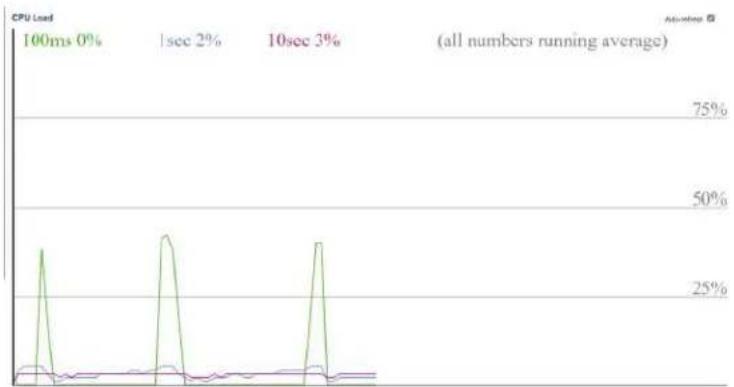
line
| Time Interval | CPU Load | | ------------- | -------- | | 0% | 75% | | 2% | 50% | | 3% | 25% |3.1.3 IP Interfaces/IP Status
This page displays the status of the IP protocol layer. The status is defined by the IP interfaces, the IP routes and the neighbor cache (ARP cache) status.
IP Interfaces
Interface
The name of the interface.
Type
The address type of the entry. This may be LINK or IPv4.
Address
The current address of the interface (of the given type).
Status
The status flags of the interface (and/or address). IP Routes
Network
The destination IP network or host address of this route.
Gateway
The gateway address of this route.
Status
The status flags of the route.
Neighbour cache
IP Address
The IP address of the entry.
Link Address
The Link (MAC) address for which a binding to the IP address given exist.
IP Interfaces
| Interface | Type | Address | Status |
| OS:lo | LINK | 00-00-00-00-00-00 | |
| OS:lo | IPv4 | 127.0.0.1/8 | |
| OS:lo | IPv6 | fe80::1/64 | |
| OS:lo | IPv6 | ::1/128 | |
| VLAN1 | LINK | 08-ed-02-59-20-41 | |
| VLAN1 | IPv4 | 192.168.1.130/24 | |
| VLAN1 | IPv6 | fe80::aed:2ff:fe59:2041/64 |
IP Routes
| Network | Gateway | Status |
| 127.0.0.1/32 | 127.0.0.1 | |
| 224.0.0.0/4 | 127.0.0.1 | |
| ::1/128 | ::1 |
Neighbour cache
| IP Address | Link Address |
| 192.163.1.100fe80::aed:2ff:fe59:2041 | VLAN1:00-e0-4c-78-94-f8VLAN1:08-ed-02-59-20-41 |
The system information log displays all programmed status changes as programmed by the operator in any of four-mode and all which displays all errors. Each level can be cleared individually or all.
You can view errors starting from and to any number
Auto-refresh □ Refresh Clear |<< << >> >>|
The two outer arrows are used to move to the first and last entry. The two middle ones increment one step up and down
3.1.4 System Information log
System Log Information
| Level | All | √ |
| Clear Level | All | √ |
| Auto-refresh | Refresh | Clear | |<< | << | >> | >>| |
The total number of entries is 4 for the given level.
Start from ID 1 with 20 entries per page.
| ID | Level | Time | Message |
| 1 | Informational | 12-02-2020T07:43:16-08:00 | SYS-BOOTING: Switch just made a cold boot. |
| 2 | Notice | 12-02-2020T07:43:22-08:00 | LINK-UPDOWN. Interface Van 1, changed state to down. |
| 3 | Notice | 12-02-2020T07:43:24-08:00 | LINK-UPDOWN. Interface GigabitEthernet 1/10, changed state to up. |
| 4 | Notice | 12-02-2020T07:43:25-08:00 | LINK-UPDOWN. Interface Van 1, changed state to up. |
Selecting an individual log entry will display the specific information for that entry
3.1.5 Detailed System Log Information
Detailed System Log Information
| ID | 1 |
Message
| Level | Informational |
| Time | 12-02-2020T07:43:16-08:00 |
| Message | SYS-BOOTING: Switch just made a cold boot. |
Green Ethernet
3.3 Green Ethernet > Port Power Savings
Local Port
This is the logical port number for this row.
Link
Shows if the link is up for the port (green = link up, red = link down).
EEE cap
Shows if the port is EEE capable.
EEE Ena
Shows if EEE is enabled for the port (reflects the settings at the Port Power Savings configuration page).
LP EEE cap
Shows if the link partner is EEE capable.
EEE In power save
Shows if the system is currently saving power due to EEE. When EEE is enabled, the system will powered down if no frame has been received or transmitted in 5 uSec.
Actiphy Savings
Shows if the system is currently saving power due to ActiPhy.
Port Power Savings Status
| Port | Link | EEE Cap | EEE Ena | LP EEE Cap | EEE In power save | ActiPhy Savings |
| 1 | √ | × | × | × | × | |
| 2 | √ | × | × | × | × | |
| 3 | √ | × | × | × | × | |
| 4 | √ | × | × | × | × | |
| 5 | √ | × | × | × | × | |
| 6 | √ | × | × | × | × | |
| 7 | √ | × | × | × | × | |
| 8 | √ | × | × | × | × | |
| 9 | √ | × | × | × | × | |
| 10 | √ | × | × | × | × | |
| 11 | × | × | × | × | × | |
| 12 | × | × | × | × | × |
This screen displays the temperature of each port and indicates if the port is operating within the proper temperature range. The upper port temperature range is 115C- The operator can program an lesser temperature
Thermal Protection Status
Thermal Protection Port Status
| Port | Temperature | Port status | |
| 1 | 47 | ^ | Port link operating normally |
| 2 | 47 | ^ | Port link operating normally |
| 3 | 47 | ^ | Port link operating normally |
| 4 | 47 | ^ | Port link operating normally |
| 5 | 47 | ^ | Port link operating normally |
| 6 | 47 | ^ | Port link operating normally |
| 7 | 47 | ^ | Port link operating normally |
| 8 | 47 | ^ | Port link operating normally |
| 9 | 47 | ^ | Port link operating normally |
| 10 | 47 | ^ | Port link operating normally |
| 11 | 47 | ^ | Port link operating normally |
| 12 | 47 | ^ | Port link operating normally |
3.3.1 Thermal Protection Status
Ports
3.4 Ports
A graphic image shows port status
The port states are illustrated as follows:
RJ45 ports
SFP ports
State

Disabled

Down

Link
3.4.1 State
Port State Overview

3.4.2 QoS Statistics
To determine performance traffic, refer to the following chart noting the Errors and Drops columns.
Port Statistics Overview
| Auto-refresh | Refresh | Clear |
| Port | Description | Packets | Bytes | Errors | Drops | Filtered | ||||
| Received | Transmitted | Received | Transmitted | Received | Transmitted | Received | Transmitted | Received | ||
| 1 | 36 | 79 | 29954 | 28266 | 0 | 0 | 0 | 0 | 0 | |
| 2 | 0 | 0 | 0 | 0 | 0 | 0 | 0 | 0 | 0 | |
| 3 | 0 | 0 | 0 | 0 | 0 | 0 | 0 | 0 | 0 | |
| 4 | 0 | 0 | 0 | 0 | 0 | 0 | 0 | 0 | 0 | |
| 5 | 0 | 0 | 0 | 0 | 0 | 0 | 0 | 0 | 0 | |
| 6 | 0 | 0 | 0 | 0 | 0 | 0 | 0 | 0 | 0 | |
| 7 | 0 | 0 | 0 | 0 | 0 | 0 | 0 | 0 | 0 | |
| 8 | 0 | 0 | 0 | 0 | 0 | 0 | 0 | 0 | 0 | |
| 9 | 0 | 0 | 0 | 0 | 0 | 0 | 0 | 0 | 0 | |
| 10 | 1419 | 705 | 298847 | 218845 | 0 | 0 | 0 | 0 | 644 | |
| 11 | 0 | 0 | 0 | 0 | 0 | 0 | 0 | 0 | 0 | |
| 12 | 0 | 0 | 0 | 0 | 0 | 0 | 0 | 0 | 0 | |
Q0 is the lowest priority- Q8 the highest for transmitting packets. The number of received and transmitted packets are shown for each queue.
3.4.3 Queuing Counters
Queuing Counters
| Port | Q0 | Q1 | Q2 | Q3 | Q4 | Q5 | Q6 | Q7 | ||||||||
| Rx | Tx | Rx | Tx | Rx | Tx | Rx | Tx | Rx | Tx | Rx | Tx | Rx | Tx | Rx | Tx | |
| 1 | 803 | 1465 | 0 | 803 | 0 | 0 | 0 | 0 | 0 | 0 | 0 | 0 | 0 | 0 | 0 | 13647 |
| 2 | 0 | 0 | 0 | 0 | 0 | 0 | 0 | 0 | 0 | 0 | 0 | 0 | 0 | 0 | 0 | 0 |
| 3 | 0 | 0 | 0 | 0 | 0 | 0 | 0 | 0 | 0 | 0 | 0 | 0 | 0 | 0 | 0 | 0 |
| 4 | 0 | 0 | 0 | 0 | 0 | 0 | 0 | 0 | 0 | 0 | 0 | 0 | 0 | 0 | 0 | 0 |
| 5 | 0 | 0 | 0 | 0 | 0 | 0 | 0 | 0 | 0 | 0 | 0 | 0 | 0 | 0 | 0 | 0 |
| 6 | 0 | 0 | 0 | 0 | 0 | 0 | 0 | 0 | 0 | 0 | 0 | 0 | 0 | 0 | 0 | 0 |
| 7 | 0 | 0 | 0 | 0 | 0 | 0 | 0 | 0 | 0 | 0 | 0 | 0 | 0 | 0 | 0 | 0 |
| 8 | 0 | 0 | 0 | 0 | 0 | 0 | 0 | 0 | 0 | 0 | 0 | 0 | 0 | 0 | 0 | 0 |
| 9 | 0 | 0 | 0 | 0 | 0 | 0 | 0 | 0 | 0 | 0 | 0 | 0 | 0 | 0 | 0 | 0 |
| 10 | 1910 | 217 | 0 | 0 | 0 | 0 | 0 | 0 | 0 | 0 | 0 | 0 | 0 | 0 | 0 | 1246 |
| 11 | 0 | 0 | 0 | 0 | 0 | 0 | 0 | 0 | 0 | 0 | 0 | 0 | 0 | 0 | 0 | 0 |
| 12 | 0 | 0 | 0 | 0 | 0 | 0 | 0 | 0 | 0 | 0 | 0 | 0 | 0 | 0 | 0 | 0 |
This chart shows the QCL or QoS Control List listing QCEs or QoS Control Entry. Each entry is associated with a specific traffic object within the QoS class. Frame recognition is based on the type of frame and information contained within the frame.
3.4.4 QCL Status
QoS Control List Status
| User | QCE | Port | Frame Type | Action | Conflict | |||||
| CoS | DPL | DSCP | PCP | DEI | Policy | |||||
| No entries | ||||||||||
3.4.5 Detailed Port Statistics
This feature provides a snapshot of transmission for an individual port
| Detailed Port Statistics Port 1 | ||
| Receive Total | Transmit Total | |
| Rx Packets | 0 Tx Packets | 0 |
| Rx Ootets | 0 Tx Ootets | 0 |
| Rx Unicast | 0 Tx Unicast | 0 |
| Rx Multicast | 0 Tx Multicast | 0 |
| Rx Broadcast | 0 Tx Broadcast | 0 |
| Rx Pause | 0 Tx Pause | 0 |
| Receive Size Counters | Transmit Size Counters | |
| Rx 64 Bytes | 0 Tx 64 Bytes | 0 |
| Rx 65-127 Bytes | 0 Tx 65-127 Bytes | 0 |
| Rx 128-265 Bytes | 0 Tx 128-265 Bytes | 0 |
| Rx 256-511 Bytes | 0 Tx 256-511 Bytes | 0 |
| Rx 612-1023 Bytes | 0 Tx 612-1023 Bytes | 0 |
| Rx 1024-1526 Bytes | 0 Tx 1024-1526 Bytes | 0 |
| Rx 1527- Bytes | 0 Tx 1527- Bytes | 0 |
| Receive Queue Counters | Transmit Queue Counters | |
| Rx Q0 | 0 Tx Q0 | 0 |
| Rx Q1 | 0 Tx Q1 | 0 |
| Rx Q2 | 0 Tx Q2 | 0 |
| Rx Q3 | 0 Tx Q3 | 0 |
| Rx Q4 | 0 Tx Q4 | 0 |
| Rx Q5 | 0 Tx Q5 | 0 |
| Rx Q6 | 0 Tx Q6 | 0 |
| Rx Q7 | 0 Tx Q7 | 0 |
| Receive Error Counters | Transmit Error Counters | |
| Rx Drops | 0 Tx Drops | 0 |
| Rx CRC/Alignment | 0 Tx Late/Exc. Coll. | 0 |
| Rx Undersize | 0 | |
| Rx Oversize | 0 | |
| Rx Fragments | 0 | |
| Rx Jabber | 0 | |
| Rx Filtered | 0 | |
3.5 Link OAM (Operations-Administration-Maintenance)
The link OAM can be view by selecting an individual port
| Detailed Link GAM Statistics for Port 1 | ||
| Port 1 ▼ Auto-refrsh □ Refins | ||
| Receive Total | Transmit Total | |
| Rx OAM Information PDU's | 0 Tx OAM Information PDU's | 0 |
| Rx Unique Error Event Notification | 0 Tx Unique Error Event Notification | 0 |
| Rx Duplicate Error Event Notification | 0 Tx Duplicate Error Event Notification | 0 |
| Rx Loopback Control | 0 Tx Loopback Control | 0 |
| Rx Variable Request | 0 Tx Variable Request | 0 |
| Rx Variable Response | 0 Tx Variable Response | 0 |
| Rx Org Specific PDU's | 0 Tx Org Specific PDU's | 0 |
| Rx Unsupported Codes | 0 Tx Unsupported Codes | 0 |
| Rx Link Fault PDU's | 0 Tx Link Fault PDU's | 0 |
| Rx Dying Gaep | 0 Tx Dying Gaep | 0 |
| Rx Critical Event PDU's | 0 Tx Critical Event PDU's | 0 |
3.5.1 Detailed Link OAM Statistics for Port
Receive Total and Transmit Total
Rx and Tx OAM Information PDU's
The number of received and transmitted OAM Information PDU's. Discontinuities of this counter can occur at re-initialization of the management system.
Rx and Tx Unique Error Event Notification
A count of the number of unique Event OAMPDUs received and transmitted on this interface. Event Notifications may be sent in duplicate to increase the probability of successfully being received, given the possibility that a frame may be lost in transit. Duplicate Event Notification transmissions are counted by Duplicate Event Notification counters for Tx and Rx respectively. A unique Event Notification OAMPDU is indicated as an Event Notification OAMPDU with a Sequence Number field that is distinct from the previously transmitted Event Notification OAMPDU Sequence Number.
Rx and Tx Duplicate Error Event Notification
A count of the number of duplicate Event OAMPDUs received and transmitted on this interface. Event Notification OAMPDUs may be sent in duplicate to increase the probability of successfully being received, given the possibility that a frame may be lost in transit. A duplicate Event Notification OAMPDU is indicated as an Event Notification OAMPDU with a Sequence Number field that is identical to the previously transmitted Event Notification OAMPDU Sequence Number.
Rx and Tx Loopback Control
A count of the number of Loopback Control OAMPDUs received and transmitted on this interface.
Rx and Tx Variable Request
A count of the number of Variable Request OAMPDUs received and transmitted on this interface.
Rx and Tx Variable Response
A count of the number of Variable Response OAMPDUs received and transmitted on this interface.
Rx and Tx Org Specific PDU's
A count of the number of Organization Specific OAMPDUs transmitted on this interface.
Rx and Tx Unsupported Codes
A count of the number of OAMPDUs transmitted on this interface with an unsupported op-code.
Rx and Tx Link fault PDU's
A count of the number of Link fault PDU's received and transmitted on this interface.
Rx and Tx Dying Gasp
A count of the number of Dying Gasp events received and transmitted on this interface.
Rx and Tx Critical Event PDU's
A count of the number of Critical events PDU's received and transmitted on this interface.
3.5.2 Detailed Link OAM Status for Port
This chart shows the OAM configuration for the selected ports displaying the programmed features for the OAM
| Detailed Link OAM Status for Port 1 | ||
| PDU Permission | Passive only | |
| Discovery State | Fault State | |
| Peer MAC Address | — | |
3.5.3 Detailed Link OAM Link Status for Port
This feature displays the current Lik OAM event configurations
| Local Frame Error Status | Remote Frame Error Status | ||
| Sequence Number | 0 | ||
| Frame Error Event Timestamps | 0 | Frame Error Event Timestamp | 0 |
| Frame error event window | 0 | Frame error event window | 0 |
| Frame error event threshold | 0 | Frame error event threshold | 0 |
| Frame errors | 0 | Frame errors | 0 |
| Total frame errors | 0 | Total frame errors | 0 |
| Total frame error events | 0 | Total frame error events | 0 |
| Local Frame Period Status | Remote Frame Period Status | ||
| Frame Period Error Event Timestamp | 0 | Frame Period Error Event Timestamp | 0 |
| Frame Period Error Event Window | 0 | Frame Period Error Event Window | 0 |
| Frame Period Error Event Threshold | 0 | Frame Period Error Event Threshold | 0 |
| Frame Period Errors | 0 | Frame Period Errors | 0 |
| Total frame period errors | 0 | Total frame period errors | 0 |
| Total frame period error events | 0 | Total frame period error events | 0 |
| Local Symbol Period Status | Remote Symbol Period States | ||
| Symbol Period Error Event Timestamp | 0 | Symbol Period Error Event Timestamp | 0 |
| Symbol Period Error Event Window | 0 | Symbol Period Error Event Window | 0 |
| Symbol Period Error Event Threshold | 0 | Symbol Period Error Event Threshold | 0 |
| Symbol Period Errors | 0 | Symbol Period Errors | 0 |
| Symbol frame period errors | 0 | Symbol frame perioderrors | 0 |
| Symbol frame period error events | 0 | Symbol frame perioderror events | 0 |
| Local Event Seconds Summary Status | Remote Event Seconds Summary Status | ||
| Event Seconds Summary Time Stamp | 0 | Event seconds Summary Time Stamp | 0 |
| Event Seconds Summary Window | 0 | Event seconds Summary Window | 0 |
| Event Seconds Summary Threshold | 0 | Event seconds Summary Threshold | 0 |
| Event Seconds Summary Events | 0 | Event Seconds Summary Events | 0 |
| Event Seconds Summary Error Total | 0 | Event Seconds Summary Error Total | 0 |
| Event Seconds Summary Event Total | 0 | Event Seconds Summary Event Total | 0 |
DHCP
3.6. DHCP Server
Dynamic Host Configuration Protocol where the DHCP server assigns the IP and network configuration for the connected devices.
3.6.1 DHCP Server Statistics
This feature displays the database counters and the number of DHCP messages send and received by the DHCP server
DHCP Server Statistics
Database Counters
| Pool | Excluded IP Address | Declined IP Address |
| 0 | 0 | 0 |
Binding Counters
| Automatic Binding | Manual Binding | Expired Binding |
| 0 | 0 | 0 |
DHCP Message Received Counters
| DISCOVER | REQUEST | DECLINE | RELEASE | INFORM |
| 0 | 0 | 0 | 0 | 0 |
DHCP Message Sent Counters
| OFFER | ACK | NAK |
| 0 | 0 | 0 |
3.6.2 DHCP Server Binding IP
This feature displays DHCP bindings which are generated for the DHCP network clients. You can locate the client address, server address type, and state of the binding with this feature.
| DHCP Server Binding IP | |||||
| Auto-refresh ☐ Refresh Clear Selected Clear Automatic Clear Manual Clear Expired | |||||
| Binding IP Address | |||||
| Delete | IP | Type | State | Pool Name | Server ID |
3.6.3 DHCP Server Declined IP
This feature shows a list of the IP client address of declined IP addresses by the DHCP server
DHCP Server Declined IP
Declined IP Address
| Declined IP |
3.6.4 Dynamic DHCP Snooping Table
This feature displays the dynamic IP assigned information after DHCP Snooping mode is disabled. All DHCP clients obtained the dynamic IP address from the DHCP server will be listed in this table except for local VLAN interface IP addresses. Entries in the Dynamic DHCP snooping Table are shown on this page
| Dynamic DHCP Snooping Table | ||||||||
| Start from MAC address: 00:00:00-10:00:00, VLAN() with 20 entries per page. | ||||||||
| MAC Address | VLAN ID | Source Port | IP Address | IP Subnet Mask | DHCP Server | |||
| No more entries | ||||||||
3.6.5 DHCP Relay Statistics
DHCP Relay Statistics
Server Statistics
| Transmit to Server | Transmit Error | Receive from Server | Receive Missing Agent Option | Receive Missing Circuit ID | Receive Missing Remote ID | Receive Bad Circuit ID | Receive Bad Remote ID |
| 0 | 0 | 0 | 0 | 0 | 0 | 0 | 0 |
Client Statistics
| Transmit to Client | Transmit Error | Receive from Client | Receive Agent Option | Replace Agent Option | Keep Agent Option | Drop Agent Option |
| 0 | 0 | 0 | 0 | 0 | 0 | 0 |
3.6.3 DHCP Detailed Statistics by Port
This feature provides statistics for DHCP Snooping. Note that the normal forward per-port TX statistics isn't increased if the incoming DHCP packet is done by L3 forwarding mechanism. And clear the statistics on specific port may not take effect on global statistics since it gathers the different layer overview
DHCP Detailed Statistics Port 1
| Receive Packets | Transmit Packets |
| Rx Discover | Tx Discover0 |
| Rx Offer | Tx Offer0 |
| Rx Request | Tx Request0 |
| Rx Decline | Tx Decline0 |
| Rx ACK | Tx ACK0 |
| Rx NAK | Tx NAK0 |
| Rx Release | Tx Release0 |
| Rx Inform | Tx Inform0 |
| Rx Lease Query | Tx Lease Query0 |
| Rx Lease Unassigned | Tx Lease Unassigned0 |
| Rx Lease Unknown | Tx Lease Unknown0 |
| Rx Lease Active | Tx Lease Active0 |
| Rx Discarded Checksum Error | 0 |
| Rx Discarded from Untrusted | 0 |
Security
3.7 Security
Security setting will tell you who and using what types of communications can access the switch
3.7.1 Access Management Statistics
Based on the configuration setting this will feature will tell the number of packets received, allowed and discarded. It a communications method was not allowed in the configuration setting all packets sent using that communications will be discarded.
Access Management Statistics
| Interface | Received Packets | Allowed Packets | Discarded Packets |
| HTTP | 0 | 0 | 0 |
| HTTPS | 0 | 0 | 0 |
| SNMP | 0 | 0 | 0 |
| TELNET | 0 | 0 | 0 |
| SSH | 0 | 0 | 0 |
3.7.2 Network
This page displays the various security modes programmed under Configuration to product unauthorized access over the network
3.7.3 Port Security
Port security displays security programming applied to an individual port
3.7.4 Port Security Switch Status
This feature shows the Port Security status. Port Security is a module with no direct configuration. Configuration comes indirectly from other modules - the user modules. When a user module has enabled port security on a port, the port is set-up for software-based learning. In this mode, packets from unknown MAC addresses are passed on to the port security module, which in turn asks all user connected devices whether to allow this new MAC address to forward or block it. For a MAC address to be set in the forwarding state, all enabled user devices must unanimously agree on allowing the MAC address to forward. If only one feature chooses to block it, it will be blocked until that user programmed feature decides otherwise.
The status page is divided into two sections - one with a legend of user modules and one with the actual port status.
Port Security Switch Status
User Module Legend
| User Module Name | Abbr |
| Limit Control | L |
| 802 1X | 8 |
| Voice VLAN | V |
Port Status
| Port | Users | State | MAC Count | |
| Current | Limit | |||
| 1 | --- | Disabled | - | - |
| 2 | --- | Disabled | - | - |
| 3 | --- | Disabled | - | - |
| 4 | --- | Disabled | - | - |
| 5 | --- | Disabled | - | - |
| 6 | --- | Disabled | - | - |
| 7 | --- | Disabled | - | - |
| 8 | --- | Disabled | - | - |
| 9 | --- | Disabled | - | - |
| 10 | --- | Disabled | - | - |
| 11 | --- | Disabled | - | - |
| 12 | --- | Disabled | - | - |
3.7.4.1 Port Security – Individual port status
This feature shows the individual MAC address which is secured b the programmed Port Security selected module
3.7.4.2 NAS
Port Security Port Status Port 1
| MAC Address | VLAN ID | State | Time of Addition | Age/Hold |
| No MAC addresses attached | ||||
NAS is an acronym for Network Access Server. The NAS is meant to act as a gateway to guard access to a protected source. A client connects to the NAS, and the NAS connects to another resource asking whether the client's supplied credentials are valid. Based on the answer, the NAS then allows or disallows access to the protected resource. An example of a NAS implementation is IEEE 802.1X.
3.7.4.3. Network Access Server Switch Status
This feature displays individual Port NAS status
Network Access Server Switch Status
| Port | Admin State | Port State | Last Source | Last ID | QoS Class | Port VLAN ID |
| 1 | Force Authorized | Globally Disabled | - | |||
| 2 | Force Authorized | Globally Disabled | - | |||
| 3 | Force Authorized | Globally Disabled | - | |||
| 4 | Force Authorized | Globally Disabled | - | |||
| 5 | Force Authorized | Globally Disabled | - | |||
| 6 | Force Authorized | Globally Disabled | - | |||
| 7 | Force Authorized | Globally Disabled | - | |||
| 8 | Force Authorized | Globally Disabled | - | |||
| 9 | Force Authorized | Globally Disabled | - | |||
| 10 | Force Authorized | Globally Disabled | - | |||
| 11 | Force Authorized | Globally Disabled | - | |||
| 12 | Force Authorized | Globally Disabled | - |
3.7.4.4 Individual NAS Statistics
This feature displays individual Port NAS status
NAS Statistics Port 1
Port State
| Admin State Port State | Force Authorized Globally Disabled |
3.7.4.5 ACL Status
ACL stands for Access Control List and is defined by listing of ACEs which is Access Control Entries which specify users and groups allowed or denied specific types of traffic which can be in the form of a process or program ACEs are composed of the items listed in the ACL status
ACL Status
| User | ACE | Frame Type | Action | Rate Limiter | Mirror | CPU | Counter | Conflict |
| upnp | 1 | IPv4/UDP 1900 | Permt | Disabled | Disabled | Yes | 331 | No |
| upnp | 2 | IPv4 DIP.224.0.0.1/32 | Permt | Disabled | Disabled | Yes | 0 | No |
3.7.4.6 ARP Inspection
ARP stands for Address Resolution Protocol which maps a dynamic (changing) IP address to connected device IP address on a local area network (LAN)
In the table below up to 20 addresses can be displayed sorted first by the port number, then the VLAN ID it is programmed to, followed by the MAC Address and finally the IP address. The starting range for all of these can be programmed by the operator. The dynamic entry is learned from DHCP programming
Dynamic ARP Inspection Table
| Port | VLAN ID | MAC Address | IP Address |
| No more entries | |||
3.7.4.7 Dynamic IP Source Guard Table
This feature displays the individual port entries as Dynamic (changing) IP addresses showing which IP addresses are blocked and their associated port, VLAN. The operator can enter the starting IP address and the number of entries up to 20 to displayed
Dynamic IP Source Guard Table

Aggregation
3.8 Aggregation
Aggregation is a process where multiple ports are used in parallel to increase the port speed beyond the limit of the individual port. It can also be used to create redundancy.
3.8.1 Aggregation Status
This feature shows which ports and their collective speed that are members of aggregated ports
Aggregation Status
| Aggr ID | Name | Type | Speed | Configured Ports | Aggregated Ports |
| No aggregation groups | |||||
3.8.2 LACP
LACP stands for Link Aggregation Control Protocol which forms several ports in a single logic port. Its operation is defined by IEEE 802.3ad.
3.8.3 LACP System Status
This table shows the various parts of the LACP. The partner system ID is defined by the system MAC and local ports show a listing of all the ports which are part of the LACP
LACP System Status
| Aggr ID | Partner System ID | Partner Key | Partner Prio | Last Changed | Local Ports |
| No ports enabled or no existing partners | |||||
3.8.4 LACP Status
This feature displays the LACP status for all the ports
LACP Status
| Port | LACP | Key | Aggr ID | Partner System ID | Partner Port | Partner Prio |
| 1 | No | - | - | - | - | - |
| 2 | No | - | - | - | - | - |
| 3 | No | - | - | - | - | - |
| 4 | No | - | - | - | - | - |
| 5 | No | - | - | - | - | - |
| 6 | No | - | - | - | - | - |
| 7 | No | - | - | - | - | - |
| 8 | No | - | - | - | - | - |
| 9 | No | - | - | - | - | - |
| 10 | No | - | - | - | - | - |
| 11 | No | - | - | - | - | - |
| 12 | No | - | - | - | - | - |
The feature shows per port the number of LACP Received, Transmitted, and Discarded
8.2.3 LACP Statics
LACP Statistics
| Port | LACP Received | LACP Transmitted | Discarded | |
| Unknown | Illegal | |||
| 1 | 0 | 0 | 0 | 0 |
| 2 | 0 | 0 | 0 | 0 |
| 3 | 0 | 0 | 0 | 0 |
| 4 | 0 | 0 | 0 | 0 |
| 5 | 0 | 0 | 0 | 0 |
| 6 | 0 | 0 | 0 | 0 |
| 7 | 0 | 0 | 0 | 0 |
| 8 | 0 | 0 | 0 | 0 |
| 9 | 0 | 0 | 0 | 0 |
| 10 | 0 | 0 | 0 | 0 |
| 11 | 0 | 0 | 0 | 0 |
| 12 | 0 | 0 | 0 | 0 |
Loop Protection
3.9 Loop Protection Status
Loop protection prevents ports involved in STP, RSTP and MSTP from moving to a port forwarding state increasing the potential in a loop opening up. STP protocol loop protection helps with normal checks containing spanning protocols performed on their interfaces.
Loop Protection Status
| Port | Action | Transmit | Loops | Status | Loop | Time of Last Loop |
| No ports enabled | ||||||
Spanning Tree
3.10 Spanning Tree
Spanning tree protocol (STP) is a Layer 2 network protocol used to prevent looping within a network topology. STP was created to avoid the problems that arise when computers compete for the ability to use the shared data path on a local area network (LAN). When too many computers try to send at the same time, overall network performance is affected and can bring all traffic to a near halt.
The Bridge is a snapshot of the current STP state and connections
3.10.1 STP Bridge Status
STP Bridges
| MSTI | Bridge ID | Root | TopologyFlag | TopologyChange Last | ||
| ID | Port | Cost | ||||
| CIST | 32768.08-ED-02-59-20-41 | 32768.08-ED-02-59-20-41 | - | 0 | Steady | - |
STI
The Bridge Instance. This is also a link to the STP Detailed Bridge Status.
Bridge ID
The Bridge ID of this Bridge instance.
Root ID
The Bridge ID of the currently elected root bridge.
Root Port
The switch port currently assigned the root port role.
Root Cost
Root Path Cost. For the Root Bridge it is zero. For all other Bridges, it is the sum of the Port Path Costs on the least cost path to the Root Bridge.
Topology Flag
The current state of the Topology Change Flag of this Bridge instance.
Topology Change Last
The time since last Topology Change occurred.
3.10.2 STP Port Status
This show the state of any individual port
STP Port Status
| Port | CIST Role | CIST State | Uptime |
| 1 | Non-STP | Forwarding | - |
| 2 | Non-STP | Forwarding | - |
| 3 | Non-STP | Forwarding | - |
| 4 | Non-STP | Forwarding | - |
| 5 | Non-STP | Forwarding | - |
| 6 | Non-STP | Forwarding | - |
| 7 | Non-STP | Forwarding | - |
| 8 | Non-STP | Forwarding | - |
| 9 | Non-STP | Forwarding | - |
| 10 | Non-STP | Forwarding | - |
| 11 | Non-STP | Forwarding | - |
| 12 | Non-STP | Forwarding | - |
CIST stands for Common Internal Spanning Tree and notes areas in a network for administrating the bridge for a network. The chart will show when ports and their state as part of the VLAN. Membership is defined by the CIST Role. CIST State can be Forwarding, Leaning or Discarding
3.10.2 STP Port Statu3.10.3 STP Statistics
This feature measures the BPDU (Bridge Protocol Data Unit) which contains a port, switch, port priority, and addresses required to maintain the Spanning Tree.
STP Statistics
| Port | Transmitted | Received | Discarded | |||||||
| MSTP | RSTP | STP | TCN | MSTP | RSTP | STP | TCN | Unknown | Illegal | |
| No ports enabled | ||||||||||
IPMC - IGMP
3.11 IPMC
IPMC (Internet Protocol Multimedia Communications) is used to register multicasting groups when the received packet contains an IGMP/MLD control message for support of multi-point communications within a network.
3.11.1 IGMP Snooping
IGMP Snooping is the proceeds of listening to Internet Group Management Protocol (IGMP) which controls network traffic for the delivery of multicast packets. The process listens to the transmission between the host and clients which can include routers to traffic packets.
3.11.2 IGMP Snooping Status
This feature defines the Querier version, Host version followed by the number of Queries as defined by the those columns.
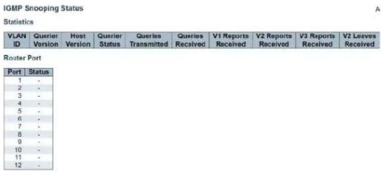
This feature references to a specific VLAN followed by the group address assigned to the VLAN and the ports contained. Note the multicast IP ranges from 224.0.0.0 to 239.255.255.255
3.11.3 IGMP Snooping Group Information
IGMP Snooping Group Information

3.11.4 IGMP SFM Information
SFM is defined as Source-Filtered- Multicast which allows different source addresses to be contained within a single entry within a one group.
IGMP SFM Information

LLDP
3.12 LLDP
LLDP (Link Layer Discovery Protocol) allows connected devices to inform the host of their identity on the network and in many cases provide information about their status and requirements. To be effective the host must be able to read the LLDP from the connected device. The general definition of this function is contained in IEEE 802.1AB
3.12.1 LLDP Neighbor Information
LLDP can only be read if the connected device transmits LLDP that can be read by the host. Some products have built in standard LLDPs which if contained will be identified under the System Capabilities column
LLDP Neighbor Information
| LLDP Remote Device Summary | ||||||
| Local interface | Chassis ID | Port ID | Port Description | System Name | System Capabilities | Management Address |
| No neighbor information found | ||||||
3.12.2 LLDP MED Neighbor Information
This feature will display the LLDP devices which there are several potential capabilities including the ability to detect and measure PoE PSE (Source power) and PoE device power (PD) the connect device must have the ability compliant to the communications standards.
LLDP-MED Neighbor Information
| Local Interface |
| No LLDP-MED neighbor information found |
3.12.3 LLDP Neighbors EEE Information
EEE is the power-saving standard which is programmed in the Configuration section. It monitors the power provided by a port based on packet transmission which is usually tied to latency. Using EEE can result in a port shut down depending on the connected device and is not recommended for security applications
The chart will include if the LLDP function can read the EEE from the connected devices.
LLDP Neighbors EEE Information
Auto-refresh
| Local Interface | Tx Tw | Rx Tw | Fallback Receive Tw | Echo Tx Tw | Echo Rx Tw | Resolved Tx Tw | Resolved Rx Tw | EEE in Sync |
| No LLDP EEE information found | ||||||||
3.12.4 LLDP Global Counters
This feature shows both Global counters which refer to the switch while the local counters who's traffic from the individual port
LLDP Global Counters
Auto-rebeach □ Refle
| Global Counters | |
| Clear global counts | ☑ |
| Neighbor entries were last changed: 12-04-2020T31/26.23-08.90 (6461 secs. ag) | |
| Total Neighbors Entries Added | 0 |
| Total Neighbors Entries Deleted | 0 |
| Total Neighbors Entries Drapped | 0 |
| Total Neighbors Entries Aged Out | 0 |
LLDP Statistics Local Counters
| Local Interface | Tx Frames | Rx Frames | Rx Errors | Frames Discarded | TxVs Discarded | TxVs Unrecognized | Org. Discarded | Age-Outs | Clear |
| GigabitEthernet 1/1 | 0 | 0 | 0 | 0 | 0 | 0 | 0 | 0 | 0 |
| GigabitEthernet 1/2 | 0 | 0 | 0 | 0 | 0 | 0 | 0 | 0 | 0 |
| GigabitEthernet 1/3 | 0 | 0 | 0 | 0 | 0 | 0 | 0 | 0 | 0 |
| GigabitEthernet 1/4 | 0 | 0 | 0 | 0 | 0 | 0 | 0 | 0 | 0 |
| GigabitEthernet 1/5 | 0 | 0 | 0 | 0 | 0 | 0 | 0 | 0 | 0 |
| GigabitEthernet 1/6 | 0 | 0 | 0 | 0 | 0 | 0 | 0 | 0 | 0 |
| GigabitEthernet 1/7 | 0 | 0 | 0 | 0 | 0 | 0 | 0 | 0 | 0 |
| GigabitEthernet 1/8 | 0 | 0 | 0 | 0 | 0 | 0 | 0 | 0 | 0 |
| GigabitEthernet 1/9 | 0 | 0 | 0 | 0 | 0 | 0 | 0 | 0 | 0 |
| GigabitEthernet 1/10 | 218 | 0 | 0 | 0 | 0 | 0 | 0 | 0 | 0 |
| 2.5GigabitEthernet 1/1 | 0 | 0 | 0 | 0 | 0 | 0 | 0 | 0 | 0 |
| 2.5GigabitEthernet 1/2 | 0 | 0 | 0 | 0 | 0 | 0 | 0 | 0 | 0 |
EVC stands for Ethernet Virtual Connection which describes the services provide over User Network Interfaces. This is a Cisco related function to select and manage inbound 802.1q VLAN Tags. It helps
Ethernet Services
3.13. Ethernet Services
3.13.1 EVC Statistics
to define the action to be taken based on the frame information. In order to work all switches within a network must be EVC capable
EVC Statistics
| Class | Green Frames | Yellow Frames | Red Frames | Discarded Frames | |||
| Rx | Tx | Rx | Tx | Rx | Green | Yellow | |
| 0 | 0 | 0 | 0 | 0 | 0 | 0 | 0 |
| 1 | 0 | 0 | 0 | 0 | 0 | 0 | 0 |
| 2 | 0 | 0 | 0 | 0 | 0 | 0 | 0 |
| 3 | 0 | 0 | 0 | 0 | 0 | 0 | 0 |
| 4 | 0 | 0 | 0 | 0 | 0 | 0 | 0 |
| 5 | 0 | 0 | 0 | 0 | 0 | 0 | 0 |
| 6 | 0 | 0 | 0 | 0 | 0 | 0 | 0 |
| 7 | 0 | 0 | 0 | 0 | 0 | 0 | 0 |
3.13.2 PoE: Power Over Ethernet Status
This feature shows the PoE status for each port – Power allocated and Priority will depend upon the user programming.
Power Over Ethernet Status
| Local Port | PD class | Power Allocated | Power Used | Current Used | Voltage Used | Priority | Port Status |
| 1 | - | 0 [W] | 0 [W] | 0 [mA] | 0 [V] | Low | No PD detected |
| 2 | - | 0 [W] | 0 [W] | 0 [mA] | 0 [V] | Low | No PD detected |
| 3 | - | 0 [W] | 0 [W] | 0 [mA] | 0 [V] | Low | No PD detected |
| 4 | - | 0 [W] | 0 [W] | 0 [mA] | 0 [V] | Low | No PD detected |
| 5 | - | 0 [W] | 0 [W] | 0 [mA] | 0 [V] | Low | No PD detected |
| 6 | - | 0 [W] | 0 [W] | 0 [mA] | 0 [V] | Low | No PD detected |
| 7 | - | 0 [W] | 0 [W] | 0 [mA] | 0 [V] | Low | No PD detected |
| 8 | - | 0 [W] | 0 [W] | 0 [mA] | 0 [V] | Low | No PD detected |
| Total | 0 [W] | 0 [W] | 0 [mA] |
3.13.3 MAC Address Table
The table shows the MAC addresses for the connected devices both for individual connections and connects as part of the programmed VLAN. You can program a selected VLAN and starting MAC address
MAC Address Table
| Start from VLAN | 1 | and MAC address | 00-00-00-00-00-00 | with | 20 | entries per page. |
| Port Members | |||||||||||||||
| Type | VLAN | MAC Address | CPU | 1 | 2 | 3 | 4 | 5 | 6 | 7 | 8 | 9 | 10 | 11 | 12 |
| Dynamic | 1 | 00-42-48-66-15-94 | √ | ||||||||||||
| Dynamic | 1 | 00-E3-4C-7B-94-F9 | √ | ||||||||||||
| Static | 1 | 08-E0-02-59-20-41 | √ | ||||||||||||
| Static | 1 | 33-33-00-00-00-01 | √ | √ | √ | √ | √ | √ | √ | √ | √ | √ | |||
| Static | 1 | 33-33-00-00-00-02 | √ | √ | √ | √ | √ | √ | √ | √ | √ | √ | √ | √ | |
| Static | 1 | 33-33-FF-59-20-41 | √ | √ | √ | √ | √ | √ | √ | √ | |||||
| Static | 1 | FF-FF-FF-FF-FF-FF | √ | √ | √ | √ | √ | √ | √ | √ | √ | √ | √ | √ | |
VLANs allow us to create individual networks within the switch so that specific ports can be segregated to carry specific signals
This feature displays the ports assigned to each VLAN
VLAN Membership Status for Combined users
Start from VLAN 1 with 20 entries per page. |<< >>
| Port Members | ||||||||||||
| VLAN ID | 1 | 2 | 3 | 4 | 5 | 6 | 7 | 8 | 9 | 10 | 11 | 12 |
| 1 | √ | √ | √ | √ | √ | √ | √ | √ | √ | √ | √ | √ |
VLANs
3.14 VLAN
3.14.1 VLAN
Membership Status
for Combined users
3.14.2 VLAN Port
Status for Combined
users
The drop-down menu showing admin is used to select the type of viewer for the chart. Combined will show all types of users from internal programmed software and hardware modules.
The port type will show the type of port in use as configured by the operator- This screen is monitoring only
VLAN Port Status for Admin user
| Port | Port Type | Ingress Filtering | Frame Type | Port VLAN ID | Tx Tag | Untagged VLAN ID | Conflicts |
| 1 | C-Port | ☑ | All | 1 | Untag All | No | |
| 2 | C-Port | ☑ | All | 1 | Untag All | No | |
| 3 | C-Port | ☑ | All | 1 | Untag All | No | |
| 4 | C-Port | ☑ | All | 1 | Untag All | No | |
| 5 | C-Port | ☑ | All | 1 | Untag All | No | |
| 6 | C-Port | ☑ | All | 1 | Untag All | No | |
| 7 | C-Port | ☑ | All | 1 | Untag All | No | |
| 8 | C-Port | ☑ | All | 1 | Untag All | No | |
| 9 | C-Port | ☑ | All | 1 | Untag All | No | |
| 10 | C-Port | ☑ | All | 1 | Untag All | No | |
| 11 | C-Port | ☑ | All | 1 | Untag All | No | |
| 12 | C-Port | ☑ | All | 1 | Untag All | No |

sFlow is used to monitoring packet samples on ports based on an internal time-based sample as they are sent to a central network traffic monitoring server which is known as SFlow collector or receiver it is an industry standard but not used by every switch
3.15 sFlow Statistics
sFlow
3.15 sFlow Statistics
sFlow Statistics
Receiver Statistics
| Owner | |
| IP Address/Hostname | 0.0.0.0 |
| Timeout | 0 |
| Tx Successes | 0 |
| Tx Errors | 0 |
| Flow Samples | 0 |
| Counter Samples | 0 |
Port Statistics
| Port | Flow Samples | Counter Samples |
| 1 | 0 | 0 |
| 2 | 0 | 0 |
| 3 | 0 | 0 |
| 4 | 0 | 0 |
| 5 | 0 | 0 |
| 6 | 0 | 0 |
| 7 | 0 | 0 |
| 8 | 0 | 0 |
| 9 | 0 | 0 |
| 10 | 0 | 0 |
| 11 | 0 | 0 |
| 12 | 0 | 0 |
UDLD
3.16 UDLD
UDLD stands for Uni Directional Link Detection. This protocol monitors a link to devices that support this protocol. It is a Cisco protocol used to detect UDP links to prevent forwarding loops. Problems in this area are indications of cable problems.
Detailed UDLD Status for Port 10
| UDLD status | |
| UDLD Admin state | Disable |
| Device ID(local) | 08-ED-02-59-20-41 |
| Device Name(local) | - |
| Bidirectional State | Indeterminant |
Neighbour Status
| Port | Device Id | Link Status | Device Name |
| No Neighbour ports enabled or no existing partners | |||
Chapter 4: Diagnostic
4. Diagnostic
Diagnostics
■ Ping
Link OAM
- Ping6
4.1.1 Ping
ICMP Ping
IP Address
Ping Length
Ping Count
Ping Interval
| 0.0.0.0 |
| 56 |
| 5 |
| 1 |
Start
Packet size is limited to 1452 bytes
• IP Address: enter the IP address you want to ping.
• Ping Length: The length of data packet.
• Ping Count: The quantity of packet sent back
• Ping Interval: the time interval between each ping request
•
4.1.2 Link OAM
4.1.3 MIB Retrieval
Link OAM MIB Retrieval
Local
Peer
Port


Start
• This configuration page allows you to retrieve local or remote OAM MIB variable data on a specific port.
- Select the appropriate radio button and enter the port number of the switch to retrieve the interested content.
- Click "Start" to retrieve the content.
4.1.4 Ping v6
ICMPv6 Ping
| IP Address | 0:00:00:00:0 |
| Ping Length | 56 |
| Ping Count | 5 |
| Ping Interval | 1 |
| Egress Interface |
Start
• IP Address: enter the IP address you want to ping.
• Ping Length: The length of the data packet.
• Ping Count: The quantity of packet sent back
• Ping Interval: the time interval between each ping request.
Chapter 5: Maintenance
5. Maintenance
diagnostics
Maintenance
- Restart Device
- Factory Defaults
▼ Software
- Upload
■ Image Select
Configuration
■ Save startup-config
■ Download
- Upload
■Activate
Delete
Restart Device

5.1.1 Restart Device
Click "YES" to restart device, Click NO to cancel restart.
5.1.2 Factory Defaults
Factory Defaults

Click YES to reset the configuration to factory defaults, Click NO will cancel to reset the configuration to factory defaults.
Software
5.2 Software
▼ Software
- Upload
■ Image Select
5.2.1 Upload
Software Upload
Browse...
No file selected.
Upload
Click "browse" button, Find the upgrade firmware in the local disk and click "Upload" to update the firmware operation.
5.2.2 Image Select
Software Image Selection
| Active Image | |
| Image | ce_switch_caracal1_l10_ref.dat |
| Version | CEServicesCEServices---V1.00 |
| Date | 09-2019 |
| Alternate Image | |
| Image | ce_switch_caracal1_l10_ref.dat |
| Version | CEServicesCEServices--V1.00 |
| Date | 09-2019 |
Activate Alternate Image
Cancel
5.2.3 Configuration
Save Running Configuration to startup-config
5.2.4 Save startup-config
Please note: The generation of the configuration file may be time consuming, depending on the amount of non-default configuration.
Save Configuration
5.2.5 Download
Download Configuration
Select configuration file to save.
Please note: running-config may take a while to prepare for download.
| File Name |
| ○ running-config |
| ○ default-config |
| ○ startup-config |
Download Configuration
- Running-Config is Running Profile
• Default-Config is Default Profile - Startup-Config is Startup Profile
Click anyone of them then click" Download Configuration" to save to local disk.
Configuration
5.3 Upload Configuration
Upload Configuration
File To Upload
Browse...
No file selected.
Destination File
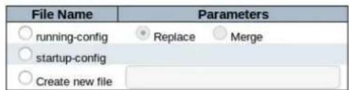
Upload Configuration
Click "browse" button, Find the corresponding profiles in the local disk, and select the corresponding Profiles in the "File Name" column.
Click "Upload Configuration" upload to switch.
5.3.1 Activate
Activate Configuration
Select configuration file to activate. The previous configuration will be completely replaced, potentially leading to loss of management connectivity.
Please note: The activated configuration file will not be saved to startup-config automatically.
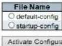
In addition to representing running configuration of active configuration, any configuration files on the switch can be activated. Select the file which needs to activate and click, then click "Activate Configuration"
- It will initiate the process of replacing the existing configuration with the selected configuration file.
5.3.2 Delete
Delete Configuration File
Select configuration file to delete.
Delete Configuration File
Click "Startup-Config" then click "Delete Configuration File" can delete configuration file of switch.
How to modify the device IP address, the detail is shown in the below:
Steps 1: as follow picture 3
5.3.3 Chapter Five Appendix

Steps 2: as follow picture 4 Enter a new IP address in IE and find the click-save configuration shown in Figure 4 below
5.3.4 Appendix1 Modify the device IP address

5.3.5 Appendix2 VLAN Configuration
VLANS Configuration as follow picture 28

- Step 1: Click menu "Configuration" --- "VLANS" enter into Vlans configuration page, Grey box means Default Configuration.
- Step 2: Select the access mode, the default access mode of the device is "Access", and the other two modes are "Trunk" and "Hybrid".
Access: Port type can only belong to 1 Vlan, usually used to connect to a computer.
Trunk: Port type allows multiple VLANs to pass, it can receive and send message of multiple VLSNs, usually used to connect the port between switch.
Hybrid: Port type allows multiple VLANs to pass, it can receive and send message of multiple VLSNs, can be used to connect between switches, or to connect to a user's computer.
- Step 3: Enter corresponding VLAN ID in "Port VLAN". The valid range that can be entered is 1-4095.
• Step 4: Save configuration information, as shown in picture 4 below.
5.3.6 Appendix3 ERPS configuration
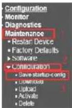
Save Running Configuration to startup-config
Please note: The generation of the configuration file may be time consuming, depending on the amount of non-default configuration.

Network topology:
5.3.7 ERPS Monocyclic configuration

flowchart
Network topology diagram showing interconnected devices (SW1, SW2, SW3) with port labels and connections to RPL-Owner and None, including a tagged VID=100 for ERPS monocyclic.5.3.8 VLANS Configuration
IP Address Configuration:
Modify the IP address of SW#1, SW#2 and SW#3, such as 192.0.3.200-192.0.3.202, Please refer to appendix 1 for the detail.
5.3.9 STP Configuration
STP Configuration:
SW#1, SW#2, SW#3 STP Configuration: as follow picture 6
1/ forbidden STP. The device's factory default is enabled. /Click "save" to save.

SW#1, SW#2, SW#3 VLANS Configuration As follow picture

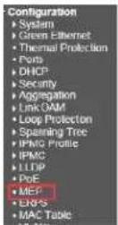
5.3.10 MEP configuration
SW#1 MEP configuration Step 1: As follow picture 7
Maintenance Entity Point

Picture 7
SW#1 MEP configuration Step 2: As follow picture 8
Maintenance Entity Point
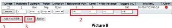
SW#1 MEP configuration Step 3: As follow picture 9
Maintenance Entity Point

SW#1 MEP configuration Step 4: As follow picture
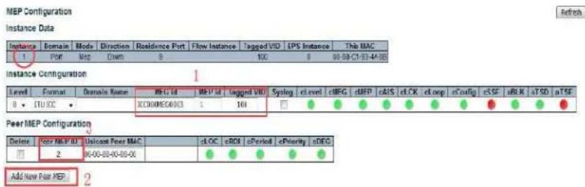
Functional Configuration
| Continuity Check | APS Protocol | ||||||||
| Enable | Priority | Frame rate | TLV | Enable | Priority | Cast | Type | Last Octol | |
| ☑ | 0 | 17:36 | √ | ☐ | ☑ | 0 | Malt ▼ | R-APS ▼ 1 | |
| Fault Management | Performance Monitoring | 4 |
| Organization Specific TLV (Global) | ||||
| OUI First | OUI Second | OUI Third | Sub-Type | Value |
| 0 | 0 | 12 | 1 | 2 |
TLV Status
| Peer MCP ID | CC Organization Specific | CC Port Status | CC Interface Status | |||||||
| Old First | Old Second | Old Third | Sub.Type | Value | Last RX | Value | Last RX | Value | Last RX | |
| 2 | 0 | 0 | 0 | 0 | 0 | ● | 0 | ● | 0 | ● |
SW#1 MEP configuration Step 5: As follow picture

Functional Configuration
| Continuity Check | APS Protocol | ||||||||
| Enable | Priority | Frame rate | TLV | Enable | Priority | Cast | Trio | Last Octal | |
| √ | 0 | 1/sec | □ | √ | 0 | Rubi | F-APS | 1 | |
TLV Configuration
| Organization Specific TLV (Global) | ||||
| OU First | OU Second | OU Third | Sub Type | Value |
| 0 | 0 | 12 | 1 | 2 |
TLV Status
| Peer MEF ID | CC Organization Specific | CC Port Status | CC Interface Status | |||||||||
| OUT First | OUT Second | OUT Third | Sub-Type | Value | Last RX | Value | Last RX | Value | Last RX | |||
| 2 | 0 | 0 | 0 | 0 | 0 | 0 | 0 | 0 | 0 | 0 | ||
Link State Tracking
| Enable |
| 5 |
| Save Reset |
SW#2 MEP configuration Step 1: As follow picture 7
Maintenance Entity Point
| Delete | Instance | Domain | Mode | Direction | Residence Port | Level | Flow/Instance | Tagged VIO | This MAC | Alarm |
| Delete | 1 | Port | Mep | Down | 9 | 0 | 9 | 100 | ||
| Add New MEP | Save | Reset | ||||||||
Picture 7
SW#2 MEP configuration Step 2: As follow picture 8
Maintenance Entity Point
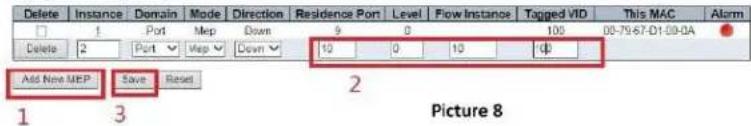
SW#2 MEP configuration Step 3: As follow picture 9
Maintenance Entity Point
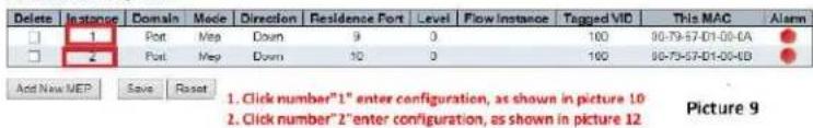
SW#2 MEP configuration Step 4: As follow picture

Functional Configuration

TLY Configuration

TLY Status

SW#2 MEP configuration Step 5: As follow picture

Functional Configuration
| Continuous Check | APS Protocol | ||||||||
| Enable | Priority | Frame rate | TLV | Enable | Priority | Cast | Type | Last Order | |
| ☑ | 0 | 1 Psec | ☐ | ☑ | 0 | Multi | R-APS | 1 | |
Fault Management Performance Monitoring 4
TLV Configuration
| Organization Specific TLV (Global) | ||||
| OUI First | OUI Second | OUI Third | Sub type | Value |
| 0 | 0 | 12 | 1 | 2 |
TLV Status
| Peer MEP ID | CC Organization Specific | CC Port Status | CC Interface Status | |||||||||
| OUT First | OUT Second | OUT Third | Sub-Type | Value | Last RX | Value | Last RX | Value | Last RX | |||
| 2 | 0 | 0 | 0 | 0 | 0 | ● | 0 | ● | 0 | ● | ||
Link State Tracking

SW#3 MEP configuration Step 1: As follow picture 7
Maintenance Entity Point

Picture 7
SW#3 MEP configuration Step 2: As follow picture 8
Maintenance Entity Point

SW#3 MEP configuration Step 3: As follow picture 9
Maintenance Entity Point
| Delete | Instance | Domain | Mode | Direction | Residence Port | Level | Flow Instance | Tagged VID | This MAC | Alarm |
| 1 | Port | Map | Down | 9 | 0 | 100 | 00-79-67-D1-00-0A | |||
| 2 | Port | Map | Down | 10 | 0 | 100 | 00-79-67-D1-00-0D |
Add New MEP Save Reset 1. Click number "1" enter configuration, as shown in picture 10 2. Click number "2" enter configuration, as shown in picture 12 Picture 9
SW#3 MEP configuration Step 4: As follow picture
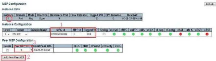
Functional Configuration
| Continuity Check | APS Protocol | ||||||||
| Enable | Priority | Frame rate | TLV | Enable | Priority | Cast | Type | Last Octat | |
| ☑ | 0 | 1 F=c | ▼ | □ | ☑ | 0 | Multi▼ | R-APS▼ | 1 |
Fault Management
Performance Monitoring
4
TLV Configuration
| Organization Specific TLV (Global) | ||||
| CUI First | CUI Second | OUI Third | Sub-type | Value |
| 0 | 0 | 12 | 1 | 2 |
TLV Status
| Peer MEP ID | CC Organization Specific | CC Post Status | CC Interface Status | |||||||||
| OUI First | OUI Second | OUI Third | Sub-Type | Value | Last RX | Value | Last RX | Value | Last RX | |||
| 2 | 0 | 0 | 0 | 0 | 0 | ● | 0 | ● | 0 | ● | ||
Link State Tracking

SW#3 MEP configuration Step 5: As follow picture
MEP Configuration
Recrest
instance Data
| Instance | Domains | Mode | Direction | Residence Port | Flow Instance | Tagged VD | EPS Instance | This MMC |
| 1 | Port | Map | Down | 10 | 100 | 0 | 30.00 € 02-45.00 |
Instance Configuration
| Level | Format | Domain Name | MEG_id | MEP_id | Tagged_VID | Systlog | cLevel | cMEG | cMTP | cAIS | cLOX | cLcop | cConfig | cSSF | aBLX | aTSD | aTSE |
| 0 | ITU/JCC | CC000KG0003 | 2 | 100 |
PeerMEP Configuration
| Delete | Four MIP ID | Unkout Four IMC | sLOC | sROI | sPosted | gPriority | sORG | |
| IMPOSTIME ADCG | ||||||||
| Delete | 1 | 00-00-00-00-00-00 | ||||||
Add New Post NEP 2
Functional Configuration
| Continuity Check | APS Protocol | ||||||||
| Enable | Priority | Frame rate | TLV | Enable | Priority | Cast | Type | Last Octet | |
| √ | 0 | 1 f/sec | √ | √ | 0 | Multi ▼ | R-APS ▼ | 1 | |
Fault Management
Performance Monitoring
4
TLV Configuration
| Organization Specific TIV (Global) | ||||
| OUI First | OUI Second | OUI Third | Sub-Type | Value |
| 0 | 0 | 12 | 1 | 2 |
TLV Status
| Poor MEP ID | CC Organization Specific | CC Port Status | CC Interface Status | |||||||||
| OUI First | OUI Second | OUI Third | Sub-Type | Value | Last RX | Value | Last RX | Value | Last RX | |||
| 2 | 0 | 0 | 0 | 0 | 0 | ● | 0 | ● | 0 | ● | ||
Link State Tracking

5.3.11 ERPS Configuration
SW#1 ERPS configuration step 1: as follow picture 12

SW#1 ERPS configuration step 2: as follow picture 13
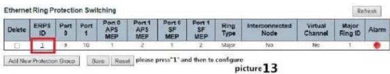
SW#1 ERPS configuration step 3 : as follow picture 14、picture 15

ERPS VLAN Configuration 1

SW#2 ERPS configuration step 1 : as follow picture 19
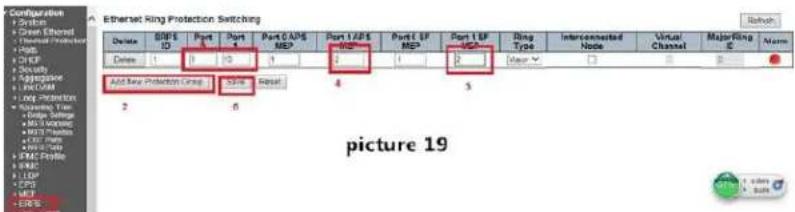
SW#2 ERPS configuration step 2: as follow picture 20.


ERPS VLAN Configuration 1

SW#3 ERPS configuration step 1: as follow picture 25

SW#3 ERPS configuration step 2: as follow picture 26

SW#3 ERPS configuration step 3 : as follow picture 27

Save the configuration:
When finished the configuration for each switch, should be saved. Otherwise, the device would default the set-up while it restarts.
SW#1 step 1 : as follow picture 16

5.3.12 NTP Setup
Appendix 4 NTP
Setup
Time/Date NTP Time Zone Settings
Step 1: Locate usable NTP servers
Suggested public addresses
158.69.48.97
216.218.245.202
66.228.42.59
216.239.35.0 (Google NTP)
8.8.8.8 (Google NTP)
Step 2: Ping to make certain your network is addressing the NTP server
![Command Prompt Microsoft Windows [Version 10.0-10M1.085] (c) Microsoft Corporation. All rights reserved. C:\Users\Adminping 158.69.48.97 Pinging 158.69.48.97 with 32 bytes of data: Reply from 158.69.48.97: bytes=32 time=90ms TTL=46 Reply from 158.69.48.97: bytes=32 time=80ms TTL=46 Reply from 158.69.48.97: bytes=32 time=88ms TTL=46 Reply from 158.69.48.97: bytes=32 time=89ms TTL=46 Ping statistics for 158.69.48.97: Packets: Sunt = A, Received = A, lost = 0 (0% loss), Approximate round trip times in milli-seconds: Minimum = 30ms, Maximum = 50ms, Average = 88ms C:\Users\Admino](/content/2026/06/1229384/images/fdeb86e110cda5336c5ffc90bf51dfb1f97c73e314451d85a13fb135de3da497.jpg)
Step 3: Configuration>IP Configuration
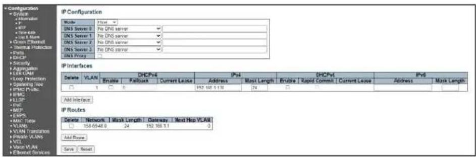
a. Confirm IPv4 shows the current Vi30210 IP address
- Confirm the mask length =24
- Confirm VLAN is associated as VLAN 1
b. IP routes
- Under Network enter the lowest IP address (.0) of the NTP Server network
- Enter the mask length =24
- Enter the Gateway address
- If need enter the number of the Next Hop VLAN
Step 4: Enter the NTP server IP address
Configuration>NTP Configuration
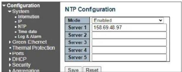
You can enter up to 5 servers
Save the setting
5.3.13 Appendix 5 Glossary
ACE
ACE is an acronym for Access Control Entry. It describes access permission associated with a particular ACE ID. There are three ACE frame types (Ethernet Type, ARP, and IPv4) and two ACE actions (permit and deny). The ACE also contains many detailed, different parameter options that are available for individual application.
ACL
ACL is an acronym for Access Control List. It is the list table of ACEs, containing access control entries that specify individual users or groups permitted or denied to specific traffic objects, such as a process or a program. Each accessible traffic object contains an identifier to its ACL. The privileges determine whether there are specific traffic object access rights. ACL implementations can be quite complex, for example, when the ACEs are prioritized for the various situation. In networking, the ACL refers to a list of service ports or network services that are available on a host or server, each with a list of hosts or servers permitted or denied to use the service. ACL can generally be configured to control inbound traffic, and in this context, they are similar to firewalls.
AES
AES is an acronym for Advanced Encryption Standard. The encryption key protocol is applied in 802.1i standard to improve WLAN security. It is an encryption standard by the U.S. government, which will replace DES and 3DES. AES has a fixed block size of 128 bits and a key size of 128, 192, or 256 bits.
AMS
AMS is an acronym for Auto Media Select. AMS is used for dual media ports (ports supporting both copper (cu) and fiber (SFP) cables. AMS automatically determines if a SFP or a CU cable is inserted and switches to the corresponding media. If both SFP and cu cables are inserted, the port will select the preferred media.
APS
APS is an acronym for Automatic Protection Switching. This protocol is used to secure that switching is done bidirectional in the two ends of a protection group, as defined in G.8031.
ARP
ARP is an acronym for Address Resolution Protocol. It is a protocol that used to convert an IP address into a physical address, such as an Ethernet address. ARP allows a host to communicate with other hosts when only the Internet address of its neighbors is known. Before using IP, the host sends a broadcast ARP request containing the Internet address of the desired destination system.
ARP Inspection
ARP Inspection is a secure feature. Several types of attacks can be launched against a host or devices connected to Layer 2 networks by "poisoning" the ARP caches. This feature is used to block such attacks. Only valid ARP requests and responses can go through the switch device.
CC
CC is an acronym for Continuity Check. It is a MEP functionality that is able to detect loss of continuity in a network by transmitting CCM frames to a peer MEP.
CCM
CCM is an acronym for Continuity Check Message. It is a OAM frame transmitted from a MEP to it's peer MEP and used to implement CC functionality.
CDP
CDP is an acronym for Cisco Discovery Protocol.
DEI
DEI is an acronym for Drop Eligible Indicator. It is a 1-bit field in the VLAN tag.
DES
DES is an acronym for Data Encryption Standard. It provides a complete description of a mathematical algorithm for encrypting (enciphering) and decrypting (deciphering) binary coded information.
DHCP
DHCP is an acronym for Dynamic Host Configuration Protocol. It is a protocol used for assigning dynamic IP addresses to devices on a network.
DHCP Relay
DHCP Relay is used to forward and to transfer DHCP messages between the clients and the server when they are not on the same subnet domain.
DHCP Snooping
DHCP Snooping is used to block intruder on the untrusted ports of the switch device when it tries to intervene by injecting a bogus DHCP reply packet to a legitimate conversation between the DHCP client and server.
DNS
DNS is an acronym for Domain Name System. It stores and associates many types of information with domain names. Most importantly, DNS translates human-friendly domain names and computer hostnames into computer-friendly IP addresses. For example, the domain name www.example.com might translate to 192.168.0.1.
DoS
DoS is an acronym for Denial of Service. In a denial-of-service (DoS) attack, an attacker attempts to prevent legitimate users from accessing information or services. By targeting at network sites or network connection, an attacker may be able to prevent network users from accessing email, web sites, online accounts (banking, etc.), or other services that rely on the affected computer.
DSCP
DSCP is an acronym for Differentiated Services Code Point. It is a field in the header of IP packets for packet classification purposes.
EEE
EEE is an abbreviation for Energy Efficient Ethernet defined in IEEE 802.3az.
EPS
EPS is an abbreviation for Ethernet Protection Switching defined in ITU/T G.8031.
Ethernet Type
Ethernet Type, or EtherType, is a field in the Ethernet MAC header, defined by the Ethernet networking standard. It is used to indicate which protocol is being transported in an Ethernet frame.
FTP
FTP is an acronym for File Transfer Protocol. It is a transfer protocol that uses the Transmission Control Protocol (TCP) and provides file writing and reading. It also provides directory service and security features.
Fast Leave
Multicast snooping Fast Leave processing allows the switch to remove an interface from the forwarding-table entry without first sending out group specific queries to the interface. The VLAN interface is pruned from the multicast tree for the multicast group specified in the original leave message. Fast-leave processing ensures optimal bandwidth management for all hosts on a switched network, even when multiple multicast groups are in use simultaneously. This processing applies to IGMP and MLD.
HTTP
HTTP is an acronym for Hypertext Transfer Protocol. It is a protocol that used to transfer or convey information on the World Wide Web (WWW). HTTP defines how messages are formatted and transmitted, and what actions Web servers and browsers should take in response to various commands. For example, when you enter a URL in your browser, this actually sends an HTTP command to the Web server directing it to fetch and transmit the requested
WEB
Web page. The other main standard that controls how the World Wide Web works is HTML, which covers how Web pages are formatted and displayed.
Any Web server machine contains, in addition to the Web page files it can serve, an HTTP daemon, a program that is designed to wait for HTTP requests and handle them when they arrive. The Web browser is an HTTP client, sending requests to server machines. An HTTP client initiates a request by establishing a Transmission Control Protocol (TCP) connection to a particular port on a remote host (port 80 by default). An HTTP server listening on that port waits for the client to send a request message.
HTTPS
HTTPS is an acronym for Hypertext Transfer Protocol over Secure Socket Layer. It is used to indicate a secure HTTP connection. HTTPS provide authentication and encrypted communication and is widely used on the World Wide Web for security-sensitive communication such as payment transactions and corporate logins. HTTPS is really just the use of Netscape's Secure Socket Layer (SSL) as a sublayer under its regular HTTP application layering. (HTTPS uses port 443 instead of HTTP port 80 in its interactions with the lower layer, TCP/IP.) SSL uses a 40-bit key size for the RC4 stream encryption algorithm, which is no longer considered an adequate degree of encryption for commercial exchange.
ICMP
ICMP is an acronym for Internet Control Message Protocol. It is a protocol that generated the error response, diagnostic or routing purposes. ICMP messages generally contain information about routing difficulties or simple exchanges such as time-stamp or echo transactions. For example, the PING command uses ICMP to test an Internet connection.
IEEE 802.1X
IEEE 802.1X is an IEEE standard for port-based Network Access Control. It provides authentication to devices attached to a LAN port, establishing a point-to-point connection or preventing access from that port if authentication fails. With 802.1X, access to all switch ports can be centrally controlled from a server, which means that authorized users can use the same credentials for authentication from any point within the network.
IGMP
IGMP is an acronym for Internet Group Management Protocol. It is a communications protocol used to manage the membership of Internet Protocol multicast groups. IGMP is used by IP hosts and adjacent multicast routers to establish multicast group memberships. It is an integral part of the IP multicast specification, like ICMP for unicast connections. IGMP can be used for online video and gaming, and allows more efficient use of resources when supporting these uses.
IGMP Querier
A router sends IGMP Query messages onto a particular link. This router is called the Querier. There will be only one IGMP Querier that wins Querier election on a particular link.
IMAP
IMAP is an acronym for Internet Message Access Protocol. It is a protocol for email clients to retrieve email messages from a mail server. IMAP is the protocol that IMAP clients use to communicate with the servers, and SMTP is the protocol used to transport mail to an IMAP server. The current version of the Internet Message Access Protocol is IMAP4. It is similar to Post Office Protocol version 3 (POP3), but offers additional and more complex features. For example, the IMAP4 protocol leaves your email messages on the server rather than downloading them to your computer. If you wish to remove your messages from the server, you must use your mail client to generate local folders, copy messages to your local hard drive, and then delete and expunge the messages from the server.
IP
IP is an acronym for Internet Protocol. It is a protocol used for communicating data across an internet network. IP is a "best effort" system, which means that no packet of information sent over is assured to reach its destination in the same condition it was sent. Each device connected to a Local Area Network (LAN) or Wide Area Network (WAN) is given an Internet Protocol address, and this IP address is used to identify the device uniquely among all other devices connected to the extended network. The current version of the Internet protocol is IPv4, which has 32-bits Internet Protocol addresses allowing for in excess of four billion unique addresses. This number is reduced drastically by the practice of webmasters taking addresses in large blocks, the bulk of which remain unused. There is a rather substantial movement to adopt a new
version of the Internet Protocol, IPv6, which would have 128-bits Internet Protocol addresses. This number can be represented roughly by a three with thirty-nine zeroes after it. However, IPv4 is still the protocol of choice for most of the Internet.
IPMC
IPMC is an acronym for IP MultiCast. IPMC supports IPv4 and IPv6 multicasting. IPMCv4 denotes multicast for IPv4. IPMCv6 denotes multicast for IPv6.
IPMC Profile
IPMC Profile is an acronym for IP MultiCast Profile. IPMC Profile is used to deploy the access control on IP multicast streams.
IP Source Guard
IP Source Guard is a secure feature used to restrict IP traffic on DHCP snooping untrusted ports by filtering traffic based on the DHCP Snooping Table or manually configured IP Source Bindings. It helps prevent IP spoofing attacks when a host tries to spoof and use the IP address of another host.
LACP
LACP is an IEEE 802.3ad standard protocol. The Link Aggregation Control Protocol, allows bundling several physical ports together to form a single logical port.
LLC
The IEEE 802.2 Logical Link Control (LLC) protocol provides a link mechanism for upper layer protocols. It is the upper sub-layer of the Data Link Layer and provides multiplexing mechanisms that make it possible for several network protocols (IP, IPX) to coexist within a multipoint network. LLC header consists of 1-byte DSAP (Destination Service Access Point), 1 byte SSAP (Source Service Access Point), 1 or 2 bytes Control field followed by LLC information.
LLDP
LLDP is an IEEE 802.1ab standard protocol. The Link Layer Discovery Protocol (LLDP) specified in this standard allows stations attached to an IEEE 802 LAN to advertise, to other stations attached to the same IEEE 802 LAN, the major capabilities provided by the system incorporating that station, the management address or addresses of the entity or entities that provide management of those capabilities, and the identification of the stations point of attachment to the IEEE 802 LAN required by those management entity or entities. The information distributed via this protocol is stored by its recipients in a standard Management Information Base (MIB), making it possible for the information to be accessed by a Network Management System (NMS) using a management protocol such as the Simple Network Management Protocol (SNMP).
LLDP-MED
LLDP-MED is an extension of IEEE 802.1ab and is defined by the telecommunication industry association (TIA-1057).
LLQI
LLQI (Last Listener Query Interval) is the maximum response time used to calculate the Maximum Response Code inserted into Specific Queries. It is used to detect the departure of the last listener for a multicast address or source. In IGMP, this term is called LMQI (Last Member Query Interval).
LOC
LOC is an acronym for Loss of Connectivity and is detected by a MEP and is indicating lost connectivity in the network. Can be used as switch criteria by EPS
MAC Table
Switching of frames is based upon the DMAC address contained in the frame. The switch builds up a table that maps MAC addresses to switch ports for knowing which ports the frames should go to (based upon the DMAC address in the frame). This table contains both static and dynamic entries. The static entries are configured by the network administrator if the administrator wants to do a fixed mapping between the DMAC address and switch ports.
The frames also contain a MAC address (SMAC address), which shows the MAC address of the equipment sending the frame. The SMAC address is used by the switch to automatically update the MAC table with these dynamic MAC
addresses. Dynamic entries are removed from the MAC table if no frame with the corresponding SMAC address have been seen after a configurable age time.
MEP
MEP is an acronym for Maintenance Entity Endpoint and is an endpoint in a Maintenance Entity Group (ITU-T Y.1731).
MD5
MD5 is an acronym for Message-Digest algorithm 5. MD5 is a message digest algorithm, used cryptographic hash function with a 128-bit hash value. It was designed by Ron Rivest in 1991. MD5 is officially defined in RFC 1321 - The MD5 Message-Digest Algorithm.
Mirroring
For debugging network problems or monitoring network traffic, the switch system can be configured to mirror frames from multiple ports to a mirror port. (In this context, mirroring a frame is the same as copying the frame.)
Both incoming (source) and outgoing (destination) frames can be mirrored to the mirror port.
MLD
MLD is an acronym for Multicast Listener Discovery for IPv6. MLD is used by IPv6 routers to discover multicast listeners on a directly attached link, much as IGMP is used in IPv4. The protocol is embedded in ICMPv6 instead of using a separate protocol.
MLD Querier
A router sends MLD Query messages onto a particular link. This router is called the Querier. There will be only one MLD Querier that wins Querier election on a particular link.
MSTP
In 2002, the IEEE introduced an evolution of RSTP: the Multiple Spanning Tree Protocol. The MSTP protocol provides for multiple spanning tree instances, while ensuring RSTP and STP compatibility. The standard was originally defined by IEEE 802.1s, but was later incorporated in IEEE 802.1D-2005.
MVR
Multicast VLAN Registration (MVR) is a protocol for Layer 2 (IP)-networks that enables multicast-traffic from a source VLAN to be shared with subscriber-VLANs.
The main reason for using MVR is to save bandwidth by preventing duplicate multicast streams being sent in the core network, instead the stream(s) are received on the MVR-VLAN and forwarded to the VLANs where hosts have requested it/them (Wikipedia).
NAS
NAS is an acronym for Network Access Server. The NAS is meant to act as a gateway to guard access to a protected source. A client connects to the NAS, and the NAS connects to another resource asking whether the client's supplied credentials are valid. Based on the answer, the NAS then allows or disallows access to the protected resource. An example of a NAS implementation is IEEE 802.1X.
NetBIOS
NetBIOS is an acronym for Network Basic Input/Output System. It is a program that allows applications on separate computers to communicate within a Local Area Network (LAN), and it is not supported on a Wide Area Network (WAN).
The NetBIOS giving each computer in the network both a NetBIOS name and an IP address corresponding to a different host name, provides the session and transport services described in the Open Systems Interconnection (OSI) model.
NFS
NFS is an acronym for Network File System. It allows hosts to mount partitions on a remote system and use them as though they are local file systems.
NFS allows the system administrator to store resources in a central location on the network, providing authorized users continuous access to them, which means NFS supports sharing of files, printers, and other resources as persistent storage over a computer network.
NTP
NTP is an acronym for Network Time Protocol, a network protocol for synchronizing the clocks of computer systems. NTP uses UDP (datagrams) as transport layer.
OAM
OAM is an acronym for Operation Administration and Maintenance.
It is a protocol described in ITU-T Y.1731 used to implement carrier Ethernet functionality. MEP functionality like CC and RDI is based on this.
Optional TLVs.
A LLDP frame contains multiple TLVs. For some TLVs it is configurable if the switch shall include the TLV in the LLDP frame. These TLVs are known as optional TLVs. If an optional TLVs is disabled the corresponding information is not included in the LLDP frame.
OUI
OUI is the organizationally unique identifier. An OUI address is a globally unique identifier assigned to a vendor by IEEE. You can determine which vendor a device belongs to according to the OUI address which forms the first 24 bits of a MAC address.
PCP
PCP is an acronym for Priority Code Point. It is a 3-bit field storing the priority level for the 802.1Q frame. It is also known as User Priority.
PD
PD is an acronym for Powered Device. In a PoE system the power is delivered from a PSE (power sourcing equipment) to a remote device. The remote device is called a PD.
PHY
PHY is an abbreviation for Physical Interface Transceiver and is the device that implements the Ethernet physical layer (IEEE-802.3).
PING
Ping (Packet InterNet Grouper) is a program that sends a series of packets over a network or the Internet to a specific computer in order to generate a response from that computer. The other computer responds with an acknowledgment that it received the packets. Ping was created to verify whether a specific computer on a network or the Internet exists and is connected. Ping uses Internet Control Message Protocol (ICMP) packets. The PING Request is the packet from the origin computer, and the PING Reply is the packet response from the target.
PoE
PoE is an acronym for Power Over Ethernet. Power over Ethernet is used to transmit electrical power, to remote devices over standard Ethernet cable. It could for example be used for powering IP telephones, wireless LAN Access Points (AP), IP cameras and other equipment, where it would be difficult or expensive to connect the equipment to main power supply.
Policer
A policer can limit the bandwidth of received frames. It is located in front of the ingress queue.
POP3
POP3 is an acronym for Post Office Protocol version 3. It is a protocol for email clients to retrieve email messages from a mail server.
POP3 is designed to delete mail on the server as soon as the user has downloaded it. However, some implementations allow users or an administrator to specify that mail be saved for some period of time. POP can be thought of as a "store-and-forward" service. An alternative protocol is Internet Message Access Protocol (IMAP). IMAP provides the user with more capabilities for retaining e-mail on the server and for organizing it in folders on the server. IMAP can be thought of as a remote file server.
POP and IMAP deal with the receiving of e-mail and are not to be confused with the Simple Mail Transfer Protocol (SMTP). You send e-mail with SMTP, and a mail handler receives it on your recipient's behalf. Then the mail is read using POP or IMAP. IMAP4 and POP3 are the two most prevalent Internet standard protocols for e-mail retrieval. Virtually all modern e-mail clients and servers support both.
PPPoE
PPPoE is an acronym for Point-to-Point Protocol over Ethernet. It is a network protocol for encapsulating Point-to-Point Protocol (PPP) frames inside Ethernet frames. It is used mainly with ADSL services where individual users connect to the ADSL transceiver (modem) over Ethernet and in plain Metro Ethernet networks (Wikipedia).
Private VLAN
In a private VLAN, PVLANs provide layer 2 isolation between ports within the same broadcast domain. Isolated ports configured as part of PVLAN cannot communicate with each other. Member ports of a PVLAN can communicate with each other.
PTP
PTP is an acronym for Precision Time Protocol, a network protocol for synchronizing the clocks of computer systems.
QCE
QCE is an acronym for QoS Control Entry. It describes QoS class associated with a particular QCE ID. There are six QCE frame types: Ethernet Type, VLAN, UDP/TCP Port, DSCP, TOS, and Tag Priority. Frames can be classified by one of 4 different QoS classes: "Low", "Normal", "Medium", and "High" for individual application.
QCI
QCI is an acronym for QoS Class Identifier. This is a special identifier defining the quality of packet communication provided by LTE (Long Term Evolution, marketed as 4G LTE).
QCL
QCL is an acronym for QoS Control List. It is the list table of QCEs, containing QoS control entries that classify to a specific QoS class on specific traffic objects.
Each accessible traffic object contains an identifier to its QCL. The privileges determine specific traffic object to specific QoS class.
QL
QL In SyncE this is the Quality Level of a given clock source. This is received on a port in a SSM indicating the quality of the clock received in the port.
QoS
QoS is an acronym for Quality of Service. It is a method to guarantee a bandwidth relationship between individual applications or protocols.
A communications network transports a multitude of applications and data, including high-quality video and delay-sensitive data such as real-time voice. Networks must provide secure, predictable, measurable, and sometimes guaranteed services.
Achieving the required QoS becomes the secret to a successful end-to-end business solution.
Therefore, QoS is the set of techniques to manage network resources.
QoS class
Every incoming frame is classified to a QoS class, which is used throughout the device for providing queuing, scheduling and congestion control guarantees to the frame according to what was configured for that specific QoS class. There is a one-to-one mapping between QoS class, queue and priority. A QoS class of 0 (zero) has the lowest priority.
Querier Election
Querier election is used to dedicate the Querier, the only one router sends Query messages, on a particular link. Querier election rule defines that IGMP Querier or MLD Querier with the lowest IPv4/IPv6 address wins the election.
RARP
RARP is an acronym for Reverse Address Resolution Protocol. It is a protocol that is used to obtain an IP address for a given hardware address, such as an Ethernet address. RARP is the complement of ARP.
RADIUS
RADIUS is an acronym for Remote Authentication Dial in User Service. It is a networking protocol that provides centralized access, authorization and accounting management for people or computers to connect and use a network service.
RDI
RDI is an acronym for Remote Defect Indication. It is a OAM functionality that is used by a MEP to indicate defect detected to the remote peer MEP.
Router Port
A router port is a port on the Ethernet switch that leads switch towards the Layer 3 multicast device.
RSTP
In 1998, the IEEE with document 802.1w introduced an evolution of STP: the Rapid Spanning Tree Protocol, which provides for faster spanning tree convergence after a topology change. Standard IEEE 802.1D-2004 now incorporates RSTP and obsoletes STP, while at the same time being backwards-compatible with STP.
SAMBA
Samba is a program running under UNIX-like operating systems (not the Brazilian dance) that provides seamless integration between UNIX and Microsoft Windows machines. Samba acts as file and print servers for Microsoft Windows, IBM OS/2, and other SMB client machines. Samba uses the Server Message Block (SMB) protocol and Common Internet File System (CIFS), which is the underlying protocol used in Microsoft Windows networking.
Samba can be installed on a variety of operating system platforms, including Linux, most common Unix platforms, OpenVMS, and IBM OS/2.
Samba can also register itself with the master browser on the network so that it would appear in the listing of hosts in Microsoft Windows "Neighborhood Network".
sFlow
sFlow is an industry standard technology for monitoring switched networks through random sampling of packets on switch ports and time-based sampling of port counters. The sampled packets and counters (referred to as flow samples and counter samples, respectively) are sent as sFlow UDP datagrams to a central network traffic monitoring server. This central server is called an sFlow receiver or sFlow collector.
Additional information can be found at http://sflow.org.
SHA
SHA is an acronym for Secure Hash Algorithm. It designed by the National Security Agency (NSA) and published by the NIST as a U.S. Federal Information Processing Standard. Hash algorithms compute a fixed-length digital representation (known as a message digest) of an input data sequence (the message) of any length.
Shaper
A shaper can limit the bandwidth of transmitted frames. It is located after the ingress queues.
SMTP
SMTP is an acronym for Simple Mail Transfer Protocol. It is a text-based protocol that uses the Transmission Control Protocol (TCP) and provides a mail service modeled on the FTP file transfer service. SMTP transfers mail messages between systems and notifications regarding incoming mail.
The SubNetwork Access Protocol (SNAP) is a mechanism for multiplexing, on networks using IEEE 802.2 LLC, more protocols than can be distinguished by the 8-bit 802.2 Service Access Point (SAP) fields. SNAP supports identifying protocols by Ethernet type field values; it also supports vendor-private protocol identifier.
SNMP
SNMP is an acronym for Simple Network Management Protocol. It is part of the Transmission Control Protocol/Internet Protocol (TCP/IP) protocol for network management. SNMP allow diverse network objects to participate in a network management architecture. It enables network management systems to learn network problems by receiving traps or change notices from network devices implementing SNMP.
SNTP
SNTP is an acronym for Simple Network Time Protocol, a network protocol for synchronizing the clocks of computer systems. SNTP uses UDP (datagrams) as transport layer.
SPROUT
Stack Protocol using ROUting Technology. An advanced protocol for almost instantaneous discovery of topology changes within a stack as well as election of a master switch. SPROUT also calculates parameters for setting up each switch to perform shortest path forwarding within the stack.
SSID
Service Set Identifier is a name used to identify the particular 802.11 wireless LANs to which a user wants to attach. A client device will receive broadcast messages from all access points within range advertising their SSIDs, and can choose one to connect to based on pre-configuration, or by displaying a list of SSIDs in range and asking the user to select one (wikipedia).
SSH
SSH is an acronym for Secure SHell. It is a network protocol that allows data to be exchanged using a secure channel between two networked devices. The encryption used by SSH provides confidentiality and integrity of data over an insecure network. The goal of SSH was to replace the earlier rlogin, TELNET and rsh protocols, which did not provide strong authentication or guarantee confidentiality (Wikipedia).
SSM
SSM In SyncE this is an abbreviation for Synchronization Status Message and is containing a QL indication.
STP
Spanning Tree Protocol is an OSI layer-2 protocol which ensures a loop free topology for any bridged LAN. The original STP protocol is now obsolete by RSTP.
Switch ID
Switch IDs (1-1) are used to uniquely identify the switches within a stack. The Switch ID of each switch is shown on the display on the front of the switch and is used widely in the web pages as well as in the CLI commands.
SyncE
SyncE Is an abbreviation for Synchronous Ethernet. This functionality is used to make a network 'clock frequency' synchronized. Not to be confused with real time clock synchronized (IEEE 1588).
TACACS+
TACACS+ is an acronym for Terminal Access Controller Access Control System Plus. It is a networking protocol which provides access control for routers, network access servers and other networked computing devices via one or more centralized servers. TACACS+ provides separate authentication, authorization and accounting services.
Tag Priority
Tag Priority is a 3-bit field storing the priority level for the 802.1Q frame. The 3-bits provide 8 priority levels (0\~7).
TCP
TCP is an acronym for Transmission Control Protocol. It is a communications protocol that uses the Internet Protocol (IP) to exchange the messages between computers.
The TCP protocol guarantees reliable and in-order delivery of data from sender to receiver and distinguishes data for multiple connections by concurrent applications (for example, Web server and e-mail server) running on the same host.
The applications on networked hosts can use TCP to create connections to one another. It is known as a connection-oriented protocol, which means that a connection is established and maintained until such time as the message or messages to be exchanged by the application programs at each end have been exchanged. TCP is responsible for ensuring that a message is divided into the packets that IP manages and for reassembling the packets back into the complete message at the other end. Common network applications that use TCP include the World Wide Web (WWW), e-mail, and File Transfer Protocol (FTP).
TELNET
TELNET is an acronym for TELetype NETwork. It is a terminal emulation protocol that uses the Transmission Control Protocol (TCP) and provides a virtual connection between TELNET server and TELNET client.
TELNET enables the client to control the server and communicate with other servers on the network. To start a Telnet session, the client user must log in to a server by entering a valid username and password. Then, the client user can enter commands through the Telnet program just as if they were entering commands directly on the server console.
TFTP
TFTP is an acronym for Trivial File Transfer Protocol. It is transfer protocol that uses the User Datagram Protocol (UDP) and provides file writing and reading, but it does not provide directory service and security features.
ToS
ToS is an acronym for Type of Service. It is implemented as the IPv4 ToS priority control. It is fully decoded to determine the priority from the 6-bit ToS field in the IP header. The most significant 6 bits of the ToS field are fully decoded into 64 possibilities, and the singular code that results is compared against the corresponding bit in the IPv4 ToS priority control bit (0\~63).
TLV
TLV is an acronym for Type Length Value. A LLDP frame can contain multiple pieces of information. Each of these pieces of information is known as TLV.
TKIP
TKIP is an acronym for Temporal Key Integrity Protocol. It used in WPA to replace WEP with a new encryption algorithm. TKIP comprises the same encryption engine and RC4 algorithm defined for WEP. The key used for encryption in TKIP is 128 bits and changes the key used for each packet.
UDP
UDP is an acronym for User Datagram Protocol. It is a communications protocol that uses the Internet Protocol (IP) to exchange the messages between computers.
UDP is an alternative to the Transmission Control Protocol (TCP) that uses the Internet Protocol (IP). Unlike TCP, UDP does not provide the service of dividing a message into packet datagrams, and UDP doesn't provide reassembling and sequencing of the packets. This means that the application program that uses UDP must be able to make sure that the entire message has arrived and is in the right order. Network applications that want to save processing time because they have very small data units to exchange may prefer UDP to TCP.
UDP provides two services not provided by the IP layer. It provides port numbers to help distinguish different user requests and, optionally, a checksum capability to verify that the data arrived intact.
Common network applications that use UDP include the Domain Name System (DNS), streaming media applications such as IPTV, Voice over IP (VoIP), and Trivial File Transfer Protocol (TFTP).
UPnP
UPnP is an acronym for Universal Plug and Play. The goals of UPnP are to allow devices to connect seamlessly and to simplify the implementation of networks in the home (data sharing, communications, and entertainment) and in corporate environments for simplified installation of computer components.
User Priority is a 3-bit field storing the priority level for the 802.1Q frame. It is also known as PCP.
VLAN
Virtual LAN.A method to restrict communication between switch ports. VLANs can be used for the following applications:
VLAN unaware switching: This is the default configuration. All ports are VLAN unaware with Port VLAN ID 1 and members of VLAN 1. This means that MAC addresses are learned in VLAN 1, and the switch does not remove or insert VLAN tags.
VLAN aware switching: This is based on the IEEE 802.1Q standard. All ports are VLAN aware. Ports connected to VLAN aware switches are members of multiple VLANs and transmit tagged frames. Other ports are members of one VLAN, set up with this Port VLAN ID, and transmit untagged frames. Provider switching: This is also known as Q-in-Q switching. Ports connected to subscribers are VLAN unaware, members of one VLAN, and set up with this unique Port VLAN ID. Ports connected to the service provider are VLAN aware, members of multiple VLANs, and set up to tag all frames. Untagged frames received on a subscriber port are forwarded to the provider port with a single VLAN tag. Tagged frames received on a subscriber port are forwarded to the provider port with a double VLAN tag.
VLAN ID
VLAN ID is a 12-bit field specifying the VLAN to which the frame belongs.
Voice VLAN
Voice VLAN is VLAN configured specially for voice traffic. By adding the ports with voice devices attached to voice VLAN, we can perform QoS-related configuration for voice data, ensuring the transmission priority of voice traffic and voice quality.
WEP
WEP is an acronym for Wired Equivalent Privacy. WEP is a deprecated algorithm to secure IEEE 802.11 wireless networks. Wireless networks broadcast messages using radio, and are more susceptible to eavesdropping than wired networks. When introduced in 1999, WEP was intended to provide confidentiality comparable to that of a traditional wired network (Wikipedia).
WiFi
WiFi is an acronym for Wireless Fidelity. It is meant to be used generically when referring of any type of 802.11 network, whether 802.11b, 802.11a, dual-band, etc. The term is promulgated by the Wi-Fi Alliance.
WPA
WPA is an acronym for Wi-Fi Protected Access. It was created in response to several serious weaknesses researchers had found in the previous system, Wired Equivalent Privacy (WEP). WPA implements the majority of the IEEE 802.11i standard, and was intended as an intermediate measure to take the place of WEP while 802.11i was prepared. WPA is specifically designed to also work with pre-WPA wireless network interface cards (through firmware upgrades), but not necessarily with first generation wireless access points. WPA2 implements the full standard, but will not work with some older network cards (Wikipedia).
WPA-PSK
WPA-PSK is an acronym for Wi-Fi Protected Access - Pre-Shared Key. WPA was designed to enhance the security of wireless networks. There are two flavors of WPA: enterprise and personal. Enterprise is meant for use with an IEEE 802.1X authentication server, which distributes different keys to each user. Personal WPA utilizes less scalable 'pre-shared key' (PSK) mode, where every allowed computer is given the same passphrase. In PSK mode, security depends on the strength and secrecy of the passphrase. The design of WPA is based on a Draft 3 of the IEEE 802.11i standard (Wikipedia)
WPA-Radius
WPA-Radius is an acronym for Wi-Fi Protected Access - Radius (802.1X authentication server). WPA was designed to enhance the security of wireless networks. There are two flavors of WPA: enterprise and personal. Enterprise is meant for use with an IEEE 802.1X authentication server, which distributes different keys to each user. Personal WPA utilizes less scalable 'pre-shared key' (PSK) mode, where every allowed computer is given the same passphrase. In PSK mode
security depends on the strength and secrecy of the passphrase. The design of WPA is based on a Draft 3 of the IEEE 802.11i standard (Wikipedia).
WPS
WPS is an acronym for Wi-Fi Protected Setup. It is a standard for easy and secure establishment of a wireless home network. The goal of the WPS protocol is to simplify the process of connecting any home device to the wireless network (Wikipedia).
WRED
WRED is an acronym for Weighted Random Early Detection. It is an active queue management mechanism that provides preferential treatment of higher priority frames when traffic builds up within a queue. A frame's DP level is used as input to WRED. A higher DP level assigned to a frame results in a higher probability that the frame is dropped during times of congestion.
WTR
WTR is an acronym for Wait To Restore. This is the time a fail on a resource has to be 'not active' before restoration back to this (previously failing) resource is done.

- MaxiiNet™ Vi30210 Operation and Installation Manual
- Purpose
- Audience
- Conventions
- Warranty
- Disclaimer
- FCC
- FCC Caution
- Compliances and Safety Statements
- FCC - Class
- CE Mark Declaration of Conformance for EMI and Safety (EEC)
- EMC- Compliance
- Add an arrester between the outdoor device and this switch
- Introduction
- Overview
- Table of Contents
- Security 64
- Aggregation....93
- Link OAM 96
- Loop Protections 98
- Spanning Tree 99
- IOMC Profile....104
- IPMC 105
- LLDP 112
- PoE....117
- MEP 119
- ERPS 120
- MAC Table....121
- VLAN Translation....126
- VLAN Translation Mappings 127
- Private VLAN 128
- VCL....129
- Voice VLAN....132
- Ethernet Services 135
- QoS 142
- Mirroring....153
- UPnP 155
- GVRP 156
- sFlow....157
- Chapter 3: Monitor....158
- System 159
- Green Ethernet....162
- Ports 163
- Link OAM 165
- DHCP....167
- Security 169
- Aggregation....172
- Loop Protection....173
- Spanning Tree 174
- IPMC - IGMP 176
- LLDP 177
- Ethernet Services 178
- VLANs 179
- sFlow....180
- UDLD....181
- Chapter 4: Diagnostic ....182
- Chapter 5: Maintenance ....184
- Software 185
- Configuration 186
- Description of Hardware
- Network Planning
- Introduction to Switching
- Application Examples
- Installing the Switch
- Selecting a Site
- The site should:
- Ethernet Cabling
- Equipment Checklist
- Package Contents
- i
- DIN Rail Mounting
- Wall Mounting and Desktop Mounting
- NOTE:
- CAUTION:
- Description
- Connecting to the Console Port
- RJ-45pin Assignment
- Making Network Connections
- Connecting Network Devices
- Cabling Guidelines- UTP Copper Cabling
- Connectivity Rules
- Cable Labeling and Connection Records
- Basic Troubleshooting Tips
- Power and Cooling Problems
- Installation
- Cables
- 10BASE-T/100Base-Tx Pin Assignments
- Fiber Standards
- Specifications
- Physical Characteristics
- Switch Features
- Management Features
- Standards
- Emissions
- Immunity
- Compliances
- Contact Information
- GUI Header Controls
- WEB Configuration
- Chapter 1: Configuration Preparation
- Access to Switch by WEB
- Reset key – default function:
- Guide
- Top Control
- Auto-refresh □ Refresh
- Chapter 2: Monitor
- System
- Information Configuration
- System Information State
- IP
- Devise IP Configuration
- NTP
- Time
- Log & Alarm
- System Log
- System Log Configuration
- System Alarm Configuration
- Green Ethernet
- LED
- LED Power Reduction Configuration
- Port Power Savings
- Port Power Savings Configuration
- Port Power Saving Configuration Dialog
- Thermal Protection
- Thermal Protection
- Ports
- Ports Configuration
- Port Configuration
- DHCP
- DHCP Server Mode Configuration
- Global Mode
- VLAN Mode
- DHCP Sever Mode Configuration
- Excluded IP
- DHCP Server Excluded IP Configuration
- Excluded IP Address
- Pool
- DHCP Server Pool Configuration
- DHCP Pool Configuration
- Snooping
- DHCP Snooping Configuration
- Port Mode Configuration
- Relay
- Relay Configuration Dialog
- Relay Mode
- Relay Server
- Relay Information Mode
- Relay Information Policy
- Security
- Security
- Switch
- Users
- Users Configuration 1
- Users Configuration 2
- Users Configuration
- Add User
- Privilege Level
- Privilege Registration Dialog
- Auth Method
- Auth Method Dialog
- Authentication Method Configuration:
- Command Authorization Method Configuration:
- Accounting Method Configuration:
- HTTPS Configuration
- Certificate Maintain
- Access Management Configuration
- Mode
- Version
- Read Community
- Write Community
- Engine ID
- Trap
- Trap Configuration
- SNMP Trap Configuration
- SNMP Trap Event
- Community Configuration
- Users
- SNMP User Configuration 1
- SNMP User Configuration 2
- Delete
- User Name
- Authentication Protocol
- Authentication Password
- Privacy Protocol
- Privacy Password
- SNMPv3 Configuration
- Security Name
- Group Name
- SNMPv3 View Configuration
- View Type
- OID Subtree
- SNMPv3 Access Configuration
- Security Model
- Security Level
- RMON
- Statistics
- Read View Name
- Write View Name
- RMON Statistics Configuration
- History
- Alarm
- RMON Alarm Configuration
- Event
- Picture 40: RMON Event Configuration
- Network Security
- Limit Control
- Port Security Limit Control Configuration
- System Configuration
- Reauthentication Enabled
- Reauthentication Period
- EAPOL Timeout
- Aging Period
- Hold Time
- RADIUS-Assigned QoS Enabled
- RADIUS-Assigned VLAN Enabled
- Guest VLAN Enabled
- Guest VLAN ID
- Max. Reauth. Count
- Allow Guest VLAN if EAPOL Seen
- Port
- Admin State
- RADIUS attributes used in identifying a VLAN ID:
- Guest VLAN Operation:
- Port State
- Restart
- ACL
- Ports
- Policy ID
- Action
- Rate Limiter ID
- EVC Policer
- EVC Policer ID
- Mirror
- Logging
- Shutdown
- State
- Counter
- Access
- Control List
- Access Control List Configuration
- ACE Configuration
- VLAN Parameters
- 2.6.2.4.1
- Configuration
- IP Source Guard Configuration
- Static Table
- Static IP Source Guard Table
- ARP Inspection Configuration
- VLAN
- VLAN Mode Configuration
- Static Table
- Static ARP Inspection Table
- AAA
- RADIUS
- RADIUS Server Configuration
- Timeout
- Retransmit
- Deadtime
- Key
- NAS-IP-Address (Attribute 4)
- NAS-IPv6-Address (Attribute 95)
- NAS-Identifier (Attribute 32)
- Hostname
- Auth Port
- Acct Port
- TACACS+
- TACACS+ Server Configuration
- Global Configuration
- Server Configuration
- Aggregation
- Aggregation
- Static
- Aggregation Mode Configuration
- Aggregation Group Configuration
- Source MAC Address
- Destination MAC Address
- IP Address
- TCP/UDP Port Number
- Group ID
- Port Members
- LACP
- LACP Enabled
- Role
- Prio
- Link OAM
- Port Settings
- OAM Enabled
- OAM Mode
- Loopback Support
- Link Monitor Support
- MIB Retrieval Support
- Loopback Operation
- Event Settings
- Event Name
- Error Window
- Error Threshold
- Loop Protections
- Loop Protection
- Ring protection configuration
- Spanning Tree
- Spanning Tree
- Bridge Settings
- Protocol Version
- Bridge Priority
- Hello Time
- Forward Delay
- Max Age
- Maximum Hop Count
- Transmit Hold Count
- Advanced Settings
- Edge Port BPDU Filtering
- Port Error Recovery
- Port Error Recovery Timeout
- MSTI Mapping
- Configuration Identification
- Configuration Name
- Configuration Revision
- MSTI
- VLANs Mapped
- MSTI Priorities
- Priority
- CIST Ports
- STP Enabled
- Path Cost
- operEdge (state flag)
- AdminEdge
- AutoEdge
- Restricted Role
- Restricted TCN
- BPDU Guard
- Point-to-Point
- IOMC Profile
- IPMC Profile
- Profile Table
- IPMC Profile Configurations
- IPMC Profile Table Setting
- Address Entry
- IPMC Profile Address Configuration
- IPMC
- IPMC
- IGMP Snooping
- Basic Configuration
- Snooping Enabled
- Unregistered IPMCv4 Flooding Enabled
- IGMP SSM Range
- Leave Proxy Enabled
- Proxy Enabled
- Router Port
- Fast Leave
- Throttling
- VLAN ID
- IGMP Snooping Enabled
- Querier Election
- Querier Address
- Compatibility
- PRI
- RV
- QI
- QRI
- LLQI (LMQI for IGMP)
- URI
- Port Filtering Profile
- MLD Snooping
- Unregistered IPMCv6 Flooding Enabled
- MLD SSM Range
- VLAN Configuration
- MLD Snooping Enabled
- LLQI
- Port Filtering Profile
- LLDP
- LLDP
- LLDP Configuration
- Tx Interval
- Tx Hold
- Tx Delay
- Tx Reinit
- Interface
- CDP Aware
- Port Descr
- Sys Name
- Sys Descr
- Sys Capa
- Mgmt Addr
- LLDP-MED Configuration
- - Coordinates Location
- • Civic Address Location
- - Policies
- MEP
- MEP
- ERPS
- ERPS
- MAC Table
- MAC Table Configuration
- MAC Address Table Configuration
- Allowed Access VLANs
- Ethertype for Custom S-ports
- Access:
- Trunk:
- Hybrid:
- Port VLAN
- Port Type
- Unaware:
- C-Port:
- S-Port:
- Notice:
- S-Custom-Port:
- VLAN Translation
- VLAN Translation
- Port to Group Configuration
- VLAN Translation Mappings
- VLAN
- Translation Mappings
- Private VLAN
- Private VLAN
- Membership
- port Isolation
- 2.21.2
- Protocol to Group
- Protocol to Group Mapping Table
- Group to VLAN
- Group Name to VLAN mapping Table
- IP
- Subnet-based VLAN
- IP Subnet-based VLAN Membership Configuration
- Voice VLAN
- Voice VLAN
- Configuration
- Aging Time
- Traffic Class
- Port Mode
- Port Security
- Port Discovery Protocol
- Telephony OUI
- Ethernet Services
- Ethernet Services
- Ports
- DEI Mode
- Tag Mode
- Address Mode
- DMAC
- L2CP Mode
- Bandwidth Profiles
- Start Policer ID
- Policer ID
- Type
- Policer Mode
- Rate Type
- CIR
- CBS
- EIR
- EBS
- EVC Configuration
- EVC ID
- Name
- VID
- IVID
- Learning
- Inner Tag Type
- Inner VID Mode
- Inner Tag VID
- Inner Tag PCP
- Inner Tag DEI
- Outer Tag VID
- NNI Ports
- ECE Configuration
- UNI Ports
- ECE ID
- Tag Type
- PCP
- DEI
- Frame Type
- Direction
- Tag Pop Count
- Class
- Outer Tag Mode
- Outer Tag PCP/DEI Preservation
- Outer Tag PCP
- Outer Tag DEI
- Conflict
- QoS
- QoS
- Port Classification
- CoS
- DPL
- Tag Class.
- DSCP Based
- Port Policing
- Enable
- Rate
- Unit
- Flow Control
- Queue Policing
- Port Scheduler
- Scheduler Mode
- Queue Shaper Enable
- Queue Shaper Rate
- Queue Shaper Unit
- Queue Shaper Excess
- Queue Scheduler Weight
- Queue Scheduler Percent
- Port Shaper Enable
- Port Shaper Rate
- Port Shaper Unit
- Port Shaping
- Port Tag Remarking
- Port DSCP
- Translate
- Classify
- Egress
- DSCP
- Trust
- QoS Class
- Ingress
- DSCP DPO
- DSCP DP1
- QCE
- SMAC
- Mirroring
- Mirroring
- Source
- Intermediate
- Destination
- UPnP
- UPnP
- UPnP Configuration
- TTL
- Advertising Duration
- GVRP
- GVRP
- Global Config
- Port Config
- sFlow
- UDLD
- UDLD Mode
- Message Interval
- Chapter 3: Monitor
- Monitor
- System
- System Information
- CPU Load
- IP Interfaces/IP Status
- Address
- Status
- Network
- Gateway
- Link Address
- System Information log
- Detailed System Log Information
- Green Ethernet
- Green Ethernet > Port Power Savings
- Local Port
- Link
- EEE cap
- EEE Ena
- LP EEE cap
- EEE In power save
- Actiphy Savings
- Thermal Protection Status
- Thermal Protection Status
- Ports
- Ports
- State
- QoS Statistics
- Queuing Counters
- QCL Status
- Detailed Port Statistics
- Link OAM (Operations-Administration-Maintenance)
- Detailed Link OAM Statistics for Port
- Rx and Tx OAM Information PDU's
- Rx and Tx Unique Error Event Notification
- Rx and Tx Duplicate Error Event Notification
- Rx and Tx Loopback Control
- Rx and Tx Variable Request
- Rx and Tx Variable Response
- Rx and Tx Org Specific PDU's
- Rx and Tx Unsupported Codes
- Rx and Tx Link fault PDU's
- Rx and Tx Dying Gasp
- Rx and Tx Critical Event PDU's
- Detailed Link OAM Status for Port
- Detailed Link OAM Link Status for Port
- DHCP
- DHCP Server
- DHCP Server Statistics
- DHCP Server Statistics
- DHCP Server Binding IP
- DHCP Server Declined IP
- DHCP Server Declined IP
- Dynamic DHCP Snooping Table
- DHCP Relay Statistics
- DHCP Detailed Statistics by Port
- Security
- Access Management Statistics
- Network
- Port Security
- Port Security Switch Status
- Port Security – Individual port status
- NAS
- Network Access Server Switch Status
- Individual NAS Statistics
- NAS Statistics Port 1
- ACL Status
- ARP Inspection
- Dynamic IP Source Guard Table
- Dynamic IP Source Guard Table
- Aggregation
- Aggregation Status
- LACP
- LACP System Status
- LACP Status
- LACP Statics
- Loop Protection
- Loop Protection Status
- Spanning Tree
- STP Bridge Status
- STI
- Bridge ID
- Root ID
- Root Port
- Root Cost
- Topology Flag
- Topology Change Last
- STP Port Status
- IPMC - IGMP
- IPMC
- IGMP Snooping
- IGMP Snooping Status
- IGMP Snooping Group Information
- IGMP SFM Information
- LLDP
- LLDP
- LLDP Neighbor Information
- LLDP MED Neighbor Information
- LLDP-MED Neighbor Information
- LLDP Neighbors EEE Information
- LLDP Global Counters
- Ethernet Services
- EVC Statistics
- PoE: Power Over Ethernet Status
- MAC Address Table
- VLAN Membership Status for Combined users
- VLANs
- VLAN
- sFlow Statistics
- sFlow Statistics
- UDLD
- UDLD
- Chapter 4: Diagnostic
- Diagnostic
- Diagnostics
- Ping
- ICMP Ping
- Link OAM
- MIB Retrieval
- Link OAM MIB Retrieval
- Chapter 5: Maintenance
- Maintenance
- Restart Device
- Restart Device
- Factory Defaults
- Factory Defaults
- Software
- Software
- Upload
- Software Upload
- Image Select
- Software Image Selection
- Configuration
- Save Running Configuration to startup-config
- Save startup-config
- Download
- Download Configuration
- Upload Configuration
- Upload Configuration
- File To Upload
- Destination File
- Activate
- Activate Configuration
- Delete
- Delete Configuration File
- Chapter Five Appendix
- Appendix1 Modify the device IP address
- Appendix2 VLAN Configuration
- Appendix3 ERPS configuration
- ERPS Monocyclic configuration
- VLANS Configuration
- IP Address Configuration:
- STP Configuration
- STP Configuration:
- MEP configuration
- ERPS Configuration
- Save the configuration:
- NTP Setup
- Appendix 5 Glossary
- ACE
- ACL
- AES
- AMS
- APS
- ARP
- ARP Inspection
- CC
- CCM
- CDP
- DES
- DHCP Relay
- DHCP Snooping
- DNS
- DoS
- EEE
- EPS
- Ethernet Type
- FTP
- HTTP
- WEB
- HTTPS
- ICMP
- IEEE 802.1X
- IGMP
- IGMP Querier
- IMAP
- IP
- IPMC Profile
- LACP
- LLC
- LLDP-MED
- LOC
- MAC Table
- MD5
- MLD
- MLD Querier
- MSTP
- MVR
- NAS
- NetBIOS
- NFS
- NTP
- OAM
- Optional TLVs.
- OUI
- PD
- PHY
- PING
- PoE
- Policer
- POP3
- PPPoE
- PTP
- QCI
- QCL
- QL
- RARP
- RADIUS
- RDI
- RSTP
- SAMBA
- sFlow
- SHA
- Shaper
- SMTP
- SNMP
- SNTP
- SPROUT
- SSID
- SSH
- SSM
- STP
- Switch ID
- SyncE
- TACACS+
- Tag Priority
- TCP
- TELNET
- TFTP
- ToS
- TLV
- TKIP
- UDP
- VLAN
- WEP
- WiFi
- WPA
- WPA-PSK
- WPA-Radius
- WPS
- WRED
- WTR
Brand : Vigitron
Model : Vi30210
Category : NAS