JX827FMDS - Microwaves GE - Free user manual and instructions
Find the device manual for free JX827FMDS GE in PDF.

User questions about JX827FMDS GE
0 question about this device. Answer the ones you know or ask your own.
Ask a new question about this device
Download the instructions for your Microwaves in PDF format for free! Find your manual JX827FMDS - GE and take your electronic device back in hand. On this page are published all the documents necessary for the use of your device. JX827FMDS by GE.
USER MANUAL JX827FMDS GE
Installation Instructions
Microwave Oven Built-In Trim Kits
JX827 and JX830
Questions? Call GE Appliances Answer Center at 800.626.2000 or Visit our Website at: GEAppliances.com
BEFORE YOU BEGIN
Read these instructions completely and carefully.
- IMPORTANT — Save these instructions for local inspector's use.
- IMPORTANT — Observe all governing codes and ordinances.
- Note to Installer – Be sure to leave these instructions with the Consumer.
- Note to Consumer – Keep these instructions for future reference.
- Skill level – Installation of this appliance requires basic mechanical and electrical skills.
• Completion time – 1 to 3 hours - Proper installation is the responsibility of the installer.
- Product failure due to improper installation is not covered under the Warranty.
- This kit is for use on models: PEM31, ZEM115, PCHK11S1
- This kit is UL listed for installation alone or over any GE/GE Profile single electric wall oven"- See UL caution label.
- This kit and microwave are approved for installation alone or above any single electric wall oven. Do not mount adjacent (within 2 feet) to any range, cooktop, gas oven, or other microwave.
- This product is to be installed 3 feet above floor level.
- Do not alter or modify any part of this kit or the oven.
- For easier installation and personal safety, we recommend that two people install this microwave oven.
- Unplug the microwave oven before attempting installation of this kit.
WARNING
This oven must be plugged into a
properly grounded 3-hole, 120 volt receptacle as required by the National Electrical Code.
PARTS INCLUDED
| PART QUANTITY | ||
 | Base Pan 1 | |
 | Rail 2 | |
 | Trim Kit 1 | |
 | 4 mm x 10 mm Screw A | 11 required 3 extra |
 | 4 mm x 16 mm Screw B | 4 required 2 extra |
| NOTE: This kit has extra screws to prevent the technician from spending extra time locating a replacement in case they lose one during installation. | ||
WARNING
Before beginning the installation,
switch power off at service panel and lock the service disconnecting means to prevent power from being switched on accidentally. When the service disconnecting means cannot be locked, securely fasten a prominent warning device, such as a tag, to the service panel.
TOOLS YOU WILL NEED

2 Phillips Screwdrivers (#1 & #2)

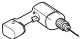
Drill with 3/32" Drill Bit

CUTOUT DIMENSIONS
| Dimension | Trim Kit | Cutout | |
| 27" 30" | |||
| Height 16 | 1/2 " 16 | 1/2 " 15 ± | 1/16 " |
| Width 26 | 7/8 " 29 | 7/8 " 24 | 7/8 ± 1/16 " |
- Min. depth with receptacle outside cutout – 16"
- Min. depth with receptacle inside cutout – 18"
- 120 volt – 60 Hertz grounded power receptacle.
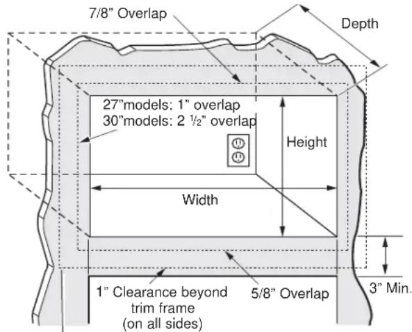
text_image
7/8" Overlap Depth 27"models: 1" overlap 30"models: 2 ½" overlap Height Width 1" Clearance beyond trim frame (on all sides) 5/8" Overlap 3" Min.Bottom of trim kit must be minimum of 36" from floor
WARNING
— This trim kit uses air flow from
the top, bottom and sides of the trim frame. Blocking the air flow can cause the microwave to function improperly and may cause damage to the microwave.
- Allow a 1" clearance beyond the edge of the trim frame to provide proper air flow.
FOR INSTALLATION ABOVE A BUILT-IN OVEN:
Microwave oven should be installed on a 3/8" plywood base and supported by 2x4 or 1x2 equivalent runners on all sides. Base must be capable of supporting a minimum of 100 lbs.
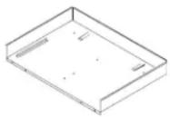
1 LOCATE AND INSTALL THE BASE PAN
Set Base Pan into the front cabinet microwave oven cutout and center it right and left. Push back until the front flange is against the cabinet front wall. Mount the Base Pan using 3 short screws (A).

text_image
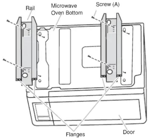
Screw A Base Pan Mounting Holes2 INSTALL THE RAILS
Disconnect the microwave oven from the receptacle. Remove everything out of the microwave oven, including packing, Owner's Manuals, turntable and turntable support. A protective film has been applied to some microwave oven and trim kits. If applied, remove the film. Turn over the microwave oven and secure the rails to oven Base Plate by inserting 4 screws (A). Be careful not to scratch the microwave oven.
text_image
Rail Microwave Oven Bottom Screw (A) Flanges DoorPlug the power cord into the wall receptacle. Slide the microwave oven assembly gently into the cabinet, using care not to pinch the power cord. Be sure to keep the assembly centered as it slides back to where the tongue of the rails goes through the slots on Base Plan. The top edges of the Base Plan should now be centered right to left in the opening. The Base should be tight against the cabinet.

text_image
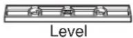
Rail Guides Rails4 CHECK LEVELING
Check the leveling by placing a level at the front and sides of the microwave. It may be necessary to add wood shims under the base pan to level the microwave front-to-back or side-to-side.

natural_image
Line drawing of hands operating a microwave oven with control knobs (no text or symbols)5 SECURE THE RAILS TO THE CABINET
Ensure the Base Pan and Bottom Bracket front flanges are tight against the cabinet, and that the screws holes are aligned. Drive 4 screws (A) through the Base Pan and Rails into the cabinet
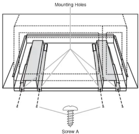
text_image
Mounting Holes Screw A6 INSTALL THE TRIM KIT FRAME
A Position the assembled Trim Kit frame around the oven.
B Secure the Trim Kit by driving four screws (B) through the trim kit into the cabinet.
⚠ CAUTION — Start all screws before tightening any one screw. Do not overtighten screws since it can cause misalignment of top/side strips.

natural_image
Technical line drawing of a mechanical assembly with screw and nut components (no text or symbols)7 REPLACE ANY LOOSE ITEMS
A Your trim kit is now fully installed. Replace the turntable and turntable support that was removed from inside the microwave oven.
B Keep these installation instructions and extra screws for future reference and need. Do not place them in the microwave oven.
C Replace the house fuse, or close the circuit breaker to restore power at the service panel.
READ CAREFULLY. KEEP THESE INSTRUCTIONS.