SRA975XGH - Cooker SMEG - Free user manual and instructions
Find the device manual for free SRA975XGH SMEG in PDF.

User questions about SRA975XGH SMEG
0 question about this device. Answer the ones you know or ask your own.
Ask a new question about this device
Download the instructions for your Cooker in PDF format for free! Find your manual SRA975XGH - SMEG and take your electronic device back in hand. On this page are published all the documents necessary for the use of your device. SRA975XGH by SMEG.
USER MANUAL SRA975XGH SMEG
Thank you for choosing our product.
We advise you to read this manual carefully. It contains all necessary instructions for maintaining unaltered the appearance and functional qualities of the hob.

NSTRUCTIONS FOR THE INSTALLER: these are for the authorised persons who must carry out a suitable check of the gas system, install the appliance, set it functioning and carry out an inspection test.

INSTRUCTIONS FOR THE USER: these contain user advice, description of the commands and the correct procedures for cleaning and maintenance of the appliance.
1. INSTRUCTIONS FOR SAFE AND PROPER USE
THIS MANUAL IS AN INTEGRAL PART OF THE APPLIANCE AND THEREFORE MUST BE KEPT IN ITS ENTIRETY AND IN AN ACCESSIBLE PLACE FOR THE WHOLE WORKING LIFE OF THE HOB. WE ADVISE READING THIS MANUAL AND ALL THE INSTRUCTIONS THEREIN BEFORE USING THE HOB.
INSTALLATION MUST BE CARRIED OUT BY AN AUTHORISED PERSON IN ACCORDANCE WITH THE REGULATIONS IN FORCE. THIS APPLIANCE IS INTENDED FOR DOMESTIC USES AND CONFORMS TO CURRENT REGULATIONS IN FORCE. THE APPLIANCE HAS BEEN BUILT TO CARRY OUT THE FOLLOWING FUNCTIONS: COOKING AND HEATING-UP OF FOOD. ALL OTHER USES ARE CONSIDERED IMPROPER.
THE MANUFACTURER DECLINES ALL RESPONSIBILITY FOR IMPROPER USE.

DO NOT LEAVE THE PACKING IN THE HOME ENVIRONMENT. SEPARATE THE VARIOUS WASTE MATERIALS AND TAKE THEM TO THE NEAREST SPECIAL GARBAGE COLLECTION CENTRE.

IT IS OBLIGATORY FOR THE ELECTRICAL SYSTEM TO BE GROUNDED ACCORDING TO THE METHODS REQUIRED BY SAFETY RULES.

THE PLUG TO BE CONNECTED TO THE POWER CABLE AND THE SOCKET MUST BE THE SAME TYPE AND MUST CONFORM TO CURRENT REGULATIONS.
NEVER ATTEMPT TO REPAIR THE APPLIANCE.

ALWAYS CHECK THAT THE CONTROL KNOBS ARE IN THE POSITION "ZERO" (OFF) WHEN YOU FINISH USING THE HOB.
Introduction
THE IDENTIFICATION PLATE, WITH TECHNICAL DATA, SERIAL NUMBER AND MARKING IS CLEARLY VISIBLE UNDER THE CASING.
THE DUPLICATE DATA PLATE MUST BE ATTACHED TO AN ADJACENT SURFACE.
BEFORE CONNECTING THE DEVICE, MAKE SURE THAT IT HAS BEEN REGULATED FOR THE TYPE OF GAS THAT WILL FEED IT, CHECKING THE LABEL UNDER THE CASING.
DO NOT PUT PANS WITHOUT PERFECTLY SMOOTH AND FLAT BOTTOMS ON THE HOB GRIDS.

DO NOT USE RECIPIENTS OR GRIDDLE PLATES THAT EXTEND BEYOND THE EXTERNAL PERIMETER OF THE HOB.

THE HOB IS TO BE USED BY ADULTS ONLY. DO NOT LET UNSUPERVISED CHILDREN PLAY WITH THE HOB.

REPLACED APPLIANCES MUST BE TAKEN TO A SPECIAL GARBAGE COLLECTION CENTRE.

WHERE THIS APPLIANCE IS INSTALLED IN MARINE CRAFT OR IN CARAVANS, IT SHALL NOT BE USED AS A SPACE HEATER.

THIS APPLIANCE IS DESIGNED FOR COOKING FOOD AND IT SHALL NOT BE USED AS A SPACE HEATER. DO NOT MODIFY THIS APPLIANCE.
DO NOT SPRAY AEROSOLS IN THE VICINITY OF THIS APPLIANCE WHILE IT IS IN OPERATION. DO NOT USE OR STORE FLAMMABLE MATERIAL IN THE STORAGE DRAWER OR NEAR THIS APPLIANCE.

The manufacturer declines all responsibility for damage to persons or things caused by non-observance of the above prescriptions or by interference with any part of the appliance or by the use of non-original spares.
2. POSITIONING OF THE HOB
It is the law that all gas appliances are installed by authorised persons. Clearance around the appliance must comply with the requirements of AS5601.
The following operation requires building and/or carpentry work so must be carried out by a competent tradesman. Installation can be carried out on various materials such as masonry, metal, solid wood or plastic laminated wood as long as they are heat resistant (T 90°C).
2.1 Attachment to support structure
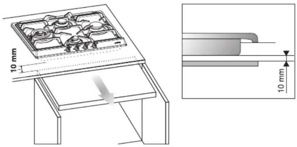
Create an opening with the dimensions shown in the figure in the top surface of the counter, keeping a minimum distance of 50 mm from the rear border. This appliance is classified as "type Y" in relation to fire hazards and can therefore be mounted against walls higher than the work surface on condition that a certain distance "X" be kept between the appliance and the wall as shown in the figure so as to avoid damage from overheating. Make sure there is a minimum of 600 mm between the hot plate flames and any combustible shelf that may be installed directly above them.

text_image
30 20÷40 600 50 478÷482 120 252÷256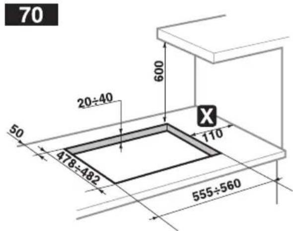
text_image
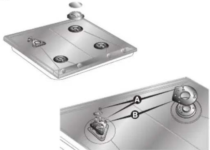
70 20÷40 600 50 478÷482 110 555÷560Accurately position the gasket provided all around the outer edge of the hole in the top surface as shown in the figures below, pressing it down so as to make it adhere properly. For measurements, refer to the figure depending on the hob model to be installed, bearing in mind that in both models the front and rear sides must skim the hole. Secure the hob to the counter with brackets A (supplied). Carefully trim any excess from border B of the gasket. The distances in the following drawing refer to the hole on the inner side of the gasket.
Overall dimensions: location of gas and electrical connection points (all measures in mm).
Instructions for the installer

text_image
500 300 = 30 cm hob 680 = 70 cm hob 40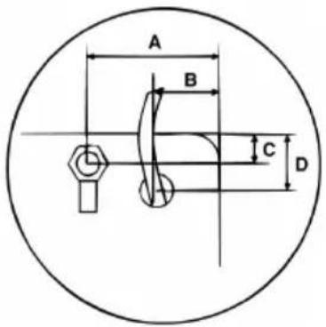
text_image
A B C D60 CM HOB 70 CM HOB
A 60 120
B 90 90
C 30 30
D 90 70
2.2 Clearance above and around domestic appliances
Extract from AS5601

text_image
THE TWO INSETS RELATE TO REQUIREMENT 3 BELOW Horizontal combustible surface below hob Hob E OR Trivet Horizontal combustible surface above trivet NOTE: in this case, any vertical combustible surface needs to be protected to conform with requirement 2 belowREQUIREMENTS
1 Overhead clearances – (Measurement A)
Range hoods and exhaust fans shall be installed in accordance with the manufacturer's instructions. However, in no case shall the clearance between the highest part of the highest burner of the cooking appliance and a range hood be less than 600 mm or, for an overhead exhaust fan, 750 mm.
Any other downward facing combustible surface less than 600 mm above the highest part of the hob shall be protected for the full width and depth of the cooking surface area in accordance with Clause 5.12.1.2. However, in no case shall this clearance to any surface be less than 450 mm.
2 Side clearances – (Measurements B & C)
Where B, measured from the periphery of the nearest burner to any vertical combustible surface, is less than 200 mm, the surface shall be protected in accordance with Clause 5.12.1.2 to a height C of not less than 150 mm above the hob for the full dimension (width or depth) of the cooking surface area. Where the cooking appliance is fitted with a 'splashback', protection of the rear wall is not required.
3 Additional requirements for Freestanding and Elevated Cooking Appliances – (Measurements D & E)
Where D, the distance from the periphery of the nearest burner to a horizontal combustible surface is less than 200 mm, then E shall be 10 mm or more, or the horizontal surface shall be above the trivet. See insets above.
NOTES
1 Requirement 3 does not apply to a freestanding or elevated cooking appliance which is designed to prevent flames or the cooking vessels from extending beyond the periphery of the appliance.
2 The ‘cooking surface area’ is defined as that part of the appliance where cooking normally takes place and does not include those parts of the appliance containing control knobs.
3 For definition of hob, see Clause 1.4.64.
4 For definition of trivet, see Clause 1.4.109.
5 Consideration is to be given to window treatments when located near cooking appliances. See Clause 5.3.4.
2.3 Room ventilation
Caution – This hob may only be installed and operated in rooms permanently ventilated in accordance with current regulations, AS/NZS5601.
2.4 Discharge of combustion products
Discharge of combustion products must be guaranteed by means of hoods connected to a natural draught flue or by means of forced aspiration, e.g. range hood.
In case of installation on an empty kitchen unit with doors, a separation panel must be placed under the hob. Keep a minimum distance of 10 mm between the bottom of the hob and the surface of the panel, which must be easily extractable to allow sufficient access for any technical assistance.
text_image
10 mm 10 mm3. GAS CONNECTION
This appliance is suitable for installation with Natural Gas or ULPG (propane). Refer to page 13 and 14 for the relevant burner pressure and appropriate injector sizes. When the appliance is to be connected to Natural Gas then the pressure regulator supplied must be fitted to the gas inlet. A test point (for checking the gas pressure) is supplied either with the regulator or as a separate fitting in the case of ULPG (propane) appliances.
Connection of the appliance to the gas supply must be in accordance with the requirements of AS5601. A 12 " BSP connector at the inlet is recommended and the gas supply line to the appliance must be of adequate length to allow sufficient withdrawal of appliance for service or disconnection and be:
- annealed copper pipe or;
- flexible hose according to AS/NZ1869 & be at least Class "B", 10 mm diameter, 1.2mt length.
natural_image
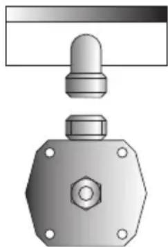
Technical illustration of a mechanical assembly with a knob, nut, and hexagonal nut (no text or symbols)The appliance must be installed with provision to allow the gas to be turned off and disconnected for servicing and removal of the appliance as required from the gas supply.
Before the appliance is operated make certain all relevant parts are placed in the correct position.
When the installation is completed the installation connections of appliance will require to be leak tested, the burner operating pressure and flame checked and adjusted.
Warranty service calls do not cover these adjustments!
To check the operating pressure of the appliance it is recommended at least 2 large size burners are used. Ensure appliance is secured to wall when installation is completed.
N.G. The regulator supplied must be fitted to the 12 BSP thread at the rear of the appliance. An approved manual shut-off valve must be installed. The N.G. regulator must be checked and adjusted to 1.0kPa after installation.
ULPG: Can be connected to the inlet fitting directly. The pressure must be checked to ensure it is operating at 2.75kPa. A separate test point fitting must be installed between the piping & the appliance for the pressure to be checked to ensure it is operating at 2.75kPa.

natural_image
Illustration of two types of pipe fittings: a cylindrical tube and a curved pipe with threaded ends (no text or symbols)Instructions for the installer

4. ELECTRICAL CONNECTION
Make sure that the voltage and capacity of the power line conform to the data shown on the plate located under the casing. Do not remove this plate for any reason.
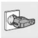
The plug on the end of the supply cable and the wall socket must be the same type and conform to the current electrical system regulations. Check that the power line is adequately grounded.

On the power line, install an omnipolar cut-off device with contact cut-off distance greater than or equal to 3 mm, located in an easily accessible position near the unit.

Do not use reducers, adapters or shunts.

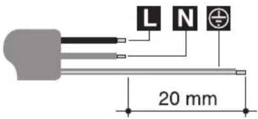
If the power cable is replaced, the wire section on the new cable must not be less than 1.0 mm^2 (3 x 1.0 cable), keeping in mind that the end to be connected to the hob must have the ground wire (yellow-green) longer by at least 20 mm. Use only H05V2V2-F cable or similar which has a maximum temperature of 90^ . Any replacement needed should be carried out by a specialised technician who should make the mains connections according to the following diagram.
$$ \mathbf {L} = \text { brown } $$
$$ \mathbf {N} = \text { blue } $$
$$ ⓧ = \text { yellow - green } $$
text_image
L N 20 mm
The manufacturer will not be liable for any damage to persons or property caused by non-observance of the above instructions or deriving from the tampering of even a single part of the hob.
5. ADAPTATION TO DIFFERENT TYPES OF GAS

Before performing any cleaning or maintenance work, detach the appliance from the electrical socket.
The hob has been adjusted for natural gas at a pressure of 1.0kPa.
For functioning with other types of gas the nozzles must be replaced and the primary air adjusted.
To replace the nozzles and regulate the burners, you have to remove the top as described in the following paragraph.
5.1 Removing the hob
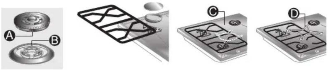
- Remove all the knobs, the grids, the burner caps and the flame-caps;
- remove the screws and the nuts A that secure the burner supports;
- remove plates B;
- lift the hob from its seat;
- replace the burner nozzles in accordance with the reference gas chart;
- regulate the primary air as described in paragraph "5.2 Adjustment for ULPG".
text_image
Technical diagram showing two mechanical components with labeled parts A and B, likely illustrating a gear or linkage mechanism.5.2 Adjustment for ULPG
Loosen screw A and push support B all the way. Use a double head wrench to remove nozzle C and assemble the suitable one, following the instructions indicated in the reference charts, with respect to the type of gas to use. The screwing torque of the nozzle should never exceed 3 Nm. Reposition support B so that nozzle C is covered perfectly.
Place the burner on its support and ignite it. Move the Venturi tube D to regulate the air flow until the flame is stable and burns regularly, then secure the tube by means of screw A.

text_image
A B C D X B A D| Burner (*) | ULPG – 2.75 kPa | ||
| Nominal gas consumption (MJ/h) | Injector (mm) | ||
| Auxiliary (1) 4.8 0.60 | |||
| Semi rapid (2) 6.0 0.68 | |||
| Rapid (6) 9.5 0.85 | |||
| Rapid (3) 12.5 0.95 | |||
| Wok (4) 15.0 1.05 | |||
| Wok (dual control) (5) 18.2 - | |||
| Oute | r | 14.4 0.98 | |
| Inne | r | 3.8 0.48 | |
(*) For burner reference numbers, see page 14.
5.3 Adjustment for natural gas
The hob has been adjusted for natural gas at a pressure of 1.0kPa. To allow the unit to work back with this type of gas, after it has been adjusted for ULPG, perform the same operations described in paragraph "5.2 Adjustment for ULPG", but refer to the following table for the proper injectors.
| Burner (*) | NG – 1.0 kPa | ||
| Nominal gas consumption (MJ/h) | Injector (mm) | ||
| Auxiliary (1) 4.8 0.98 | |||
| Semi rapid (2) 6.0 1.10 | |||
| Rapid (6) 11.5 1.50 | |||
| Rapid (3) 12.2 1.55 | |||
| Wok (4) 15.0 1.70 | |||
| Wok (dual control) (5) 18.8 - | |||
| Oute | r | 14.0 1.65 | |
| Inne | r | 4.8 0.98 | |
(*) For burner reference numbers, see page 14.
6. FINAL OPERATIONS
Having carried out the above adjustments, reassemble the appliance following, backwards, the instructions in paragraph "5.1 Removing the hob".
6.1 Adjustment of minimum for natural gas
Light the burner and take it to the minimum △ Remove the gas tap knob and turn the adjustment screw inside or at the side of the tap shaft (depending on the model) until there is a regular minimum flame. Replace the knob and check burner flame stability: (rapidly turning the knob from maximum to minimum position, the flame should not go out). Repeat the operation on all the gas taps.
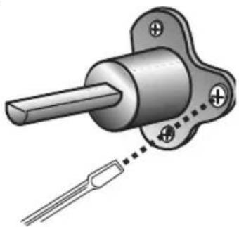
natural_image
Mechanical component diagram showing a shaft and mounting bracket with a dotted line indicating connection (no text or symbols)6.2 Arrangement of burners on the hob

text_image
⑤ ③ ② ① ②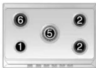
text_image
④ ② 1 ③# # # # #

text_image
⑤ ① ⑥ ① ②Burners
1 Auxiliary
2 Semi rapid
3 - 6 Rapid
4 Wok
5 Wok (dual control)

text_image
④ ② ① ②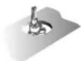
6.3 Lubrication of gas taps
With time it may happen that the gas taps get blocked and hard to turn. Clean them inside and re-grease them. This operation must be done by an authorised person.
Instructions for the installer
7. USING THE HOB

Before turning on the burners, make sure that the burner rings, caps and grids have been fitted correctly.
In the wok burner, the flame spreader crowns must be correctly positioned in their seats.
Grid C provided is intended for use with woks (Chinese pans).
Adapter D comes only with open grids models and is intended for use with small sized vessels.
text_image
Technical diagram showing four labeled views of a mechanical component with parts A, B, C, and D.7.1 Ignition of the burners

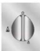
On some models raised indicators make for easier and clearer reading and use of the controls, each knob being connected to its corresponding burner by a rib. Setting corresponds to the elongated part of the knob or to the marking on it.
(Only where applicable)
Double-crown burners, controlled by two knobs, feature two ribs, a long one corresponding to the small inner burner and a short one to the outer burner.
Double-crown burners comprise an auxiliary and a rapid burner, controlled by two different knobs which permit to use both burners at the same time or to select one or the other as required.
The device is fit with electronic ignition. Simply press and simultaneously turn the knob counter-clockwise on any position between the high flame and the low flame symbol, until the burner is ignited. Concerning models with valves, push the knob for approximately 2 seconds in order to keep the flame burning and to activate the safety device. The burner might go off when the knob is released. In this case repeat the aforesaid operation keeping the knob pressed for more than 2 seconds.
Should the burners go off accidentally in the models with valves, a safety device will trip after approximately 20 seconds to block the gas outlet even if the tap is open.
7.2 Practical advice for using the burners
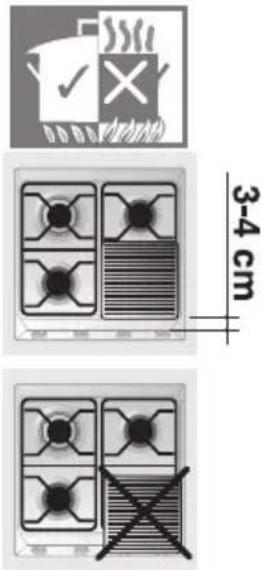
For better use of the burners and lower gas consumption, use covered containers that are proportional in size to the burner to prevent the flame from licking the sides (see paragraph "7.3 Diameter of containers"). When water reaches the boiling point, lower the flame so that it doesn't overflow. To avoid burns or damage to the hob, all recipients or griddle plates must be placed within the perimeter of the hob, at a distance of 3-4 cm from the knobs. All containers have to have a flat and smooth bottom. When using fats or oils, be extremely careful that they don't overheat and catch fire. If the flame accidentally goes out, turn off the control knob and wait at least 1 minute before trying to re-light the burner.
text_image
3-4 cm7.3 Diameter of containers

(*) Burner ∅ min. and max. (in cm)
1 Auxiliary 12-14
2 Semi rapid 16-20
3 - 6 Rapid 22-26
4 Wok 22-26
5 Wok (dual control) 12-34
(*) For burner reference numbers, see page 14.
8. CLEANING AND MAINTENANCE
Before any intervention, disconnect the power supply of the device.
8.1 Cleaning
Clean the top regularly every time you use it, obviously after it has cooled.
8.1.1 Regular daily cleaning of the hob
In order to clean and preserve the surface, always use specific products only, which do not contain abrasive substances or chlorine-based acid substances.
How to use: pour the product on a damp cloth and wipe the surface, rinse thoroughly and dry with a soft cloth or deerskin.
8.1.2 Food stains or residues
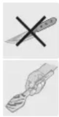
Do not use metallic sponges or sharp scrapers: they will damage the surface.
Use normal non-abrasive products and remove spots or residuals with non-scratch sponges or, if need be, with wood or plastic utensils.
Rinse thoroughly and dry with a soft cloth or deerskin.
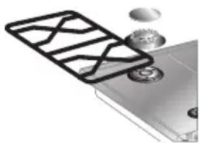
8.2 Cleaning of the hob components
Grids, caps, flame cap crowns and burners can be removed for ease of cleaning. Wash them in warm water using a non-abrasive detergent, taking care to remove all tough spots. Before remounting, allow the components to fully dry out.
natural_image
Illustration of a smartphone with a grid pattern and coins on top (no text or symbols)
8.2.1 Ignition plugs and safety devices
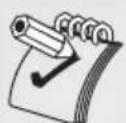
For good functioning of the lighting ignition plugs and the safety devices, keep them very clean.
Check frequently and clean with a damp cloth when necessary.

natural_image
Illustration of a magnifying glass with a handle and lens (no text or symbols)8.3 Preventive maintenance
This appliance does not need any special maintenance. However, a few simple operations have to be carried out periodically to prevent malfunctioning:
Burners: the burners must be cleaned after every use to ensure correct combustion; make sure that all the openings and flame ports are clean and free of obstacles, and that the burners rest firmly on their supports.
Gas connection: the gas connection must be checked periodically (at least every 2 years). Each time the cooker is moved the connection may be stressed: test it for leakages using special sprays or a solution of soap and water.
Flexible pipes: if a flexible pipe is used, it must be inspected periodically (once a year) for leakages: if the surface of the pipe appears rigid and cracked, disconnect immediately the cooker from the gas supply and replace the pipe with a new one.
Valves: if the gas valves get stuck or hard to turn, they need to be cleaned and re-greased; this operation must be carried out by an authorised person.
9. PROBLEMS AND CAUSES
Each of the following cases is caused by an abnormal operation of the appliance and should be dealt with by a authorised persons: please contact your local dealer or Service Center in case you detect any of these malfunctioning.
| PROBLEM | CAUSE | WHAT TO DO |
| The flame is very long with bright yellow tips. Black deposits on the bottom of the pans. | Defect of comburent air or incorrect injectors. Burner dirty or flame ports obstructed. | Clean the burner. Call Service Center if the problem remains. |
| The flame is very short and noisy. The flame moves away from the burner ports. | Excess of comburent air. | Call Service Center. |
| The flame extinguishes when the burner knob is set to the low flame position. | Incorrect adjustment of the minimum heat input or excess of comburent air. | Call Service Center. |
| The valve knob is hard to rotate. | Gas valve worn out or needs lubrification. | Call Service Center. |