
Museo 533TPL - Faucets Symmons - Free user manual and instructions
Find the device manual for free Museo 533TPL Symmons in PDF.

| Product Type | Toilet Paper Holder |
| Brand | Symmons |
| Model | Museo 533TPL |
| Material | Brass with polished chrome plating |
| Finish Options | Standard Polished Chrome; Optional: Polished Graphite (-BLK), Satin Nickel (-STN) |
| Mounting Type | Wall-mounted with bracket and screws |
| Dimensions (A) | 2" (51 mm) |
| Dimensions (B) | 1 7/8" (48 mm) |
| Dimensions (C) | 3 7/16" (87 mm) |
| Dimensions (D) | 7 1/2" (191 mm) |
| Dimensions (E) | 5 3/8" (137 mm) |
| Dimensions (F) | 6 1/2" (165 mm) |
| Included Hardware | Mounting Hardware Kit (RA-017) |
| Required Tools | 3/16" Allen wrench, Phillips screwdriver, power drill |
| Installation Options | Dry wall (with toggle anchors) or stud mounting |
| Warranty | Limited Lifetime (consumer), 5 years (commercial) |
| Care Instructions | Clean with mild soap and water; avoid abrasive cleaners |
| Safety Compliance | California Proposition 65 warning for lead and other chemicals |
| Replacement Parts | Mounting Hardware Kit RA-017 |
Frequently Asked Questions - Museo 533TPL Symmons
User questions about Museo 533TPL Symmons
0 question about this device. Answer the ones you know or ask your own.
Ask a new question about this device
Download the instructions for your Faucets in PDF format for free! Find your manual Museo 533TPL - Symmons and take your electronic device back in hand. On this page are published all the documents necessary for the use of your device. Museo 533TPL by Symmons.
USER MANUAL Museo 533TPL Symmons
Operation & Maintenance Manual

natural_image
Illustration of various bathroom fixtures including a towel, shower, and sink (no text or symbols present)| Model Numbers Specifications | |
| ☐ 533RH Robe Hook☐ 533TB-18 18" Towel Bar☐ 533TB-24 24" Towel Bar☐ 533TPL Toilet Paper Holder (left hand) | All premium accessories made from brass plated in standard polished chrome finish. |
| Compliance | |
| ☐ 533TPR Toilet Paper Holder (right hand)☐ 533TR Towel Ring | For California ResidentsWARNING: This product contains chemicals known to the State of California to cause cancer, birth defects, or other reproductive harm. |
| Modifications Warranty | |
| ☐ -BLK Polished graphite finish☐ -STN Satin nickel finish | Limited Lifetime - to the original end purchaser in consumer installations.5 Years - for commercial installations.Refer to www.symmons.com/warranty for complete warranty information. |
| Note: Append appropriate -suffix to model number. |
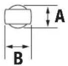
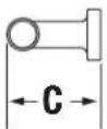
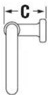
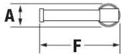
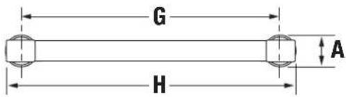
Dimensions
533RH
533TR

533TPR


533TPL

533TB-18

533TB-24


Measurements
| A 2", 51 mm |
| B 1 7/8", 48 mm |
| C 3 7/16", 87 mm |
| D 7 1/2", 191 mm |
| E 5 3/8", 137 mm |
| F 6 1/2", 165 mm |
| G 18", 457 mm |
| H 20", 508 mm |
| I 24", 610 mm |
| J 26", 660 mm |
Required for Installation
| Allen wrench (3/16") |  |
| Phillips head screwdriver | 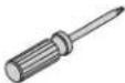 |
| Power drill |  |
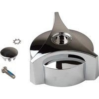
Replacement Parts
| Description Part Number | |
| Mounting Hardware Kit | RA-017 |
Note: Dimensions are subject to change without notice.
Installation
1) Measure and mark centerlines for mounting bracket installation using dimensions on page 2.
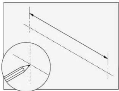
natural_image
Diagram showing a pencil drawing an arrow on a line with a magnified inset (no text or symbols)Notes: 533TB-18 and 533TB-24 only. Make sure both centerline marks are level.
2a) Dry Wall Option: Place mounting brackets into desired position. Using brackets as a guide, mark holes. Push toggle anchors into wall.

Note: For plaster walls 1/2" thick or less, insert toggle tool into toggle to secure behind wall prior to installing accessory trim.
2b) Stud Option: Place mounting brackets into desired position. Using brackets as a guide, carefully drill 3/16" holes into wall.

3) With mounting brackets in position, secure to wall using screws.
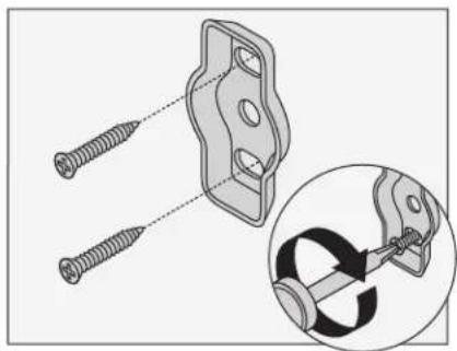
natural_image
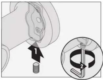
Technical illustration of a mechanical clamp assembly with two screws and a bracket, plus an inset showing the internal mechanism (no text or symbols)4) Hang top of accessory on mounting bracket. Lower into position.

natural_image
Diagram showing a mechanical assembly with a cylindrical component and a separate plate (no text or symbols)
natural_image
Diagram of a mechanical component with a curved arrow indicating rotation (no text or symbols)5) Secure with set screw.
Care and Cleaning
1) Clean finished trim area with a soft cloth using mild soap and water or a non-abrasive cleaner and then quickly rinse with water.


Brand : Symmons
Model : Museo 533TPL
Category : Faucets