
DRRM300BSS - Electric stove DANBY - Free user manual and instructions
Find the device manual for free DRRM300BSS DANBY in PDF.

| Product Type | Electric Range (30 inch) |
| Model Number | DRRM300BSS |
| Dimensions (with backsplash) | 37.9 - 37.12 in H x 29.9 in W x 27.6 in D (96.3 - 94.3 cm x 76 cm x 70 cm) |
| Cooktop Type | Ceramic Glass |
| Number of Cooking Zones | 4 |
| Left Front Burner Power | 2200 W |
| Left Rear Burner Power | 1200 W |
| Right Front Burner Power | 2500 W |
| Right Rear Burner Power | 1200 W |
| Oven Type | Conventional with convection (fan-assisted) |
| Oven Functions | Bake, Broil, Roast, Light |
| Temperature Range | 150°F - 500°F (66°C - 260°C) |
| Timer | Mechanical timer (60 minutes max) |
| Control Type | Knobs (6 knobs: 4 burners, oven settings, temperature) |
| Safety Features | Anti-tip bracket, hot surface indicator, oven door removal |
| Oven Cleaning | Manual cleaning (not self-cleaning) |
| Cooktop Cleaning | Ceramic cooktop cleaner and scraper recommended |
| Accessories Included | Backsplash, 2 oven racks, anti-tip bracket kit with screws |
| Power Supply | Requires dedicated circuit, 240V, 40A or 50A; 4-wire or 3-wire connection (power cord not included) |
| Installation | Leveling legs, anti-tip bracket must be installed |
| Warranty | 24 months limited in-home warranty |
| Oven Light | 25W appliance bulb (replaceable) |
| Door Removal | Yes, for cleaning or servicing |
| Material | Stainless steel exterior, porcelain enamel interior |
Frequently Asked Questions - DRRM300BSS DANBY
User questions about DRRM300BSS DANBY
0 question about this device. Answer the ones you know or ask your own.
Ask a new question about this device
Download the instructions for your Electric stove in PDF format for free! Find your manual DRRM300BSS - DANBY and take your electronic device back in hand. On this page are published all the documents necessary for the use of your device. DRRM300BSS by DANBY.
USER MANUAL DRRM300BSS DANBY
Owner's Manual....1 - 30
ESTUFA ELÉCTRICA 30"
Manual del proprietario....31 - 60
MODEL • MODÈLE
DRRM300BSS
DRRM300W
Danby Products Limited, Guelph, Ontario, Canada N1H 6Z9
Danby Products Inc. Findlay, Ohio, U.S.A. 45840
www.danby.com
f in x p
Printed in China | Imprimé en Chine | Impreso en China
2024.07.25
Welcome to the Danby family.
We are proud of our quality products and we believe in dependable service. We suggest that you read this owner's manual before plugging in your new appliance as it contains important operation information, safety information, troubleshooting, and maintenance tips to ensure the reliability and longevity of your appliance.
You are entitled to the warranty coverage as described in the owner's manual provided with your new appliance.
- Please write down your appliance information below. You must keep the original proof of purchase receipt to validate and receive warranty services.
- Register your product online and receive a FREE 2 MONTH WARRANTY EXTENSION after filling out a product survey, at www.danby.com/support/product-registration/
Model Number:
Serial Number:
Date of Purchase:
Need Help?
- Read your Owner's Manual for installation help, troubleshooting, and maintenance assistance.
- Visit www.Danby.com to access self-service tools, FAQs and much more by searching your model number in the search bar.
- For the Quickest Customer Service, please fill out the web form at www.danby.com/support. Your submission will go directly to an expert on your particular appliance. Our average response times are between 20 minutes and 2 hours, during EST business hours.
- Call 1-800-263-2629 - please note that during peak hours, hold times can exceed one hour.

Important Safety Information READ AND FOLLOW ALL SAFETY INSTRUCTIONS
WARNING - TIP OVER HAZARD
- A child or adult can tip the appliance and be killed.
- Verify the anti-tip bracket has been properly installed to the floor or wall.
- Ensure the anti-tip bracket is re-engaged when the range is moved.
- Do not operate the range without the anti-tip bracket in place and engaged.
- Failure to follow these instructions can result in death or serious burns to children or adults.
ANTI-TIP DEVICE
To reduce the risk of the range tipping by abnormal usage or improper door loading, the range must be secured by installing an anti-tip device.
Note: If the range is ever relocated the anti-tip bracket must be removed and installed at the new location.
WARNING
SUFFOCATION AND RISK OF CHILD ENTRAPMENT
To avoid the possibility of child entrapment please take the following precautions before throwing out the appliance:
- Remove the oven door completely
- Never allow children to operate, play with or crawl inside the electric range
SAVE THESE INSTRUCTIONS!

Important Safety Information
READ AND FOLLOW ALL SAFETY INSTRUCTIONS
NOTICE - BEFORE FIRST TIME USE OVEN
Before use of this oven for the first time, the heating elements have a protective coating, which must be burned off before use. To do this:
- Remove all packaging from the inside of the oven
- Ensure door is closed
- Rotate the cooking feature knob to Bake.
- Rotate the temperature feature knob to MAX.
- Rotate the timer knob to 30 minutes.
NOTE: Allow the oven to operate for 30 minutes with no food in the cavity. Once it has completed the 30 minutes, open the oven door to allow it to cool. Any odor that may be detected during this initial use is due to the evaporation of substances used to protect the oven during storage.
NOTE: Do not place anything, including dishes, foil and oven trays, on the bottom of the oven when it is in operation to avoid damaging the enamel.
NOTICE - BEFORE FIRST TIME USE COOKTOP
Before use of the cooktop for the first time, the heating elements have a protective coating, which must be burned off before use. To do this:
- Clean the ceramic glass top. It is recommended to use a glass top cleaner.
- Place a saucepan of water on each front burner and turn the heat on HI for at least 30 minutes. Turn off the front burners.
- Repeat previous step for both of the rear burners.
NOTES:
This procedure will evaporate any protective oils and humidity collected during the manufacturing process, and enables the electronic control circuits to operate properly.
There may be a slight odor during the first several uses: this is normal and will dissipate.
After use, the ceramic cooktop will remain hot for over 20 minutes after it has been turned off. The Hot Surface Indicator will remain lit when the cooktop is hot.
SAVE THESE INSTRUCTIONS!

Important Safety Information
READ AND FOLLOW ALL SAFETY INSTRUCTIONS
AREAS NEAR THEM
Heating elements on the surface or in the interior of the appliance may be hot even though they are dark in colour. Areas near the heating elements may become hot enough to cause burns. During and after use do not touch or let clothing or other flammable materials contact the heating elements or areas near them until they have had sufficient time to cool. Surfaces of the appliance may become hot enough to cause burns, among them are the cook top, oven vent openings and surfaces near these openings, oven doors and oven windows.
DANGER - GREASE FIRES
In the event of a fire, never pick up a flaming pot or pan. Turn the element off if it is safe to do so. Extinguish the fire with a dry chemical or foam-type extinguisher.
Do not use water on grease fires. Water will spread the grease and will not extinguish the fire. Smother the fire with a tight fitting pot lid, cookie sheet or flat tray or use dry chemical or foam-type extinguisher.
If there is a fire in the oven while in use, smother the fire by closing the oven door and turning the oven off or use dry chemical or foam-type extinguisher.
DANGER - FIRE RISKDO NOT TO
- It is recommended that this appliance be connected to a separate circuit that is not shared with any other appliance.
- Never clean appliance parts with flammable fluids. These fumes can create a fire hazard or explosion. Never use or store gasoline or other flammable vapors or liquids inside or in the proximity of this appliance, failing to do so may result in a fire hazard or explosion.
- Before cleaning or servicing this appliance, unplug the appliance completely from the electrical outlet or disconnect the range power supply at the household distribution panel by removing the fuse or switching off the circuit breaker. Failure to do so can result in electrical shock or death.
- Do not attempt to repair or replace any part of your appliance unless it is specifically recommended in this manual. All other servicing should be referred to a qualified service technician.
- For your safety, this appliance should never be used as a source of heat or as a space heater. The cooktop elements should not be operated without proper cookware.
- All openings in the wall behind the appliance and the floor under the appliance shall be sealed.
- Keep the area around the appliance clear and free from combustible materials, gasoline and other flammable vapors. Always keep combustible wall coverings, curtains or drapes a safe distance from the range.
- Do not obstruct the flow of air around the appliance.
- Storage in or on the appliance: flammable materials should not be stored in an oven or near cooktop elements.
- Do not cover any slots, holes or passages in the oven bottom or cover an entire rack with materials such as aluminum foil.
SAVE THESE INSTRUCTIONS!

Important Safety Information READ AND FOLLOW ALL SAFETY INSTRUCTIONS
GENERAL SAFETY REQUIREMENTS
Ensure the appliance is properly installed and grounded by a qualified technician.
Children should not be left alone or unattended in the area where the appliance is in use. Children should never be allowed to sit or stand on any part of the appliance.
Do not store items of interest to children in cabinets above a range or on the back guard of a range. Children climbing on the range to reach items could be seriously injured.
To eliminate the risk of burns or fire by reaching over heated surface units, cabinet storage space located above the surface units should be avoided. If cabinet storage is to be provided, the risk can be reduced by installing a range hood that projects horizontally a minimum of 5 inches (12.7 cm) beyond the bottom of the cabinets.
Loose fitting or hanging garments should never be worn while using the appliance.
Use only dry pot holders. Moist or damp pot holders on hot surfaces may result in burns from steam. Do not let the pot holder touch hot heating elements. Do not use a towel or other bulky cloth.
If power is lost to an electric cooktop while a surface element is ON, the surface element will turn back on as soon as power is restored. In the event of power loss, failure to turn all surface element knobs to the OFF position may result in ignition of items on or near the cooktop, leading to serious injury or death.
This range is designed and manufactured solely for the cooking of domestic (household) food and is not suitable for any non domestic application and therefore should not be used in a commercial environment. The range warranty will be void if the range is used within a non domestic environment.
WARNING
To reduce the risk of burns, do not move this appliance while it is hot. To reduce the risk of injury due to tipping of the appliance, verify the re-installation of this appliance into the anti-tipping device provided after returning the appliance to the original installed position.
WARNING
The manufacturer declines all liability for injury to persons or damage to property cause by incorrect or improper use of the range.
SAVE THESE INSTRUCTIONS!

Important Safety Information
READ AND FOLLOW ALL SAFETY INSTRUCTIONS
COOKTOP SAFETY REQUIREMENTS
- Use the proper pan size. This appliance is equipped with four burners of different sizes. Select utensils that have flat bottoms large enough to cover the surface of the heating element. The use of undersized utensils will expose a portion of the heating element to direct contact and may result in ignition of clothing. Proper relationship of utensil to burner will also improve efficiency.
- Never leave the appliance unattended while in use. Boil over causes smoking and greasy spills can ignite.
- Never leave oil unattended while frying. If allowed to heat beyond its smoking point, oil may ignite resulting in fire that may spread to surrounding cabinets. Use a deep fat thermometer whenever possible to monitor oil temperature.
- To avoid oil spillover and fire, use a minimum amount of oil when shallow pan-frying and avoid cooking frozen foods with excessive amounts of ice.
- Only certain types of glass, ceramic, earthenware or other glazed utensils are suitable for range top service without breaking due to sudden change in temperature.
- To reduce risk of burns, ignition of flammable materials and spillage due to unintentional contact, the handle of a utensil should be positioned so that it is turned inward and does not extend over adjacent burners.
- Do not cook on broken cooktop. If the cooktop should break, cleaning solutions and spill overs may penetrate the broken cooktop and create a risk of electric shock. Contact a qualified technician immediately.
- Do not use a griddle or long pan on more than one burner at once.
- Clean Cook-Top With Caution - If a wet sponge or cloth is used to wipe spills on a hot cooking are, be careful to avoid steam burn. Some cleaners can produce noxious fumes if applied to a hot surface.
OVEN SAFETY REQUIREMENTS
Use care when opening the door. Allow hot air or steam to escape before removing or replacing food.
Do not heat unopened food containers. Build up of pressure may cause the container to burst and result in injury.
Keep oven vents unobstructed.
Always place oven racks in the desired location while the oven is cool. If the rack must be moved while the oven is hot, do not let the pot holder contact the hot heating element in the oven.
Do not use the oven if a heating element develops a glowing spot during use or shows other signs of damage. A glowing spot indicates the heating element may fail and present a potential burn, fire, or shock hazard. Turn the oven off immediately and have the heating element replaced by a qualified service technician.
Do not line the oven walls or racks with aluminum foil.
Do not place shelves, pans, baking trays, broil trays or other cooking utensils in the bottom of the oven chamber. Always place on an oven shelf.
Never clean the oven with any high pressure steam cleaning devices.
Do not leave anything on the top of the oven vent. Never cover the oven vent opening with aluminum foil or any other material.
SAVE THESE INSTRUCTIONS!

Important Safety Information READ AND FOLLOW ALL SAFETY INSTRUCTIONS
GROUNDING INSTRUCTIONS
This appliance must be grounded. Grounding reduces the risk of electrical shock by providing an escape wire for the electrical current.
When this appliance is fitted with a power cord that has a grounding wire with a 4-prong plug. The power cord must be plugged into an outlet that is properly grounded. If the outlet is not a 4-prong plug, it must be replaced with a properly grounded 4-prong wall outlet. The rating plate indicates the voltage and frequency the appliance is designed for.
WARNING - Improper use of the grounding plug can result in a risk of electric shock. Consult a qualified electrician if the grounding instructions are not completely understood, or if doubt exists as to whether the appliance is properly grounded.
Do not connect the appliance to extension cords, adapters or together with another appliance in the same wall outlet.
Do not splice the power cord. Do not under any circumstances cut or remove the ground prong from the power cord.
If the power supply cord is damaged, it must be replaced by the manufacturer, its service agent or similar qualified person in order to avoid hazard.
Note: Turning the appliance off does not disconnect the appliance from the power supply.
It is recommended that the power cord and the plug be placed parallel with the floor so that the cord runs parallel with the floor.
INSTALLATION INSTRUCTIONS
Installation Measurements
NOTE: Range can be raised approximately 1 inch (2.5 cm) by adjusting the leveling legs. The front of door and drawer may extend farther forward depending on styling.

natural_image
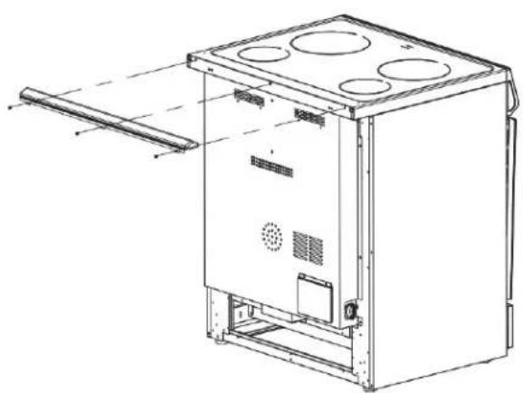
Technical line drawing of a portable oven or stove unit with mounting holes and ventilation slots (no text or symbols)BACKSPLASH INSTALLATION:
Install the backsplash to rear of the range with the screws provided.
Power Supply

A: Access Panel to Electrical Supply Cord
B: Power Cord Opening
C: Recessed Area
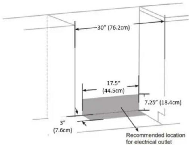
NOTE: To connect to an outlet in the wall, the electrical outlet must be recessed. If the electrical outlet is on the floor, it must be either recessed or surface mounted.
INSTALLATION INSTRUCTIONS
IMPORTANT
Disconnect power before servicing. Improper connection of aluminum house wiring and copper appliance leads can result in an electrical hazard or fire. If the home has aluminum wiring, only use connections designed and UL listed for joining copper to aluminum and precisely follow the manufacturer's recommend procedure. Aluminum-to-Copper connections must conform with local codes. Use 8-gauge copper or 6-gauge aluminum wire. Electrically ground range.
CONNECTION TO HOUSE ELECTRICAL SUPPLY
Be sure your appliance is properly installed and grounded by a qualified technician.
- A circuit breaker is recommended.
- The range can be connected directly to the circuit breaker box (or fused disconnect) through flexible or nonmetallic sheathed, copper or aluminum cable.
- Allow at least 6 ft (1.8M) of slack in the line so that the range can be moved if servicing is every necessary.
- A UL listed conduit connector must be provided at each end of the power supply cable (at the range and at the junction box).
The wiring diagram is included with the range. This appliance is manufactured with the chassis connected to a neutral by a green ground jumper wire. After making sure that the power has been turned off, connect the flexible conduit from the range to the junction box using a UL listed conduit connector. The Grounded Neutral and Ungrounded Neutral Graphics on the following pages and the instruction provided, present the most common way of connecting the range. Your local codes and ordinances take precedence over these instruction. Complete electrical connections according to local codes and ordinances.
PARTS NEEDED:
If using a power supply cord:
- UL listed power supply cord kit marked for use with ranges. The cord should be rated at 250V minimum, 40 amps or 50 amps that is marked for use with nominal 1 3/8" (3.5 cm) diameter connection opening and must end in ring terminals or open-end spade terminals with upturned ends.
- UL listed strain relief.
If direct wiring:
• Flexible Metal Conduit
- UL Listed Conduit Connector
- 4-wire or 3-wire Electrical Cable (where local codes permit a 3-wire connection)
- UL Listed Wire Connectors
NOTES:
- Check local codes.
- Check existing electrical supply.
INSTALLATION INSTRUCTIONS
IMPORTANT
Only for models sold in the United States. This model does not include a pre-installed power cord. Use the following wiring instructions before using the range. The power cord is not provided. Follow all local and national wiring codes and standards.
3-WIRE POWER CABLE INSTALLATION
WARNING: Use this method only if local codes permit connecting chassis ground conductor to neutral wire of power supply cord.
- Feed the electric cable wires through the flexible metal conduit.
NOTE: Allow enough slack to easily attach the wires to the terminal block.
- Remove the access panel located on the bottom right-hand side of the back panel to uncover the electrical terminal block.
- Install a UL listed strain relief to the flexible metal conduit opening in the support bracket and fully tighten the strain relief nut.
- Feed the flexible metal conduit through the strain relief
NOTE: Allow enough slack to easily attach the wiring to the terminal block.

A: Jumper Wire (not provided)
B: UL Listed Strain Relief
C: Conduit
- Using a 5/16" nut driver and one of the 10-32 hex nuts, connect the ground (green or bare) wire from the flexible metal conduit to the center terminal block post along with the green jumper wire from the range.
- Using 10-32 hex nuts, connect the red and black wires from the power cord to the outer posts of the terminal block with the corresponding red and black wires from the range.
- Tighten the hex nuts completely and then verify the connection.
- Position the lower part of the strain relief under the flexible metal conduit and tighten the strain relief screws.
NOTE: Before tightening, make sure the strain relief is positioned over the flexible metal conduit and NOT the wires.
- Replace the electrical access panel.
- Tuck excess conduit into the recessed are of the back panel.
INSTALLATION INSTRUCTIONS
IMPORTANT
Grounding through the neutral conductor is prohibited for new branch-circuit installations (1996 NEC); mobile homes; and recreational vehicles, or in an area where local codes prohibit grounding through the neutral conductor. For installations where grounding through the neutral conductor is prohibited, see the Ungrounded Neutral graphic. Use grounding terminal or lead to ground unit. Connect neutral terminal or lead to branch circuit neutral in usual manner.
3-WIRE POWER CABLE CONNECTION TO HOUSE ELECTRICAL SUPPLY
NOTE: Use the 3-wire cable from home power supply where local codes permit a 3-wire connection.
- Disconnect power.
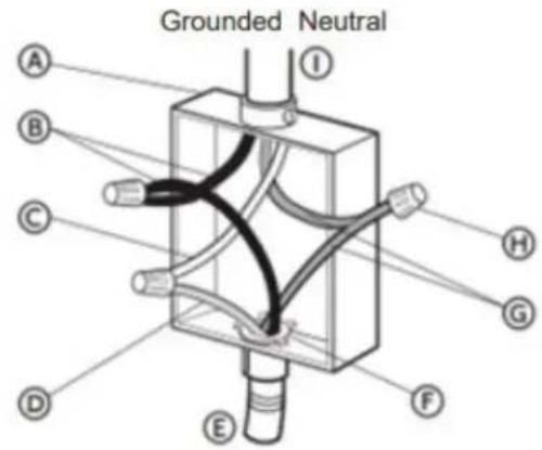
A: Junction Box
B: Black Wires
C: Neutral (white) Wire
D: Ground (green or bare) Wire
E: Cable from range
F: UL Listed Conduit Connector
G: Red Wires
H: UL Listed Wire Connectors
I: House Electrical Supply
- Connect the 2 black wires together using a UL listed wire connector.
- Connect the neutral (white) wire and the ground (green or bare) wire (of the range cable) using a UL listed wire connector.
- Connect the 2 red wires together using a UL listed wire connector.
- Install junction box cover.
INSTALLATION INSTRUCTIONS
IMPORTANT
Only for models sold in the United States. This model does not include a pre-installed power cord. Use the following wiring instructions before using the range. The power cord is not provided. Follow all local and national wiring codes and standards.
4-WIRE POWER CABLE INSTALLATION
NOTE: Use this method for new branch-circuit-installations (1996 nec), mobile homes, recreational vehicles, or in an area where local codes prohibit grounding through the neutral wire.
- Feed the electric cable wires through the flexible metal conduit.
NOTE: Allow enough slack to easily attach the wires to the terminal block.
- Remove the access panel located on the bottom right-hand side of the back panel to expose the electrical terminal block.
- Install a UL listed strain relief to the flexible metal conduit opening in the support brack and fully tighten the strain relief nut.
- Feed the flexible metal conduit through the strain relief. Allow enough slack to easily attach the wiring to the terminal block.

A: Ground Screw
B: Terminal Block
C: UL Listed Strain Relief
- Remove the green jumper wire from under the ground screw and replace with the green wire from the power cord, tighten ground screw. from the flexible metal conduit and tighten ground screw.
- Loop the green jumper wire removed from the ground screw back onto its end that is fastened to the center post on the terminal block.
- Use a 5/15" nut driver to connect the neutral (white) wire to the center terminal block post with one of the 10-32 hex nuts.
- Using 10-32 hex nuts, connect the red and black wires from the power cord to the outer posts of the terminal block with the corresponding red and black wires from the range.
- Tighten the hex nuts completely and then verify the connection
- Position the lower part of the strain relief under the flexible metal conduit and tighten the strain relief screws.
NOTE: Before tightening, make sure the strain relief is positioned over the flexible metal conduit and NOT the wires.
- Replace the electrical access panel.
- Tuck excess conduit into the recessed area of the back panel.
INSTALLATION INSTRUCTIONS
IMPORTANT
Use the 4-wire cable from home power supply where local codes do not allow grounding through neutral, new branch circuit installation (1996 NEC), mobile homes and recreational vehicles, new construction.
4-WIRE POWER CABLE CONNECTION TO HOUSE ELECTRICAL SUPPLY
Ungrounded Neutral
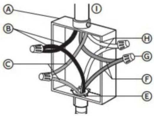
A: Junction Box
B: Black Wires
C: Ground (green or bare) Wires
D: Cable from range
E: UL Listed Conduit Connector
F: Red Wires
G: UL Listed Wire Connectors
H: Neutral (white) Wires
I: House Electrical Supply
INSTALLATION INSTRUCTIONS
Gather the required tools and parts before starting installation.
REQUIRED TOOLS
- Tape Measure
- Flat Blade Screwdriver
- Phillips Screwdriver
- Level
- Cordless Electric Drill
- Hammer
- Wrench or Pliers
- Metal Saw
- Metal Snips or Large Wire Cutters
- 15/N6" Combination Wrench
- 3/8" Nut Driver
- 1/4" Nut Driver
- 1/8" (3.2mm) Drill Bit (for wood floors)
- Marker or Pencil
- Masking Tape
LOCATION REQUIREMENT
Ventilation
It is the installer's responsibility to comply with installation clearances, if specified, on the model/serial rating plate. The model/serial rating plate is located on the rear side of the oven frame. Open the oven door to view the label. See label on the back panel of the range for additional element and oven power ratings.
NOTE: Observe all governing codes and ordinances.
Temperature
- The range should be located for convenient use in the kitchen.
- Recessed installations must provide complete enclosure of the sides and rear of the range.
- To eliminate the risk of burns or fire by reaching over heated surface units, cabinet storage space located above the surface units should be avoided. If cabinet storage is to be provided, the risk can be reduced by installing a range hood or microwave hood combination that projects horizontally a minimum of 5 inches (12.7 cm) beyond the bottom of the cabinets.
- All openings in the wall or floor were the range is to be installed must be sealed.
- Do not seal the range to the side cabinets.
- Ground electric supply is required. See "Electrical Requirements" section.
NOTE: Some cabinet and building materials are not designed to withstand the heat produced by the oven for baking and self-cleaning. Check with your builder or cabinet supplier to make sure that the material used will not discolour, delaminate or sustain other damage.
- Contact a qualified floor covering installer to check that the floor covering can withstand at least 200°F (93°C).
- Use an insulated pad or 1/4 inch (0.64cm) plywood under range if installing range over carpeting.
INSTALLATION INSTRUCTIONS
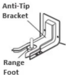
ANTI-TIP BRACKET
An anti-tip bracket kit is provided with the range.
WARNING: Tip Over Hazard
- A child or adult can tip the range and be seriously injured.
- Connect the anti-tip bracket to the rear foot of the range.
- Reconnect the anti-tip bracket if the range is moved.
NOTE: DO NOT completely remove the rear leveling leg. The anti-tip bracket uses either the right-hand or left-hand rear leveling leg to secure the range to the floor or wall.
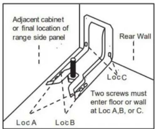
Bracket Location
Determine the final location of the range before attempting to install the bracket.
Place the bracket on the floor with the back edge against the rear wall. If the range does not reach the rear wall, align the back edge of the bracket with the rear panel of the range in its final location.
NOTE: If the bracket does not touch the rear wall, you MUST screw the bracket to the FLOOR.
Position the site of the bracket against either the left or right cabinet. If there is no adjacent cabinet, align the edge of the bracket with the side panel of the range in its final location. If the countertop overhangs the cabinet, offset the bracket from the cabinet by the amount of overhang.
Mark the location for the pair of holes to be used (see illustration below).
NOTE: For FLOOR installation use either Loc A or B. For REAR WALL installation use Loc C.
INSTALLATION INSTRUCTIONS
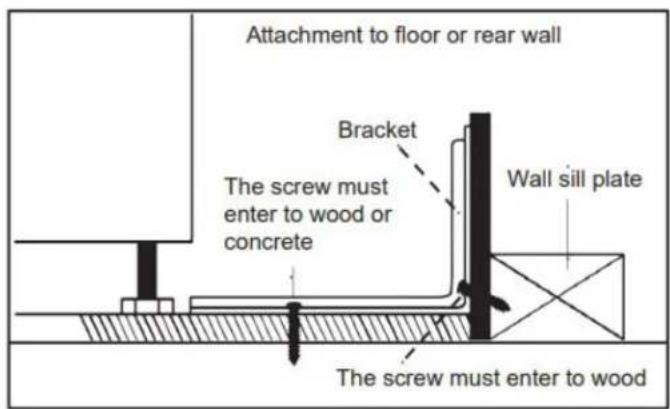
Securing Bracket
The bracket must be screwed to either the FLOOR or REAR WALL.
Floor Installation
- Wood Floor: use the screws provided to secure the bracket using the pair of marked holes (either Loc A or B).
- Concrete floor: Using a concrete drill bit, drill a 5/32 inch (0.4 cm) pilot hole 2 inches (5 cm) deep into the concrete at the center of each of the marked holes (either Loc A or B). Use the screws provided to secure the bracket into the floor.
Rear Wall Installation
Use the 2 screws provided to secure the bracket using the pair of marked holes at Loc C. The screws MUST enter a wood sill plate. If the wall contains any metal studs or similar materials, then the floor must be used.
Checking Bracket
After installing the bracket, slide the range into its final location. The rear leveling leg must be fully inserted into the ANTI-TIP bracket as shown below. To check if the bracket is installed and engaged properly, look underneath the range to see that the leveling leg is engaged in the bracket. On some models, the storage drawer or kick plate can be removed for easier inspection. If visual inspection is not possible, slide the range forward, confirm the anti-tip bracket is securely attached to the floor or wall, and slide the range back so the leveling leg is under the anti-tip bracket. If the range is pull from the wall for any reason, always repeat this procedure to verify the range is properly secured by the anti-tip bracket.
NOTE: The anti-tip bracket must be PROPERLY INSTALLED, and the rear leveling leg must be FULLY ENGAGED into the bracket to prevent the range from tipping. NEVER remove the leveling legs as this will prevent the range from being secured to the ANTI-TIP bracket properly.
INSTALLATION INSTRUCTIONS
INSTALLING RANGE
NOTE: If the range is moved to adjust the leveling legs, ensure that when the range is moved back into the final location that the anti-tip bracket is engaged by repeating steps 1 through 9.
- Slide range into final location, making sure rear leveling leg slides into ant-tip bracket. Leave a 1 inch (2.5cm) gap between the back of the range and the back wall.
- Place the outside of your foot against the bottom front to keep the range from moving and then grasp the back of the range, as shown.
- Slowly attempt to tilt the range forward. If you encounter immediate resistance, the range foot is engaged in the anti-tip bracket. Go to Step 8.
- If the rear of the range lifts more than 1/2 inch (1.3cm) off the floor without resistance, stop tilting the range and lower it gently back to the floor. The range foot is not engaged in the anti-tip bracket.
NOTE: If there is a snapping or popping sound when lifting the range, the range may not be fully engaged in the bracket. Check to see if there are obstructions keeping the range from sliding to the wall or keeping the range foot from sliding into the bracket. Verify that the bracket is held securely in place by the mounting screws.

natural_image
Line drawing of a person leaning against the side of a refrigerator (no text or symbols)- Slide the range forward and verify that the anti-tip bracket is securely attached to the floor or wall.
- Slide the range back so the rear range foot is inserted into the slot of the anti-tip bracket.
- Repeat steps 1 through 3 to ensure that the range foot is engaged in the anti-tip bracket. If the rear of the range lifts more than 1/2 inch (1.3cm) off the floor without resistance, the anti-tip bracket may not be installed correctly. Do not operate the range without anti-tip bracket installed and engaged.
- Move the range into its final location. Check that the range is level by placing a level on the oven bottom.
NOTE: The range must be level for optimum cooking and baking performance.
- If needed, use a wrench to adjust the height of the leveling legs until the range is level from side to side and back to back.
OPERATING INSTRUCTIONS
ACCESSORIES
- Backsplash
- M4*8 Screw for backsplash installation x5
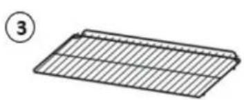
- Racks x2
- Anti-Tip Bracket
- M5*45 Screw for anti-tip bracket x2

natural_image
Simple line drawing of a rectangular grid structure with no text or symbols


OPERATING INSTRUCTIONS
DIMENSIONS
The dimensions of this appliance are:
A. 37.9 \~ 37.12 inches (96.3 \~ 94.3 cm) from the floor to the top of the cooktop (with backsplash installed).
B. 27.6 inches (70 cm) deep
C. 29.9 inches (76 cm) wide
It is the installer's responsibility to comply with installation clearances specified in the manual. The minimum cabinet opening dimensions and clearances must be used. The minimum spacings must be maintained between the appliance cooking surface and the horizontal surface above the cooktop.
30 inches (65 cm) is the minimum clearance between the top of the cooking surface and the bottom of an unprotected wood or metal cabinet.
natural_image
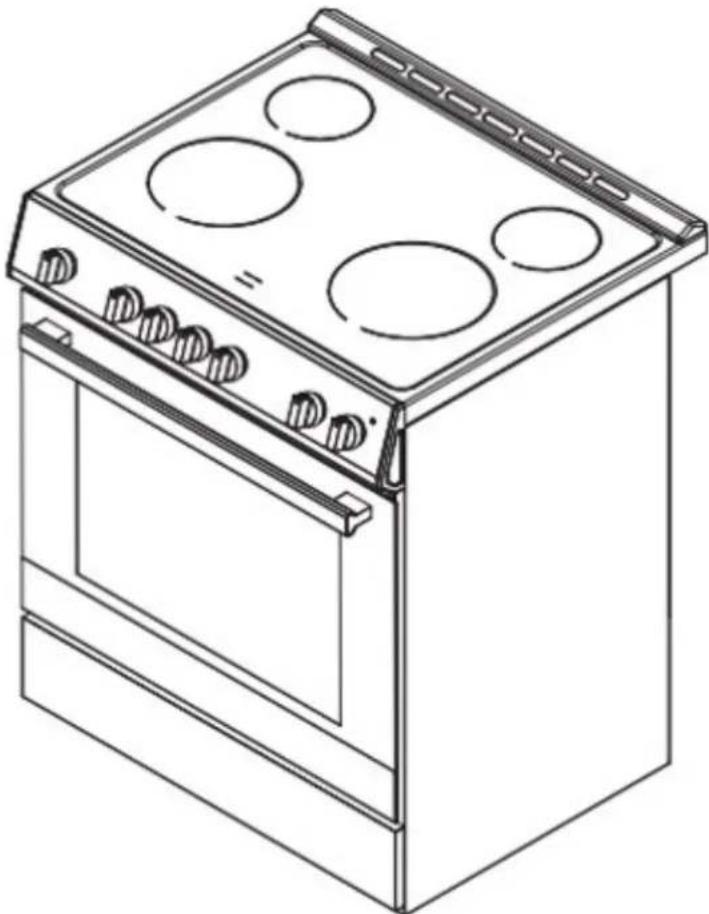
Line drawing of a standard electrical stove with four burners and top cabin (no text or symbols)LEVELING INSTRUCTIONS
The appliance must be level to operate safely and properly. There are four leveling legs located at the corners of the bottom of the appliance. Adjust the leveling legs until the appliance is level. Use a carpenter's level to confirm.

natural_image
Technical line drawing of a mechanical assembly with a gear mechanism and rotational arrow (no text or symbols)OPERATING INSTRUCTIONS
EXTERIOR PARTS INTERIOR PARTS


| 1 | Left Rear Burner 1200W |
| 2 | Left Front Burner 2200W |
| 3 | Control Panel |
| 4 | Anti-tip Bracket |
| 5 | Drawer |
| 6 | Right Rear Burner 1200W |
| 7 | Right Front Burner 2500W |
| 8 | Hot Surface Indicator Lights |
| 9 | Oven Door Window |
| 10 | Oven Vent |
| 11 | Broil Element |
| 12 | Door Gasket |
| 13 | Bottom Element (not visible) |
| 14 | Oven Light |
OPERATING INSTRUCTIONS
CONTROL PANEL

A. Timer Knob 1. Oven Power
B. Front Left Burner 2. Light
C. Rear Left Burner 3. Broil
D. Rear Right Burner 4. Bake
E. Front Right Burner 5. Roast
F. Oven Settings
G. Temperature
H. Light Indicator
Operation of Oven
- Ensure that the shelves are inserted at the correct height.
- Select the desired oven mode.
- Set the oven to the desired preheat temperature.
- Set the timer to activate and preheat the oven (time as necessary)
- Once the preheat indicator light (H) extinguishes, place bakeware with food on one or both of the selves provided with the oven.
- Close the door
- Reset the time for the desired cook time.
NOTE: The timer affects the operation of the oven, if the timer is in OFF, the oven will not work.
NOTE: Do not place anything, including dishes, foil and oven trays on the bottom of the oven when it is in operation to avoid damaging the enamel finish.
NOTE: The interior oven light remains on in all modes. When not in an operational mode, the interior oven light is off.
OPERATING INSTRUCTIONS
This oven combines the functions of traditional oven modes with the functions of modern, fan-assisted convection modes in a single oven. Use the Oven Settings knob to select the oven mode.
NOTE: To maintain oven temperature, limit door openings during cooking.
Timer
The timer will need to be set when you use the unit for the first time, otherwise the oven will not work. The timer knob is used to set an audible tone when the set amount of time has passed. The timer does not affect the cooktop however, it turns the oven on and off. When the countdown ends, the oven will stop however, the oven light will remain on. The light must be turned off using the oven function and temperature control knob.
Oven Settings and Temperatures
There are 4 oven settings and 8 temperature setting to select from as shown in the tables below.
| [WKBW] | Light Broil |  | |
| [HBCG] | Roast Bake | [28T7] |
Temperature Settings
| 1 | 150°F (66°C) | 5 | 350°F (177°C) |
| 2 | 200°F (93°C) | 6 | 400°F (204°C) |
| 3 | 250°F (121°C) | 7 | 450°F (232°C) |
| 4 | 300°F (149°C) | 8 | Max (500°F/260°C) |
OPERATING INSTRUCTIONS
PREHEATING
- Turn the cooking functions knob to the desired function.
- Rotate the Temperature knob to the desired temperature.
NOTE: The higher the temperature selected, the longer it will take to preheat. The actual oven temperature will go higher than your set temperature to offset the heat lost when you open the oven door to place the food on the rack. This ensures that cooking will begin at the proper temperature. Do not open the door while the oven is preheating. When the oven has reached the set temperature, the indicator light on the control panel will turn off. The door can then be opened and food placed into the oven.
BAKE
Baking is cooking with heated air. Both elements in the oven are used. Follow the recipe or food direction for baking temperature, time, and rack position. The temperature can be set from 150^ F ( 66^ C) to MAX.
- Use one rack when selecting the bake mode.
- Occasionally check the oven to see if the food is cooked.
- Use metal bakeware (with or without non-stick finish), heatproof glass, glass ceramic, potter, or other utensils suitable for the oven.
- Leave at least 1-1.5 inches (2.5-4cm) of space between the bakeware and oven walls.
- Do not use aluminum foil or disposable aluminum trays to line any part of the oven as it will alter the cooking performance and can damage the finish of the oven.
- If required a baking tray can be lined with foil and used on the bottom shelf.
- Avoid using the opened door as a shelf to place pans.
BROIL
Broiling uses direct radiant heat to cook food. Only the upper element in the oven is used. Thicker cuts and unevenly shaped meat, fish and poultry may cook better at lower broiling temperatures. For best results, use the two piece broiler pan with grid. It is designed to drain juices which helps to avoid spills and platters. Do not cover the grid with foil. The bottom of the pan may be lined with aluminum foil for easier cleaning.
- Place rack in required position before turning on the oven.
- Select temperature.
- Pull out oven rack to stop position before turning or removing food.
- Do not preheat the oven.
- Turn meats once halfway through the cooking time.
NOTE: The oven door remains closed during broil. When inspecting the food, open the oven door no more than two inches.
OPERATING INSTRUCTIONS
ROAST
When roasting set the desired temperature as shown below. Only the lower element is used. The oven can be preheated before placing the food into the oven.
- Turn the cooking functions knob to Roast.
- Rotate the temperature dial to the desired temperature.
- Open the door and place the food into the oven
Guidelines
- Roast in a low-sided, uncovered pan.
- Use a 2-piece broil pan for roasting uncovered.
- It is recommend to use a probe or meat thermometer to determine the internal doneness of the meat.
- Large poultry may need to be covered with foil during a portion of the roasting time to prevent over browning.
COOKTOP
The ceramic cooking area will glow red when a heating element is on. Some parts of the cooktop may not glow red when an element is on. This is normal. The cooking area cycles on and off, even when set to HI, to keep the cooktop glass from overheating. It is normal for the surface of the ceramic glass to appear to change color when surface cooking areas are hot. As the glass cools, it will return to its original color.
- Make sure the bottoms of pots and pans are clean and dry before using them. Residue and water can leave deposits when heated.
- Avoid storing jars or cans above the cooktop. Dropping a heavy or had object onto the cooktop could crack the cooktop.
- To avoid damage to the cooktop, do not leave a hot lid on the cooktop. As the cooktop cools, air can become trapped between the lid and the cooktop. This could cause the ceramic glass to break when the lid is removed.
- For foods containing sugar in any form, clean up all spills as soon as possible. If sugary spills are allowed to cool down, they can adhere to the cooktop and cause pitting and permanent marks.
- Do not slide cookware or bakeware across the cooktop. Aluminum or copper bottoms and rough finishes on cookware or bakeware could leave scratches or marks on the cooktop.
- Do not cook popcorn in prepackaged aluminum containers on the cooktop. They could leave aluminum marks that cannot be completely removed.
- Do not allow objects that could melt, such as plastic or aluminum foil, to touch any part of the entire cooktop.
- Do not use the cooktop as a cutting board.
- Do not cook foods directly on the cooktop.
NOTE: Clean the cooktop after each use to avoid permanent damage from pitting or scratching to the cooktop surface.
OPERATING INSTRUCTIONS
COOKTOP
Cooking Rings
The general rule of thumb with cookware, the diameter of the cookware should match the diameter of the elements that are being used. If the cookware is small than the element by 1 inch (2.5cm), it will still be effective. Anything that is over 1 inch (2.5cm), will not be effective.
Cookware Characteristics
- Aluminum: heats and cools quickly. May leave metal markings on glass.
- Cast Iron: heats and cools slowly, retains heat and cooks evenly.
• Copper: tin heats and cools quickly. - Enamel cookware: not recommended. Imperfections in enamel may scratch cooktop.
- Glass Ceramic: not recommended. Imperfections in finish may scratch cooktop.
• Stainless Steel: heats and cools moderately.
Heating Zone
- Turn the control knob to the desired position. Heat intensity goes from LOW on the right to HIGH on the left.
- Adjustment is continuous so the cooking zone will operate at any intermediate setting between low and high.
- Once the cooking zone is hot, the LED corresponding to the zone illuminates.
- To switch off the cooking zone, turn the knob in either direction to the "OFF" position.
- The residual heat warning light remains illuminated when the temperature of the ceramic glass surface is hot and will switch off once the surface temperature has cooled.
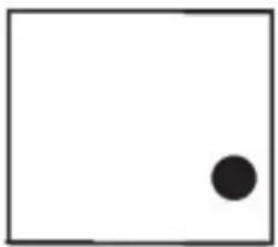
natural_image
Simple black dot centered within a white square border (no text or symbols)The "red circle" will indicate which cooking element is actively hot.
Hot Surface Indicator Light
On ceramic glass cooktops, the Hot Surface Indicator lights are located on the glass cooktop. The Hot Surface Indicator lights will glow as long as any cooking area is too hot to touch, even after the surface cooking area is turned off.
CARE & MAINTENANCE
CLEANING
Before cleaning, make sure all controls are turned off, and the oven and cooktop are cool. Always follow label instruction on cleaning products. It is recommended that soap, water and a soft cloth or sponge is used first unless otherwise noted. Do not use abrasive cleaning products.
Exterior Porcelain Enamel Surfaces
Food spills containing acids, such as vinegar and tomato, should be cleaned as soon as the entire appliance is cool. These spills may affect the finish.
Use glass cleaner, mild liquid cleaner or nonabrasive scrubbing pad. Gently clean around the model and serial number plate as scrubbing may remove numbers.
Exterior Stainless Steel
Use liquid detergent or all-purpose cleaner. Rinse well with clean water and dry soft, lint-free cloth. Stainless Steel Cleaner and Polish Vinegar can be used for hard water spots.
NOTE: Do not use soap-filled scouring pads, abrasive cleaners, cooktop polishing cream, steel-wool pads, gritty washcloths or some paper towels. Damage may occur even with one-time or limited use. Rub in direction of grain to avoid damaging.
Oven Door Exterior
Use glass cleaner and paper towels or nonabrasive plastic scrubbing pad. Apply glass cleaner to soft cloth or sponge, not directly on panel.
Smudges from Aluminum Bottom Pans
Use a cloth dampened in vinegar.
Ceramic Glass Cooktop
To avoid damaging the cooktop, do not use steel wool, abrasive powder cleansers, chlorine bleach, rust remover or ammonia. Ceramic cooktop cleaning materials include cooktop cleaner, cooktop scraper and cooktop cleaning pads available at most grocery stores.
-
Remove food/residue with a cooktop scraper.
-
For best results, use the cooktop scraper while the cooktop is still warm but not hot to the touch.
- It is recommended to wear an oven mitt while scraping the warm cooktop.
- Hold the cooktop scraper at approximately a 45^ angle against the glass surface and scrape the residue. It will be necessary to apply pressure in order to remove the residue.
-
Allow the cooktop to cool down completely before proceeding to Step 2.
-
Apply a few dime-sized drops of cooktop cleaner to the affected areas.
-
Rub cooktop cleaner onto the cooktop surface with a nylon or similar cooktop cleaning pad. Some pressure is needed to remove stubborn stains.
-
Allow the cleaner to dry to a white haze before proceeding to Step 3.
-
Polish with a clean, dry cloth or a clean, dry paper towel.
Cooktop Control Knobs
Use soap and water or dishwasher detergent.
- Pull knobs straight out from the control panel to remove.
- When replacing knobs, make sure knobs are turned to the Off position.
NOTE: Do not use steel-wool, abrasive cleansers or oven cleaner. Do not soak knobs.
CARE & MAINTENANCE
Oven Cavity
Food spills should be cleaned when oven cools. At high temperatures, foods react with porcelain so staining, etching, pitting or faint white spots can result.
Use mild detergent and warm water.
NOTE: Do not use oven cleaners.
Oven Racks
Use a steel-wool pad.
Control Panel
Clean using a glass cleaner and soft cloth or sponge. Apply glass cleaner to soft cloth or sponge, not directly on the panel.
NOTE: Do not use abrasive cleaners, steel-wool pads, gritty washcloths or some paper towels as damage may occur.
Oven Door Removal
For normal oven use, there is no need to remove the oven door. However, should it become necessary, please follow the instructions below.
NOTE:
• Make sure the oven is cool and power to the oven has been turned off before removing the door.
- The oven door is heavy and fragile as well as the door front is glass. To avoid oven door glass breakage, use both hands and grasp on the sides of the oven door to remove.
- Be sure both levers are securely in place before removing the door.
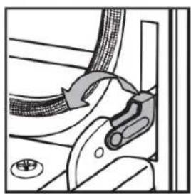
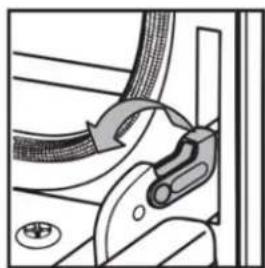
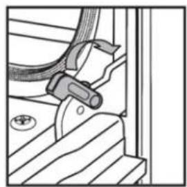
Door removal
- Open the oven door completely.
- Lift up the hinge latch on each side.

natural_image
Diagram of a mechanical component with a clamping tool and directional arrow (no text or symbols)Left hinge
natural_image
Mechanical diagram showing a clamping mechanism with rope and nut components (no text or symbols)Right hinge
- Close the oven door as far as it will shut.
- While grasping both outside edges of the door, lift up on the door.
- Continue to push the top of the door closed while pulling the bottom of the door out of the hinge receivers in the door frame.

natural_image
Illustration of hands using a tool to adjust or install a component, with a downward arrow indicating motion (no text or symbols present)CARE & MAINTENANCE
Door Reinstallation
- Insert both hanger arms into the hinge receivers in the door frame.
- Slowly open the oven door and you will feel the door set into place.
- Move the hinge latches back into the locked position.

natural_image
Technical line drawing of a mechanical assembly with no visible text or symbolsLeft hinge

natural_image
Technical line drawing of a mechanical assembly with no visible text or symbolsRight hinge
- Check that the door opens and closes freely. If it does not, repeat door removal and reinstallation.
Replacing Oven Light
The oven light is a standard 25-watt (G) appliance bulb.
NOTE:
• Make sure the oven and lights are cool and power to the oven has been turned off.
- The lenses must be in place when using the oven. The lenses serve to protect the light bulb from breaking.
- The lenses are made of glass. Handle carefully to avoid breakage.
- Failure to do so could result in death, electrical shock, cuts or burns.
- Disconnect the power.
- Remove the bulb by turning it anti-clockwise.
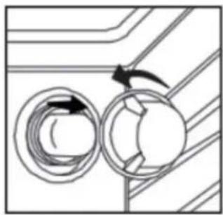
natural_image
Diagram of a mechanical or electrical component with two circular components and directional arrows indicating rotation (no text or symbols)- Remove the burned-out bulb from the socket.
NOTE: To avoid damage or decreasing the life of the new bulb, do not touch the bulb with bare fingers. Wear gloves or use a tissue when replacing the light bulb.
- Replace the bulb and then replace the bulb cover.
- Reconnect the power.
TROUBLESHOOTING
No power
- A fuse may be blown or the circuit breaker tripped
- Plug not fully inserted into the wall outlet
Cooktop elements not working properly
- Improper cookware is being used
- No power
- Heating elements cycle off even when turned to highest setting: temperature limiters are temporarily shutting off the elements due to exceeding the maximum allowable temperature
- Glass ceramic surface is see through or appears to be red in colour: Under direct or bright lighting it may be possible to see through the glass and it may have a red tint. This is normal
Cooling fan continues to run after oven is turned off
• Electronic components have not yet cooled sufficiently
Oven light
- Not working properly: Bulb is loose or burned out
- Stays on: door is not closing completely
- Cannot remove lens cover: Soil build-up around the lens cover
LIMITED "IN HOME" WARRANTY
This quality product is warranted to be free from manufacturer's defects in material and workmanship, provided that the unit is used under the normal operating conditions intended by the manufacturer.
This warranty is available only to the person to whom the unit was originally sold by Danby Products Limited (Canada) or Danby Products Inc. (U.S.A.) (hereafter "Danby") or by an authorized distributor of Danby, and is non-transferable.
TERMS OF WARRANTY
Plastic parts are warranted for thirty (30) days from the date of purchase, with no extensions provided.
First 24 months During the first twenty four (24) months, any functional parts of this product found to be defective, will be repaired or replaced, at warrantor's option, at no charge to the original purchaser.
To obtain service Contact the dealer where the unit was purchased, or contact the nearest authorized Danby service depot, where service must be performed by a qualified service technician. If service is performed on the unit by anyone other than an authorized service depot, all obligations of Danby under this warranty shall be void.
Boundaries of in-home service Danby reserves the right to limit the boundaries of "In Home Service" to the proximity of an authorized service depot. Any appliance requiring service outside the limited boundaries of "In Home Service", will be the consumer's responsibility to transport at their own expense to the original point of purchase or a service depot for repair. If the appliance is installed in a location that is 100 kilometers (62 miles) or more from the nearest service center, it must be delivered to the nearest authorized Danby Service Depot by the purchaser.
Transportation charges to and from the service location are not protected by this warranty and are the responsibility of the purchaser.
Nothing within this warranty shall imply that Danby will be responsible or liable for any spoilage or damage to food or other contents of this appliance, whether due to any defect of the appliance, or its use, whether proper or improper.
EXCLUSIONS
Save as herein provided, by Danby, there are no other warranties, conditions, representations or guarantees, express or implied, made or intended by Danby or its authorized distributors and all other warranties, conditions, representations or guarantees, including any warranties, conditions, representations or guarantees under any Sale of Goods Act or like legislation or statute is hereby expressly excluded. Save as herein provided, Danby shall not be responsible for any damages to persons or property, including the unit itself, howsoever caused or any consequential damages arising from the malfunction of the unit and by the purchase of the unit, the purchaser does hereby agree to indemnify and hold harmless Danby from any claim for damages to persons or property caused by the unit.
GENERAL PROVISIONS
No warranty or insurance herein contained or set out shall apply when damage or repair is caused by any of the following:
1) Power failure.
2) Damage in transit or when moving the appliance.
3) Improper power supply such as low voltage, defective house wiring or inadequate fuses.
4) Accident, alteration, abuse or misuse of the appliance such as inadequate air circulation in the room or abnormal operating conditions (i.e. extremely high or low room temperature).
5) Use for commercial or industrial purposes (i.e. If the appliance is not installed in a domestic residence).
6) Fire, water damage, theft, war, riot, hostility, acts of God such as hurricanes, floods etc.
7) Service calls resulting in customer education.
8) Improper Installation (i.e. Building-in of a free standing appliance or using an appliance outdoors that is not approved for outdoor application, including but not limited to: garages, patios, porches or anywhere that is not properly insulated or climate controlled).
Proof of purchase date will be required for warranty claims; retain bills of sale. In the event that warranty service is required, present the proof of purchase to our authorized service depot.
Warranty Service
In Home
Danby Products Limited
PO Box 1778, Guelph, Ontario, Canada NIH 629
Telephone: (519) 837-0920 FAX: (519) 837-0449
1-800-263-2629
04/17
Danby Products Inc
PO Box 669, Findlay, Ohio, U.S.A. 45840
Telephone: (419) 425-8627 FAX: (419) 425-8629

natural_image
Technical line drawing of a multi-level electric oven or control unit with mounting holes and ventilation ducts (no text or symbols)natural_image
Line drawing of a person leaning against the side of a refrigerator (no text or symbols)natural_image
Line drawing of a standard electrical stove with four burners and top cabin (no text or symbols)natural_image
Technical line drawing of a mechanical assembly with gear and housing components (no text or symbols)
| Luz Asar | |||
 | Asado Hornear |
natural_image
Simple black dot centered within a white square border (no text or symbols)natural_image
Diagram of a mechanical component with a clamping tool and directional arrow (no text or symbols)Bisagra izquierda
natural_image
Mechanical assembly diagram showing a clamping mechanism with no visible text or symbolsBisagra derecha
natural_image
Illustration of hands using a tool to remove or remove a textured material from a tray (no text or symbols)natural_image
Technical line drawing of a mechanical assembly with no visible text or symbolsBisagra izquierda
natural_image
Technical line drawing of a mechanical assembly with no visible text or symbolsBisagra derecha
natural_image
Diagram showing two circular components rotating around a central circular element, with directional arrows indicating rotation (no text or symbols)- Retire la bombilla fundida del casquillo.
NOTA:
Danby Products Limited
PO Box 1778, Guelph, Ontario, Canada N1H 6Z9
Telephone: (519) 837-0920 FAX: (519) 837-0449
1-800-263-2629
04/17
Danby Products Inc.
PO Box 669, Findlay, Ohio, U.S.A. 45840
Telephone: (419) 425-8627 FAX: (419) 425-8629
NOTAS / NOTES :
NOTAS / NOTES :
Danby Products Limited, Guelph, Ontario, Canada N1H 6Z9 Danby Products Inc. Findlay, Ohio, U.S.A. 45840
www.danby.com

- ESTUFA ELÉCTRICA 30"
- Welcome to the Danby family.
- Need Help?
- Important Safety Information READ AND FOLLOW ALL SAFETY INSTRUCTIONS
- WARNING - TIP OVER HAZARD
- ANTI-TIP DEVICE
- WARNING
- SUFFOCATION AND RISK OF CHILD ENTRAPMENT
- SAVE THESE INSTRUCTIONS!
- Important Safety Information
- READ AND FOLLOW ALL SAFETY INSTRUCTIONS
- NOTICE - BEFORE FIRST TIME USE OVEN
- NOTICE - BEFORE FIRST TIME USE COOKTOP
- NOTES:
- AREAS NEAR THEM
- DANGER - GREASE FIRES
- DANGER - FIRE RISKDO NOT TO
- GENERAL SAFETY REQUIREMENTS
- COOKTOP SAFETY REQUIREMENTS
- OVEN SAFETY REQUIREMENTS
- GROUNDING INSTRUCTIONS
- INSTALLATION INSTRUCTIONS
- Installation Measurements
- BACKSPLASH INSTALLATION:
- Power Supply
- IMPORTANT
- CONNECTION TO HOUSE ELECTRICAL SUPPLY
- PARTS NEEDED:
- If using a power supply cord:
- If direct wiring:
- 3-WIRE POWER CABLE INSTALLATION
- 3-WIRE POWER CABLE CONNECTION TO HOUSE ELECTRICAL SUPPLY
- 4-WIRE POWER CABLE INSTALLATION
- 4-WIRE POWER CABLE CONNECTION TO HOUSE ELECTRICAL SUPPLY
- REQUIRED TOOLS
- LOCATION REQUIREMENT
- Ventilation
- Temperature
- ANTI-TIP BRACKET
- Bracket Location
- Securing Bracket
- Floor Installation
- Rear Wall Installation
- Checking Bracket
- INSTALLING RANGE
- OPERATING INSTRUCTIONS
- ACCESSORIES
- DIMENSIONS
- LEVELING INSTRUCTIONS
- CONTROL PANEL
- Operation of Oven
- Timer
- Oven Settings and Temperatures
- PREHEATING
- BAKE
- BROIL
- ROAST
- Guidelines
- COOKTOP
- Cooking Rings
- Cookware Characteristics
- Heating Zone
- Hot Surface Indicator Light
- CARE & MAINTENANCE
- CLEANING
- Exterior Porcelain Enamel Surfaces
- Exterior Stainless Steel
- Oven Door Exterior
- Smudges from Aluminum Bottom Pans
- Ceramic Glass Cooktop
- Cooktop Control Knobs
- Oven Cavity
- Oven Racks
- Oven Door Removal
- NOTE:
- Door removal
- Door Reinstallation
- Replacing Oven Light
- TROUBLESHOOTING
- No power
- Cooktop elements not working properly
- Cooling fan continues to run after oven is turned off
- Oven light
- LIMITED "IN HOME" WARRANTY
- TERMS OF WARRANTY
- EXCLUSIONS
- GENERAL PROVISIONS
- Warranty Service
- In Home
- NOTA:
- 1-800-263-2629
Brand : DANBY
Model : DRRM300BSS
Category : Electric stove