Dockton KKF250C - Faucets Karran - Free user manual and instructions
Find the device manual for free Dockton KKF250C Karran in PDF.

User questions about Dockton KKF250C Karran
0 question about this device. Answer the ones you know or ask your own.
Ask a new question about this device
Download the instructions for your Faucets in PDF format for free! Find your manual Dockton KKF250C - Karran and take your electronic device back in hand. On this page are published all the documents necessary for the use of your device. Dockton KKF250C by Karran.
USER MANUAL Dockton KKF250C Karran
natural_image
Modern stainless steel kitchen faucet with curved handle and side knob (no text or symbols visible)Dockton
Models: KKF250C
KKF250SS
text_image
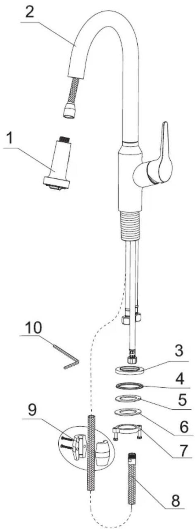
Technical diagram of a kitchen sink with numbered parts for identification| The Component List | Qty. |
| 1. Spray Head | 1 |
| 2. Main Body | 1 |
| 3. Base | 1 |
| 4. Rubber Washer A | 1 |
| 5. Rubber Washer B | 1 |
| 6. Metal Washer | 1 |
| 7. Mounting Hardware | 1 |
| 8. Spray hose | 2 |
| 9. Weight | 1 |
| 10. Hex Wrench | 1 |

text_image
7 11/16" (195 mm) 15° 8 3/16" (208 mm) Ø 1 11/32" ~ Ø 1 1/2" (Ø 34~Ø 38) Hot water Cold water
text_image
15 31/32" (406 mm) Max 1 3/8" (max35 mm)STEP 1
text_image
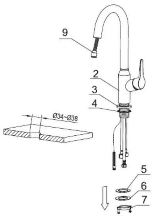
9 2 3 4 Ø34-Ø38 5 6 7- Remove the mounting hardware(7), metal washer(6) and rubber washer B(5) from the main body(2);
STEP 2
text_image
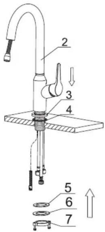
2 3 4 5 6 7- Insert the main body into the hole with the base(3) and rubber washer A(4), refix the rubber washer B(5), metal washer(6) and mounting hardware(7) from the bottom.
STEP 3
text_image
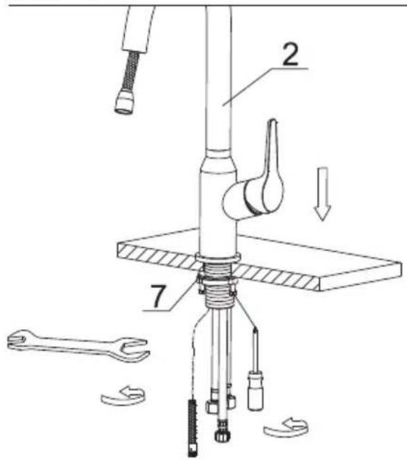
Technical diagram of a mechanical assembly with labeled parts and directional arrows indicating movement or assembly.- After adjusting the direction of the main body(2), tighten the mounting hardware (7) with hands and tighten the screws with a Philips screwdriver.
STEP 4

text_image
1 8 4.- Connect the spray hose(8) and spray head(1) to finish installation.
STEP 5
text_image
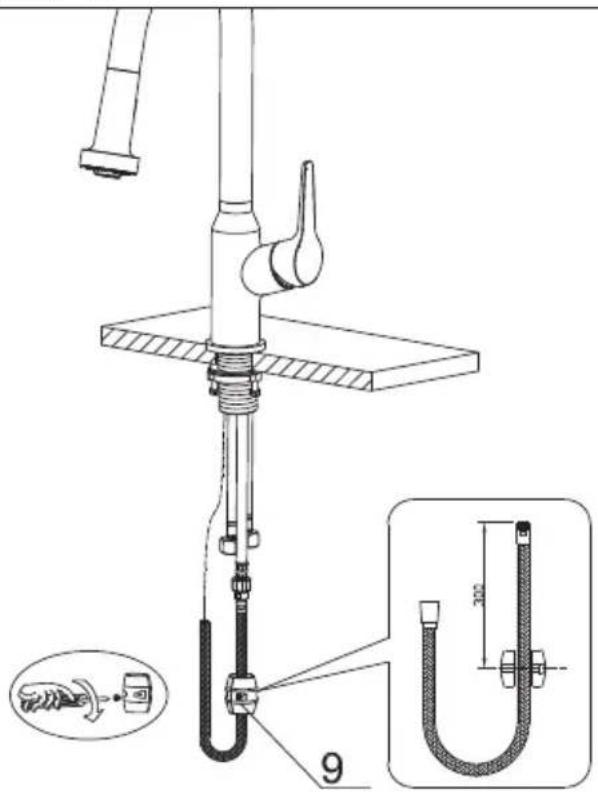
Technical diagram of a U-shaped water tap with labeled components and an inset showing a hand tool and a 300mm dimension.- Attach the weight(9) on the spray hose(8).
STEP 6

text_image
Technical diagram showing a kitchen sink assembly with pipe fittings and a valve, including a close-up of the component being inserted.- Connect the waterlines to outlet tightly. Turn on the outlet and check for leaks.
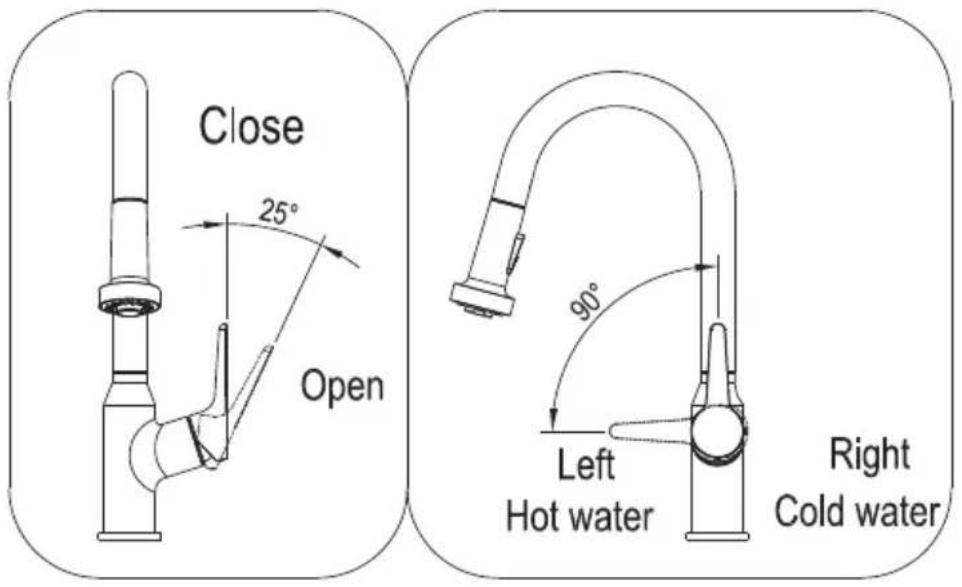
How to operate the handle:
text_image
Close 25° Open 90° Left Hot water Right Cold water1) Open the handle lever to turn water on. Push to turn off.
2) Turn the handle lever to the left to increase hot water flow with higher water temperature, while lower the water temperature by operating reversely.
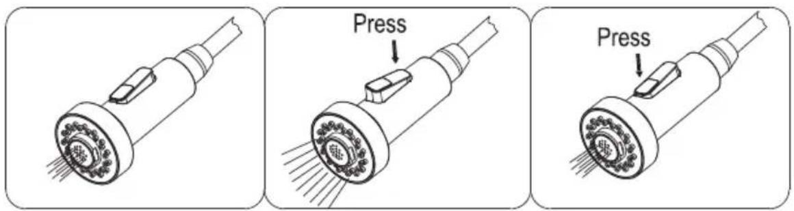
Spray
The operation of the spray diverter:
1) When first turned on, water comes from aerator.
2) Press botton back, water comes from nozzles.
3) Press bottom front, water comes from aerator.
4) Diverter button automatically returns to normal position once handle closed.
text_image
Press Press
text_image
Technical diagram of a laboratory apparatus with numbered components and labeled parts| No. | Description | Finishes/Colors | Item No. |
| 1 | Spray Head | C, SS | 500301912** |
| 2 | Washer | 70020038930 | |
| 3 | Spray Hose | C, SS | 500401611** |
| 4 | Spout Kit | C, SS | 300300386** |
| 5 | Set Screw | 50060039700 | |
| 6 | Main Body | C, SS | 100300518** |
| 7 | 35A Cartridge | 20060010900 | |
| 8 | Nut | 40060199252 | |
| 9 | Cap | C, SS | 500101091** |
| 10 | Hanlde | C, SS | 200100446** |
| 11 | Base | C, SS | 500101638** |
| 12 | Rubber & Metal Washer | 70020037354 | |
| 13 | Mounting Hardware | 40060185018 | |
| 14 | Weight | 50020066700 | |
| 15 | Hot Waterline | 50042068521 | |
| 16 | Cold Waterline | 50042068526 | |
| 17 | Supply Hose | 50040196200 | |
| 18 | Hex Wrench | 50060003700 |
** Denotes faucet component color options:
C - Chrome
SS - Spot Free Stainless Steel