
Tumba KKF230C - Sink Karran - Free user manual and instructions
Find the device manual for free Tumba KKF230C Karran in PDF.

| Product Type | Kitchen Faucet |
| Brand | Karran |
| Model | Tumba KKF230C (also KKF230SS, KKF230MB) |
| Finish Options | Chrome (C), Spot Free Stainless Steel (SS), Matte Black (MB) |
| Material | Brass |
| Installation Type | Deck Mount, Single Hole |
| Spray Function | Pull-down spray with stream/spray diverter |
| Handle Type | Single lever with push-to-turn-off operation |
| Valve/Cartridge | Ceramic disc (35A Cartridge) |
| Spout Height | 16 inches (approx.) |
| Spout Reach | 8.5 inches (approx.) |
| Flow Rate | 1.8 GPM (typical) |
| Number of Holes Required | 1 |
| Weight | 5 lbs (approx.) |
| Warranty | Limited Lifetime Warranty |
| Included Components | Spray head, main body, base, mounting hardware, spray hose, hex wrench |
| Mounting Hardware | Included |
| Color Options | Chrome, Spot Free Stainless Steel, Matte Black |
| Spray Head Type | Pull-down with spray button |
| Compatible with Reverse Osmosis | Yes (with appropriate connections) |
Frequently Asked Questions - Tumba KKF230C Karran
User questions about Tumba KKF230C Karran
0 question about this device. Answer the ones you know or ask your own.
Ask a new question about this device
Download the instructions for your Sink in PDF format for free! Find your manual Tumba KKF230C - Karran and take your electronic device back in hand. On this page are published all the documents necessary for the use of your device. Tumba KKF230C by Karran.
USER MANUAL Tumba KKF230C Karran
natural_image
Modern kitchen faucet with coiled spring and handle (no text or symbols visible)Tumba
Models: KKF230C
KKF230SS
KKF230MB
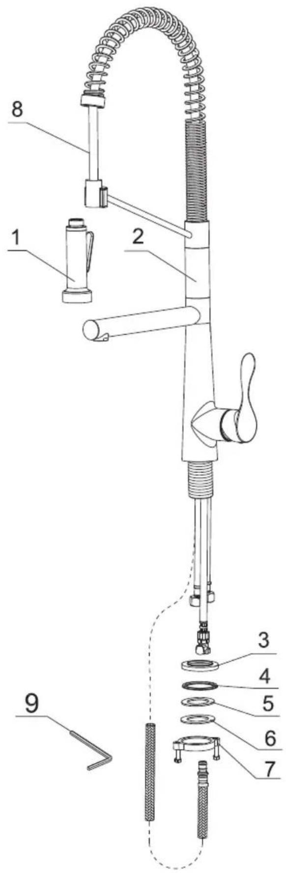
| The Component List | Qty. |
| 1. Spray Head | 1 |
| 2. Main Body | 1 |
| 3. Base | 1 |
| 4. Rubber Washer A | 1 |
| 5. Rubber Washer B | 1 |
| 6. Metal Washer | 1 |
| 7. Mounting Hardware | 1 |
| 8. Spray Hose | 1 |
| 9. Hex Wrench | 1 |

STEP 1
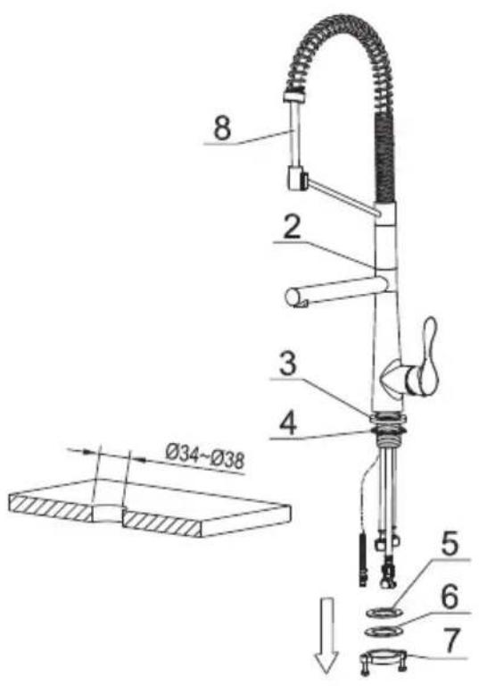
- Remove the mounting hardware(7), metal washer(6) and rubber washer B (5) from the main body (2).
STEP 2

- Insert the main body into the hole with base(3) and rubber washer A(4). Refix the rubber washer B(5), metal washer(6), mounting hardware(7) from the bottom.
STEP 3
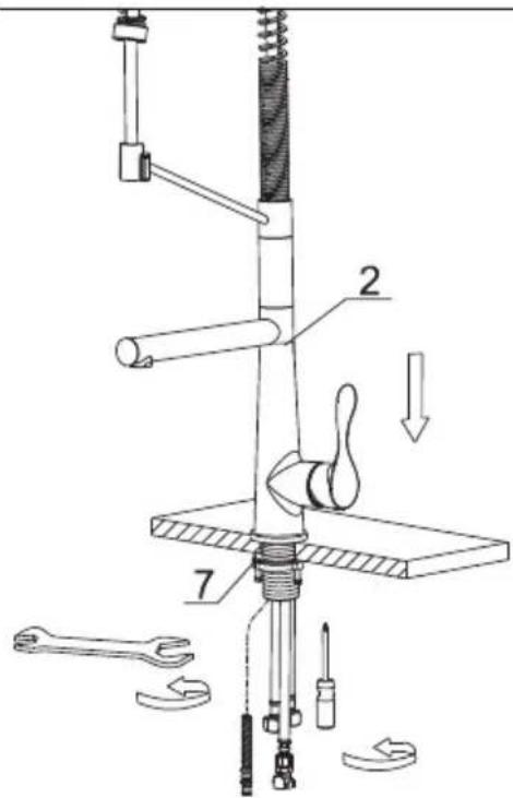
- After adjusting the direction of the main body(2), tighten the mounting hardware (7) with hands and tighten the screws with a Philips screwdriver.
STEP 4

STEP 5
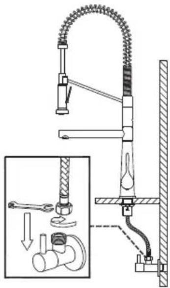
- Connect the waterlines to outlet tightly. Turn on the outlet and check for leaks.
How to operate the handle:

1) Open the handle lever to turn water on. Push to turn off. 2) Turn the handle lever to the left to increase hot water flow with higher water temperature, while lower the water temperature by operating reversely.
Spray
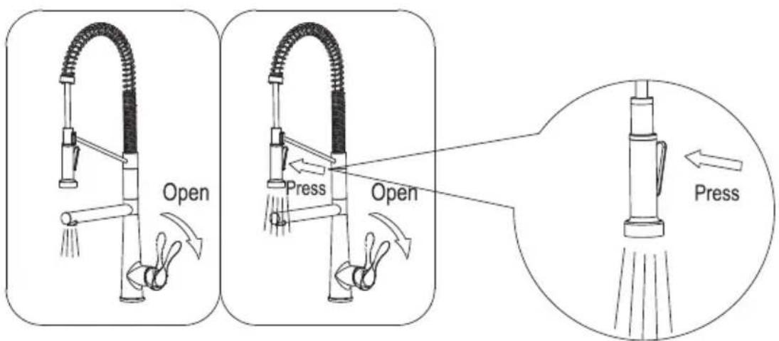
1) When first turned on, water comes from the spout. 2) Water can be diverted from spout to spray by pressing the spray button.
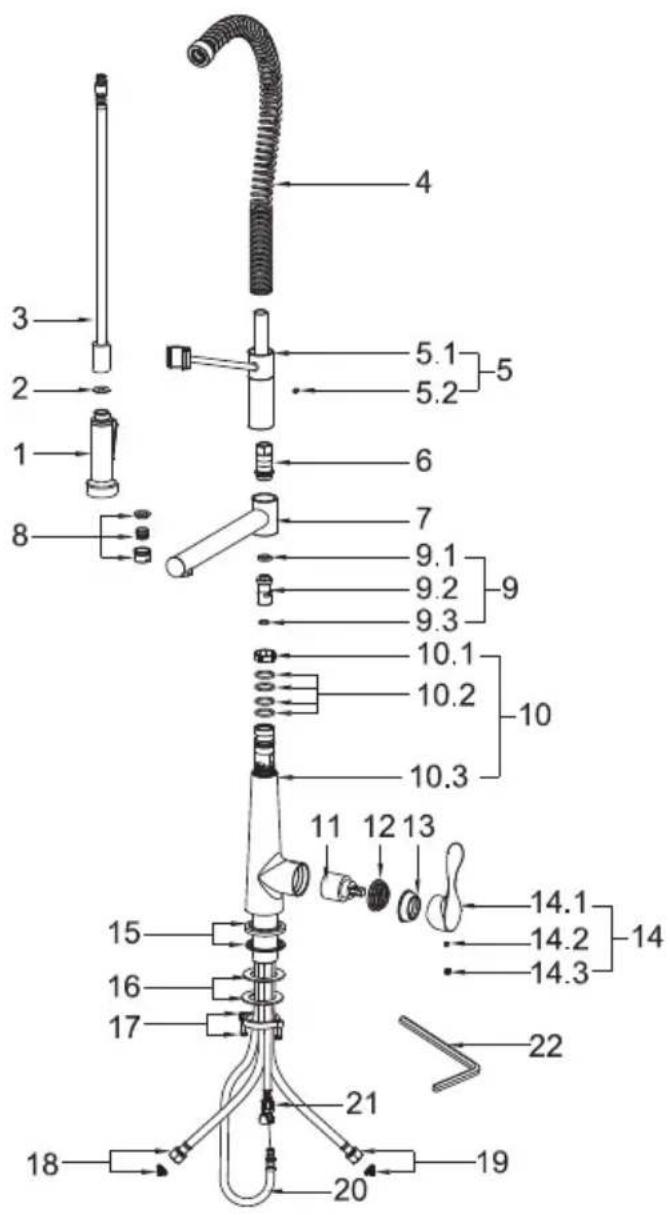
| No. | Description | Finishes/colors | Item No. |
| 1 | Spray Head | C, SS, MB | 500302153** |
| 2 | Washer | 70020038930 | |
| 3 | Spray Hose | C, SS, MB | 500401898** |
| 4 | Spring Assembly | C, SS, MB | 500600409** |
| 5 | Spray Support Assembly | C, SS, MB | 500200992** |
| 6 | Apdater | 40060187752 | |
| 7 | Spout Assembly | C, SS, MB | 300300384** |
| 8 | Aerator Assembly | C, SS, MB | 500500413** |
| 9 | Diverter Assembly | 20070026400 | |
| 10 | Main Body | C, SS, MB | 100300516** |
| 11 | 35A Cartridge | 20060010900 | |
| 12 | Nut | 40060133352 | |
| 13 | Cap | C, SS, MB | 500101091** |
| 14 | Handle | C, SS, MB | 200100409** |
| 15 | Base | C, SS, MB | 500101557** |
| 16 | Rubber & Metal Washer | 70020037354 | |
| 17 | Mounting Hardware | 40060185018 | |
| 18 | Hot Waterline | 50042063821 | |
| 19 | Cold Waterline | 50042063826 | |
| 20 | Spray Hose | 50040196600 | |
| 21 | Supply Hose | 50040131800 | |
| 22 | Hex Wrench | 50060003700 |
** Denotes faucet component color options:
C - Chrome
SS - Spot Free Stainless Steel
MB - Matte Black

