
ELCC-TB-KF-110-1700-0H-P0-CR - Industrial Automation Festo - Free user manual and instructions
Find the device manual for free ELCC-TB-KF-110-1700-0H-P0-CR Festo in PDF.

| Product Type | Electromechanical axis with toothed belt |
| Model | ELCC-TB-KF-110-1700-0H-P0-CR |
| Stroke Length | 1700 mm |
| Max Feed Force | 2500 N |
| Max Driving Torque | 90 Nm |
| Max Speed | 5 m/s |
| Max Acceleration | 30 m/s² |
| Repetition Accuracy | ±0.05 mm |
| Guide Type | Recirculating ball bearing guide |
| Mounting Position | Any |
| Ambient Temperature | -10 °C to +60 °C |
| Degree of Protection | IP20 |
| Max Permissible Force Fy | 20600 N |
| Max Permissible Force Fz | 20000 N |
| Max Permissible Torque Mx | 315 Nm |
| Max Permissible Torque My | 2365 Nm |
| Max Permissible Torque Mz | 2285 Nm |
| Clamping Unit (optional) | Integrated spring-loaded, released by compressed air; static holding force 850 N |
| Lubrication Interval | 2000 to 13000 km depending on load factor |
| Cover Strip Maintenance | Check for wave formation every 2000 km; retension if needed |
| Safety Features | Emergency braking, clamping unit for power failure, hardware limit switches |
| Compliance | EN ISO 13849-1 (clamping unit) |
Frequently Asked Questions - ELCC-TB-KF-110-1700-0H-P0-CR Festo
User questions about ELCC-TB-KF-110-1700-0H-P0-CR Festo
0 question about this device. Answer the ones you know or ask your own.
Ask a new question about this device
Download the instructions for your Industrial Automation in PDF format for free! Find your manual ELCC-TB-KF-110-1700-0H-P0-CR - Festo and take your electronic device back in hand. On this page are published all the documents necessary for the use of your device. ELCC-TB-KF-110-1700-0H-P0-CR by Festo.
USER MANUAL ELCC-TB-KF-110-1700-0H-P0-CR Festo
natural_image
Technical line drawing of a mechanical assembly with mounting flanges and a central circular component (no text or symbols)FESTO
Operating instruction
Translation of the original instructions
Table of contents
1 Applicable documents....4
2 Safety....4
2.1 Safety instructions....4
2.2 Intended use.... 4
2.3 Training of qualified personnel....4
3 Additional information....4
4 Product overview.... 5
4.1 Product design....5
4.2 Function....6
5 Transport....6
6 Assembly....6
6.1 Safety.... 6
6.2 Mounting motor....6
6.3 Mounting axis....7
6.4 Mounting payload on the standard slide....8
6.5 Mounting payload on the additional slide....10
6.6 Mounting end position protection.... 12
6.7 Mounting sensor.... 13
6.8 Connecting sealing air or clamping unit.... 14
7 Commissioning....15
8 Maintenance.... 16
8.1 Safety.... 16
8.2 Checking toothed belt wear.... 16
8.3 Checking cover strip.... 16
8.4 Checking clamping unit.... 17
8.5 Cleaning axis.... 17
8.6 Lubricating axis.... 18
9 Fault clearance.... 19
10 Technical data....22
10.1 Technical data, mechanical....22
10.2 Characteristic curves of deflection.... 24
1 Applicable documents

All available documents for the product → www.festo.com/sp.
2 Safety
2.1 Safety instructions
- Observe the identifications on the product.
-Only use the product if it is in perfect technical condition. - Before working on the product: Switch off the power supply, ensure that it is off and secure it against being switched on again.
- Store the product in a cool, dry environment protected from UV and corrosion. Keep storage times short.
- Store the product in ambient conditions without oils, greases and grease-dissolving vapours.
2.2 Intended use
The axis positions payloads or moves external guides.
The attached clamping unit ELCC-...-C holds payloads in all mounting positions.
The axis is approved for cantilever operation and slide operation.
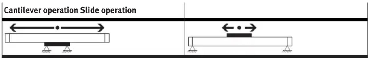
Tab. 1: Operating modes
2.3 Training of qualified personnel
Work on the product may only be carried out by qualified personnel who can evaluate the work and detect dangers. The qualified personnel have knowledge and experience in dealing with electric drive systems.
3 Additional information
- Contact the regional Festo contact if you have technical problems www.festo.com.
-Accessories and spare parts → www.festo.com/catalogue.
4 Product overview
4.1 Product design
Product design ELCC-TB
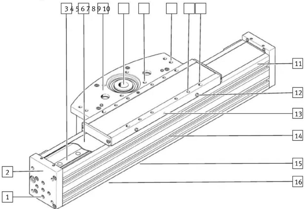
Fig. 1: Product design ELCC-TB
1 Threaded hole and centring hole for payload
2 End cap
3 Guide rail
4 Cover strip
5 Drive head
6 Hollow drive shaft
7 Threaded hole for motor mounting kit
8 Threaded hole for shock absorber stop
9 Threaded hole for direct fastening or threaded hole and centring hole for payload
10 Threaded hole and centring hole for direct fastening or payload
11 Cantilever profile
12 Guide lubrication point
13 Threaded hole for clamping unit connection or sealing air connection
14 Slot for slot nut
15 Threaded hole for sensor bracket
16 Slot for slot nut, payload and switch lug
4.2 Function

natural_image
Mechanical diagram showing a rotating conveyor belt system with gear and motion arrows (no text or labels)Fig. 2: Functional principle of toothed belt drive with fixed toothed belt
The axis converts the rotary motion of the mounted motor into a linear motion of the cantilever or slide. The toothed belt drive converts the torque of the motor into a feed force. The linear movement of the cantilever or slide is accurately guided by the guide. The integrated cover strip prevents abraded particles from penetrating the immediate vicinity of the drive. The clamping unit is used for holding loads at standstill or for emergency braking in the event of a power failure. Sensors and displacement encoder enable query of end positions, reference position and intermediate position.
5 Transport

WARNING
Risk of injury due to falling product
If the product is lifted incorrectly, it may fall and cut, crush or separate body parts.
- Lift the product only with suitable load-bearing equipment.
- Store and transport the product in its original packaging. Observe the weight, the dimensions and the ambient conditions.
-Take the centre of gravity of the product into consideration.
-Store and transport the product in a horizontal position.
6 Assembly
6.1 Safety

WARNING
Risk of Injury due to Unexpected Movement of Components
For vertical or slanted mounting position: when power is off, moving parts can travel or fall uncontrolled into the lower end position.
- Bring moving parts of the product into a safe end position or secure them against falling.
6.2 Mounting motor
i
Observe the limit values for forces, torques and speeds if a non-recommended motor and motor mounting kit are used.
Axial kit EAMM-A

natural_image
Technical line drawing of a mechanical assembly with a central component and mounting base (no text or symbols)Tab. 2: Overview of mounting motors
- Mount the motor and motor mounting kit without tension.
6.3 Mounting axis
| Cantilever operation Slide operation | |||
| Direct fastening on slide Slot nut NST | |||
 |  | ||
Tab. 3: Overview of mounting components
Requirements:
- Adequate clearance for payload to avoid collisions with motor, mounting components and sensor components.
-Sufficient space for maintenance work.
-A mounting surface flatness of 0.01 mm above the slide surface.
Assembly
- Place the mounting components on the support points.
- Tighten the screws. Observe the maximum tightening torque and maximum screw-in depth.
i
When used in multi-axis systems: align to the first axis and install without tension.
| ELCC-TB-... -60 -70 -90 -110 | ||||
| Direct fastening on slide | ||||
| Thread M5 M5 M6 M6 | ||||
| Max. tightening torque [Nm] 6 6 10 24 | ||||
| Max. screw-in depth t_max [mm] 10 10 12 16.2 | ||||
| Centring element [mm] | ∅ 5 H7 | ∅ 9 H7 | ∅ 9 H7 | ∅ 12 H7 |
| Slot nut NST | ||||
| Thread M5 M5 M6 M6 | ||||
| Max. screw-in depth t_max [mm] 6 6 12 12 | ||||
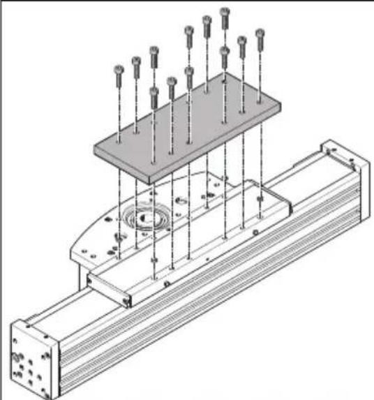
6.4 Mounting payload on the standard slide

WARNING
Unexpected movement of components.
Injury due to impacts or crushing.
- Before working on the product, switch off the control and secure it to prevent it from being switched back on accidentally.

WARNING
Risk of Injury due to Unexpected Movement of Components
For vertical or slanted mounting position: when power is off, moving parts can travel or fall uncontrolled into the lower end position.
- Bring moving parts of the product into a safe end position or secure them against falling.
Assembly
| Cantilever operation Slide operation | |
| Direct fastening on end cap Direct fastening on slide | |
Tab. 4: Mounting payload overview
Requirements:
-Adequate clearance for payload to avoid collisions with motor, mounting components and sensor components.
- Sufficient space for maintenance work.
- A payload mounting surface flatness of 0.01 mm above the slide surface.
-
Minimise the guide load. Short lever arms from the guide centre to the force application points and centres of gravity of the payload.
-
Place centring components in the centring holes.
-
Position the payload at the intended location.
-
For cantilever operation position the payload on the end cap or place it on the profile.
-
For slide operation position the payload on the slide. In the delivery status the centring elements are placed in centring holes.
-
Tighten the screws. Observe the maximum tightening torque and maximum screw-in depth.
| ELCC-TB-... -60 -70 -90 -110 | ||||
| Direct fastening on end cap | ||||
| Thread, inside/outside M4 M4/M5/M6 | M6/M8 M6/M8 | |||
| Max. tightening torque, [Nm] 3 3/ inside/outside | 6/10 10/18 10/18 | |||
| Max. screw-in depth t_max , [mm] 14 inside/outside | 14/15/18 18 18 | |||
| Centring element, inside/ outside | H7 ∅ 7 H7/∅ 9 H7 | ∅ 9 H7 ∅ 9 H7 | ||
| Direct fastening on slide | ||||
| Thread | → 6.3 Mounting axis | |||
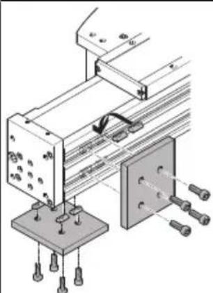
6.5 Mounting payload on the additional slide

WARNING
Unexpected movement of components.
Injury due to impacts or crushing.
- Before working on the product, switch off the control and secure it to prevent it from being switched back on accidentally.

WARNING
Risk of Injury due to Unexpected Movement of Components
For vertical or slanted mounting position: when power is off, moving parts can travel or fall uncontrolled into the lower end position.
- Bring moving parts of the product into a safe end position or secure them against falling.
i
- When using an additional external guide, ensure that the axes and guide are precisely parallel and aligned.
- Recommendation: use guide mountings with tolerance compensation.
Tension due to manufacturing tolerances may be encountered with axes with additional slides when mounting an adapter plate supplied by the customer.
Assembly
natural_image
Isometric technical diagram of a mechanical assembly with rods and supports (no text or symbols)Fig. 3: Mounting payload, example "top mounting"
Requirements:
-A fixed-floating bearing for the carriage connection.
-Use a tolerance compensation in case of height deviation from the standard slide surface.
- Adequate clearance for payload to avoid collisions with motor, mounting components and sensor components.
-Sufficient space for maintenance work.
-A payload mounting surface flatness of 0.01 mm above the slide surfaces.
- Minimise the guide load. Short lever arms from the guide centre to the force application points and centres of gravity of the payload.
1. Place centring components in the centring holes.
2. Mount the adapter plate on the standard slide.
3. Place the tolerance compensation elements on the additional slide.
4. Align and mount the adapter plate on the additional slide.
5. Tighten the screws. Observe the maximum tightening torque and maximum screw-in depth.
| ELCC-TB-...-Z... -60 -70 -90 -110 | ||||
| Direct fastening on slide | ||||
| Thread | → 6.3 Mounting axis | |||
- Check the running behaviour of the slides.
Assembly
6.6 Mounting end position protection

Fig. 4: Mounting shock absorber stop, shock absorber retainer and shock absorber
1 Shock absorber
3 Shock absorber stop
2 Shock absorber retainer
- Mount the shock absorber stop.
- Mount the shock absorber retainer.
- Mount the shock absorber.
Assembly
6.7 Mounting sensor
natural_image
Technical diagram of a mechanical assembly with labeled parts, showing structural components and assembly details (no readable text or symbols)Fig. 5: Mounting switch lug, sensor and sensor bracket
1 Switch lug
3 Sensor
2 Sensor bracket
Requirements:
- Protect the sensor from external magnetic or ferritic influences with min. 10 mm distance from slot nuts.
- Use a hardware limit switch with N/C contact function to guarantee protection in the event of a sensor failure.
-Use an inductive sensor.
- Mount the switch lug.
- If necessary, mount the sensor bracket.
- Mount the sensor.
- If necessary, mount the cable with clips.
- If necessary, mount the slot cover.
6.8 Connecting sealing air or clamping unit
The supply ports of the axis can be used as follows, depending on the product variant:
- Sealing air connection: for axes with strip cover ELCC-...-70/90/110-P9.
- Clamping unit connection: for axes with attached clamping unit ELCC-...-70/90/110-C.
The use of sealing air at approx. ± 0.02 MPa (± 0.2 bar, ± 2.9 psi) reduces or prevents the following contamination:
- The application of negative pressure minimises the release of abraded particles into the environment.
-The application of overpressure reduces the penetration of dirt into the drive train.
T
Always use Loctite 222 to seal an open supply port.
flowchart
graph TD
    A["Servo drive"] --> B["M"]
    B --> C["12 Valve"]
    C --> D["2 Actuator"]
    D --> E["3 Pressure Relief Valve"]
    E --> F["Output"]
    G["UV/W"] --> B
    H["DOUT"] --> B
Fig. 6: Example of control of clamping unit ELCC-...-C
natural_image
Technical line drawing of a mechanical assembly with mounting holes and a central circular component (no text or symbols)Fig. 7: Connecting sealing air or clamping unit
- Remove one plug screw from the threaded hole of the slide or drive head.
- Mount the fitting (M5; 0.5 Nm) and connect the tubing.
7 Commissioning

WARNING
Risk of injury due to unexpected movement of components.
- Protect the positioning range from unwanted intervention.
- Keep foreign objects out of the positioning range.
- Perform commissioning with low dynamic response.
NOTICE
Elasticity of the toothed belt
The elasticity of the toothed belt generates an additional spring effect at high acceleration and deceleration, which can lead to an inadmissible nominal/actual deviation when the slide is moved or when the end position is reached.
- Consider the setpoint deviation determined during the test run during parameterisation of position setpoint values.
i
Block-shaped acceleration profiles without jerk limitation can have the following effects:
- Overshooting effects during positioning.
- Rise of the entire system.
- High mechanical loads on the lead screw due to high force peaks.
Recommendation: reduce high force peaks in the acceleration and deceleration phases by using the jerk limitation.
i
Identical axes can generate different running noises depending on the parameterisation, mode of operation, type of mounting, installation environment and components.
Requirements:
- The motor encoder is referenced to the reference mark by a homing run.
-The motor encoder has the absolute reference to the reference mark.
- The direction of movement of the slide is determined by the direction of rotation of the motor.
- The mounting of the drive system has been checked.
–The protective cover of the cover strip is removed.
–The installation on the motor has been checked.
- There are no foreign objects in the movement space of the drive system.
- Maximum permissible feed force and drive torque as a function of acceleration, deceleration, e.g. with stop function or quick stop, speed, moving mass and mounting position, are not exceeded.
- Axis is not mechanically overloaded and dynamic setpoint deviation is not exceeded as a result of force peaks, torque peaks or overshoot effects, e.g. overrunning the end position.
Overloads and overruns as a result of jerk limitation must be restricted by reduced acceleration and deceleration setpoints or optimised controller settings.
–The software end positions are not within the effective range of the mechanical stops.
-No homing or test run to mechanical end stops.
Maintenance
- Start check run.
- Select permissible reference points "against reference switch" for the homing.
- Start the homing run with reduced speed setpoints, acceleration setpoints and deceleration setpoints.
- Start the test run with reduced speed setpoints, acceleration setpoints and deceleration setpoints.
- Check that the slide completes the entire travel cycle within the specified time.
The slide stops its travel when it reaches a limit switch and the drive system is ready for operation.
8 Maintenance
8.1 Safety

WARNING
Unexpected movement of components.
Injury due to impacts or crushing.
- Before working on the product, switch off the control and secure it to prevent it from being switched back on accidentally.
8.2 Checking toothed belt wear
Checking toothed belt wear
i
The toothed belt is tensioned for its entire service life.
The toothed belt must not be retensioned.
- ELCC-...-PU1:
- Initial check: after 1000 km.
-Periodic check: every 500 km.
ELCC-...-CR/-PU2:
-Initial check: after 5000 km.
- Periodic check: every 1000 km.
- If the toothed belt shows visible wear: send the axis to Festo or contact Festo Service
→ www.festo.com.
8.3 Checking cover strip
- Check the cover strip for wave formation every 2000 km.
- Retension the cover strip as follows if waves are detected.
- Replace the belt reversals and the cover strip if retention is no longer possible.
Retensioning cover strip on both sides with ELCC-...-P9
1 Clamping element
2 Cover strip
3 Screw
4 End cap
Fig. 8: Retensioning cover strip
- Unscrew the screws 3.
- Push the cover strip 2 into the cover 4.
- Tighten the cover strip with a clamping element 1.
- Tighten the screws to 6 Nm ± 10%.
8.4 Checking clamping unit
Clamping unit ELCC-...-C
Check the holding force of the clamping unit at every maintenance interval or after every emergency braking in the event of a power failure.
i
The clamping unit must be replaced after 1000 emergency braking operations or after 50,000 clamping operations → Contact your local Festo service centre.
-Check holding function as follows:
- Move the cantilever or slide to an end position.
- Exhaust the clamping unit connection
- Allow the test force (the test pressure) to act on the drive for at least 5 s. During this time, the cantilever or the slide must not move.
The test force and the tolerance window can be taken from the risk assessment of the application.
8.5 Cleaning axis
Clean the product with a clean, soft cloth and non-abrasive cleaning agents.
Removing abraded particles in the drive head
At every maintenance interval remove the particles from the toothed belt and cover strip wear on the axis or in the drive head as required.
Maintenance
- Press both interlocks (1) simultaneously up to the stop.

- With the interlocks (1) pressed, pull the housing (2) off the drive head.
- Remove abraded particles in the drive head if necessary.
- Insert the housing into the guide of the interlock and push it onto the drive head until the interlocks engage.
8.6 Lubricating axis
Requirements:
Recirculating ball bearing guide
- The pressure grease gun LUB-1, 647958 is available.
-For ELGA-TB-KF: the roller-bearing grease LUB-KC1, 684474 is available. - For ELGA-TB-KF-F1: roller bearing grease Elkalub VP 874 supplied by Chemie-Technik, Vöhringen, is available.
-
The lubrication adapter LUB-1-TR-I, 647959 or LUB-1-TR-L, 647960 is available.
-
Calculate the load comparison factor f_v with formula for combined loads 10.1 Technical data, mechanical.
-
Take the lubrication interval S_int as a function of the load comparison factor f_v from the characteristic curve.
line
| f_v | S_int [km] | | --- | --- | | 0.2 | 13000 | | 0.4 | 12500 | | 0.6 | 11000 | | 0.8 | 8000 | | 1.0 | 2000 |- Determine the load factors:
-Dusty and dirty environment.
- Nominal stroke < 300 mm or > 2000 mm.
- Ambient temperature > +40 °C.
-Operating age > 3 years. - The travel profile matches triangular operation, e.g. frequent acceleration and braking.
Fault clearance
- If there is a load factor, halve the lubrication interval S_int . If there are multiple load factors, reduce the lubrication interval S_int to a quarter of the standard interval.
- If necessary, replace the needle point of the pressure grease gun with the lubrication adapter, axial outlet or radial outlet.
- Press the pressure grease gun on the lubrication nipple of the recirculating ball bearing guide. Press in the roller bearing grease at the front or left and right.
| ELCC-TB-... -60 -70 -90 -110 | ||||
| Grease volume per lubricating hole | [g] 1.7 5 7.5 11.2 |

natural_image
Technical line drawing of a mechanical assembly with a curved component and attached cable (no text or symbols)
natural_image
Technical diagram of a mechanical assembly with two connectors and a central component (no text or symbols)- Move along the complete travel distance during the lubrication process to distribute the grease evenly in the interior.
- If necessary, grease other components with roller bearing grease, e.g. the guide rail.
9 Fault clearance

WARNING
Unexpected movement of components.
Injury due to impacts or crushing.
- Before working on the product, switch off the control and secure it to prevent it from being switched back on accidentally.

WARNING
Risk of Injury due to Unexpected Movement of Components
For vertical or slanted mounting position: when power is off, moving parts can travel or fall uncontrolled into the lower end position.
- Bring moving parts of the product into a safe end position or secure them against falling.

WARNING
Risk of injury due to unexpected movement of components.
- Protect the positioning range from unwanted intervention.
- Keep foreign objects out of the positioning range.
- Perform commissioning with low dynamic response.
| Error description Cause Remedy | ||
| Loud running noises, vibrations or rough running of the axis. | Coupling distance too short. | - Observe the permissible coupling spacings → Assembly instructions of the motor mounting kit. |
| Torsional stresses | - Install axis without tension. Make sure that the contact surface is flat → 6.3 Mounting axis.- Change the layout of the attachment component, e.g. payload.-Align axes parallel to each another. | |
| Current controller settings. | - Optimise controller data, e.g. speed, acceleration, .... | |
| Resonance oscillation of the axis. | - Change travel speed. | |
| Wear on bearing or guide. | - Contact local Festo Service.- Replace axis. | |
| Toothed belt wear. | - Contact local Festo Service.- Replace toothed belt. | |
| Insufficient lubrication of the guide. | - Lubricate the guide → 8.6 Lubricating axis. | |
| Vibrations at the cantilever. Operation at the resonant frequency of the axis. | - Change travel speed.- Change the acceleration.- Increase axis stiffness, e.g. shorter support distances.- Change the payload geometry. | |
| Long cantilever oscillation. Resonant frequency of profile and payload too low. | - Change the payload geometry. | |
| Cantilever or slide does not move. | Coupling slips. | - Check the mounting of the shaft-hub connection → Assembly instructions of the motor mounting kit. |
| Loads are too high. | - Reduce forces and torques. Consider dynamics. | |
| Toothed belt torn. | - Contact local Festo Service.- Replace axis. | |
| Overruns the end position. Sensor does not switch. | - Check sensor, installation and parameterisation. | |
| Idling torque too high. Wear in the drivetrain. | - Contact local Festo Service.- Replace axis. | |
| Toothed belt skips. Toothed belt pretensioning too low. | - Contact local Festo Service.- Replace axis. | |
| - Optimise controller data, e.g. speed, acceleration, ... | ||
| - Reduce travel speed. | ||
| Wave formation on the cover strip or aluminium abrasion on the axis. | Wear on belt reversals. | - Retension cover strip → 8.2 Checking toothed belt wear.- Replace belt reversal and cover strip. |
| Clamping unit does not open. Operating pressure too low. | - Increase operating pressure to the permissible pressure range. | |
| - Contact local Festo Service.- Replace axis. | ||
| Clamping unit does not open. Operating component worn or clamping mechanism defective. | - Contact local Festo Service.- Replace axis. | |
Tab. 5: Overview of fault clearance
10 Technical data
10.1 Technical data, mechanical
| ELCC-TB-... -60 -70 -90 -110 | ||||
| Design Electromechanical axis with toothed belt | ||||
| Guide Recirculating ball bearing guide | ||||
| Mounting position Any | ||||
| Max. feed force [N] 300 600 1200 2500 | ||||
| Max. driving torque [Nm] 5.2 10.4 | 33 | 90 | ||
| Max. idling torque at speed = 0.2 m/s [Nm] 0.6 | 1.2 2.5 4 | |||
| Max. speed [m/s] | 5 | |||
| Max. acceleration [m/s ^2 ] | 50 | 30 | ||
| Repetition accuracy [mm] | ± 0.05 | |||
| Feed constant [mm/rev] | 96 | 96 | 160 216 | |
| Ambient temperature [°C] | -10 ... +60 | |||
| Storage temperature [°C] | -20 ... +80 | |||
| Degree of protection | IP20 | |||
| Max. permissible forces and torques on the slide | ||||
| Fy [N] 4200 | 9600 13900 | 20600 | ||
| Fz [N] 4100 | 9400 13500 | 20000 | ||
| Mx [Nm] 35 | 105 | 165 315 | ||
| My [Nm] 290 | 825 1300 2365 | |||
| Mz [Nm] 285 | 795 1230 2285 | |||
| Distance to guide centre | ||||
| a [mm] | 29.9 | 39.1 | 43.8 | 54 |
| Calculating the load comparison factor | ||||
| fv | fv = |Fy, dyn|Fy, max + |Fz, dyn|Fz, max + |Mx, dyn|Mx, max + |My, dyn|My, max + |Mz, dyn|Mz, max ≤ 1 | |||
 | ||||
Tab. 6: Technical data, mechanical
Technical data for clamping unit ELCC-...-C
| ELCC-TB-...-C -70 -90 -110 | |||
| Clamping unit | |||
| Design clamping unit integrated in the drive | |||
| Clamping type Clamping by spring force, releasing by compressed air | |||
| Effective direction at both ends | |||
| Well-tried component in accordance with EN ISO 13849-1:2015 | |||
| Permissible operating pres- [bar] 4 ... 6.5sure for releasing theclamping unit | |||
| Operating medium Compressed air in accordance with ISO 8573-1:2010 [7:4:4] | |||
| Response time [ms] <100 | |||
| Ambient temperature [°C] -10 ... +60 | |||
| Clamping1) | |||
| Static holding force [N] | 450 | 550 | 850 |
| Max. axial movement caused [mm]by clamping of the clampingunit | 0.2 | ||
| Service-life value B10 with [millionswitching cycles] | 0.05 | ||
| Emergency braking3) | |||
| Max. number of emergency braking operations with energy per emergency [J] 30 braking | 1000 | ||
1) Clamping means that the clamping unit fixes the stationary cantilever at its current position.
2) The general assumption B10d = 2 x B10 is not permissible.
3) Emergency braking means braking of the moving mass, e.g. in case of power failure of the system.
Tab. 7: Technical data for clamping unit ELCC-...-C
10.2 Characteristic curves of deflection
The maximum deflection f of the cantilever as a function of cantilever length A and payload m
Drive head, horizontal, front or rear Drive head, vertical, top or bottom
Tab. 8: Alignment of the drive head
line
| A [mm] | m = 0 kg | m = 5 kg | m = 10 kg | | ------ | -------- | -------- | --------- | | 0 | 0 | 0 | 0 | | 200 | 0 | 0 | 0 | | 400 | 0 | 0 | 0 | | 600 | 0.5 | 0.7 | 1.0 | | 800 | 1.0 | 1.5 | 2.0 | | 1000 | 1.5 | 2.0 | 3.0 | | 1200 | 2.0 | 2.5 | 4.5 | | 1400 | 2.5 | 3.0 | 8.5 |Fig. 9: ELCC-TB-60, horizontal
Technical data

line
| A [mm] | m = 0 kg | m = 5 kg | m = 10 kg | | ------ | -------- | -------- | --------- | | 0 | 0 | 0 | 0 | | 200 | 0 | 0 | 0 | | 400 | 0 | 0 | 0 | | 600 | 0 | 0.2 | 0.3 | | 800 | 0.1 | 0.5 | 1.0 | | 1000 | 0.3 | 1.0 | 2.0 | | 1200 | 0.5 | 2.0 | 4.0 | | 1400 | 0.7 | 3.0 | 5.5 |Fig. 10: ELCC-TB-60, vertical

line
| A[mm] | m = 0 kg | m = 10 kg | m = 20 kg | m = 30 kg | m = 35 kg | |-------|----------|-----------|-----------|-----------|-----------| | 200 | 0.0 | 0.0 | 0.0 | 0.0 | 0.0 | | 400 | 0.5 | 0.7 | 0.9 | 1.1 | 1.3 | | 600 | 1.0 | 1.5 | 2.0 | 2.5 | 3.0 | | 800 | 1.5 | 2.5 | 3.5 | 4.5 | 5.5 | | 1000 | 2.0 | 4.0 | 5.5 | 7.0 | 8.5 | | 1200 | 2.5 | 6.0 | 8.0 | 10.0 | 12.0 | | 1400 | 3.0 | 8.5 | 11.0 | 13.5 | 15.5 | | 1600 | 3.5 | 11.0 | 14.0 | 16.0 | 18.0 |Fig. 11: ELCC-TB-70, horizontal
Technical data

line
| A [mm] | f [mm] (Line 1) | f [mm] (Line 2) | f [mm] (Line 3) | f [mm] (Line 4) | f [mm] (Line 5) | | ------ | --------------- | --------------- | --------------- | --------------- | --------------- | | 0 | 0 | 0 | 0 | 0 | 0 | | 200 | 0 | 0 | 0 | 0 | 0 | | 400 | 0 | 0 | 0 | 0 | 0 | | 600 | 0.5 | 0.6 | 0.7 | 0.8 | 0.9 | | 800 | 1.5 | 1.8 | 2.0 | 2.2 | 2.5 | | 1000 | 3.0 | 3.5 | 4.0 | 4.5 | 5.0 | | 1200 | 5.0 | 5.5 | 6.0 | 6.5 | 7.0 | | 1400 | 7.5 | 8.0 | 8.5 | 9.0 | 9.5 | | 1600 | 12.0 | 12.5 | 13.0 | 13.5 | 14.0 |m = 0 kg
……m = 10 kg
---- m = 20 kg
……m = 30 kg
m = 35 kg
Fig. 12: ELCC-TB-70, vertical

line
| A [mm] | f [mm] (Line 1) | f [mm] (Line 2) | f [mm] (Line 3) | f [mm] (Line 4) | f [mm] (Line 5) | f [mm] (Line 6) | f [mm] (Line 7) | | ------ | --------------- | --------------- | --------------- | --------------- | --------------- | --------------- | --------------- | | 0 | 0 | 0 | 0 | 0 | 0 | 0 | 0 | | 400 | ~0.5 | ~0.6 | ~0.7 | ~0.8 | ~0.9 | ~1.0 | ~1.1 | | 800 | ~1.5 | ~1.8 | ~2.0 | ~2.2 | ~2.4 | ~2.6 | ~2.8 | | 1200 | ~3.0 | ~3.5 | ~3.8 | ~4.0 | ~4.2 | ~4.4 | ~4.6 | | 1600 | ~5.0 | ~5.5 | ~5.8 | ~6.0 | ~6.2 | ~6.4 | ~6.6 | | 2000 | ~7.0 | ~7.5 | ~7.8 | ~8.0 | ~8.2 | ~8.4 | ~8.6 |m = 0 kg
……m = 10 kg
- - - - m = 20 kg
……m = 30 kg
m = 40 kg
m = 50 kg
Fig. 13: ELCC-TB-90, horizontal
Technical data
line
| A [mm] | m = 0 kg | m = 10 kg | m = 20 kg | m = 30 kg | m = 40 kg | m = 50 kg | | ------ | -------- | --------- | --------- | --------- | --------- | --------- | | 0 | 0 | 0 | 0 | 0 | 0 | 0 | | 400 | ~0.5 | ~0.7 | ~0.9 | ~1.1 | ~1.3 | ~1.5 | | 800 | ~1.0 | ~1.5 | ~2.0 | ~2.5 | ~3.0 | ~3.5 | | 1200 | ~1.5 | ~2.5 | ~4.0 | ~5.0 | ~6.0 | ~7.0 | | 1600 | ~2.0 | ~4.0 | ~7.0 | ~9.0 | ~11.0 | ~13.0 | | 2000 | ~2.5 | ~6.0 | ~10.0 | ~12.0 | ~14.0 | ~16.0 |Fig. 14: ELCC-TB-90, vertical
line
| A[mm] | m = 0 kg | m = 20 kg | m = 30 kg | m = 40 kg | m = 50 kg | |-------|----------|-----------|-----------|-----------|-----------| | 0 | 0.0 | 0.0 | 0.0 | 0.0 | 0.0 | | 400 | 0.1 | 0.1 | 0.1 | 0.1 | 0.1 | | 800 | 0.5 | 0.7 | 0.9 | 1.1 | 1.3 | | 1200 | 1.2 | 1.8 | 2.5 | 3.0 | 3.5 | | 1600 | 2.0 | 3.0 | 4.0 | 4.5 | 5.0 | | 2000 | 2.5 | 4.5 | 6.0 | 6.5 | 7.0 |Fig. 15: ELCC-TB-110, horizontal
Technical data
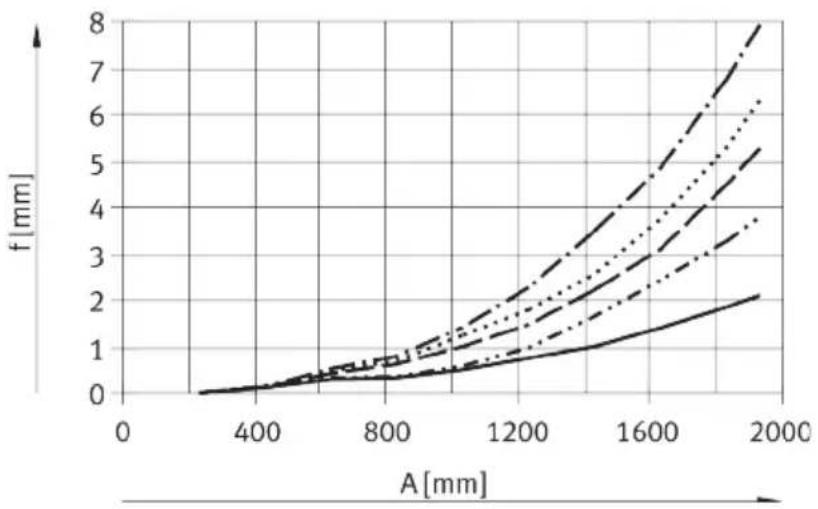
line
| A [mm] | f [mm] (Line 1) | f [mm] (Line 2) | f [mm] (Line 3) | f [mm] (Line 4) | f [mm] (Line 5) | | ------ | --------------- | --------------- | --------------- | --------------- | --------------- | | 0 | 0 | 0 | 0 | 0 | 0 | | 400 | ~0.1 | ~0.1 | ~0.1 | ~0.1 | ~0.1 | | 800 | ~0.5 | ~0.6 | ~0.7 | ~0.8 | ~0.9 | | 1200 | ~1.5 | ~1.8 | ~2.0 | ~2.2 | ~2.5 | | 1600 | ~3.0 | ~3.5 | ~4.0 | ~4.5 | ~5.0 | | 2000 | ~5.0 | ~6.0 | ~7.0 | ~8.0 | ~9.0 |m = 0 kg
……m = 20 kg
- - - - m = 30 kg
……m = 40 kg
m = 50 kg
Fig. 16: ELCC-TB-110, vertical
Copyright:
Festo SE & Co. KG
Ruiter Straße 82
73734 Esslingen
Germany
Phone:
+49 711 347-0
- FESTO
- Table of contents
- Applicable documents....4
- Safety....4
- Additional information....4
- Product overview.... 5
- Transport....6
- Assembly....6
- Commissioning....15
- Maintenance.... 16
- Fault clearance.... 19
- Technical data....22
- Applicable documents
- Safety
- Safety instructions
- Intended use
- Training of qualified personnel
- Additional information
- Product overview
- Product design
- Function
- Transport
- WARNING
- Risk of injury due to falling product
- Assembly
- Safety
- Risk of Injury due to Unexpected Movement of Components
- Mounting motor
- i
- Mounting axis
- Requirements:
- Assembly
- Mounting payload on the standard slide
- Unexpected movement of components.
- Mounting payload on the additional slide
- Mounting end position protection
- Mounting sensor
- Connecting sealing air or clamping unit
- Commissioning
- Risk of injury due to unexpected movement of components.
- NOTICE
- Elasticity of the toothed belt
- Maintenance
- Maintenance
- Safety
- Checking toothed belt wear
- Checking toothed belt wear
- Checking cover strip
- Retensioning cover strip on both sides with ELCC-...-P9
- Checking clamping unit
- Clamping unit ELCC-...-C
- Cleaning axis
- Removing abraded particles in the drive head
- Lubricating axis
- Fault clearance
- Fault clearance
- Technical data
- Characteristic curves of deflection
- Technical data
Brand : Festo
Model : ELCC-TB-KF-110-1700-0H-P0-CR
Category : Industrial Automation