P.BE-CP-IL-IT - Industrial Automation Festo - Free user manual and instructions
Find the device manual for free P.BE-CP-IL-IT Festo in PDF.

User questions about P.BE-CP-IL-IT Festo
0 question about this device. Answer the ones you know or ask your own.
Ask a new question about this device
Download the instructions for your Industrial Automation in PDF format for free! Find your manual P.BE-CP-IL-IT - Festo and take your electronic device back in hand. On this page are published all the documents necessary for the use of your device. P.BE-CP-IL-IT by Festo.
USER MANUAL P.BE-CP-IL-IT Festo
natural_image
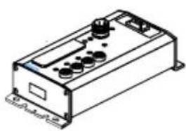
Black-and-white photo of industrial electrical modules with cylindrical components and mounting holes (no visible text or symbols)FESTO
Description Electronics
CPV valve terminal with direct connection
Field bus protocol: INTERBUS-Loop Direct connection type CPV...-GE-IL-...
natural_image
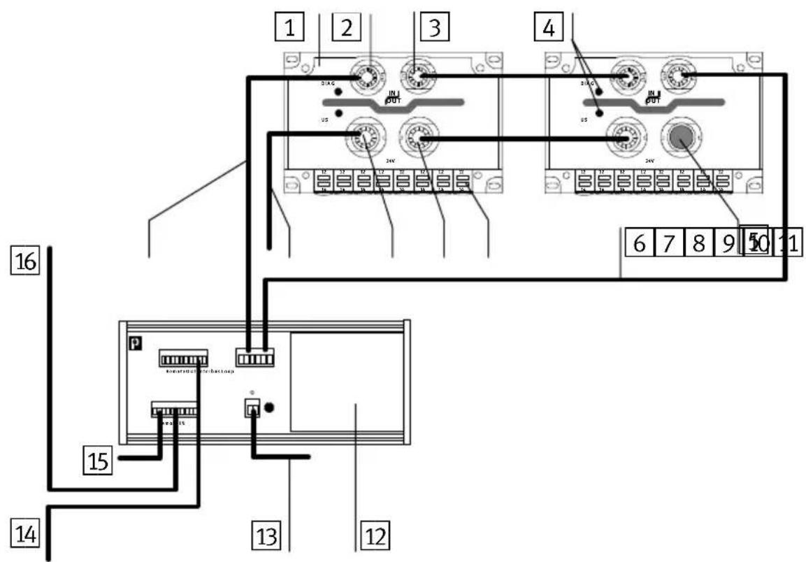
Isometric line drawing of a rectangular electronic device with control knobs and ports (no text or symbols)Description 175 509 en 0112c
Contents and general instructions
Author ...... H. Hohner, E. Klotz, M. Simons
Editors ...... H.-J. Drung, M.Holder
Original de.
Type setting DUCOM.....
Edition en 0112c.
.......Title MANUAL-EN
Designation P.BE--CP-IL-EN
Order no. 175 509
© (Festo SE & Co. KG, D-73726 Esslingen, Federal Republic of Germany 2000)
Internet: http://www.festo.com
E-Mail: service_international@festo.com
The copying, distribution and utilization of this document as well as the communication of its contents to others without expressed authorization is prohibited. Offenders will be held liable for the payment of damages. All rights reserved, in particular the right to carry out patent, utility model or ornamental design registration.
Contents and general instructions
Contents
Designated use V.
Target group VI.
Service VI
Notes on the use of this manual . . . . . . . . . . . . . . . . . . . . . . . . . . . . . . . . . . . . . . . . . . . . VI
Important user instructions VII
1. Installation 1-1
1.1 General notes on installation 1-3
1.2 Description of the product 1-4
1.3 Structure of the INTERBUS-Loop 1-5
1.4 Pin assignment 1-6
1.5 Connecting the CPV valve terminal 1-7
1.5.1 Structure of the Quickon screw connector 1-7
1.5.2 Preparing the connecting cable 1-8
1.5.3 Connecting the cables 1-10
1.5.4 Fitting the blind plug 1-11
1.5.5 Selecting the power unit 1-13
1.5.6 Notes on connecting the power supply 1-14
1.5.7 Earthing 1-18
2. Commissioning 2-1
2.1 Commissioning on an INTERBUS master 2-3
2.1.1 General 2-4
2.2 Switching on the power supply 2-5
2.3 Addressing variants 2-6
2.4 Number of outputs and ID code 2-6
2.5 Bus configuration 2-7
2.5.1 Bus configuration with CMD software 2-7
2.5.2 Bus configuration without CMD software 2-14
2.6 Basic rules for addressing CPV valve terminals 2-18.....
2.6.1 Addressing the CPV valve terminal 2-19
2.6.2 Process data entry via the CMD software 2-23
2.7 Preprocessing 2-26
2.8 Periphery fault (PF) 2-26
- Diagnosis 3-1
3.1 Summary of diagnostic possibilities 3-3
3.2 Diagnosis via LEDs 3-4
3.2.1 Normal operating status 3-5
3.2.2 Error display (US) 3-5
3.2.3 Error display (DIAG) 3-6
3.2.4 Displays of the valve coils 3-7
3.3 Diagnosis via INTERBUS 3-8
3.4 Error treatment 3-9
3.4.1 Reaction to faults in the control system 3-9
A. Technical appendix ...... A-1
A.1 Technical specifications.... A-3
A.2 Accessories A-7
A.3 Dimensions A-8
B. Index B-1
Designateduse
The CPV valve terminal type CPV-... with direct connection to the INTERBUS-Loop type CPV..-GE-IL-... described in this manual is intended exclusively for use as a slave on the INTERBUS-Loop and compatible field buses. The CPV valve terminal may only be used as follows:
– in accordance with designated use
– in its original condition
– without any modifications
– in perfect technical condition
The values specified for pressures, temperatures, electrical data, torques, etc. must be observed.
Please comply with technical regulations as well as national and local regulations in your country.
When implementing an emergency stop circuit, observe also the measures listed in Chapter 1.5.6.


Warning
If to be used as an explosion-protected operating device, make sure that:
• electrical contacts are not disconnected under tension
- the completely fitted product with all plugs, adapters and protective caps complies at least with protection class IP 64.
Targetgroup
This manual is intended for technicians who are trained in control and automation technology, and who have experience in installing, commissioning, programmierung and diagnosing slaves on the INTERBUS.
Service
Please consult your local Festo repair service if you have any technical problems.
Notesontheuseofthismanual

Pleasenote
This manual describes the functioning of the software version 1.x and the hardware version 04/98 of the CPV valve terminal with direct connection to the INTERBUS-Loop.
This manual contains specific information on installing, commissioning, configuring and diagnosing CPV valve terminals with direct connection for the INTERBUS-Loop.
Information on fitting and on the pneumatic components of the CPV valve terminal can be found in the pneumatics manual “P.BE-CPV-...”.
Importantuserinstructions
Danger categories
This manual contains instructions on the possible dangers which may occur if the product is not used correctly. These instructions are marked (Warning, Caution, etc), printed on a shaded background and marked additionally with a pictogram. A distinction is made between the following danger warnings:

Warning
... This means that failure to observe this instruction may result in serious personal injury or damage to property.

Caution
... This means that failure to observe this instruction may result in personal injury or damage to property.

Pleasenote
... This means that failure to observe this instruction may result in damage to property.

The following pictogram marks passages in the text which describe activities with electrostatically sensitive components.
Electrostatically sensitive components may be damaged if they are not handled correctly.

Marking special information
The following pictograms mark passages in the text containing special information.
Pictograms
Information:
Recommendations, tips and references to other information sources.

Accessories:
Information on necessary or sensible accessories for the Festo product.

Environment:
Information on environment-friendly use of Festo products.
Textmarkings
- The bullet indicates activites which may be carried out in any order.
- Figures denote activities which must be carried out in the numerical order specified.
– Hyphens indicate general activities.
The following product specific terms and abbreviations are used in this manual:
| Term/abbreviation | Meaning |
| O Digital output | |
| OB Output byte | |
| CP Compact Performance | |
| CPV Direct | CPV valve terminal with fieldbus direct connection |
| CP System | Complete system consisting of CPV Direct and CP modules |
| CP Anschluss | Socket or plug on the CP modules with which they are connected to the node by means of the CP cables |
| CP Modules | Common term for the various modules which can be incorporated in a CP system |
| CP-Cable | Special cable for connecting the various CP modules |
| I Digital input | |
| I/O Module | Common term for the CP modules which provide digital inputs and outputs (CP input and CP output modules) |
| IO/s | Digitale In and Output |
| PLC/IPC | Programmable logic controller/industrial PC |
Contents and general instructions
Installation
Chapter1
- Installation
Contents
1. Installation1-1.....
1.1 General notes on installation 1-3
1.2 Description of the product 1-4
1.3 Structure of the INTERBUS-Loop 1-5
1.4 Pin assignment 1-6
1.5 Connecting the CPV valve terminal 1-7
1.5.1 Structure of the Quickon screw connector 1-7
1.5.2 Preparing the connecting cable 1-8
1.5.3 Connecting the cables 1-10
1.5.4 Fitting the blind plug 1-11
1.5.5 Selecting the power unit 1-13
1.5.6 Notes on connecting the power supply 1-14
1.5.7 Earthing 1-18
1. Installation
1.1 General notes on installation

Warning
Before undertaking installation and maintenance work, switch off the following:
•the compressed air supply
- the operating voltage supply to the bus terminal
- the load voltage supply to the CPV valves
You can thereby avoid:
– uncontrolled movements of loose tubing
- undesired movements of the connected actuators
– undefined switching states of the electronic components
1. Installation
1.2 Description of the product
CPV valve terminal type CPVxx-GE-IL is a valve terminal for connecting to the INTERBUS-Loop. It enables control of maximum 16 valve coils (single or double solenoid valves) per valve terminal. It is distinguished by the following features:
– simple, at fast connection to the bus in Quickon technology
– simple, fast connection of the load voltage in Quickon technology
- Status and diagnostic LEDs
– electrical isolation between the CPV valves and the bus
With the INTERBUS-Loop you can network sensors and actuators which are decentrally distributed on machines or systems. The Loop is coupled to the INTERBUS by means of a bus terminal. Up to 32 bus slaves can be connected via two two-core unscreened cables. The cables are used for data transport and for the power supply to the connected bus slaves.

Pleasenote
Operation of the INTERBUS-Loop requires the appropriate firmware versions in the various INTERBUS master modules. Consult the supplier of the master module for the correct firmware version.
1. Installation
1.3 StructureoftheINTERBUS-Loop
The diagram below shows the basic structure of an INTERBUS-Loop ring.
text_image
1 2 3 4 5 6 7 8 9 10 11 12 13 14 15 16 2A G IN OUT 2N 2V 2A G IN OUT 2N 2V 2A G IN OUT 2N 2V 2A G IN OUT 2N 2V 2A G IN OUT 2N 2V 2A G IN OUT 2N 2V 2A G IN OUT1 CPV ...-IL valve terminal
2 BUS IN connection
3 BUS OUT connection
4 Diagnosis/status LEDs
5 Blind plug for valve supply
6 INTERBUS-Loop return cable
7 Valve coil status LED
8 Valve supply connection OUT
9 Valve supply connection IN
10 Valve supply 24 V DC
11 ININTERBUS-Loop incoming cable
12 Bus terminal for INTERBUS-Loop
13 24 V DC supply for INTERBUS-Loop
14Continuing remote bus
15 24 V DC supply for bus terminal
16 Incoming remote bus
Fig. 1/1: CPV valve terminal in INTERBUS-Loop
- Installation
1.4 Pinassignment
The diagram below shows the bus and valve supply connections and their assignment.

text_image
1 2 3 4 DIAG IN OUT US 3 2 1 24V 5 7 5 61 BUS IN +
2 BUS IN -
3 BUS OUT +
4 BUS OUT -
5 24 V DC valve supply
6 0 V valve supply
7 Earth connection for valve supply
Fig. 1/2: Pin assignment of CPV..-IL valve terminal
- Installation
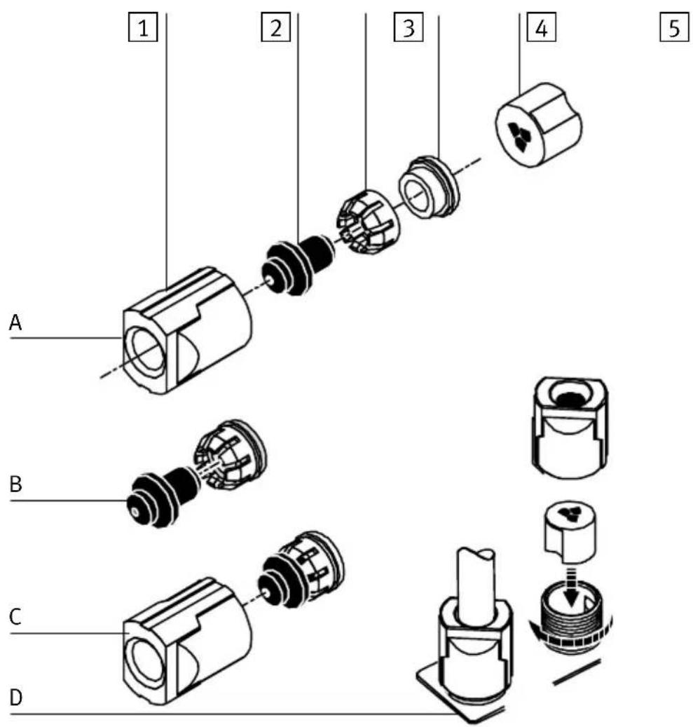
1.5ConnectingtheCPVvalveterminal
1.5.1 Structure of the Quickon screw connector
The diagram below shows the structure of the Quickonscrew connector.
text_image
1 2 3 4 15 mm 6 51 Union nut
2 Crown
3 Sealing rubber
4 Cable cores
5 Splicing ring (2-pin for bus, 3-pin for valve supply)
6 Insulation removed (15 mm)
Fig. 1/3: Structure of Quickon screw connectors
1. Installation
1.5.2 Preparing the connecting cable
Prepare and connect the cable as follows:
- Push the union nut, the crown and the sealing rubber onto the cable. Remove approximately 15 mm of the insulation from the cable (points A and B).

Pleasenote
You must observe the cable specifications in the appendix of this manual and in your controller manual.
-
Push the sealing rubber up to the edge of the insulation and then place the crown on the sealing rubber. This provides strain releif for the cable (point C).
-
Insert the ends of the cable cores into the openings of the splicing ring (point D).

Pleasenote
The splicing ring for the bus and that for the supply to the valves differ as follows:
– the splicing ring for the bus is 2-pin
– the splicing ring for the valve supply is 3-pin
- Cut off the projecting cable core ends. Make sure that the ends of the cores are flush with the splicing ring. They must not project and must not be too short.
1. Installation

text_image
IN OUT 2 1 2 1 24V 3 2 1 A B C DFig. 1/4: Mounting sequence for Quickon screw connectors
1. Installation
1.5.3 Connecting the cables
- Insert the prepared cable into the appropriate connection on the CPV terminal (A).
- Turn the connection until the codings fit exactly into the appropriate guides. The codings on the splicing rings prevent connection being made with the incorrect polarity (BUS IN - 2 round codings, BUS OUT-- 2 square codings, valve supply 24V - 3 round codings).
- Close the screw connector by tightening the union nut (B). The ends of the cable cores are then pressed into the piercing devices, the core insulation is cut open and electrical contact is made.
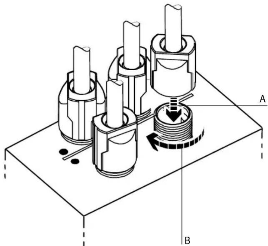
natural_image
Technical diagram of a mechanical assembly with three cylindrical components and a rotating shaft, labeled A and B (no text or symbols beyond labels)Fig. 1/5: Fitting the connecting cables
1. Installation

Pleasenote
In the following cases, carry out additional measures with regard to cable laying and installation:
- when forces occur on the bus cable (tension or pressure)
– with vibration
– when a freely hanging (non-supported) part of the bus cable is longer than 20 cm.
If a valve terminal is fitted into a moving machine, the bus cable must be fitted with strain relief on the moving part of the machine. Observe the appropriate regulations in standard EN 60204 part 1.
1.5.4 Fitting the blind plug

Pleasenote
If you do not use the connection for the continuing valve supply, cover it with a blind plug (see Fig. 1.6). The blind plug is included in delivery the Quickon set, see Appendix A, accessories.
Proceed as follows:
- Place the crown on the sealing rubber and both together on the blind plug (A, B).
- Insert everything together into the union nut.
- Place the splicing ring into the non-required connection of the continuing valve supply (C).
- Place the screw connector upright with the blind plug fitted and tighten the union nut (D).
1. Installation
1 Union nut
2 Blind plug
3 Crown
4 Sealing rubber
5 Splicing ring
text_image
1 2 3 4 5 A B C DFig. 1/6: Fitting the blind plug
1. Installation
1.5.5 Selecting the power unit

Warning
Use only power units which guarantee reliable isolation of the power supply as per IEC 742/EN 60742/VDE 0551 with at least 4 kV isolation resistance (protected extra low voltage, PELV). Switch power packs are permitted if they guarantee reliable isolation in accordance with EN 60950/VDE 0805.
Remark:
By using PELV power units, protection against electric shock (protection against direct and indirect contact) in accordance with EN 60204-1/IEC 204 is guaranteed on Festo valve terminals. Safety transformers with the adjacent designation must be used for supplying PELV networks. The valve terminals must be earthed in order to ensure their function (e.g. EMC).
The current requirement of a CPV valve terminal depends on the number of CPV valve coils and the type of CPV valve terminal.
Recommendation:
- Always use closed-loop power units.
- When selecting the power unit, check that it provides sufficient output. Calculate here the total current consumption.
1. Installation
Total current consumption
The following table shows you how to calculate the total current consumption for an INTERBUS-Loop ring. The values specified have been rounded up.
| BuscurrentconsumptionCPV..-IL-... | Sums | |
| CPV valve terminal 50 mA | ||
| Number of valve terminals | ____ | = ____ mA |
| Currentconsumptionofvalvesupply | ||
| Current consumption of all simultaneously energized valve coils1) | __ x __ mA = ____ | mA |
| 1) Current consumption depends on valve type (see technical specifications for the valves) | ||
1.5.6 Notes on connecting the power supply

Warning
If the valve terminal is supplied with load voltage via the output of a "safety I/O module," start-up test pulses of the "safety I/O module" can lead to unexpected reactions of the valve terminal.
- Make sure that start-up test pulses are reliably suppressed or switched off.

Caution
Fuse the load voltage of the CPV valve coils externally with max. 2 A. The supply to the electronic components (via the INTERBUS-Loop) must be fused externally.
With the external fuse you can avoid functional damage to the CPV valve terminal if there is a short circuit.
- Installation

text_image
DIAG IN OUT US 24V 1 1 1 1 1 1 1 1 1 1 1 1 1 1 1 1 1 1 1 1 1 1 1 1 1 1 1 1 1 1 1 1 1 1 1 1 1 1 1 1 1 1 1 1 1 1 1 1 1 1 2 31 24 V DC valve supply
2 0 V valve supply
3 Earth connection for valve supply
Fig. 1/7: Power supply connection of CPV valve terminal
The current consumption depends on the type of valve coil. The values can be found in the “Pneumatics manual, P.BE-CPV-...”

Hinweis
Check the EMERGENCY STOP circuit to see which measures are required in order to place your machine/system in a safe state in the event of an emergency stop:
– switching off the load voltage of the valves and output modules in the secondary circuit of the power unit
– switching off the compressed air supply for the valve terminal.
Due to energy stored in the input circuitry of valve terminals, there may be a delay when the load voltage is switched off before the valves are switched off.
Take this into account, e.g. as follows:
- Register the load voltage switch-off by means of an input signal in the controller.
- Block the actuation signal of the valves by locking the output signal with the input signal "load voltage."
Recommendation:
- Check the 24 V load voltage whilst the system is in operation. Make sure that the load voltage lies within the permitted tolerance, even during full operation.
-
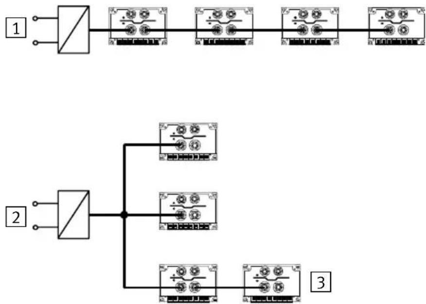
Check which connecting variant of the load voltage is suitable for your application (see following diagram).
-
Installation
The load voltage supply for the CPV valve terminals is usually looped through (1). If the voltage on the supply cable drops below the minimum value (load voltage <20.6 V), the supply can also be made star-shaped (2). Several CPV valve terminals can still be switched in series within the star-shaped arrangement (3).
flowchart
graph TD
    A["Switch 1"] --> B["Component 1"]
    B --> C["Switch 2"]
    C --> D["Component 2"]
    D --> E["Switch 3"]
    E --> F["Component 3"]
Fig. 1/8: Connecting variants for the load voltage of the CPV valve terminals
1. Installation
1.5.7 Earthing
The CPV valve terminal has 2 functional earth connections:
• on the load voltage connection of the CPV valve terminal
• on the left-hand end plate

Pleasenote
- Always connect the earth potential to the load voltage connection.
- Connect the earth connection of the left-hand end plate with low impedance (short cable with large diameter).
- By means of low-impedance connections, make sure that the housing of the CPV valve terminal and the earth cable on the load voltage connection have the same potential and that there are no equalizing currents.
In this way you can avoid interference due to electromagnetic influences.
Commissioning
Chapter2
2. Commissioning
Contents
2. Commissioning2-1.
2.1 Commissioning on an INTERBUS master 2-3
2.1.1 General 2-4.....
2.2 Switching on the power supply 2-5
2.3 Addressing variants 2-6
2.4 Number of outputs and ID code 2-6
2.5 Bus configuration 2-7
2.5.1 Bus configuration with CMD software 2-7
2.5.2 Bus configuration without CMD software 2-14
2.6 Basic rules for addressing CPV valve terminals 2-18
2.6.1 Addressing the CPV valve terminal 2-19
2.6.2 Process data entry via the CMD software 2-23
2.7 Preprocessing 2-26
2.8 Periphery fault (PF) 2-26
2. Commissioning
2.1 CommissioningonanINTERBUSmaster
This chapter describes the configuration and addressing of a CPV valve terminal with INTERBUS-Loop connection to an INTERBUS master or compatible master.
A general and comprehensive description can be found in the appropriate manual for the CMD software. It is assumed in the following that the user is familiar with the contents of the CMD manual.

Pleasenote
The software packages are subject to modifications which are not taken into account in this manual.
The examples used here for the screen displays have been taken from CMD software version 4.
Further and current information can be found in the manuals for the CMD software and for your control system.
2. Commissioning
2.1.1 General
Before commissioning or programming, you should compile a configuration list of all connected field bus slaves. On the basis of this list you can:
- carry out a comparison between NOMINAL and ACTUAL configurations in order to recognize connection faults.
- access these specifications again during the addressing and syntax check, in order to avoid addressing faults.
Please note here the information in the following sections.
2. Commissioning
2.2 Switching on the powersupply

Pleasenote
Read also the switching-on instructions in the PLC manual for your controller.
When the controller is switched on, it automatically carries out a comparison between the NOMINAL and the ACTUAL configurations. For this configuration run it is important that:
- The configuration specifications are complete and correct
- The field bus slaves are supplied with power, in order that they can be recognized when the ACTUAL config ascertained.
Switch on the power supply for the controller and all the field busslavesatthesametime, e.g. by means of acent switch. Or switch on the power supply in the following sequence:
-
The power supply for all the field bus slaves or all active bus segments.
-
Then the power supply for the controller.
2. Commissioning
2.3 Addressingvariants
The CPV valve terminal with INTERBUS-Loop supports the following addressing variants, depending on the module and PLC used:
- configuration via the CMD software
- logical addressing
- physical addressing
The individual addressing variants are explained in detail below.

Pleasenote
The I/O addresses for the bus slaves are set on the INTER-BUS controller board by means of switches or by software. No address settings are necessary on the CPV valve terminal.
2.4NumberofoutputsandIDcode

Pleasenote
The CPV valve terminal occupies 8 or 16 outputs, depending on the equipment fitted, i.e. the number of valve plates and the type of valve plates.
2. Commissioning
- Select the appropriate values forth el D code and t cess data channel.
| Type | Ident-CodeProcessdata channel(outputs) | |
| CPV10-GE-IL-8 177 | _D/B1_H | 16 Bit |
| CPV14-GE-IL-4 177 | _D/B1_H | 8 Bit |
| CPV14-GE-IL-8 177 | _D/B1_H | 16 Bit |
2.5Busconfiguration
2.5.1 Bus configuration with CMD software
This chapter describes as an example the main steps which you will require within the CMD software, in order to insert a CPV valve terminal into your project. A general and comprehensive description can be found in the relevant manual for the CMD software. In the following it is assumed that the user is familiar with the contents of the CMD manual.

Pleasenote
The CPV valve terminal with an INTERBUS-Loop module can only be added to an appropriate bustermal (IBS SL 24 BK-T).
2. Commissioning
Inserting with the Ident code
- Open the dialogue window of the bus terminal for the INTERBUS-Loop. Select the option "Insert with Ident code...."

text_image
IBS CMD G4 c:\IBSCMDGB\PROJECT\NONAME.BG4 File Edit View Configuration Monitor Diagnostics Options ? F3: State F4: Save F5: Open F7: Represent. F8: Search Project PLC/PC Program Controller Board Parameterization Memory Preprocessing Configuration Frame Paste Ctrl+V Insert with Ident Code... Insert with Device Description... Ins. Link with Description Description... F9 Process Data... Strg+D Parameterization Settings ... Control Type... IB Function Blocks Device Registration Address Monitor Ctrl+M... Display IBS DSC Diagnostics Insert new device with ident code and process data lengthFig. 2/1: Inserting bus slaves with the Ident code
The following dialogue window will then appear:
2. Commissioning
text_image
Insert Device ID Code: 177 dec. Process Data Channel: 16 Bit Device Type: Local bus device OK Cancel HelpFig. 2/2: Dialogue window "Insert device"
Enter the following in the dialogue window:
- Ident code:
Ident code 177 must be entered for the CPV valve terminal with INTERBUS-Loop.
- Process data channel:
Enter 8 or 16 bits under "Process data channel," depending on the type of your valve terminal.
| Type | Ident-CodeProcessdata channel(outputs) | |
| CPV10-GE-IL-8 177 | _D/B1_H | 16 Bit |
| CPV14-GE-IL-4 177 | _D/B1_H | 8 Bit |
| CPV14-GE-IL-8 177 | _D/B1_H | 16 Bit |
- Slave type:
The default entry Local bus device can be entered.
• Save these entries with OK.
2. Commissioning
Insert slave description
In the following input mask you can describe the slave and enter specific information on the CPV valve terminal, e.g. station name and a picture of the slave.

text_image
Insert Device Description Device Description Interface Type ... Device Number: 2.2 Icon ... Group Number: Parameter Channel ... Station Name: Service Information: Use Station Name Device Name: Manufacturer Name: FESTO Device Type: CPV10-GE-IBL Ident Code: 177 dec. Profile Number: 0 hex. Process Data 16 Bit Parameter Channel: 0 Bit Gray out device OK Cancel HelpFig. 2/3: Dialogue window "Insert Device Description"
2. Commissioning
Possible entries:
- Interface type:
The default entry “Interface type universal” can be entered here.
•Picture:
Open the dialogue window “Picture...,” if you wish to use specific icons for the Festo valve terminal.

Pleasenote
The specific iconslcons of the Festo valve terminals of the Festo valve terminals can be found on the accompanying CD-ROM.
- Read the text “Readme.txt” on the CD-ROM, for a quick survey of the contents of the CD-ROM.
- Copy the file "Festo.ICL" into the CMD directory PICTURE.
2. Commissioning
The following dialogue window will then appear:
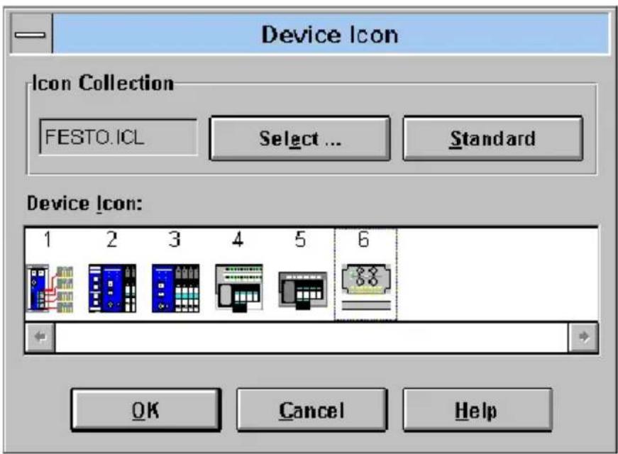
text_image
Device Icon Icon Collection FESTO.ICL Select ... Standard Device Icon: 1 2 3 4 5 6 OK Cancel HelpFig. 2/4: Dialogue window "Device Icon" for selecting an icon
Proceed as follows:
- Change from one installed icon file to the other with the box "Select ... "
- Select the file Festo.ICL.
- Mark icon 6 (it corresponds to your CPV valve terminal for the INTERBUS-Loop).
• Enter this icon with OK.
2. Commissioning
The icons are numbered. The following table show: tionship between the number of the icon and the valve terminal type.
| Iconno. | Valveterminaltype |
| 1 Type 10 | |
| 2 | Types 03-05 with inputs and outputs |
| 3 | Types 03-05 only with valves and/or outputs |
| 4 | Type 02 with inputs and outputs |
| 5 Type 02 | only with valves |
| 6 Type 10 | CPVwithINTERBUS-Loop |
When all the entries have been made, the valve terminal will be integrated into your bus structure.
2. Commissioning
2.5.2 Bus configuration without CMD software
Logical addressing

Pleasenote
Configure a CPV valve terminal as follows:
•ID CODE: 177D (B1 H)
-Processdatachannel:8or16bits
•Number of outputs: 8 or 16
•Number of inputs: 0
One or several configuration list(s) is/are created in the PLC or the INTERBUS-Loop for the logical addressing. These configuration lists contain at least the following entries:
– the ID codes of all the slaves
– the logical addresses of all the slaves
– the number of inputs
- the number of outputs
2. Commissioning
These specifications must be known or ascertained for each bus slave. Proceed as follows in the case of the CPV valve terminals:
- Assign ID code 177 _D to each CPV valve terminal.
- Assign a logical number to each CPV valve terminal.
- Assign a logical OUT address and, depending on the type of your valve terminal, 8 or 16 bit outputs to each CPV valve terminal.
| Type | Ident-CodeProcessdata channel(outputs) | |
| CPV10-GE-IL-8 177 | _D/B1_H | 16 Bit |
| CPV14-GE-IL-4 177 | _D/B1_H | 8 Bit |
| CPV14-GE-IL-8 177 | _D/B1_H | 16 Bit |
Physical addressing

Pleasenote
Providing your INTERBUS-Loop permits this, use the logical addressing or the bus configuration via the CMD software.
In this way you will avoid shifting output addresses when extensions are made later.
The first bus slave is addressed with the basis address (BA) of the INTERBUS-Loop. You can obtain the address of the next bus slave by adding the appropriate number of bits of the process data channel of all the previous slaves to the basis address. This procedure must be carried out separately for the inputs and outputs.

Pleasenote
Depending on the type of valve terminal, the CPV valve terminal occupies 8 or 16 outputs.
| Type | Ident-CodeProcessdata channel(outputs) | |
| CPV10-GE-IL-8 177 | _D/B1_H | 16 Bit |
| CPV14-GE-IL-4 177 | _D/B1_H | 8 Bit |
| CPV14-GE-IL-8 177 | _D/B1_H | 16 Bit |
2. Commissioning
Example of physical addressing:
- 1st. slave: 32 inputs/32 outputs,
- 2nd. slave: bus terminal IBS SL 24....,
- 3rd.- 5th. slave: CPV10 valve terminals with 16 outputs
| 1st.slave xxx2 | 2nd.slave IBSSL24.. | 3rd.slave CPV...IL | 4th.slave CPV...IL | 5th.slave CPV...IL | |
| Processdata channelbits | 32 0 16 | 16 16 | |||
| Physical address | BA | BA+32 | BA+32+0 | BA+32+0+16 | BA+32+0+16+16 |
| BA = Basic address | |||||
2. Commissioning
2.6 Basic rules for addressing CPV valveterminals
Depending on the type of valve terminal, the CPV valve terminal occupies 8 or 16 outputs. This enables the CPV valve terminal to be extended at a later stage without the need to shift the addresses.
The following diagram shows the addressing sequence of the individual CPV valve plates.
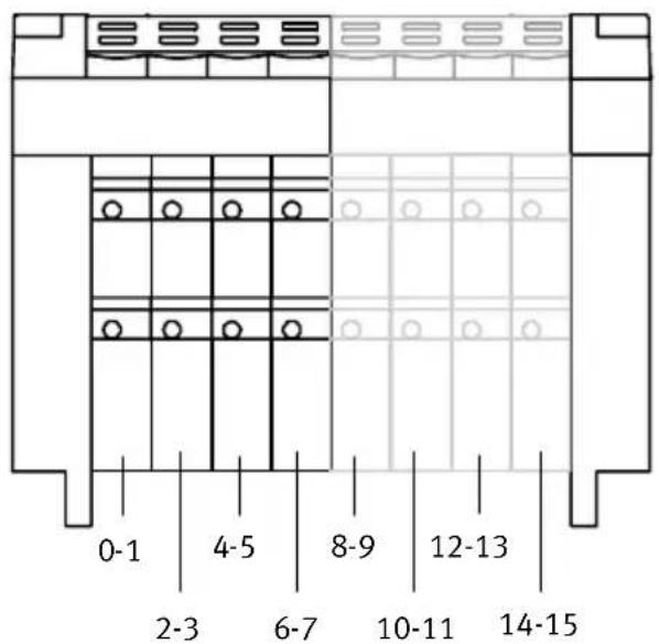
text_image
0-1 2-3 4-5 6-7 8-9 10-11 12-13 14-15Fig.2/5: AddressassignmentofaCPVvalveterminal

Pleasenote
The following applies: Lower value address → pilot solenoid 14 Higher value address → pilot solenoid 12
2. Commissioning
2.6.1 Addressing the CPV valve terminal
Further information on addressing can be found in the manuals for your controller and the INTERBUS-Loop.
The address assignment (process data assignment) of the outputs/coins of a CPV valve terminal on the INTERBUS-Loop or compatible system depends firstly on the INTERBUS module and on the control system used.

Caution
There are different address assignments on the INTERBUS. This is because of the assignment of the process data within the INTERBUS module and not within the CPV valve terminal.
- Note the assignment of the high and low bytes when assigning the addresses, as the position of these bytes may be swapped when certain control systems are used.
In this way you will avoid errors in addressing the valve terminal.
2. Commissioning
The following examples give basic information on the different address assignmentsAddress assignment and the position of the low byte (n) and the high byte (n+1). A distinction is made here between the:
•Siemens mode and the
- Standard mode
Example:
- In the Siemensmodethelowervalueoutputbyte is mapped on valve coils 0-7 of the valve terminal, byte n+1 on the next coils (8-15).
- In the Standardmodethelowervalueoutputbyte(n) is mapped on valve coils 8-15 of the valve terminal, byte n+1 on coils 0-7.
2. Commissioning
Example of Siemens mode
The following diagram shows the assignment of the CPV valve coils to the addresses in Siemens mode.

text_image
DIAG IN OUT US 24V 12 12 12 12 12 12 12 12 14 14 14 14 14 14 14 1 3 5 7 9 11 13 15 0 2 4 6 8 10 12 14 1 3 5 7 1 3 5 7 0 Q Q Q Q Q Q Q Q Q Q Q Q Q Q Q Q Q Q Q Q Q 1 3 5 7 1 3 5 7 0 Q Q Q Q Q Q Q Q Q Q Q Q Q Q Q Q Q Q Q Q Q Q Q Q Q Q Q Q Q Q Q Q Q Q Q Q Q Q Q Q Q Q Q Q Q Q Q Q Q Q Q Q Q Q Q Q Q Q Q Q Q Q Q Q Q Q Q Q Q Q Q Q Q Q Q Q Q Q Q Q Q Q Q Q Q Q Q Q Q Q Q Q Q Q Q Q Q Q Q Q Q Q Q Q Q Q Q Q Q Q Q Q Q Q Q Q Q Qatar Q Qatar Q Qatar Q Qatar Q Qatar Q Qatar Q Qatar Q Qatar Q Qatar Q Qatar Q Qatar Q Qatar Q Qatar Q Qatar Q Qatar Q Qatar Q Qatar Q Qatar Q Qatar Q Qatar Q Qatar Q Qatar Q Qatar Q Qatar Q Qatar Q Qatar Q Qatar Q Qatar Q Qatar Q Qatar Q Qatar Q Qatar Q Qatar Q Qatar QQR QQR QQR QQR QQR QQR QQR QQR QQR QQR QQR QQR QQR QQR QQR QQR QQR QQR QQR QQR QQR QQR QQR QQR QQR QQR QQR QQR QQR QQR QQR QQR QQR QQRFig. 2/6: Assignment of the valve coils (Siemens mode)
2. Commissioning
Example of Standard mode
The following diagram shows the assignment of the CPV valve coils to the addresses in standard mode.

text_image
DIAG IN OUT US 24V 12 12 12 12 12 12 12 12 12 14 14 14 14 14 14 14 14 9 11 13 15 1 3 5 7 8 10 12 14 0 2 4 6 1 3 5 7 0 0 0 0 0 0 0 0 0 2 4 6 0 3 5 7 0 0 0 0 0 0 0 0 0 0 0 0 0 0 0 0Fig. 2/7: Assignment of the valve coils (Standard mode)
2. Commissioning
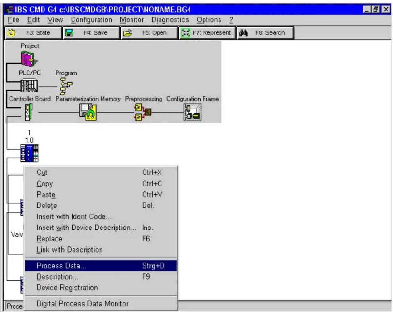
2.6.2 Process data entry via the CMD software
As from version 4.x, the CMD software offers the possibility of assigning any output to the PLC/IPC within the configured address range of the valve coil. In order to do this, proceed as follows:
- Add your CPV valve terminal to your bus structure (necessary steps see section 2.5.1 “Bus configuration with CMD software”).
- Use theright-hand mouse key to open the dialogues dow of the inserted CPV valve terminal.
- Select the option "Process data."
2. Commissioning
text_image
IBS CMD G4 c:\IBSCMDGB\PROJECT\NONAME.BG4 File Edit View Configuration Monitor Diagnostics Options ? F3: State F4: Save F5: Open F7: Represent. F8: Search Project PLC/PC Program Controller Board Parameterization Memory Preprocessing Configuration Frame 1 1.0 Cut Ctrl+X Copy Ctrl+C Paste Ctrl+V Delete Del. Insert with Ident Code... Insert with Device Description... Ins. Replace F6 Link with Description Valv Process Data... Strg+D Description... F9 Device Registration Proce: Digital Process Data MonitorFig. 2/8: Option for entering the process data
2. Commissioning
In the following menu you can determine the I/O addresses (example: Siemens mode, byte-by-byte assignment for an S5).
| Process Data From Device: 2.1. | |||||||||
| Location | Process Data Name | I/O | Length | Byte | Bit | MA | Assignments | ||
| 1 | <||||||||,...... | Coil 0 - 7 | O | 8 | 0 | 0 | ☐ | P32 | |
| 2 | <......|||||| | Coil 8 - 15 | O | 8 | 1 | 0 | ☐ | P33 | |
| 3 | <|||||||||||||| | 16-Bit_Output_1 | O | 16 | 0 | 0 | ☐ | ||
Fig. 2/9: Entering process data – example of Siemens mode

Pleasenote
You need only swap the assignment of the two bytes in order to correct the byte swap.
An individual I/O assignment at bit level is only necessary in certain cases.
The following dialogue window shows the entries required for swapping/correcting the assignment of the high byte and low byte (example: byte swap for Standard mode).

text_image
Process Data From Device: 2.1. Location Process Data Name I/O Length Byte Bit MA Assignments 1 Coil 0 - 7 0 8 0 0 □ P33 2 Coil 8 - 15 0 8 1 0 □ P32 3 16-Bit_Output_1 0 16 0 0 □Fig. 2/10: Byte swap correction – example of Standard mode
- Commissioning
2.7 Preprocessing
Under preprocessing we understand the logical linking of process data within the INTERBUS module (formerly known as event programming or receive bit manipulation).

Pleasenote
All the valves on a CPV valve terminal can be preprocessed.
2.8 Periphery fault (PF)
The Festo CPV valve terminal on the INTERBUS-Loop does not generate a periphery fault.
Diagnosis
Chapter3
- Diagnosis
Contents
3.Diagnosis3-1.
3.1 Summary of diagnostic possibilities 3-3.
3.2 Diagnosis via LEDs 3-4.
3.2.1 Normal operating status 3-5
3.2.2 Error display (US) 3-5
3.2.3 Error display (DIAG) 3-6
3.2.4 Displays of the valve coils 3-7
3.3 Diagnosis via INTERBUS 3-8
3.4 Error treatment 3-9
3.4.1 Reaction to faults in the control system 3-9
3. Diagnosis
3.1 Summary of diagnostic possibilities
The CPV valve terminal with connection to the INTERBUS-Loop offers the following possibilities of diagnosis and fault treatment:
– Diagnosis via the built-in LEDs (see Chapter 3.2).
- bus status (DIAG, green)
- status of the load voltage supply (US, green)
– valve status display (valve coils 12 and 14, yellow)
– Diagnosis via the INTERBUS diagnostic status register (see Chapter 3.3).
3. Diagnosis
3.2DiagnosisviaLEDs
The LEDs on the CPV valve terminal indicate the operating and/or error status.

text_image
1 2 US IN OUT 24V 12 12 12 12 12 12 12 12 14 14 14 14 14 14 14 31 Bus status/error LED "DIAG"
2 Power supply LED (load voltage supply) "US"
3 Valve status display
Fig. 3/1: Diagnosis LEDs of the CPV valve terminal
3. Diagnosis
3.2.1 Normal operating status
In the normal operating status the DIAG LED and the US LED light up.

| LED | StatusSequence | Operating | Error treatment | |
| DIAG |  |  | Normal None | |
| US |  |  | Normal None |
3.2.2 Error display (US)
This “US” LED shows the following undervoltage in the load voltage supply or the failure of the load voltage supply of a CPV valve terminal.
| LED | StatusSequence | Operatingstatus | Error treatment | |
| US |  |  | - Undervoltage in CPV load voltage < 17,7 V ^1) - Failure of CPV load voltage | •Check voltage supply •Check voltage supply1) |
| 1) 17,7 V as from hardware version May 1998 17,1 V up to hardware version April 1998 | ||||

Pleasenote
A voltage failure or an undervoltage in the load voltage of the CPV valve terminal does not produce a periphery fault (PF) on the INTERBUS-Loop.
3. Diagnosis
3.2.3 Error display (DIAG)
Error displays of the green LED "DIAG":
| LED | Status | Sequence | Operating status | Error treatment |
| DIAG |  | ONOFF | -INTERBUS in a | • Start buse |
 | ONOFF | -Bus interruption | • Eliminate interruption | |
 | ONOFF | -Excess temperature on INTERBUS protocol chip LPC21).Message OBC3H | • Current consumption in ring too high- Reduce current consumption-- Reduce number of slaves | |
 | ONOFF | -Bus undervoltage (VBus<24 V)Message OBC2H (message remains saved until voltage supply is switched on/off) | • Reduce ring length | |
| 1) Only as from hardware status May 98. | ||||

Pleasenote
The voltage supply of the INTERBUS-Loop and the load voltage supply of the valves are monitored separately. Only the bus undervoltage produces an error message on the INTERBUS module.
3. Diagnosis
3.2.4 Displays of the valve coils
There is a yellow LED for every valve solenoid coil. This LED indicates the operating status of the relevant valve solenoid coil.

Pleasenote
On valve plates with Ident code F or M, LED 14 is inactive, as these valve plates only possess pilot solenoid coil 12.
12 Yellow LED row for pilot solenoid 12
14 Yellow LED row for pilot solenoid 14
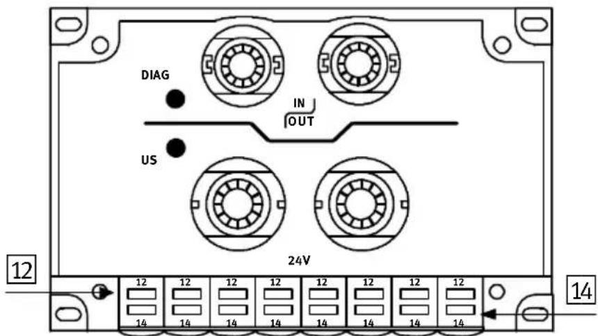
text_image
DIAG IN OUT US 12 14 12 12 12 12 12 12 12 12 12 14 14 14 14 14 14 14 14Fig. 3/2: LEDs of the valve solenoid coils
| LED | Switchpositionof valvesolenoidcoil | Meaning |
| Yellow out | Basic position | Logical 0 (no signal) |
| Yellow alight•switch position | or•basic position | Logical 1 (signal present)Logical 1 but:load voltage supply of valves lies below the permitted tolerance range (< 20.4 V DC) orfault in compressed air supply orpilot exhaust blocked orreturn for servicing |
3. Diagnosis
3.3DiagnosisviaINTERBUS
The CPV valve terminal with connection to the INTERBUS-Loop supports the INTERBUS typical diagnosis via:
• the diagnostic status register and
•the diagnostic parameter register
The following error messages are entered in the diagnostic register:
- interruptions in the INTERBUS-Loop ring
– bus undervoltage (see Chapter 3.2.3)
– excess temperature on the INTERBUS protocol chip (see Chapter 3.2.3)
The representation and further processing of these error messages depends on the INTERBUS master. Please read the procedure for processing and evaluating the error messages described in your master manual.

Pleasenote
An undervoltage in the 24 V load voltage supply for a CPV valve terminal does not trigger an error message on the INTERBUS-Loop.
3. Diagnosis
3.4 Error treatment
3.4.1 Reaction to faults in the control system
The CPV valves are switched off after 25 ms when there is a bus interruption.

Pleasenote
If the outputs are reset after a PLC stop or a field bus interruption, note the following in respect of the pneumatic valves:
– unilaterally-actuated valves move to the basic position
– bilaterally-actuated valves remain in their current position
– mid-position valves move to mid-position (depending on the valve type: pressurized, exhausted or blocked).
- Diagnosis
Technicalappendix
AppendixA
A. Technical appendix
Contents
A. Technical appendix A-1.
A.1 Technical specifications A-3.....
A.2 Accessories A-7....
A.3 Dimensions A-8
A.1 Technical specifications
| General | |
| Temperaturerangeoperationstorage | -5 °C ... +50 °C- 20 °C ... +70 °C |
| Relativehumidity95 % non condensing | |
| ProtectionclassasperEN60529Connector plugged in or fitted with protective cap | IP 65 |
| Protectionagainstelectricshock(protection against direct and indirect contact as per EN 60204-1/IEC 204) | b y m e a n s o f P E L V p o w e r u n i t s (p r o t e c t e d e x low voltage) |
| Protectionagainstexplosion(per EU guideline 94/9/EG, EN 50021 and EN 50281-1-1) Do not disconnect when under ten-sion! | II 3 G/D EEx nA II T5 X - 5 °C ≤Ta ≤+ 50 °CT80°CIP65 (y e a r o f m a n u f a c t u r e s e e X - i d e r cation on the product).Plugs or adapters of the electric connections must comply at least with protection class IP64! |
| Valves | see Pneumatics manual type P.BE-CPV-... |
| Cableconnection:Bus– current loadingLoad voltage– current loading | PG11; 1.5 mm ^2 ≤1.5 APG13.5; 1.5 mm ^2 10 A (max.) |
LoadvoltageofsolenoidvalvesonCPVvalveterminal
| Loadvoltageconnection:– Rated value (protected against incorrect polarity)– Residual ripple– Max. starting current (– Holding current after reduction | 24 V DC (20 V...30 V DC)1.2 VppCPV 10 CPV1433 mA 35 mA12 mA 18 mA |
| Protected against incorrect polarity | by means of serial diode |
| Bridging time during logic voltage failure | 20 ms |
Operatingvoltageofbusinterface/internalelectronics
| INTERBUS-Loopconnection– Voltage range (protected against incorrect polarity)– Residual ripple– Current consumption– Protection against incorrect polarity– Electrical isolation | 24 V DC (DC 10 V...30 V)1.2 Vss48 mAvia bridge-connected rectifieragainst valves |
IdentificationintheINTERBUS
| CPV10-GE-IL-8/CPV14-GE-IL-8: | |
| – Identification code (ID) | 177_D ( B1_H ) |
| – Address range (outputs) | 16 Bit (process data channel) |
| – PCB address range | – |
| – Register length on the bus | 16 Bit |
| – L e n g t h c o d e | 1 ( 1_hex. ) |
| – Extended local bus diagnosis | Yes |
| CPV14-GE-IL-4: | |
| – Identification code (ID) | 177_D ( B1_H ) |
| – Address range (outputs) | 8 Bit (process data channel) |
| – PCB address range | – |
| – Register length on the bus | 8 Bit |
| – L e n g t h c o d e | 1 ( 1_hex. ) |
| – Extended local bus diagnosis | Yes |
| Peripheral diagnostic messages | Bus undervoltage (0BC2)Excess temperature (0BC3)Peripheral error (0BB1) |
Loopspecifications
| CPV10CPV14 | ||
| The CPV valve terminal complies with the Loop specifications up to the following hardware status (see on type plate): | HW 2723385-06 | CPV14/4: HW 2731461-01 CPV14/8: HW 2731267-01 |
| - protocol chip | LPC2 | LPC2 |
| - max. no. of Loop slaves | 32 | 63 |
| - max. distance between 2 Loop slaves | 10 m | 20 m |
| - max. Loop length | 100 m | 200 m |
| - max. ring current | 1.5 A | 1.8 A |
| - earthing | FE load voltage connected directly to valve terminal | FE load voltage connected directly to valve terminal |
| - diagnosis | Slave diagnosis | Slave diagnosis |
Loop2specifications
| CPV10CPV14/4bzw.CPV14/8 | ||
| The CPV valve terminal complies with the Loop 2 specifications up to the following hardware status (see on type plate): | HW 4/2000 | HW 9/1999 |
| - protocol chip | LPC2 | LPC2 |
| - max. no. of Loop slaves | 63 | 63 |
| - max. distance between 2 Loop slaves | 20 m | 20 m |
| - max. Loop length | 200 m | 200 m |
| - max. ring current | 1.8 A | 1.8 A |
| - earthing | FE load voltage connected capacitively to valve terminal | FE load voltage connected capacitively to valve terminal |
| - diagnostics | Slave diagnosis | Slave diagnosis |
Electromagnetic compatibility
| – Interference emission tested as per EN 55011– Resistance to interference tested as per EN 50082-2 | Limit value class A^* |
| *) The CPV valve terminal with direct connection for INTERBUS-Loop type CPV..-GE-IL-... can also be used in residential areas with special permission (living, business and commercial areas, small firms). | |
Technical specifications on the pneumatic components can be found in the “Pneumatics manual, P.BE-CPV-...”.
A.2Accessories
This section gives a summary of the accessories.
Connection to the INTERBUS-Loop

The connections to the bus and to the load voltage are made in the form of Quickon screw connectors. You can order a complete set (each for one CPV valve terminal) from Festo.
Type: Connection set, part no. 175 485
Further accessories

The following accessories from Phoenix Contact are available for connecting the CPV valve terminal to the INTERBUS-Loop:
| Description | TypePartno. | |
| INTERBUS-Loop cable, green, not screened, 2 x 1.5mm ^2 | IBSL SLC CU2/1,5-meter 27 21 | 62 0 |
| INTERBUS-Loop actuator supply cable, black, not screened, 3 x 1.5mm ^2 | IBSL PSC CU3/1,5-meter 27 | 22 13 7 |
| INTERBUS-Loop set(5 blind plugs, 20 conduit screw connectors) | IBSL PG-Set 27 21 99 2 |
Address of Phoenix Contact:
Phoenix Contact GmbH & Co.
Postfach 1341
D-32819 Blomberg,
Germany
Tel: ++49 (0) 5235 3-41200
Fax: ++49 (0)5235 3-00
A. Technical appendix
A.3Dimensions
Dimensions of CPV basic unit with INTERBUS-Loop direct connection

text_image
70 mm(2.756 in.) L3| TypeL1L2L3 | |||
| CPC10-GE-IL-8 | 71 mm | 64 mm | 110 mm |
| CPC14-GE-IL-4 | 89 mm | 64 mm | 96 mm |
| CPC14-GE-IL-8 | 89 mm | 64 mm | 152 mm |
Index
AppendixB
B. Index
Index
A
Accessories A-7.
Address assignment 2-19, 2-20
Addressing CP valve terminals 2-18.
Addressing variants 2-6.....
B
Blind plug 1-11.....
Bus configuration CMD software .... 2-7 logical addressing .... 2-14 physical addressing .... 2-16 without CMD software .... 2-14
Bus interruption 3-9
C
CMD software 2-3
Commissioning 2-4
Connecting cables 1-10
Connecting the operating voltage 1-14
D
Description of the product 1-4.....
Designated use V.
Diagnosis via INTERBUS 3-8
Diagnosis via LEDs 3-4
Diagnostic possibilities 3-3
Dimensions of CPV basic unit ...... A-8
Displays valve coils 3-7
E
EMERGENCY STOP 1-16
Error display (DIAG) 3-6
Error display (US) 3-5
Error treatment 3-9
Example of Siemens mode 2-21, 2-25
Example of Standard mode 2-22
Example of standard mode 2-25
Ex protection V
F
Faults in the control system 3-9
|
Icons of the Festo valve terminals 2-11
ID code 2-6
Important user instructions ..... VII
INTERBUS-Loop 1-4, 1-5
N
Notesontheuseofthismanual VI......
Number of outputs 2-6.....
0
Operating status 3-5.....
P
Periphery fault 2-26
Pin assignment 1-6
Preprocessing 2-26
Process data assignment 2-19
Process data entry 2-23
Programming 2-4
Q
Quickon screw connector 1-7
Quickon screw connectors A-7
S
Service VI
Switching-on instructions 2-5
B. Index
T
Target group VI.
Technical specifications A-3.
Total current consumption 1-14