SFAM-90-10000L-TG112-2SV-M12 - Industrial Automation Festo - Free user manual and instructions
Find the device manual for free SFAM-90-10000L-TG112-2SV-M12 Festo in PDF.

User questions about SFAM-90-10000L-TG112-2SV-M12 Festo
0 question about this device. Answer the ones you know or ask your own.
Ask a new question about this device
Download the instructions for your Industrial Automation in PDF format for free! Find your manual SFAM-90-10000L-TG112-2SV-M12 - Festo and take your electronic device back in hand. On this page are published all the documents necessary for the use of your device. SFAM-90-10000L-TG112-2SV-M12 by Festo.
USER MANUAL SFAM-90-10000L-TG112-2SV-M12 Festo
natural_image
Technical line drawing of a mechanical device with labeled ports and a digital display (no readable text or symbols beyond basic labels)FESTO
en Operating instructions
8078141
2017-09c
[8068109]
Original instructions
SFAM-EN
Identification of hazards and instructions on how to prevent them:

Danger
Immediate dangers which can lead to death or serious injuries

Warning
Hazards that can cause death or serious injuries

Caution
Hazards that can cause minor injuries
Other symbols:

Note
Material damage or loss of function

Recommendations, tips, references to other documentation

Essential or useful accessories

Information on environmentally sound usage
Text designations:
- Activities that may be carried out in any order
- Activities that should be carried out in the order stated
- General lists
→Result of an action/References to more detailed information
English – Flow Sensor SFAM
Table of contents
1 Product description 5.
1.1 Overview 5
1.2 Characteristics 6.
1.3 Factory settings 7
2 Function and application 7.
2.1 Operating statuses 8
2.2 Function range 9
2.2.1 Switching outputs 9
2.2.2 Change in colour 10
2.2.3 Standard conditions 10
2.2.4 Analogue filter 11
2.2.5 Digital filter 11
2.2.6 Security code 11
2.2.7 Min/max values 11
3 Requirements for product use 12
4 Installation 13
4.1 Mechanical/pneumatic installation 13
4.2 Electrical connection 14
5 Commissioning 15
5.1 Symbols on the display 15
5.2 Symbols for representing the menu structure 16
5.3 RUN mode 17
5.4 INFO/SHOW mode 18
5.5 EDIT mode 20
5.5.1 Start EDIT mode 20
5.5.2 Setting the switching characteristics of the switching outputs 21
5.5.3 Set special menu [SPEC] 22
5.6 TEACH mode 24
5.7 RECORDER mode 25
SFAM
6 Operation 26.
7 Maintenance and care 26.
8 Disassembly 27.
9 Fault clearance 27
10 Accessories 27.
11 Technical data 28
1 Product description

For all available product documentation → www.festo.com/pk
1.1 Overview
SFAM-62- ... -T
text_image
8 6 5SFAM-62- ... -M
text_image
1 2 3 4 5 6 7SFAM-90- ... -T

text_image
8 6 5SFAM-90- ... -M

text_image
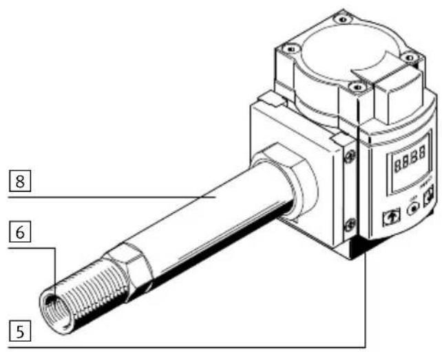
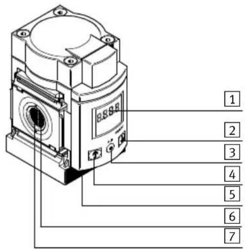
1 2 3 4 5 6 71Display
2B pushbutton
3 Edit button
4A pushbutton
Fig. 1 Operating elements and ports
5 Plug for electrical connection
6 Supply port
7 Laminar flow cartridge
8Stabilizing zone
1.2 Characteristics
| Feature | Order code | Specification |
| Type SFAM Flow sensor | ||
| Grid dimension -62 62 mm | ||
| -90 90 mm | ||
| Flow measuring range -1000 1) | Max. 1000 l/min | |
| -30001) | ||
| -5000 Max. 5000 l/min | ||
| -100002) | ||
| -150002) | ||
| Flow input L Unidirectional from left | ||
| R Unidirectional from right | ||
| Type of mounting -M Manifold assembly | ||
| -T Threaded mounting | ||
| -W1) | ||
| Pneumatic connection G12 1) | G1⁄2 | |
| N121) | ||
| G12) | ||
| N12) | ||
| G1122) | ||
| N1122) | ||
| Electrical output | -2SA | 2x PNP or NPN, 1 analogue output 4 ... 20 mA |
| -2SV | 2x PNP or NPN, 1 analogue output 0 ... 10 mA | |
| Electrical connection | -M12 | Plug connector; M12x1, 5-pin; A-coded |
| Electrical accessories3) | -2.5S | Connecting cable, straight socket, cable length 2.5 m |
| -5S Connecting cable, straight socket, cable length 5 m | ||
| -2.5A | Connecting cable, angled plug socket, cable length 2.5 m | |
| -5 A | Connecting cable, angled plug socket, cable length 5 m | |
1) Only SFAM-62
2) Only SFAM-90
3) Included in the scope of delivery.
Tab. 1 Overview of variants
1.3 Factory settings
| Settings Menu item Value/function | ||
| [SPEC] | ||
| Standard conditions [Option] OFF (=DIN 1343) | ||
| Physical unit for flow rate [FLW] l/min | ||
| Filter time constant [AnA.F] A.60 | ||
| Digital filter [diG.F] d.2 | ||
| Physical unit for consumption [ConS] | l | |
| Switching output | PnP | |
| Security code | [lock] OFF | |
| [OutA] | ||
| Measured variable | FLW (flow rate) | |
| Switching function | [Threshold value comparator] | |
| Switching point | [SP] | 40 % FS |
| Hysteresis | [Hy] | 2 % FS |
| Switching element functions | NO (normally open contact) | |
| Consumption switching impulse | [Ci] | 30 l at FS = 1000 l/min100 l at FS = 3000 l/min150 l at FS = 5000 l/min300 l at FS = 10000 l/min500 l at FS = 15000 l/min |
| [OutB] | ||
| Switching function | [Threshold value comparator] | |
| Switching point | [SP] | 60 % FS |
| Hysteresis | [Hy] | 2 % FS |
| Switching element function | NO (normally open contact) | |
| Change in colour of display | Blue (function deactivated) | |
Tab. 2 Factory settings
2 Function and application
The SFAM is designed to monitor changes in the flow rate and air consumption/air volume for suitable media in piping systems or terminals in industry; for suitable media Chapter 11 Technical data. The design enables stand-alone operation of (SFAM-...-T) or assembly with service units of the MS series (SFAM-...-M).
Measurement is carried out by means of a thermal procedure. Here, the amount of heat drawn from a heated surface of the sensor by the medium flowing past it is calculated. Through the amount of heat removed, the flow rate or accumulated air consumption is determined and shown on the display. The connection to higher-level systems is implemented through 2 binary outputs (Out A/B) and one analogue output (Out C). The switching points for both binary outputs are adjustable for flow rate measurement. To measure air consumption, a consumption switching impulse is adjustable for output
A (Out A). The combination of air consumption measurement (Out A) and flow rate measurement (Out B) is possible. The flow rate value is passed on via the analogue output (Out C).
2.1 Operating statuses

flowchart
graph TD
    A["RUN-Modus"] --> B{IF}
    B --> C["INFO mode EDIT mode TEACH mode RECORDER mode"]
    B --> D["SHOW mode"]
    C --> E["↑"]
    C --> F["↓"]
    D --> G["↑"]
    D --> H["↓"]
    E --> I["EDIT"]
    F --> J["EDIT+"]
    G --> K["EDIT-"]
    H --> L["EDIT+"]
    I --> M["+"]
    J --> N["+"]
    K --> O["+"]
    L --> P["+"]
    M --> Q["+"]
    N --> R["+"]
    O --> S["+"]
    P --> T["+"]
Fig. 2 SFAM operating statuses
RUN mode
In the RUN mode, the following are displayed:
– the measurement values for the flow rate (in l/min or scfm)
– the measurement values for air consumption (in m ^3 , scf or l) and
– the signal statuses of the switching outputs Out A, Out B (set, not set).
INFO mode
In INFO mode, when air consumption measurement is active, the display of input variables (flow rate, air consumption) can be switched quickly in the display. The display can be switched by pressing the A pushbutton or B pushbutton.
SHOW mode
In SHOW mode, the current settings for the switching outputs Out A and Out B, as well as the min/max values for the flow rate or air consumption measurement, are displayed. The min/max values can be reset.
EDIT mode
In EDIT mode, the settings for the flow sensor (switching outputs, standard condition, physical unit, etc.) can be made or changed.
TEACH mode
In TEACH mode, the switching points can be taught.
RECORDER mode
In the RECORDER mode, a manual air consumption measurement can be performed.
2.2 Function range
2.2.1 Switching outputs
Configuration of the switching outputs
Switching output Out A:
This can be done either with the physical input variable flow rate [FLW] or the air consumption measurement [ConS] derived from it.
Switching output Out B:
can only be used with the physical input variable flow rate.
Switching outputs Out A/Out B can be configured according to the setting range in the technical data → Tab. 13.
For the switching output Out A and Out B, the switching function threshold value or window comparator can be selected independently of one another. Each switching output can have the switching element function N/C contact (NC – normally closed) or N/O contact (NO – normally open) separately allocated to it → Tab. 3.
Switching points [SP] and hysteresis [HY] can be set corresponding to the setting ranges in the technical data table → Tab. 13.
Switching point and hysteresis with flow rate measurement for Out A/Out B
| Threshold value comparator Window comparator | ||
| Switching element function NO (normally open contact) | ||
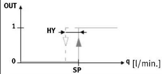 |  | |
| Switching element function NC (normally closed contact) | ||
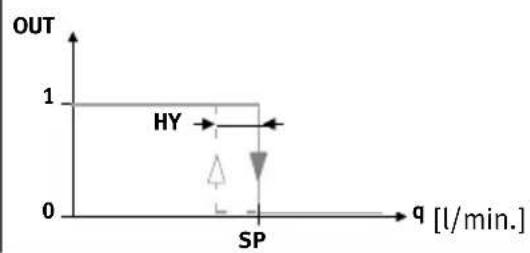 | 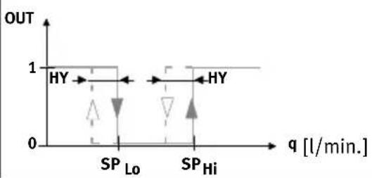 | |
Tab. 3 Switching point SP and hysteresis Hy setting
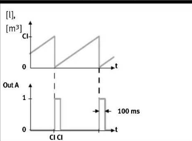
Consumption switching impulse [CI] with air consumption measurement
Setting NO (normally open) Setting NC (normally closed)
line
| Time (ms) | [l], [m³] | Out A | | --------- | --------- | ----- | | 0 | 0 | 0 | | 100 | 1 | 1 | | 200 | 0 | 0 |
line
| Time (ms) | [l], [m³] | Out A | | --------- | --------- | ----- | | 0 | 0 | 1 | | 100 | 1 | 1 | | 200 | 0 | 1 |Tab. 4 Consumption switching impulse
A threshold value for air consumption can be set with the consumption switching impulse [CI]. If the set threshold value is reached, a switching impulse is emitted at the output Out A for 100 ms. With each switching impulse, measurement of the air consumption is started again.
2.2.2 Change in colour
A red colour change can be set for Out B, dependent on the switching status. This allows the system status to be seen across large distances.
The following settings can be chosen:
r.On = Display is red when the switching output is High (1).
Display is blue if the switching output is Low (0).
r.OFF = Display is red when the switching output is Low (0).
Display is blue if the switching output is High (1).
bLUE = Display is always blue; the colour change function is switched off.
2.2.3 Standard conditions
The air mass flow measured and output by the SFAM refers to standard conditions. The SFAM is calibrated at the factory to the physical standard conditions in accordance with DIN 1343 and the unit l/min.

Note
If standard conditions and/or other units that deviate from the calibrated measurement range with the unit l/min are used, there are corresponding characteristic limits for the analogue output Tab. 16 in Chapter 11 Technical data.
The following standard conditions can be selected in the menu item [Option] Chapter 5.5.3 Set special menu [SPEC].
| Option | Off 1 2 | ||
| Standard litres as per DIN 1343 ISO 2533 ISO 6358 | |||
| Air pressure (absolute) [bar] 1.01325 1.01325 1 | |||
| Air pressure (absolute) [kPa] 101.325 101.325 100 | |||
| Temperature [°C] 0 15 20 | |||
Tab. 5 Standard conditions
2.2.4 Analogue filter
With the analogue filter, the filter time constant of all output signals can be changed. This changes the rise time at the analogue output ( Fig. 3).
2.2.5 Digital filter
The display values can be smoothed with the digital filter. The degree of smoothing can be set in 6 steps from d1 = low smoothing to d6=maximum smoothing. With increasing smoothing, the switch-on/switch-off time of the switching outputs rises. In case of d.Off, the switching times depend only on the set filter time constant of the analogue filter ( Fig. 3).
Signal flow from the analogue filter and digital filter

flowchart
graph LR
    A["Sensor Raw signals"] --> B["Analogue filter"]
    B --> C["Digital filter"]
    C --> D["Display"]
    C --> E["Switching outputs Out A/Out B"]
    B --> F["Analogue output"]
Fig. 3 Signal flow from the analogue filter and digital filter
2.2.6 Security code
To protect the setting from unauthorized access, a numerical code of up to 4 digits can be set. The security code must be entered each time the settings are changed (EDIT mode and TEACH mode).
2.2.7 Min/max values
In SHOW mode, the min/max values for a flow rate measurement or an air consumption measurement can be shown and reset Chapter 5.4.

Note
Switching off the supply voltage resets the min/max values.
3 Requirements for product use

Warning
Depending on the functioning of the machine/system, manipulation of signal statuses may cause serious personal injury.
- Note that if the switching characteristics of the outputs are modified in Edit mode, the new characteristics will become effective immediately.
- Enable the password protection option (security code) to prevent accidental alteration by an unauthorised third party Chapter 5.5.3, section "Setting the security code".

Warning
Use of the product in combination with prohibited media can result in personal injury.
- Do not use the product in conjunction with inflammable gases, corrosive gases, oxygen, etc. The product is intended only for measuring the flow rate of the media listed as suitable in Chapter 11 Technical data.

Caution
Condensation water, oil mist, foreign matter and other dirt in the compressed air can damage the product and cause incorrect measurements and malfunctions.
- Make sure that the specified air quality class is maintained for the operating medium Chapter 11 Technical data.

Note
The product is suitable for use only for industrial purposes.
In residential areas, measures for radio interference suppression may be necessary. It is not suitable for commercial invoicing, such as for measurement of air consumption in public utilities.
- Compare the limit values specified in these operating instructions with those of your actual application (e.g. operating media, pressures, forces, torques, temperatures, loads, speeds, operating voltages, flow rates).
• Take the ambient conditions at the location of use into consideration. - Remove all transport packing, such as protective wax, foils (polyamide), caps (polyethylene), cardboard boxes (except for the sealing elements of the pneumatic connections).
The material used in the packaging has been specifically chosen for its recyclability (exception: oiled paper = residual waste). - Use the product in its original status. Unauthorised modification is not permitted.
4 Installation
4.1 Mechanical/pneumatic installation
The mounting position is horizontal ±5 %. Mount the SFAM as follows:

natural_image
Technical line drawings of two mechanical components with directional arrows indicating assembly or movement (no text or symbols present)Fig. 4 Mechanical/pneumatic installation

Note
Information about mounting of the module connector, sub-base and mounting bracket (mounting bracket only for SFAM-62) can be found in the operating instructions enclosed with the relevant accessories.
The air mass flow is routed to the connection at which the laminar flow cartridge (for SFAM-...-M) or the stabilising zone (for SFAM-...-T/-W) is located. The air mass flow is taken from the opposite connection ( Fig. 4).
Minimum requirements of pneumatic connection
Depending on the grid dimension, the following minimum requirements are to be observed for the pneumatic connection:
| SFAM MS series pneumatic connection Internal supply line diameter [mm] | |
| -62 1/2” 10 | |
| -90 3/4” 20 | |
Tab. 6 Minimum requirements of pneumatic connection
Assembly with MS series service units
When assembled with an existing service unit of the MS series:
- Observe the flow direction.
- Install the SFAM only after installing service units which conform to the degree of filtration (air quality class 7.4.4.: 40 m residual dust, +3^ C pressure dew point, 1 mg / m^3 residual oil content).

Note
The compressed air must not contain ester oils.

Note
The SFAM must not be installed directly behind a pressure regulator or filter regulator to comply with the specified accuracies.
- After the filter regulator MS...-LFR or pressure regulator MS...-LR, build a branching module upstream of SFAM.
- Grid dimension 62: MS...-FRM- 1/2
-
Grid dimension 90: MS...-FRM- 3/4
-
Place the module connectors type MS...-MV in the slots of the individual devices. Accordingly, a seal is required between the individual devices.
- Fasten the module connectors type MS...-MV with 2 screws.
4.2 Electrical connection

Warning
Only use power sources which guarantee reliable electrical isolation of the operating voltage according to IEC/DIN EN 60204-1. Also observe the general requirements for PELV power circuits according to IEC/DIN EN 60204-1.
Switched-mode power supplies are permitted, provided that they ensure reliable separation in accordance with EN 60950/VDE 0805.

Note
Long signal lines pick up more interference.
- Make sure that the signal lines are always shorter than 30 m.

Note
The binary outputs at pin 2 and pin 4 can be wired as PNP or NPN connections as needed.
- Make sure that you also configure the binary outputs according to your wiring Chapter 5.5.3.
- Wire the SFAM as follows:
| Pin | Allocation Core colours | 1) | Plug connectors2) |
| 1 | +24 V DC operating voltage | Brown (BN) | 5-pin M12 |
| 2 Binary output B (Out B) White (WH) | |||
| 3 0 V Blue (BU) | |||
| 4 Binary output A (Out A) Black (BK) | |||
| 5 Analogue output C (Out C) 3) | Grey (GY) |
1) Using the connecting cable from the electrical accessories Chapter 1.2 Key features
2) Tightening torque for the union nut at the plug connector is max. 0.5 Nm.
3) Voltage U or current I → Chapter 11 Technical data
Tab. 7 Pin allocation
| Circuit diagrams | ||
| SFAM-...-2SA SFAM-...-2SV | ||
 |  | |
Tab. 8 SFAM circuit diagrams
5 Commissioning
5.1 Symbols on the display
| Symbols | Description |
| Out A/Out B | Switching output A/switching output B |
| Lock | Security code active (blocked against unauthorised programming) |
| Run | Accumulated air consumption measurement is active in RECORDER mode. |
| Option | The sensor is set to a standard condition that differs from the factory setting.→ Chapter 5.5.3 Setting standard conditions [option] section |
| Stop | Reset air consumption measurement value |
| Switching output set/not set | |
| Threshold value comparator | |
| Window comparator | |
| Con5 | Air consumption switching mode (consumption – only for Out A) |
| Symbols Description | |
| CI | Trigger level for consumption switching impulse (consumption impulse) |
| SP | Switching point |
| SPLo | Lower switching point (switching point – low) |
| SPH, | Upper switching point (switching point – high) |
| HY | Hysteresis |
| no | Contact (normally open) |
| nc | Contact (normally closed) |
| FLUJ | Switching mode flow rate (flow – only for Out A) |
| FLo | Minimum flow rate (flow low) |
| FH, | Maximum flow rate (flow high) |
| SPEC | Special menu |
| AnAF | Analogue filter |
| dIGF | Digital filter |
| rOn | Display red with switching status ON and/or logic 1 (for Out B) |
| rOFF | Display red with switching status OFF and/or logic 0 (for Out B) |
| PnP | Positive switch output |
| nPn | Zero switch output |
| ■■■■□□□□□ | Segments illuminated: Graphic display of the current measured value related to the maximum measured value of the measuring range |
| □□■□□□□□□ | Running light (1 segment): Air consumption measurement for Out A or RECORDER mode active |
| □□■□□□□□ | 3 segments flash: Hysteresis value is displayed |
| □□□□□□□□□ | 1 segment flashes:– Segment 6: Switching point SP or SP.Lo is displayed– Segment 8: Switching point SP.Hi is displayed– Segment 1: Min. flow rate (F.Lo) is displayed– Segment 10: Max. flow rate (F.Hi) is displayed |
Tab. 9 Symbols on the display
5.2 Symbols for representing the menu structure
| Symbol Significance | |
| (Timeout)→80s | Automatic return to the basic status (RUN mode) when the monitoring time has expired (here 80 seconds) |
| EDIT(Cancel)→3s | In order to return manually to the basic status (RUN mode), press the EDIT button for 3 seconds |
| Flow 1 | Generate flow rate (for teaching the measured value – here Flow 1) |
Symbol Significance
Symbol Significance
 | The symbol on the display flashes (here: Out B) |
| Security code active (lock – blocked against unauthorised programming) | |
| Security code inactive (Lock) | |
| Press pushbutton (here: A pushbutton). | |
| Press the A pushbutton or B pushbutton. The SFAM then switches to the setting indicated by the arrow. | |
| Press the A pushbutton and B pushbutton simultaneously | |
| Press pushbutton (here A pushbutton) and the EDIT button simultaneously | |
 | Press A pushbutton or B pushbutton and thus set the desired value |
 | A momentary display (here [ANA.F]) means that a value can be displayed. |
 | Display for a value or switching point. Value can be set. |
| Edit | Press the Edit button |
 | Branch in the menuThe setting last selected in the EDIT mode is indicated in the SHOW mode |
Tab. 10 Symbols for representing the menu structure
5.3 RUN mode
In the basic status, the product is in RUN mode. The current measured value is displayed. The basic status can be reached from other modes by:
- Pressing the Edit button for 3 seconds or
- Expiration of a monitoring time, timeout
In the RUN mode, the following are displayed:
– the measurement values for the flow rate (in l/min or scfm)
– the measurement values for air consumption (in m^3 , scf or l) and
– the signal statuses of the switching outputs Out A, Out B (set, not set).
- Switch on the operating voltage.
The SFAM is in RUN mode.
- Check the SFAM settings → Chapter 5.4 SHOW mode.

Note
A flashing value means that the value was measured outside the permissible measuring range.
5.4 INFO/SHOW mode

flowchart
System flowchart for RUN-Modus and SHOW Modus modules, showing signal processing paths with IF, FLU, SP, and Clear conditions.1) INFO mode only possible when consumption measurement is active
Fig. 5 SHOW mode
In Show mode, depending on whether the A or B pushbutton is pressed, the current settings for the switching outputs Out A or Out B will be shown.
The SFAM must be in RUN mode.
- When air consumption measurement is activated, the INFO mode enables rapid changeover of the input variables flow rate and air consumption in the display by pressing the A or B pushbutton.

Note
If there are errors, pressing the A pushbutton/B pushbutton first displays corresponding error numbers.
- Repeated pressing of the A pushbutton/B pushbutton displays the settings of the respective switching output one after another.
- At the end of SHOW mode, the min value [F.Lo] and max value [F.Hi] are displayed. If no further buttons are pressed, the display remains constant (no timeout). The min and/or max display is thereby signaled by the flashing of segment 1 or segment 10 in the bar graph Tab. 9.
- The min/max values can be reset by pressing the Edit button.
- When all settings have been displayed, the SFAM goes back into RUN mode when the A pushbutton/B pushbutton are pressed again and displays the current measurement value for the corresponding output.
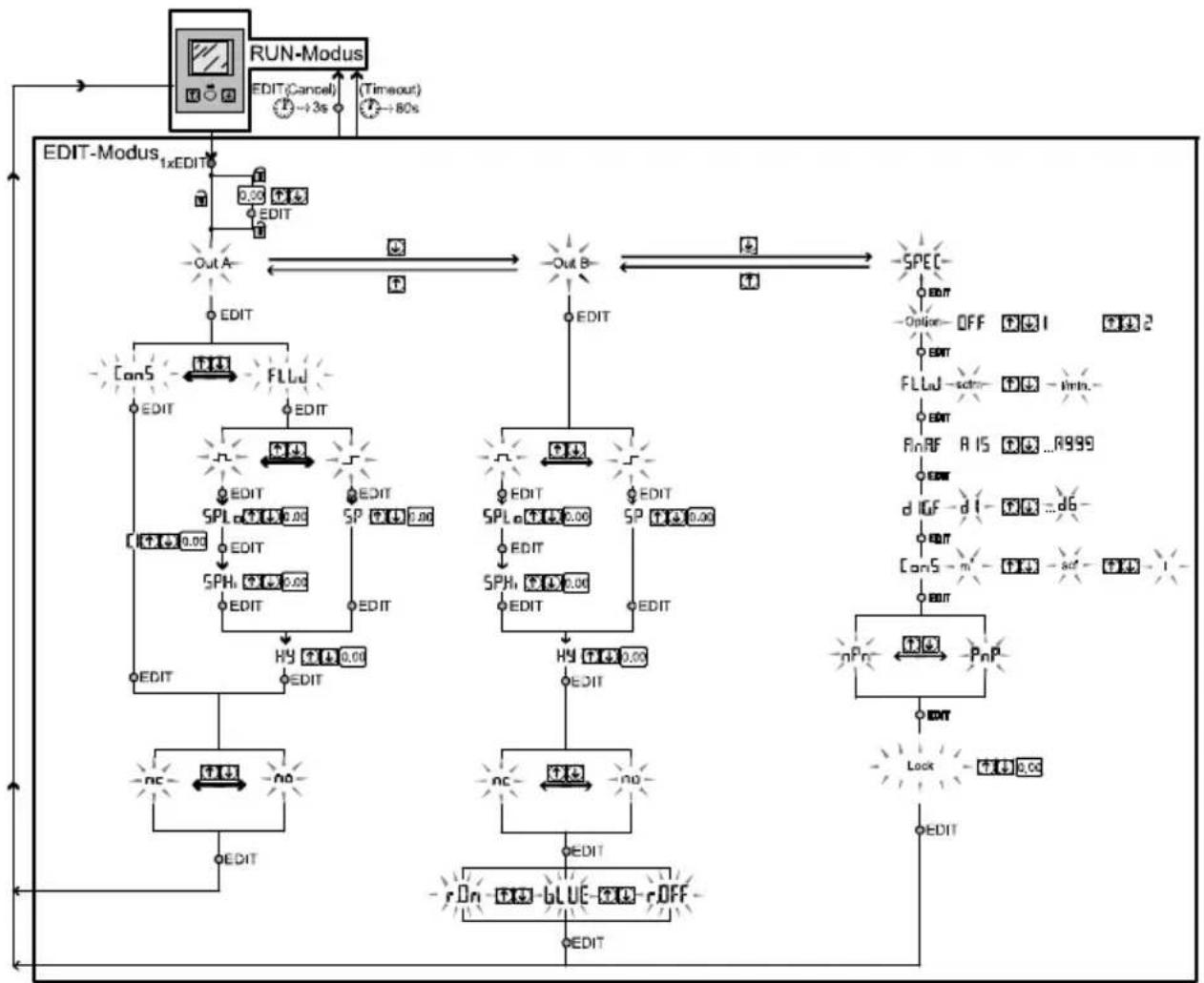
5.5 EDIT mode
flowchart
graph TD
    A["RUN-Modus"] --> B["EDIT-Modus"]
    B --> C["1xEDIT"]
    C --> D["EDIT-Cancel"]
    D --> E["→3s"]
    E --> F["(-Timeout)"]
    F --> G["→80s"]
    G --> H["OUT A"]
    H --> I["EDIT"]
    I --> J["CanS"]
    J --> K["FLU"]
    K --> L["EDIT"]
    L --> M["EDIT"]
    M --> N["SPL"]
    N --> O["EDIT"]
    O --> P["SPH"]
    P --> Q["EDIT"]
    Q --> R["HY"]
    R --> S["EDIT"]
    S --> T["NC"]
    T --> U["+"]
    U --> V["NO"]
    V --> W["EDIT"]
    W --> X["r On"]
    X --> Y["BLUE"]
    Y --> Z["r OFF"]
    Z --> AA["EDIT"]
    AA --> AB["OUT B"]
    AB --> AC["SPEC"]
    AC --> AD["EDIT"]
    AD --> AE["-Option- OFF"]
    AE --> AF["FLLU"]
    AF --> AG["-strn-"]
    AG --> AH["RnRF"]
    AH --> AI["RIS"]
    AI --> AJ["-...R999"]
    AJ --> AK["EDIT"]
    AK --> AL["dUF"]
    AL --> AM["-dI-"]
    AM --> AN["-act-"]
    AN --> AO["-1-"]
    AO --> AP["EDIT"]
    AP --> AQ["nPn"]
    AQ --> AR["PnP"]
    AR --> AS["EDIT"]
    AS --> AT["Lock"]
    AT --> AU["+4 0.00"]
    AU --> AV["EDIT"]
Fig. 6 EDIT mode
5.5.1 Start EDIT mode
In the EDIT mode, you can configure settings for the switching output Out A, the switching output Out B and the special menu [Spec].

Warning
Manipulation of signal statuses may cause serious personal injury, depending on the functioning of the machine/system.
- Note that if the switching status of the outputs is modified in EDIT mode, the new status will be effective immediately.
- Press the Edit button.
The EDIT mode is active and [Out A] flashes or, if there is an active security lock, [Lock] flashes.
-
Press the A/B pushbuttons until the chosen security code is set.
-
Press the Edit button.
The EDIT mode is active and [Out A] flashes.
- Press the A/B pushbutton to switch between the setting modes for Out A, Out B and the special menu.
5.5.2 Setting the switching characteristics of the switching outputs
a) Set flow rate monitoring

Note
The process for setting the switching outputs is fundamentally the same. Additionally, the switching mode [FLW] must be selected for Out A since Out A can also be configured for air consumption measurement. For Out B, the colour change for the display can also be set.
In the following, the process is described using the switching output Out A.
The SFAM is in the EDIT mode and [Out A] flashes, → Chapter Start EDIT mode.
- To set Out A, proceed as follows:
- Press the Edit button to confirm the selection.
[FLW] or [ConS] flashes.
-
Select the flow rate measurement (FLW) with the A/B pushbutton.
-
Press the Edit button to confirm the selection.
The currently set switching function flashes.
-
Select the desired switching function with the A/B pushbuttons.
-
Press the Edit button to confirm the selection.
[SP] or [SP.Lo] flashes.
-
Set the switching point (SP or SP.Lo) with the A/B pushbuttons.
-
Press the EDIT button to confirm the set value.
Only with window comparator switching function.
[SP.Hi] flashes
- Set the value (SP.Hi) with the A/B pushbuttons.
- Press the EDIT button to confirm the set value.
[Hy] flashes.
-
Set the value for the hysteresis (Hy) by using the A/B pushbuttons.
-
Press the EDIT button to confirm the set value.
[NO] or [NC] flashes.
-
Select the switching element function (NO/NC) with the A/B pushbuttons.
-
Press the EDIT button to confirm the set value.
Only for Out B (Set colour change)

Note
If the flow rate monitoring has been configured for Out B, the colour change can be configured for the display after configuration of the switching element function.
[rON], [rOFF] or [bLUE] flashes. The setting for the colour change can be configured.
-
Select the desired setting (rON, rOFF or bLUE) with the A/B pushbutton.
-
Press the Edit button to confirm the selection.
The SFAM is in RUN mode.
Carry out a test run with various flow rates to ascertain whether the SFAM switches as desired (switching points and hysteresis).
b) Set consumption monitoring

Note
Air consumption measurement [ConS] can be activated for switching output Out A.
The SFAM is in the EDIT mode and [Out A] flashes → Chapter Start EDIT mode.
- Press the Edit button to confirm the selection.
[FLW] or [ConS] flashes.
-
Select the air consumption measurement [ConS] with the A/B pushbuttons.
-
Press the Edit button to confirm the selection.
[Cl] flashes.
-
Set the value for the consumption impulse (CI) with the A/B pushbuttons.
-
Press the EDIT button to confirm the set value.
[NO] or [NC] flashes.
-
Select the switching element function (NO/NC) with the A/B pushbuttons.
-
Press the EDIT button to confirm the set value.
The SFAM is in RUN mode
Carry out a test run with various flow rates to ascertain whether the SFAM switches as desired.
5.5.3 Set special menu [SPEC]
This is how you reach the special menu:
The SFAM is in the EDIT mode and [Out A] flashes, Chapter Start EDIT mode.
- Press the A or B pushbutton until the menu (SPEC) is selected.
[SPEC] flashes.
- Press the Edit button to confirm the selection.
[Option] flashes, the standard conditions (OFF, 1 or 2) can be set.
Set standard conditions [Option]
-
Select the desired setting (OFF, 1 or 2) with the A/B pushbuttons.
-
Press the Edit button to confirm the selection.
[FLW] is displayed and the currently chosen value flashes.
The unit for the flow rate (l/min or scfm) can be set.
Setting the physical unit for the flow rate [FLW]
-
Select the desired setting (l/min or scfm) with the A/B pushbuttons.
-
Press the Edit button to confirm the selection.
[AnA.F] and the currently set value are displayed. The analogue filter can be set.
![Festo SFAM-90-10000L-TG112-2SV-M12 - Setting the physical unit for the flow rate [FLW] - 1](/content/2026/06/1227731/images/99be45254ebfdbdbf8d9a8a0c0b6984ec5bb1c54952096e881ddf6c96f5b1e40.jpg)
Note
The configured physical unit is shown in RUN mode in the display at the bottom right.
Set analogue filter [AnA.F]
- Select the value for the filter time constants (15 ms, 30 ms, 60 ms, 125 ms, 250 ms, 500 ms or 999 ms) with the A/B pushbuttons.
- Press the EDIT button to confirm the set value.
[dIG.F] and the currently selected value flash. The digital filter can be set.
Set smoothing for the digital filter [diGF]
![Festo SFAM-90-10000L-TG112-2SV-M12 - Set smoothing for the digital filter [diGF] - 1](/content/2026/06/1227731/images/71d8d9a29cbf1c4e75c20f0fdc28c230f795b865a68e30f7462036a0caab10b1.jpg)
Note
A high filter time constant and high smoothing can result in a switching time of several seconds.
- Select the value for cushioning (d1 to d6 or d.OFF) with the A/B pushbuttons.
- Press the EDIT button to confirm the set value.
[ConS] is displayed and the currently selected value flashes.
The unit for the air consumption ( m^3 , scf or l) can be set.
Set the physical unit for the air consumption [ConS]
- Select the desired setting ( m^3 , scf or l) with the A/B pushbuttons.
- Press the Edit button to confirm the selection.
The currently set value [PnP] or [nPn] for the switching element output flashes. The switching element output can be set.
Set switching output characteristic [PnP] or [nPn]
- Select the desired setting (PNP or NPN) with the A/B pushbuttons.
- Press the Edit button to confirm the selection.
[Lock] flashes. The current setting is then displayed.
Setting the security code

Note
Keep the security code where it can be found. If the security code has been forgotten see, the Chapter 6 Resetting SFAM to factory setting.
- Use the A/B pushbuttons to select between an inactive security code (OFF) or a maximum 4-digit security code.
- Press the Edit button to confirm the selection.
The SFAM is in RUN mode.
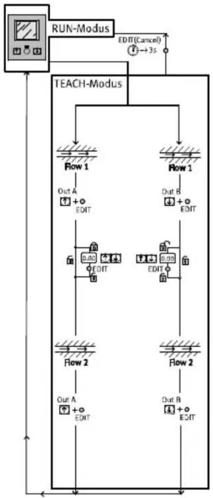
5.6 TEACH mode

Note
The process is the same for teaching the switching outputs Out A (A button) and Out B (B button). In the following, the process is described using the switching output Out A.
flowchart
graph TD
    A["RUN-Modus"] --> B["TEACH-Modus"]
    B --> C1["Flow 1"]
    B --> C2["Flow 1"]
    C1 --> D1["Out A + EDIT"]
    C2 --> D2["Out B + EDIT"]
    C1 --> D3["0.00 EDIT"]
    C2 --> D4["0.00 EDIT"]
    C1 --> D5["Flow 2"]
    C2 --> D6["Flow 2"]
    D5 --> E1["Out A + EDIT"]
    D6 --> E2["Out B + EDIT"]
    D1 --> F1["EDIT(Cancel)"]
    D2 --> F2["EDIT"]
    D3 --> F3["EDIT"]
    D4 --> F4["EDIT"]
    D5 --> F5["EDIT"]
    D6 --> F6["EDIT"]
    F1 --> G1["→3s"]
    F2 --> G2["→3s"]
    F3 --> G3["→3s"]
    F4 --> G4["→3s"]
    F5 --> G5["→3s"]
Fig. 7 TEACH mode
In TEACH mode, the switching points for flow rate monitoring can be programmed.
- Before teaching in EDIT mode, select the desired switching function (threshold value or window comparator) Chapter 5.5. EDIT mode.
Threshold value comparator Window comparator
| The (taught) switching point is derived from the average value of both measured valuesSP = 1/2(Flow 1 + Flow 2)Special case: SP = Flow 1 = Flow 2 | The taught switching window is derived from the measured values:SP.Lo = Flow 1SP.Hi = Flow 2 |
Tab. 11 Set switch variable
For teaching the switching variables:
-
Generate a flow rate (Flow1)
-
First press the A pushbutton and then also the Edit button.
[Out A] and bar graph flash and the measurement value is assumed as the first teach point or [Lock] flashes if the security lock is active.
Only with active security blocking [Lock] (points 4 and 5):
-
Press the A/B pushbuttons until the chosen security code is set.
-
Press the Edit button.
[Out A] and the bar graph flash and the measurement value is assumed as the first teach point.
-
Generate a second flow rate (Flow 2).
-
First press the A pushbutton and then also the Edit button.
The second teach point is assumed and the switching point (SP) or switching points (SP.Lo and SP.Hi) become valid.
The SFAM is in RUN mode.
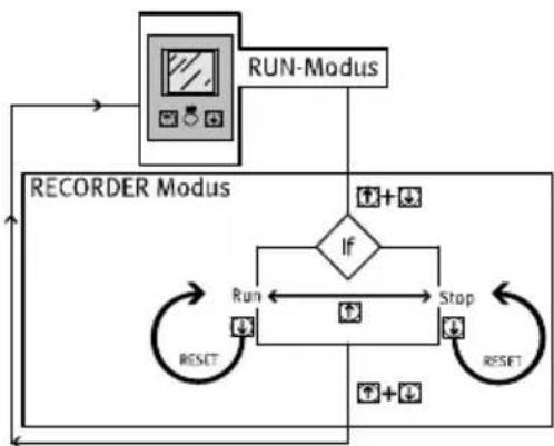
5.7 RECORDER mode
In the RECORDER mode, a manual air consumption measurement can be performed.
flowchart
graph TD
    A["RUN-Modus"] --> B["If"]
    B --> C["Run"]
    B --> D["Stop"]
    C --> E["RESET"]
    D --> F["RESET"]
    G["RECORDER Modus"] --> B
    G --> C
    G --> D
Fig. 8 RECORDER mode
- Press the A and B pushbuttons simultaneously.
The SFAM is in RECORDER mode
The status of the measurement [Run] or [Stop] is displayed.
-
The measurement can be started or stopped by pressing the A pushbutton.
-
By pressing the B pushbutton, you can reset the measurement to zero.
-
Press the A and B pushbuttons simultaneously.
The SFAM is in RUN mode.

Note
If the RECORDER mode is exited during an ongoing measurement [Run], the measurement will continue in the background.
6 Operation

Caution
Excessive internal heat will destroy the SFAM.
- Avoid high cycle rates with large pressure amplitudes. Otherwise, the admissible limiting temperatures of the used materials will be exceeded.
The air mass flow displayed by the SFAM refers to the standard conditions that were set under “Options” in the special menu.
When comparing volumetric flow rates:
- Make sure that the volumetric flow rates to be compared (e.g. operating volume flow rate, amount supplied by a compressor, measured values of a flow sensor from another manufacturer) refer to the same initial conditions.
- After the supply voltage is switched on, the SFAM needs a warm-up time of 5 minutes until it achieves the specified accuracy.
Reset SFAM to factory setting
(even if the security code cannot be found)

Note
By resetting to factory settings, the current settings are lost. If required, make a note of these settings before resetting.
To reset the SFAM to the factory setting, proceed as follows:
-
Switch off the operating voltage.
-
Press and hold all three setting elements (A pushbutton + B pushbutton + the Edit button) at the same time.
-
Switch the operating voltage off and then on again.
The SFAM is in RUN mode.
7 Maintenance and care
- Switch off the following energy sources before cleaning the exterior of the device:
- Operating voltage
- Compressed air.
- If necessary, clean the SFAM from the outside.
Soap suds (max. +60 °C), petroleum ether and all non-abrasive cleaning agents may be used.
8 Disassembly
-
Switch off the following energy sources before disassembly:
-
Operating voltage
-
Compressed air
-
Disconnect the respective connections from the SFAM.
9 Fault clearance
| Malfunction Possible cause Remedy | ||
| Incorrect measured value indicator | SFAM operated with non-permitted medium | Operate SFAM only with permitted media |
| SFAM contaminated Replace device | ||
| In case of flow rate measurement: Measured value is flashing | Measurement outside permitted measuring range | Accuracy refers only to the permitted measuring range |
| In case of air consumption measurement: Measured value is flashing | Measuring range end value has been exceeded at least once. Specified accuracy can therefore probably not be maintained | Make sure that the measuring range end value is not exceeded |
| Outputs do not switch corresponding to the setting | Short circuit or overload at corresponding output | Eliminate short circuit/overload |
| Settings cannot be edited (Lock) | Access protection active Entering the security code | |
| O.FLO Measurement range exceeded (displayed in RUN mode) | Check operating conditions | |
| Er1, Er2, Er4 Device defective Replace device | ||
| Er9 Measurement range undershot (displayed in SHOW mode) | Check operating conditions | |
| Er10 Measurement range exceeded (displayed in SHOW mode) | Check operating conditions | |
| Er17 | Undervoltage | Maintain operating voltage |
| Check electrical wiring | ||
Tab. 12 Fault clearance
10 Accessories
Please select the corresponding accessories from our catalogue.
→ www.festo.com/catalogue/sfam
11 Technical data
| SFAM -1000 -3000 -5000 -10000 -15000 | |||||
| General information | |||||
| Certification certificate RCM Mark, cULus – Recognized (OL) | |||||
| CE marking(→ Declaration of conformity) | According to EU EMC Directive | ||||
| Note on materials RoHS-compliant | |||||
| Input signal/measuring element | |||||
| Measured variable Flow rate, air consumption | |||||
| Flow direction -L Unidirectional P1 } P2-R Unidirectional P1 { P2 | |||||
| Measuring principle Thermal | |||||
| Flow measuring range [l/min.] | 10 ... 1000 | 30 ... 3000 | 50 ... 5000 | 100 ... 10000 | |
| Operating pressure [bar] | 0 ... 16 | ||||
| Operating pressure [MPa] | 0 ... 1.6 | ||||
| Nominal pressure [bar] | 6 | ||||
| Nominal pressure [MPa] | 0.6 | ||||
| Operating medium Air quality class | 7:4:4 according to DIN ISO 8573-1 | ||||
| Nitrogen | |||||
| Temperature of medium [°C] | 0 ... 50 | ||||
| Ambient temperature [°C] | 0 ... 50 | ||||
| Nominal temperature [°C] | 23 | ||||
| Signal processing | |||||
| Filter time constant [ms](analogue filter) | [ms] | Possible settings: 15, 30, 60 (factory setting), 125, 250, 500, 999 | |||
| Filter time constant [ms](digital filter) | [ms] | d.OFF, d1 ... d6 (factory setting: d2)d1: approx. 20d2: approx. 40d3: approx. 80d4: approx. 160d5: approx. 320d6: approx. 640 | |||
| Output, general ^1)^2) | |||||
| Accuracy of zero point [%] ±FS ^4) | [%] | 0.3 | |||
| Accuracy range ±FS ^4) | [%] | 3 | |||
| Repetition accuracy, [%]zero point ±FS | [%] | 0.2 | |||
| Repetition accuracy [%]range ±FS | [%] | 0.8 | |||
| SFAM -15000-10000-5000-3000-1000 | |||||
| Temperature coefficient [%] typ. range ±FS/K | 0.1 | ||||
| Pressure dependency [%] 0.5 range ± FS/bar | |||||
| Pressure dependency [%] 0.5 range ± FS/100 kPa | |||||
| Switching output | |||||
| Switching output 2x PNP or 2x NPN, adjustable | |||||
| Switching function Window comparator or threshold value comparator, adjustable | |||||
| Switching element function N/C or N/O contact, adjustable | |||||
| Max. output current [mA] 100 | |||||
| Voltage drop [V] Max. 1.5 | |||||
| Inductive protective circuit | Adapted to MZ, MY, ME coils | ||||
| Analogue output | |||||
| Characteristic curve for [l/min.] flow rate | 0 ... 1000 | 0 ... 3000 | 0 ... 5000 | 0 ... 10000 | 0 ... 15000 |
| Output characteristic [mA] 4 ... curve for current | 20 | ||||
| Output characteristic [V] 0 ... 10 curve for voltage | |||||
| Max. load resistance of [Ohm] current output | 500 | ||||
| Min. load resistance of [kOhm] Voltage output | 10 | ||||
| Output, additional data | |||||
| Short circuit protection | Yes | ||||
| Overload protection | Present | ||||
| Electronics | |||||
| Operating voltage range DC [V] 15 ... | 30 | ||||
| Protection against incorrect polarity | For all electrical connections | ||||
| Electromechanics | |||||
| Electrical connection | Straight plug, M12x1, 5-pin | ||||
| Max. length of [m] connecting cable | <30 | ||||
| Mechanics | |||||
| Installation position | Horizontal ±5° | ||||
| Pneumatic connection | G 12 | G 12 | G 12 | - | |
| Grid dimension 62 for SFAM-...-T | NPT 12 | NPT 12 | NPT 12 | - | |
| Pneumatic portGrid dimension 90 for SFAM-...-T | -- G1 G1 G1 | ||||
| -- NPT1 NPT | 1 NPT1 | ||||
| -- G1 12 G1 12 | 2G1 12 | ||||
| -- NPT1 12 NPT | 1 12 NPT1 12 | ||||
| Product weight [g]- SFAM-62-...-M 600 600 600 -- - SFAM-62-...-T - SFAM-92-...-M -- 1500 1500 1500 - SFAM-92-...-T | 100 1100 | 1100 -- | |||
| 0 | |||||
| - 2400 2750 | 2750 | ||||
| Information on housing materials | Reinforced polyamide/die-cast aluminium | ||||
| Display/operation | |||||
| Display type | Illuminated LCD, blue | ||||
| Displayable units | l/min, scfm,l, m3, scf | ||||
| Setting range for flow rate threshold value | 1%FS ... 100 %FS | ||||
| Setting range for consumption impulse threshold value [l] | 3 ... 19999 | 10 ...19999 | 15 ...19999 | 30 ...19999 | 50 ...19999 |
| [m3] | 1 ... 19999 | ||||
| [scf] | 0.1 ...1999.9 | 0.4 ...1999.9 | 0.5 ...1999.9 | 1 ... 1999.9 | |
| Hysteresis setting range | 0%FS ... 90 %FS | ||||
| Immissions/emissions | |||||
| Storage temperature [°C] | -20 ... +80 | ||||
| Degree of protection | IP65 | ||||
| Pressure drop ^3) [mbar] | < 100 | < 200 | |||
| Pressure drop ^3) [kPa] | < 10 | < 20 | |||
| Protection class | III | ||||
1) Accuracy with nominal conditions (6 bar (0.6 MPa), 23 °C and horizontal mounting position)
2) % FS = % of the measuring range end value (full-scale)
3) Measured at a flow rate of 50 %FS
4) Calculation examples → p. 33
Tab. 13 Technical data
Flow measuring range ^1) qn as a function of operating pressure p
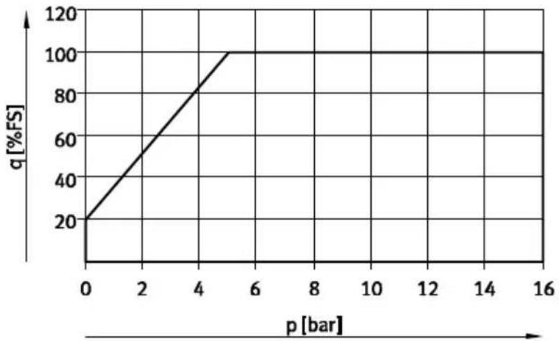
line
| p [bar] | q [%FS] | | ------- | ------- | | 0 | 20 | | 5 | 100 |Fig. 9 Specific flow rate range
1) Within the flow rate measurement range the precision specifications apply in accordance with Tab. 13
Dimensions SFAM-62
Manifold assembly SFAM-...-M

text_image
B1 B2 B3 H4 H H2 1 2 2 4 1 31 Plug connector M12x1 according to EN 60947-5-2
2 LCD
3 Connecting cable, straight socket
4 Connecting cable, angled plug socket
Threaded mounting SFAM-62-...-T/W

text_image
B4 B6 B7 H2 D1 H5 D3 B5 A 3 Z H6 B7 65 Stabilizing zone
6 Wall fastener
(only with type of mounting -W)
Fig. 10 Dimensional drawing
| Type B1 B2 B3 B4 B5 B6 B7 D1 | ||||||||
| SFAM-62-...-M 62 31 | 78.7--- | -- | ||||||
| SFAM-62-...-TG12 62 | 31 78.7 2 | 77 40--G ^1/2 | ||||||
| SFAM-62-...-WG12 61 | 1.9 4.5 | |||||||
| SFAM-62-...-TN12 62 | 31 78.7 2 | 77 40--NPT ^1/2 | ||||||
| SFAM-62-...-WN12 61 | 1.9 4.5 | |||||||
| Type | D3 | H1 | H2 | H4 | H5 | H6 | |
| SFAM-62-...-M | - | 63.5 | 62.1 | 80 | - | - | - |
| SFAM-62-...-TG12 | G^3/4 | 63.5 | 62.1 | 80 | - | - | 26 |
| SFAM-62-...-WG12 | 71 | 6.6 | |||||
| SFAM-62-...-TN12 | NPT^3/4 | 63.5 | 62.1 | 80 | - | - | 26 |
| SFAM-62-...-WN12 | 71 | 6.6 | |||||
Tab. 14 Dimension table SFAM-62
Dimensions SFAM-90
Manifold assembly SFAM-...-M

1 Plug connector M12x1 according to EN 60947-5-2
2 LCD
3 Connecting cable, straight socket
4 Connecting cable, angled plug socket
Threaded mounting SFAM-...-T
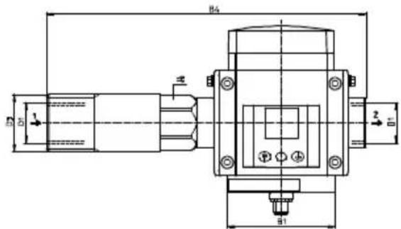
text_image
B4 B5 1 2 3 B1Fig. 11 Dimensional drawing SFAM-90
| Type B1 B2 B3 B4 D1 | |||||
| SFAM-90-...-M 90 45 | 109 -- | ||||
| SFAM-90-...-TG1 | 90 45 109 | 267 G1 | |||
| SFAM-90-...-TG112 | 301 G112 | ||||
| SFAM-90-...-TN12 | 90 45 109 | 267 NPT1 | |||
| SFAM-90-...-TN112 | 301 NPT112 | ||||
| Type D3 H1 H2 H4 = | |||||
| SFAM-90-...-M - 76.5 | 81.3 93 - | ||||
| SFAM-90-...-TG1 | G1 12 | 76.5 81.3 93 | 41 | ||
| SFAM-90-...-TG112 | G2 | 55 | |||
| SFAM-90-...-TN12 | NPT1 12 | 76.5 81.3 93 | 41 | ||
| SFAM-90-...-TN112 | NPT2 | 55 | |||
Tab. 15 Dimension table SFAM-90
Characteristic curve for the analogue output
| Option | Factor | Unit | Analogue output | |||||
| 0 V or 4 mA | 10 V or 20 mA | |||||||
| Lower limit | Upper limit | |||||||
| Standard conditions in accordance with DIN 1343 (1.01325 bar, 101.325 kPa, 0 °C) | ||||||||
| OFF | 1 | [l/min.] | 0 | 1000 | 3000 | 5000 | 10000 | 15000 |
| [scfm] | 0 | 35.31 | 105.9 | 176.6 | 353.1 | 529.7 | ||
| Standard conditions in accordance with ISO 2533 (1.01325 bar, 101.325 kPa, 15 °C) | ||||||||
| 1 | 1.055 | [l/min.] | 0 | 1055 | 3165 | 5275 | 10550 | 15825 |
| [scfm] | 0 | 37.25 | 111.8 | 186.3 | 372.5 | 558.8 | ||
| Standard conditions in accordance with ISO 6358 (1 bar, 100 kPa, 20 °C) | ||||||||
| 2 | 1.087 | [l/min.] | 0 | 1087 | 3261 | 5435 | 10870 | 16305 |
| [scfm] | 0 | 38.38 | 115.15 | 191.91 | 383.8 | 575.7 | ||
Tab. 16 Characteristic curve for the analogue output
Example calculations for calculating the maximum occurring characteristic curve deviation: In the display of SFAM-1000U, a measurement value of 600 l/min will be shown for the flow rate. How large can the actual, true flow rate that flows through the sensor be?
SFAM
According to the specification the following apply for nominal conditions (6 bar, 0.6 MPa, 23 °C):
- Accuracy range: ±3 %FS
- Accuracy of zero point: ±0.3 %FS.
- (in example: FS = 1000 l/min)
The overall error during nominal conditions is made up of both of these error variables, which in the following will be considered separately.
a) Range error
A range error of the measurement signal (= error in the slope of the characteristic curve) has a stronger effect the larger the measurement value is ( Fig. 12). A range error can be designated a sensitivity or slope error.

line
| FS | x [l/min] | y [l/min] | |------|-----------|-----------| | 1000 | 600 | 600 | | 1000 | 1000 | 1000 |x = measured variable (flow rate)
y = measurement value (display)
z = display value error sought
Fig. 12 Range error
The maximum error results from the largest full-scale measured value (in the example FS = 1000 l/min). According to the specification, the error is specified at ±3 %FS.
The maximum error is calculated as follows:
$$ \pm 3 \% \mathrm{FS} = \pm 3 \% \times 1000 \mathrm{l} / \min = \pm 3 / 100 \times 1000 \mathrm{l} / \min = \pm 30.00 \mathrm{l} / \min $$
If a measurement value of 600 l/min is displayed, the maximum range error is calculated as follows:
$$ \pm 3 0 \mathrm{l} / \min \times (6 0 0 \mathrm{l} / \min) / (1 0 0 0 \mathrm{l} / \min) = \pm 1 8 \mathrm{l} / \min $$
Because of the range error, with a display of 600 l/min at the sensor, the actual flow rate through the sensor values can have values in the range 582 ... 618 l/min.
Along with the range error, the zero point error must still be taken into account.
b) Zero point error
A zero point error in the measurement signal affects every point of the characteristic curve equally, which means that it is independent of the measurement value considered ( Fig. 13).
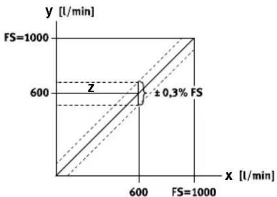
line
| FS [l/min] | x [l/min] | y [l/min] | | :--- | :--- | :--- | | 1000 | 600 | 600 | | 1000 | 600 | 600 | | 1000 | 1000 | 1000 | ±0.3% FSFig. 13 Zero point error
The error is specified at ± 0.3% FS according to specification. In our case, FS = 1000~l / min . The error is calculated as follows:
$$ \pm 0.3 \% \mathrm{FS} = \pm 0.3 / 100 \times 1000 \mathrm{l} / \mathrm{min} = \pm 3 \mathrm{l} / \mathrm{min} $$
Because of the zero point error, with a display of 600 l/min at the sensor, the actual flow rate through the sensor values can have values in the range 597 ... 603 l/min.
c) Total errors under nominal conditions
To the total errors under nominal conditions, the error margin of ±18.00 l/min and zero point of ±3.00 l/min must be added, so that at 600 l/min the following total error results:
$$ 6 0 0 \mathrm{l} / \mathrm{min} \pm 2 1. 0 0 \mathrm{l} / \mathrm{min} $$
With a display of 600 l/min at the sensor, because of the zero point error the actual flow rate through the sensor values can have values in the range of 579 ... 621 l/min.
d) Temperature fault
If the sensor is not operated at nominal conditions (6 bar, 0.6 MPa, 23 °C), e.g. at a pressure of 6 bar/0.6 MPa and a temperature of 40°C, which is outside nominal conditions with regard to temperature.
In this case, a temperature error must be added to the overall error worked out under nominal conditions.
According to specification:
- Temperature coefficients: typ. ±0.1 %FS/K.
As a deviation to the nominal condition, a temperature difference of 17^ at 40^ results. The temperature error range is calculated from the temperature difference and the temperature coefficient as follows:
$$ \pm 0.1 \% \mathrm{FS} / \mathrm{K} \times 17 \mathrm{K} = \pm 1.7 \% \mathrm{FS}. (\rightarrow \text {Fig.} 14) $$
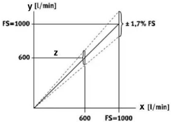
line
| FS | x [l/min] | y [l/min] | |--------|-----------|-----------| | 1000 | 600 | 600 | | 1000 | 1000 | 1000 |$$ x = \text { measured variable (flow rate) } $$
$$ y = \text { measurement value } (\text { display }) $$
$$ z = \text { display value error sought } $$
Fig. 14 Temperature fault
The maximum temperature error is calculated as follows:
$$ \pm 1.7 \% \mathrm{FS} = \pm 1.7 \% \times 1000 \mathrm{l} / \mathrm{min} = \pm 1.7 / 100 \times 1000 \mathrm{l} / \mathrm{min} = \pm 17.00 \mathrm{l} / \mathrm{min} $$
If a measured value of 600 l/min is displayed, the maximum temperature error range is thus calculated as follows:
$$ \pm 1 7 \mathrm{l} / \min \times (6 0 0 \mathrm{l} / \min) / (1 0 0 0 \mathrm{l} / \min) = \pm 1 0. 2 \mathrm{l} / \min $$
With a display of 600 l/min at the sensor and an ambient temperature of 40 °C, due to the temperature error range the actual flow rate through the sensor values can have values in the range 589.8 ... 610.2 l/min.
The total error of the sensor at 6 bar/0.6 MPa and 40 °C is calculated as follows:
Total error = (±precision error range) + (± precision error zero point) + (± temperature error range at 40 °C)
$$ = (\pm 1 8 \mathrm{l} / \min) + (\pm 3 \mathrm{l} / \min) + (\pm 1 0. 2 \mathrm{l} / \min) $$
$$ = \pm 3 1. 2 \mathrm{l} / \min $$
With a display of 600 l/min at the sensor and an ambient temperature of 40 C, the actual flow rate through the sensor can have values in the range 568.8 ... 631.2 l/min.
e) Error cause by pressure influence
If the sensor is also not operated in the pressure range at nominal conditions (6 bar, 23 °C), a pressure-dependent range must also be taken into account in determining the overall error. In determining the error as a result of the pressure dependency, the same approach should be used as when determining the temperature error.
SFAM
Copyright:
Festo SE & Co. KG
Ruiter Straße 82
73734 Esslingen
Germany
Phone:
+49 711 347-0
Fax:
+49 711 347-2144
Reproduction, distribution or sale of this document or communication of its contents to others without express authorization is prohibited. Offenders will be liable for damages. All rights reserved in the event that a patent, utility model or design patent is registered.
E-mail:
service_international@festo.com
Internet:
www.festo.com