DSL-G804V - Router D-LINK - Free user manual and instructions
Find the device manual for free DSL-G804V D-LINK in PDF.

User questions about DSL-G804V D-LINK
0 question about this device. Answer the ones you know or ask your own.
Ask a new question about this device
Download the instructions for your Router in PDF format for free! Find your manual DSL-G804V - D-LINK and take your electronic device back in hand. On this page are published all the documents necessary for the use of your device. DSL-G804V by D-LINK.
USER MANUAL DSL-G804V D-LINK
Wireless ADSL Router
User's Guide
TABLE OF CONTENTS
About This User's Guide ...... v
Before You Start....v
Installation Requirements ...... v
INTRODUCTION....1
Router Description and Operation.... 1
Front Panel Display....4
Rear Panel Connections 5
HARDWARE INSTALLATION 6
Power on Router....6
Factory Reset Button....6
Network Connections....7
Power On Router....8
Factory Reset Button....8
BASIC ROUTER CONFIGURATION....9
Configuring IP Settings on Your Computer....9
Access the Configuration Manager 15
Login to Home Page 15
Configure the Router.... 16
WAN....17
LAN Settings 26
Wireless Settings.... 29
DHCP Server 30
DNS Configuration 32
ADVANCED ROUTER MANAGEMENT ....33
Virtual Server....33
Add Virtual Server....34
Firewall 37
VPN 47
DDNS (Dynamic DNS) 60
Routing (Static Route) 61
Wireless....62
ADSL 65
IP QoS....66
Time Schedule 70
Check Email....72
Device Management 73
IGMP 75
TOOLS....76
Admin – Current Defined Users 76
System Date & Time....77
System Settings....78
Firmware Upgrade 79
Remote Access....79
Reboot 80
Save Config to FLASH....80
Logout....80
STATUS 82
Device Information 82
ARP 83
Routing Table....84
IPSec Status 85
PPTP Status....86
L2TP Status 86
DHCP Status 87
Email Status 89
Event Log 89
Error Log....90
NAT Sessions....90
UPnP Portmap....91
Help....91
TECHNICAL SPECIFICATIONS....92
IP ADDRESS SETUP....94
IP CONCEPTS....96
MICROFILTERS AND SPLITTERS 99
About This User's Guide
This user's guide provides instructions on how to install the DSL-G804V Wireless ADSL Router and use it to connect a computer or Ethernet LAN to the Internet.
If you are using a computer with a functioning Ethernet port, the quickest and easiest way to set up the DSL-G804V is to insert the Installation CD into the CD-ROM drive of your computer and follow the instructions provided in the Quick Installation Guide.
Before You Start
Please read and make sure you understand all the prerequisites for proper installation of your new Router. Have all the necessary information and equipment on hand before beginning the installation.
Installation Overview
The procedure to install the Router can be described in general terms in the following steps:
- Gather information and equipment needed to install the device. Before you begin the actual installation make sure you have all the necessary information and equipment.
- Install the hardware, that is, connect the cables (Ethernet and telephone) to the device and connect the power adapter.
- Check the IP settings on your computer and change them if necessary so the computer can access the web-based software built into the Router.
- Use the web-based management software to configure the device to suit the requirements of your ADSL account.
Installation Requirements
In order to establish a connection to the Internet it will be necessary to provide information to the Router that will be stored in its memory. For some users, only their account information (Username and Password) is required. For others, various parameters that control and define the Internet connection will be required. You can print out the two pages below and use the tables to list this information. This way you have a hard copy of all the information needed to setup the Router. If it is necessary to reconfigure the device, all the necessary information can be easily accessed. Be sure to keep this information safe and private.
Low Pass Filters
Since ADSL and telephone services share the same copper wiring to carry their respective signals, a filtering mechanism may be necessary to avoid mutual interference. A low pass filter device can be installed for each telephone that shares the line with the ADSL line. These filters are easy to install passive devices that connect to the ADSL device and/or telephone using standard telephone cable. Ask your service provider for more information about the use of low pass filters with your installation.
Operating Systems
The DSL-G804V uses an HTML-based web interface for setup and management. The web configuration manager may be accessed using any operating system capable of running web browser software, including Windows 98, Windows NT, Windows 2000, Windows XP and Me.
Web Browser
Any common web browser can be used to configure the Router using the web configuration management software. The program is designed to work best with more recently released browsers such as Opera, Microsoft Internet Explorer® version 5.0, Netscape Navigator® version 4.5, or later versions. The web browser must have JavaScript enabled. JavaScript is enabled by default on many browsers. Make sure JavaScript has not been disabled by other software (such as virus protection or web user security packages) that may be running on your computer.
Ethernet Port (NIC Adapter)
Any computer that uses the Router must be able to connect to it through the Ethernet port on the Router. This connection is an Ethernet connection and therefore requires that your computer be equipped with an Ethernet port as well. Most notebook computers are now sold with an Ethernet port already installed. Likewise, most fully assembled desktop computers come with an Ethernet NIC adapter as standard equipment. If your computer does not have an Ethernet port, you must install an Ethernet NIC adapter before you can use the Router. If you must install an adapter, follow the installation instructions that come with the Ethernet NIC adapter.
Additional Software
It may be necessary to install software on your computer that enables the computer to access the Internet. Additional software must be installed if you are using the device a simple bridge. For a bridged connection, the information needed to make and maintain the Internet connection is stored on another computer or gateway device, not in the Router itself.
If your ADSL service is delivered through a PPPoE, PPPoA or CLIP (IPoA) connection, the information needed to establish and maintain the Internet connection can be stored in the Router. In this case, it is not necessary to install software on your computer. It may however be necessary to change some settings in the device, including account information used to identify and verify the connection.
All connections to the Internet require a unique global IP address. For bridged connections, the global IP settings must reside in a TCP/IP enabled device on the LAN side of the bridge, such as a PC, a server, a gateway device such as a router or similar firewall hardware. The IP address can be assigned in a number of ways. Your network service provider will give you instructions about any additional connection software or NIC configuration that may be required.
About CLIP Connections (RFC 1577)
Classical IP over ATM (CLIP) connections may require global IP settings for the device. Your service provider will give you IP settings information if needed. Some CLIP connections function like peer-to-peer connections and therefore do not require IP settings on the WAN interface.
Information you will need from your ADSL service provider:
| Username | This is the Username used to log on to your ADSL service provider's network. It is commonly in the form - user@isp.com. Your ADSL service provider uses this to identify your account. | Record info here |
| Password | This is the Password used, in conjunction with the Username above, to log on to your ADSL service provider's network. This is used to verify the identity of your account. | |
| Connection Protocol | This is the method your ADSL service provider uses to send and receive data between the Internet and your computer. Your Modem supports the following connection protocols: PPPoE, PPPoA, PPPoA with DHCP, Bridge, and CLIP (IPoA). | |
| Modulation Type | ADSL uses various standardized modulation techniques to transmit data over the allotted signal frequencies. Some users may need to change the type of modulation used for their service. The default DSL modulation (MMODE) used for the Router automatically detects all types of ADSL modulation. However, if you are instructed to specify the modulation type used for the Router, you have three alternatives: G.LITE, G.DMT and T1.413 | |
| Security Protocol | This is the method your ADSL service provider will use to verify your Username and Password when you log on to their network. Your Modem supports the PAP and CHAP protocols. | |
| VPI | This is the Virtual Path Identifier (VPI). It is used in conjunction with the Virtual Channel Identifier (VCI) below, to identify the data path between your ADSL service provider's network and your computer. | |
| VCI | This is the Virtual Channel Identifier (VCI). It is used in conjunction with the VPI above to identify the data path between your ADSL service provider's network and your computer. |
Information you will need about your DSL-G804V Wireless ADSL Router:
| Username | This is the Username needed access the Modem's management interface. When you attempt to connect to the device through a web browser you will be prompted to enter this Username. The default Username for the Modem is admin. This may be changed by the user. | Record info here |
| Password | This is the Password you will be prompted to enter when you access the Modem's management interface. The default Password is admin. This may be changed by the user. | |
| LAN IP addresses for the DSL-G804V | This is the IP address you will enter into the Address field of your web browser to access the Modem's configuration graphical user interface (GUI) using a web browser. The default IP address is 192.168.1.1 and it is referred to as the “Management IP” address in this User's Manual. This may be changed to suit any IP address scheme the user desires. This address will be the base IP address used for DHCP service on the LAN when DHCP is enabled. | |
| LAN Subnet Mask for the DSL-G804V | This is the subnet mask used by the DSL-G804V, and will be used throughout your LAN. The default subnet mask is 255.255.255.0. This can be changed later. |
Information you will need about your LAN or computer:
| Ethernet NIC | If your computer has an Ethernet NIC, you can connect the DSL-G804V to this Ethernet port using an Ethernet cable. You can also use the Ethernet port on the DSL-G804V to connect to other Ethernet devices, such as a Wireless Access Point. | Record info here |
| DHCP Client status | Your DSL-G804V ADSL Modem is configured, by default, to be a DHCP server. This means that it can assign an IP address, subnet mask, and a default gateway address to computers on your LAN. The default range of IP addresses the DSL-G804V will assign are from 192.168.1.2 to 192.168.1.254. Your computer (or computers) needs to be configured to Obtain an IP address automatically (that is, they need to be configured as DHCP clients.) |
It is recommended that your collect and record this information here, or in some other secure place, in case you have to re-configure your ADSL connection in the future.
Once you have the above information, you are ready to setup and configure your DSL-G804V ADSL Router.

The Modem may be reset to its factory default settings by performing a Restore settings operation within the management interface. If you cannot gain access to the management interface, you may opt to use the Reset button on the rear panel of the device).

Introduction
This section provides a brief description of the Router, its associated technologies and a list of Router features.
Router Description and Operation
The DSL-G804V Wireless ADSL Router is designed to provide a simple and cost-effective ADSL Internet connection for individual computers through the Ethernet ports, or use it to bridge your Ethernet LAN to the Internet. The DSL-G804V combines the benefits of high-speed ADSL technology and LAN IP management in one compact and convenient package. ADSL technology enables many interactive multi-media applications such as video conferencing and collaborative computing.
The Router is easy to install and use. The DSL-G804V connects to computers or an Ethernet LAN via a standard Ethernet interface. The ADSL connection is made using ordinary twisted-pair telephone line with standard connectors. Multiple PCs can be networked and connected to the Internet using a single Wide Area Network (WAN) interface and single global IP address.
It supports the latest ADSL2/2+ technology enabling high-speed data rates of up to 24Mbps, Its powerful QoS feature for traffic priority and bandwidth management, and security features including multiple VPN tunnels with 3DES make the device a perfect mate to the office user or for anyone who has the compelling needs to transmit sensitive data more securely. With integrated 54Mbps 802.11g Access Point in this device, the router brings up the productivity and mobility to office users.
The Router supports transparent bridging and can be used for IP packet routing over the Internet. Cost saving features of the Router such as NAT (Network Address Translator) and DHCP (Dynamic Host Configuration Protocol) improve administration efficiency and improve security for your private network.
What is ADSL?
Asymmetric Digital Subscriber Line (ADSL) is an access technology that utilizes ordinary copper telephone lines to enable broadband high-speed digital data transmission and interactive multimedia applications for business and residential customers.
ADSL greatly increases the signal carrying capacity of copper telephone lines without interfering with regular telephone services. For the ADSL user, this means faster downloads and more reliable connectivity. ADSL devices make it possible to enjoy benefits such as high-speed Internet access without experiencing any loss of quality or disruption of voice/fax telephone capabilities.
ADSL provides a dedicated service over a single telephone line operating at speeds of up to 8 Mbps downstream and up to 640 Kbps upstream, depending on local telephone line conditions. A secure point-to-point connection is established between the user and the central office of the service provider.
D-Link ADSL devices incorporate the recommendations of the ADSL Forum regarding framing, data format, and upper layer protocols.
Router Features
The DSL-G804V ADSL Router utilizes the latest ADSL enhancements to provide a reliable Internet portal suitable for most small to medium sized offices. DSL-G804V advantages include:
- Express Internet Access – capable of ADSL2/2+ –The router complies with ADSL worldwide standards. It supports downstream rates up to 8Mbps with ADSL, capable of up to 12/24 Mbps with ADSL2/2+, and upstream rates up to 1 Mbps. Users enjoy not only high-speed ADSL services but also broadband multimedia applications such as interactive gaming, video streaming and real-time audio much easier and faster than ever. It is compliant with Multi-Mode standard (ANSI T1.413, Issue 2; G.dmt (ITU G.992.1); G.hs (ITU G994.1); G.dmt.bis (ITU G.992.3); G.dmt.bisplus (ITU G.992.5)).
- Wireless Ethernet 802.11g – With integrated 802.11g Wireless Access Point in the router, the device offers a quick and easy access among wired network, wireless network and broadband connection (ADSL) with single device simplicity, and as a result, mobility to the users. In addition to 54 Mbps 802.11g data rate, it also interoperates backward with existing 802.11b equipment. The Wireless Protected Access (WPA) and Wireless Encryption Protocol (WEP) supported features enhance the security level of data protection and access control via Wireless LAN.
- Fast Ethernet Switch – A 4-port 10/100Mbps fast Ethernet switch is built in with automatic switching between MDI and MDI-X for 10Base-T and 100Base-TX ports. An Ethernet straight or crossover cable can be used directly for auto detection.
- Multi-Protocol to Establish A Connection – Supports PPPoA (RFC 2364 - PPP over ATM Adaptation Layer 5), RFC 1483 encapsulation over ATM (bridged or routed), PPP over Ethernet (RFC 2516) and IPoA (RFC1577) to establish a connection with the ISP. The product also supports VC-based and LLC-based multiplexing.
- Quick Installation Wizard – Supports a WEB GUI page to install this device quickly. With this wizard, end users can enter the information easily which they get from their ISP, then surf the Internet immediately.
- Universal Plug and Play (UPnP) and UPnP NAT Traversal –This protocol is used to enable simple and robust connectivity among stand-alone devices and PCs from many different vendors. It makes network simple and affordable for users. UPnP architecture leverages TCP/IP and the Web to enable seamless proximity networking in addition to control and data transfer among networked devices. With this feature enabled, users can now connect to Net meeting or MSN Messenger seamlessly.
- Network Address Translation (NAT) – Allows multi-users to access outside resources such as the Internet simultaneously with one IP address/one Internet access account. Many application layer gateway (ALG) are supported such as web browser, ICQ, FTP, Telnet, E-mail, News, Net2phone, Ping, NetMeeting, IP phone and others.
- Firewall – Supports SOHO firewall with NAT technology. Automatically detects and blocks Denial of Service (DoS) attacks. The URL blocking, packet filtering and SPI (Stateful Packet Inspection) are also supported. The hacker's attack will be recorded associated with timestamp in the security logging area. More firewall functions will always be implemented through updated firmware releases.
- Domain Name System (DNS) relay – Provides an easy way to map the domain name (a friendly name for users such as www.yahoo.com) and IP address. When local machine sets its DNS server with this router's IP address, every DNS conversion request packet from the PC to this router will be forwarded to the real DNS in the outside network.
- Dynamic Domain Name System (DDNS) – The Dynamic DNS service allows you to alias a dynamic IP address to a static hostname. This dynamic IP address is the WAN IP address. For example, to use the service, you must first apply for an account from a DDNS service like http://www.dyndns.org/. More than 5 DDNS servers are supported.
-
PPP over Ethernet (PPPoE) – Provides embedded PPPoE client function to establish a connection. Users can get greater access speed without changing the operation concept, sharing the same ISP account and paying for one access account. No PPPoE client software is required for local computer. The Automatic Reconnect and Disconnect Timeout (Idle Timer) functions are provided, too.
-
Virtual Private Network (VPN) – Allows user to make a tunnel with a remote site directly to secure the data transmission among the connection. User can use embedded PPTP and L2TP client/server, IKE and IPSec which are supported by this router to make a VPN connection or users can run the PPTP client in PC and the router already provides IPSec and PPTP pass through function to establish a VPN connection if the user likes to run the PPTP client in his local computer.
- Virtual Server (“port forwarding”) – Users can specify some services to be visible from outside users. The router can detect incoming service requests and forward either a single port or a range of ports to the specific local computer to handle it. For example, a user can assign a PC in the LAN acting as a WEB server inside and expose it to the outside network. Outside users can browse inside web servers directly while it is protected by NAT. A DMZ host setting is also provided to a local computer exposed to the outside network, Internet.
- Rich Packet Filtering – Not only filters the packet based on IP address, but also based on Port numbers. It will filter packets from and to the Internet, and also provides a higher level of security control.
- Dynamic Host Configuration Protocol (DHCP) client and server – In the WAN site, the DHCP client can get an IP address from the Internet Service Provider (ISP) automatically. In the LAN site, the DHCP server can allocate a range of client IP addresses and distribute them including IP address, subnet mask as well as DNS IP address to local computers. It provides an easy way to manage the local IP network.
- Static and RIP1/2 Routing – Supports an easy static routing table or RIP1/2 routing protocol to support routing capability.
- Simple Network Management Protocol (SNMP) – It is an easy way to remotely manage the router via SNMP.
- Web based GUI – Supports web based GUI for configuration and management. It is user-friendly and comes with on-line help. It also supports remote management capability for remote users to configure and manage this product.
- Firmware Upgradeable – Device can be upgraded to the latest firmware through the WEB based GUI.
- Rich management interfaces – Supports flexible management interfaces with local console port, LAN port, and WAN port. Users can use terminal applications through the console port to configure and manage the device, or Telnet, WEB GUI, and SNMP through LAN or WAN ports to configure and manage the device.
Packing List
Open the shipping carton and carefully remove all items. In addition to this User's Guide, ascertain that you have:
• One DSL-G804V ADSL Router
• One twisted-pair telephone cable used for ADSL connection
• One straight-through Ethernet cable
• One Console (PS2-RS232) Cable
• One DC power adapter suitable for your electric service
- An Installation CD-ROM containing this User's Guide
Front Panel Display
Place the Router in a location that permits an easy view of the LED indicators on the front panel.
The LED indicators on the front panel include the Power, Status, ADSL Link/Act, WLAN, LAN (1-4) Link/Act and PPP/Mail indicators. The ADSL and Ethernet indicators monitor link status and activity (Link/Act).

text_image
D-Link DEL VPN Renter 120V 4 2 3 4 5 6 DSL-0804V| Power | Steady green light indicates the unit is powered on. When the device is powered off this remains dark. |
| Status | Lights steady green during power on self-test (POST). Once the connection status has been settled, the light will blink green. If the indicator lights steady green after the POST, the system has failed and the device should be rebooted. |
| ADSL: Link/Act | Steady green light indicates a valid ADSL connection. This will light after the ADSL negotiation process has been settled. A blinking green light indicates activity on the WAN (ADSL) interface. |
| WLAN | Lit green when the wireless connection is established. A blinking green when sending/receiving data. |
| LAN 1 - 4: Link/Act | Green: The router has a successful 100Mb Ethernet connection. A solid green light indicates a valid link on startup. These lights blink when there is activity currently passing through the Ethernet port.Orange: The router has a successful 10Mb Ethernet connection. A solid green light indicates a valid link on startup. These lights blink when there is activity currently passing through the Ethernet port. |
| PPP / MAIL | Lit steady when there is a PPPoA / PPPoE connection. Lit and flashed periodically when there is email in the Inbox |
Rear Panel Connections
All cable connections to the Router are made at the rear panel. Connect the power adapter here to power on the Router. Use the Reset button to restore the settings to the factory default values.
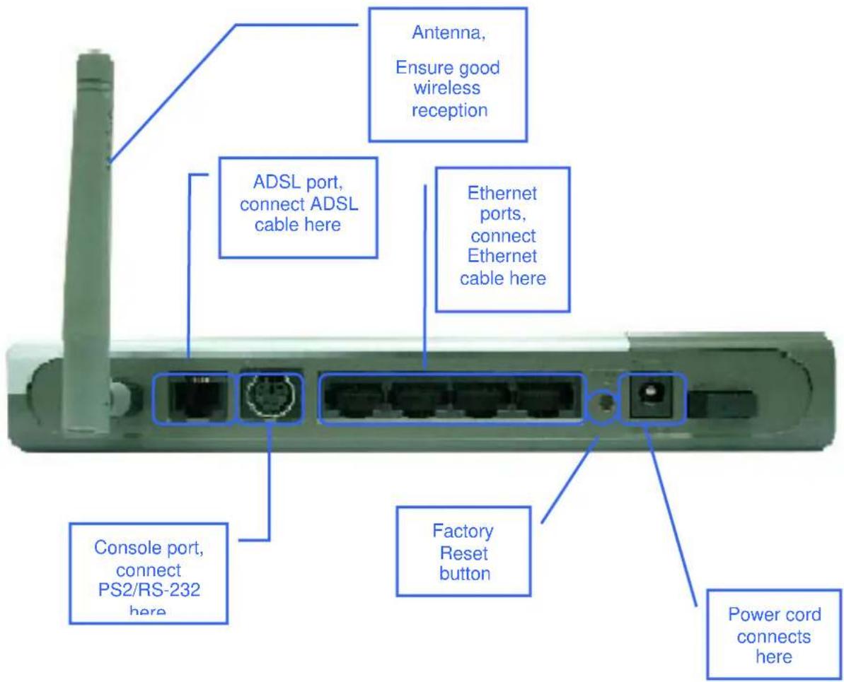
text_image
Antenna, Ensure good wireless reception ADSL port, connect ADSL cable here Ethernet ports, connect Ethernet cable here Console port, connect PS2/RS-232 here Factory Reset button Power cord connects here
Hardware Installation
The DSL-G804V maintains five separate interfaces, four Ethernet and one ADSL interface. Place the Router in a location where it can be safely connected to the various devices as well as to a power source. The Router should not be located where it will be exposed to moisture or excessive heat. Make sure the cables and power cord are placed safely out of the way so they do not create a tripping hazard. As with any electrical appliance, observe common sense safety precautions.
The access point can be placed on a shelf or desktop, ideally you should be able to see the LED indicators on the front if you need to view them for troubleshooting.
Power on Router

CAUTION: The Router must be used with the power adapter included with the device.
To power on the Router:
- Insert the DC Power Adapter cord into the power receptacle located on the rear panel of the Router and plug the adapter into a suitable nearby power source.
- You should see the Power LED indicator light up and remain lit. The Status LED should light solid green and begin to blink after a few seconds.
- If the Ethernet port is connected to a working device, check the Ethernet Link/Act LED indicators to make sure the connection is valid. The Router will attempt to establish the ADSL connection, if the ADSL line is connected and the Router is properly configured this should light up after several seconds. If this is the first time installing the device, some settings may need to be changed before the Router can establish a connection.
Factory Reset Button
The Router may be reset to the original factory default settings by depressing the reset button for a few seconds while the device is powered on. Use a ballpoint or paperclip to gently push down the reset button. Remember that this will wipe out any settings stored in flash memory including user account information and LAN IP settings. The factory default IP address of the Router is 192.168.1.1 and the subnet mask is 255.255.255.0, the default management Username is admin and the default Password is admin.
Network Connections
Network connections are provided through the ADSL port and the four Ethernet ports on the back of the Router. See the Rear Panel diagram above and the illustrations below for examples.
Connect ADSL Line
Use the ADSL cable included with the Router to connect it to a telephone wall socket or receptacle. Plug one end of the cable into the ADSL port (RJ-11 receptacle) on the rear panel of the Router and insert the other end into the RJ-11 wall socket. If you are using a low pass filter device, follow the instructions included with the device or given to you by your service provider. The ADSL connection represents the WAN interface, the connection to the Internet. It is the physical link to the service provider's network backbone and ultimately to the Internet.
Connect Router to Ethernet
The Router may be connected to a single computer or Ethernet device through the 10BASE-TX Ethernet port on the rear panel. Any connection to an Ethernet concentrating device such as a switch or hub must operate at a speed of 10/100 Mbps only. When connecting the Router to any Ethernet device that is capable of operating at speeds higher than 10Mbps, be sure that the device has auto-negotiation (NWay) enabled for the connecting port.
Use standard twisted-pair cable with RJ-45 connectors. The RJ-45 port on the Router is a crossed port (MDI-X). Follow standard Ethernet guidelines when deciding what type of cable to use to make this connection. When connecting the Router directly to a PC or server use a normal straight-through cable. You should use a crossed cable when connecting the Router to a normal (MDI-X) port on a switch or hub. Use a normal straight-through cable when connecting it to an uplink (MDI-II) port on a hub or switch.
The rules governing Ethernet cable lengths apply to the LAN to Router connection. Be sure that the cable connecting the LAN to the Router does not exceed 100 meters.
Hub or Switch to Router Connection
Connect the Router to an uplink port (MDI-II) on an Ethernet hub or switch with a straight-through cable as shown in the diagram below:

text_image
10M Switch/Hub 10/100 BASE-TX Cable (straight-through wires) 10/100 BASE-TX (straight-through)If you wish to reserve the uplink port on the switch or hub for another device, connect to any on the other MDI-X ports (1x, 2x, etc.) with a crossed cable.
Computer to Router Connection
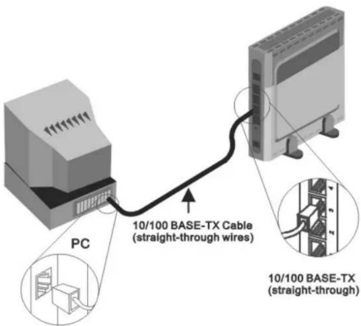
text_image
PC 10/100 BASE-TX Cable (straight-through wires) 10/100 BASE-TX (straight-through)You can connect the Router directly to a 10/100BASE-TX Ethernet adapter card (NIC) installed on a PC using the Ethernet cable provided as shown in this diagram.
Power On Router
To power on the Router:
- Insert the DC Power Adapter cord into the power receptacle located on the rear panel of the Router and plug the adapter into a suitable nearby power source.
- You should see the Power LED indicator light up and remain lit. The Status LED should light solid green and begin to blink after a few seconds.
- If you have the Router connected to your network you can look at the Ethernet Link/Act LED indicators to make sure they have valid connections. The Router will attempt to establish the ADSL connection, if the ADSL line is connected and the connection is properly configured this should light up after several seconds.
Factory Reset Button
The Router may be reset to the original factory default settings by depressing the reset button for a few seconds while the device is powered on. Use a ballpoint or paperclip to push down the reset button. Remember that this will wipe out any settings stored in flash memory including IP settings. The factory default IP address of the Router is 192.168.1.1 and the subnet mask is 255.255.255.0.

Basic Router Configuration
The first time you setup the Router it is recommended that you configure the WAN connection using a single computer making sure that both the computer and the Router are not connected to the LAN. Once the WAN connection is functioning properly, you may continue to make changes to Router configuration including IP settings and DHCP setup. This chapter is concerned with using your computer to configure the WAN connection. The following chapter describes the various menus used to configure and monitor the Router including how to change IP settings and DHCP server setup.
Wan Configuration Summary
-
Connect to the Router To configure the WAN connection used by the Router it is first necessary to communicate with the Router through its management interface, which is HTML-based and can be accessed using a web browser. To access the management software your computer must be able to "see" the Router. Your computer can see the Router if it is in the same "neighborhood" or subnet as the Router. This is accomplished by making sure your computer has IP settings that place it in the same subnet as the Router. The easiest way to make sure your computer has the correct IP settings is to configure it to use the DHCP server in the Router. The next section describes how to change the IP configuration for a computer running a Windows operating system to be a DHCP client.
-
Configure the WAN Connection Once your are able to access the configuration software you can proceed to change the settings required to establish the ADSL connection and connect to the service provider's network. There are different methods used to establish the connection to the service provider's network and ultimately to the Internet. You should know what Encapsulation and connection type you are required to use for your ADSL service. It is also possible that you must change the PVC settings used for the ADSL connection. Your service provider should provide all the information you need to configure the WAN connection.
Configuring IP Settings on Your Computer
In order to configure your system to receive IP settings from the Router it must first have the TCP/IP protocol installed. If you have an Ethernet port on your computer, it probably already has TCP/IP protocol installed. If you are using Windows XP the TCP/IP is enabled by default for standard installations. Below is an illustrated example of how to configure a Windows XP system to automatically obtain IP settings from the Router. Following this example is a step-by-step description of the procedures used on the other Windows operating systems to first check if the TCP/IP protocol has been installed; if it is not, instructions are provided for installing it. Once the protocol has been installed you can configure the system to receive IP settings from the Router.
For computers running non-Windows operating systems, follow the instructions for your OS that configure the system to receive an IP address from the Router, that is, configure the system to be a DHCP client.

If you are using this Router to provide Internet access for more than one computer, you can use these instructions later to change the IP settings for the other computers. However, you cannot use the same IP address since every computer must have its own IP address that is unique on the local network.
Configure Windows XP for DHCP
Use the following steps to configure a computer running Windows XP to be a DHCP client.
- From the Start menu on your desktop, go to Settings, then click on Network Connections.
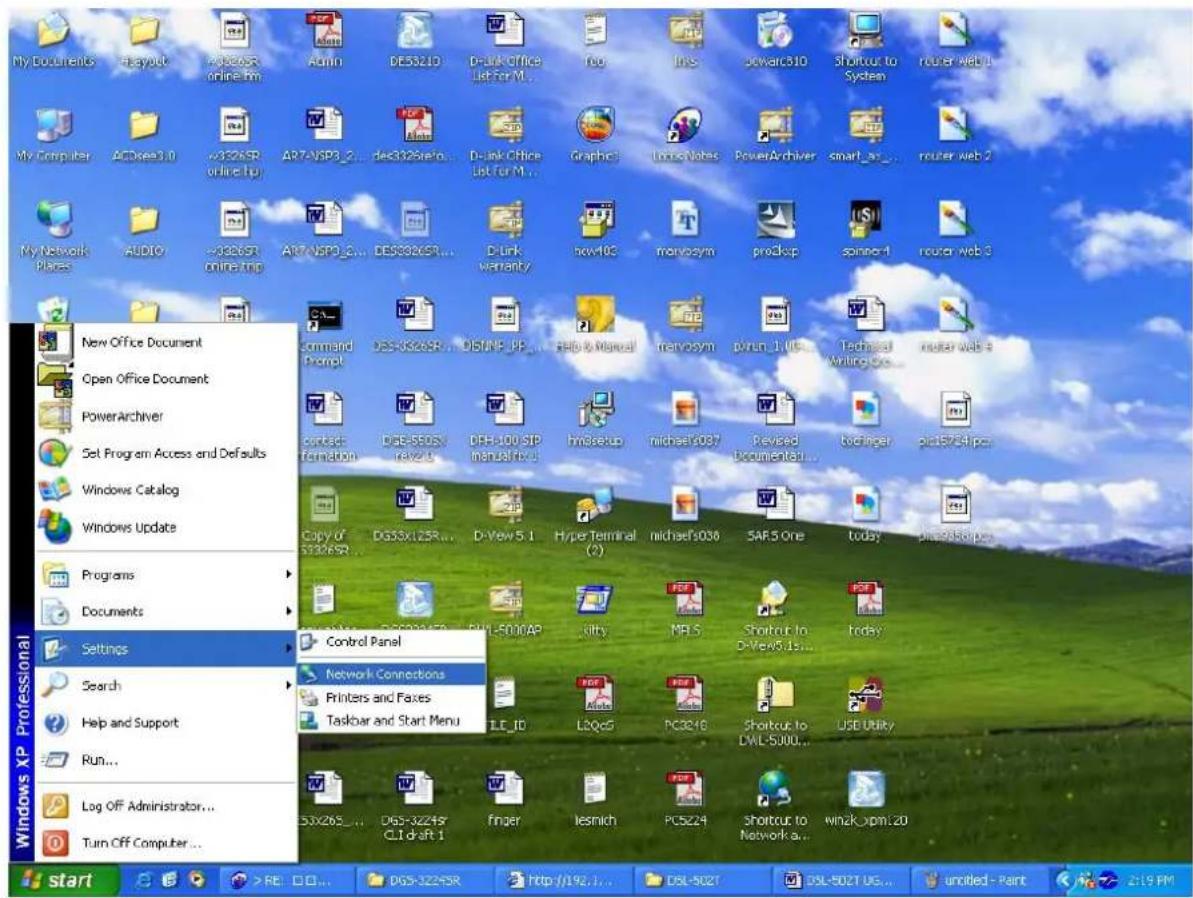
text_image
My Documents My Computer My Network New Office Document Open Office Document PowerArchiver Set Program Access and Defaults Windows Catalog Windows Update Programs Documents Settings Search Help and Support Run... Log Off Administrator... Turn Off Computer... Windows XP Professional Start > RE > DGS-3224SR DGS-3224SR online.htm Admin DES321D D-link Office List for M... Web Links Docwarc310 Shortcut to System router web 1 AR7-NSP3_2... dec312SInfo... D-link Office List for M... Graphc1 Online Notes PowerArchiver smart as... router web 2 AR7-NSP3_2... DES3224SR... Dlink warranty new103 menvosym procksp spinner-1 router web 3 Command Prompt DES-3224SR... DBMP-PP... File & Manual menvosym pvrun_1 Web Technical Writing Box router web 8 contact formation DSE-5E0SX Review DFE-100 SIP manual Web hmSetup michael's037 Revised documentar ... boeringer pin15764ipen Copy of SSSR... DG53x125R... D-View 5.1 Hyper Terminal (2) michael's036 SAR5 One today printer/boxp Control Panel Network Connections Printers and Fases Taskbar and Start Menu TLE_ID L2QcG PC321B Shortcut to DML-S000... USB Utility DSX26S... DGS-3224SR CLI draft 1 finger lesmich PCS224 Shortcut to Network a... winzk_xpm.20- In the Network Connections window, right-click on LAN (Local Area Connection), then click Properties.
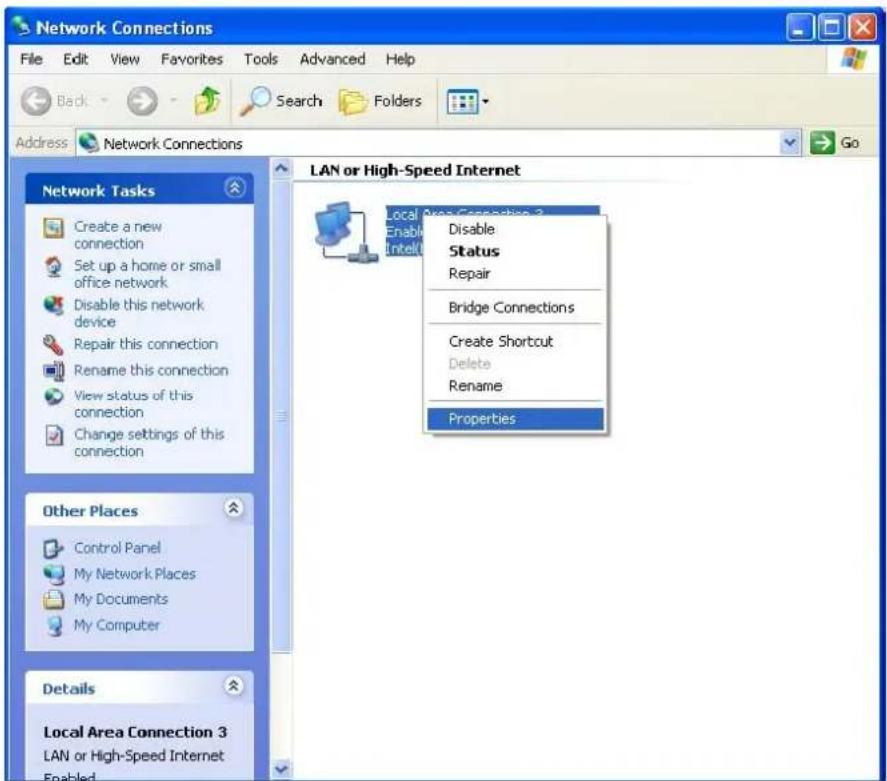
text_image
Network Connections File Edit View Favorites Tools Advanced Help Back Search Folders Address Network Connections Network Tasks Create a new connection Set up a home or small office network Disable this network device Repair this connection Rename this connection View status of this connection Change settings of this connection LAN or High-Speed Internet Local Area Connection 3 Enable Intel Disable Status Repair Bridge Connections Create Shortcut Delete Rename Properties Other Places Control Panel My Network Places My Documents My Computer Details Local Area Connection 3 LAN or High-Speed Internet Enabled- In the General tab of the Local Area Connection Properties menu, highlight Internet Protocol (TCP/IP) under "This connection uses the following items:" by clicking on it once. Click on the Properties button.

text_image
Local Area Connection 3 Properties General Authentication Advanced Connect using: Intel(R) PRO/100 VE Network Connection Configure... This connection uses the following items: ✓ Client for Microsoft Networks ✓ File and Printer Sharing for Microsoft Networks ✓ QoS Packet Scheduler ✓ Internet Protocol (TCP/IP) Install... Uninstall Properties Description Transmission Control Protocol/Internet Protocol. The default wide area network protocol that provides communication across diverse interconnected networks. Show icon in notification area when connected OK Cancel- Select "Obtain an IP address automatically" by clicking once in the circle. Click the OK button.

text_image
Internet Protocol (TCP/IP) Properties General Alternate Configuration You can get IP settings assigned automatically if your network supports this capability. Otherwise, you need to ask your network administrator for the appropriate IP settings. Obtain an IP address automatically Use the following IP address: IP address: Subnet mask: Default gateway: Obtain DNS server address automatically Use the following DNS server addresses: Preferred DNS server: 172 . 19 . 10 . 40 Alternate DNS server: 172 . 19 . 10 . 35 Advanced... OK CancelYour computer is now ready to use the Router's DHCP server.
Windows 2000
First, check for the IP protocol and, if necessary, install it:
- In the Windows task bar, click the Start button, point to Settings, and then click Control Panel.
- Double-click the Network and Dial-up Connections icon.
- In the Network and Dial-up Connections window, right-click the Local Area Connection icon, and then select Properties.
- The Local Area Connection Properties dialog box displays with a list of currently installed network components. If the list includes Internet Protocol (TCP/IP), then the protocol has already been enabled, skip ahead to Configure Windows 2000 for DHCP.
- If Internet Protocol (TCP/IP) does not display as an installed component, click Install.
- In the Select Network Component Type dialog box, select Protocol, and then click Add.
- Select Internet Protocol (TCP/IP) in the Network Protocols list, and then click OK.
- You may be prompted to install files from your Windows 2000 installation CD or other media. Follow the instructions to install the files.
- If prompted, click OK to restart your computer with the new settings.
Configure Windows 2000 for DHCP
- In the Control Panel, double-click the Network and Dial-up Connections icon.
- In Network and Dial-up Connections window, right-click the Local Area Connection icon, and then select Properties.
- In the Local Area Connection Properties dialog box, select Internet Protocol (TCP/IP), and then click Properties.
- In the Internet Protocol (TCP/IP) Properties dialog box, click the button labeled Obtain an IP address automatically.
- Double-click OK to confirm and save your changes, and then close the Control Panel.
Your computer is now ready to use the Router's DHCP server.
Windows ME
First, check for the IP protocol and, if necessary, install it:
- In the Windows task bar, click the Start button, point to Settings, and then click Control Panel.
- Double-click the Network and Dial-up Connections icon.
- In the Network and Dial-up Connections window, right-click the Network icon, and then select Properties.
- The Network Properties dialog box displays with a list of currently installed network components. If the list includes Internet Protocol (TCP/IP), then the protocol has already been enabled. Skip ahead to Configure Windows ME for DHCP.
- If Internet Protocol (TCP/IP) does not display as an installed component, click Add.
- In the Select Network Component Type dialog box, select Protocol, and then click Add.
- Select Microsoft in the Manufacturers box.
- Select Internet Protocol (TCP/IP) in the Network Protocols list, and then click OK.
- You may be prompted to install files from your Windows Me installation CD or other media. Follow the instructions to install the files.
- If prompted, click OK to restart your computer with the new settings.
Configure Windows ME for DHCP
- In the Control Panel, double-click the Network and Dial-up Connections icon.
- In the Network and Dial-up Connections window, right-click the Network icon, and then select Properties.
- In the Network Properties dialog box, select TCP/IP, and then click Properties.
- In the TCP/IP Settings dialog box, click the Obtain and IP address automatically option.
- Double-click OK twice to confirm and save your changes, and then close the Control Panel.
Your computer is now ready to use the Router's DHCP server.
Windows 95 and Windows 98
First, check for the IP protocol and, if necessary, install it:
- In the Windows task bar, click the Start button, point to Settings, and then click Control Panel. Double-click the Network icon.
- The Network dialog box displays with a list of currently installed network components. If the list includes TCP/IP, and then the protocol has already been enabled, skip to Configure IP Information Windows 95, 98.
- If TCP/IP does not display as an installed component, click Add. The Select Network Component Type dialog box displays.
- Select Protocol, and then click Add. The Select Network Protocol dialog box displays.
- Click on Microsoft in the Manufacturers list box, and then click TCP/IP in the Network Protocols list box.
- Click OK to return to the Network dialog box, and then click OK again. You may be prompted to install files from your Windows 95/98 installation CD. Follow the instructions to install the files.
- Click OK to restart the PC and complete the TCP/IP installation.
Configure Windows 95 and Windows 98 for DHCP
- Open the Control Panel window, and then click the Network icon.
- Select the network component labeled TCP/IP, and then click Properties.
- If you have multiple TCP/IP listings, select the listing associated with your network card or adapter.
- In the TCP/IP Properties dialog box, click the IP Address tab.
- Click the Obtain an IP address automatically option.
- Double-click OK to confirm and save your changes. You will be prompted to restart Windows.
- Click Yes.
When it has restarted your computer is ready to use the Router's DHCP server.
Windows NT 4.0 Workstations
First, check for the IP protocol and, if necessary, install it:
- In the Windows NT task bar, click the Start button, point to Settings, and then click Control Panel.
- In the Control Panel window, double-click the Network icon.
- In the Network dialog box, click the Protocols tab.
- The Protocols tab displays a list of currently installed network protocols. If the list includes TCP/IP, then the protocol has already been enabled. Skip to “Configure IP Information”
- If TCP/IP does not display as an installed component, click Add.
- In the Select Network Protocol dialog box, select TCP/IP, and then click OK. You may be prompted to install files from your Windows NT installation CD or other media. Follow the instructions to install the files.
- After all files are installed, a window displays to inform you that a TCP/IP service called DHCP can be set up to dynamically assign IP information.
- Click Yes to continue, and then click OK if prompted to restart your computer.
Configure Windows NT 4.0 for DHCP
- Open the Control Panel window, and then double-click the Network icon.
- In the Network dialog box, click the Protocols tab.
- In the Protocols tab, select TCP/IP, and then click Properties.
- In the Microsoft TCP/IP Properties dialog box, click the Obtain an IP address automatically option.
- Click OK twice to confirm and save your changes, and then close the Control Panel.
Access the Configuration Manager
Now that your computer's IP settings allow it to communicate with the Router, you can access the configuration software.

Be sure that the web browser on your computer is not configured to use a proxy server in the Internet settings. In Windows Internet Explorer, you can check if a proxy server is enabled using the following procedure:
- In Windows, click on the Start button, go to Settings and choose Control Panel.
- In the Control Panel window, double-click on the Internet Options icon.
- Click the Connections tab and click on the LAN Settings button.
- Verify that the "Use proxy server" option is NOT checked. If it is checked, click in the checked box to deselect the option and click OK.
Alternatively, you can access this Internet Options menu using the Tools pull-down menu in Internet Explorer.
To use the web-based management software, launch a suitable web browser and direct it to the IP address of the Router. Type in http:// followed by the default IP address, 192.168.1.1 in the address bar of the browser. The URL in the address bar should read: http://192.168.1.1.
Login to Home Page
A new window will appear and you will be prompted for a user name and password to access the web-based manager.

text_image
Enter Network Password Please type your user name and password. Site: 192.168.1.1 Realm WebAdmin User Name Password Save this password in your password list OK CancelFigure 3-1. Home - Login window
Use the default user name admin and password admin for first time setup. You should change the web-based manager access user name and password once you have verified that a connection can be established. The user name and password allows any PC within the same subnet as the Modem to access the web-based manger.

Do not confuse the user name and password used to access the web-based manager with the ADSL account user name and password needed for PPP connections to access the service provider's network.
Configure the Router
The first page that appears after you successfully login displays information about the Router and its connection status. Tabs across the top of the screen show other available menus: Setup, Advanced, Tools, Status, and Help.
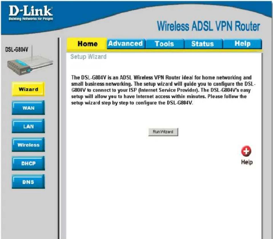
text_image
D-Link® Relicking Networks for People Wireless ADSL VPN Router Home Advanced Tools Status Help DSL-G804V Setup Wizard The DSL-G804V is an ADSL Wireless VPN Router ideal for home networking and small business networking. The setup wizard will guide you to configure the DSL-G804V to connect to your ISP (Internet Service Provider). The DSL-G804V's easy setup will allow you to have Internet access within minutes. Please follow the setup wizard step by step to configure the DSL-G804V. RunWizard HelpFigure 3-2. Home – Status Information window
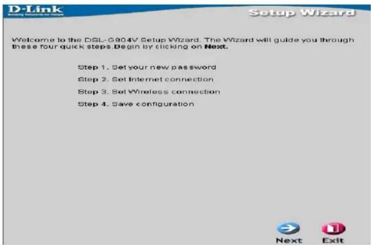
When the Router is used to provide Internet access it actually must first access your service provider's network, that is, it must communicate with computers and other routers owned by your service provider. These computers and routers then provide access to the Internet. The Router must be configured to communicate with the systems that give it access to the larger network. Click the Run Wizard tab; the Setup Wizard window will appear.
text_image
D-Link Setup Wizard Welcome to the DSL-G804V Setup Wizard. The Wizard will guide you through these four quick steps.Begin by clicking on Next. Step 1. Set your new password Step 2. Set Internet connection Step 3. Set Wireless connection Step 4. Save configuration Next ExitFigure 3-3. Home - Setup Wizard window
WAN
The WAN windows provide needed information to the WAN (Wide Area Network) Settings in order to get connected to your ISP (Internet Service Provider). The WAN settings are given by your ISP; please contact your ISP for more information if needed.

text_image
D-Link Building Networks for People Wireless ADSL VPN Router Home Advanced Tools Status Help ATM VC Setting VPI 0 VCI 32 WAN Settings Please select the appropriate option to connect to your ISP. PPPcE ( RFC2516, PPP over Ethernet ) PPPoE Username Password Service Name IP Address 0.0.0.0 (0.0.0.0:Obtain an IP address automatically) Authentication Protocol Chap(Auto) Connection Always On Idle Timeout 0 minutes RIP RIP v1 RIP v2 RIP v2 Multicast MTU 1492 NAT Enable Disable ATM ATM Class UBR Apply Cancel HelpFigure 3-4. WAN Setup window - PPPoE
ATM VC Setting
VC, known as Virtual Circuit or Virtual Channel, is a virtual path in which a communication session is established. Check with your ISP for information.
WAN Setting – Please select the appropriate option to connect to your ISP. There are five options: PPPoA (RFC 2864, PPP over AAL5), PPPoE (RFC2516, PPP over Ethernet), MPoA (RFC 1483/RFC 2684, Multiprotocol Encapsulation over AAL5), IPoA (RFC 1577, Classic IP and ARP over ATM) and Pure Bridge.
PPPoE (RFC2516, PPP over Ethernet)
Select this option if your ISP requires you to use the PPPoE (Point-to-Point Protocol over Ethernet) connection.
| Parameter | Description |
| Username | Enter your username given by your ISP. This is case sensitive and uses the format of "username" instead of username@ispname. |
| Password | Enter your password given by your ISP. This is case sensitive. |
| Service Name | (optional) This is for identification purpose. If this is requested, you will get informed by your ISP. Maximum input is 20 alphanumeric characters. |
| IP Address | (optional) This option is only available if you have given a fixed IP address from your ISP. Enter 0.0.0.0 to get a random assigned IP from your ISP;Username and Password must be entered. |
| Authentication Protocol | Default is Chap(Auto). Your ISP will advise you whether to use Chap or Pap. |
| Connection | How you like establish your PPPoE connection, Always on or Connect on Demand.Always on:If you want the router to establish a PPPoE session when starting up and to automatically re-establish the PPPoE session when disconnected by the ISP.Connect to Demand:If you want to establish a PPPoE session only when there is a packet requesting access to the Internet (i.e. when a program on your computer attempts to access the Internet). |
| Idle Timeout | Auto-disconnect the PPPoE connection when there is no activity on the line for a predetermined period of time. |
| RIP (Routing Information Protocol) | It is an interior routing protocol for router to exchange routing information.MTU (Maximum Transmission Unit):This is the size of largest datagram (excluding media-specific headers) that IP will attempt to send through the interface. The default setting is 1492. |
| NAT (Network Address Translation) | This allows multiple users to access the Internet through a single ISP account, sharing a single IP address. If users on your LAN have public IP addresses and can access the Internet directly, the NAT function can be disabled. |
| ATM Class | The Quality of Service for ATM layer. |
PPPoE - Advanced Options:
| Parameter | Description |
| LLC Header | Selects encapsulation mode, true for using LLC or false for using VC-Mux. |
| Create Route | This setting specifies whether a route is added to the system after IPCP (Internet Protocol Control Protocol) negotiation is completed. If set to enabled, a route will be created which directs packets to the remote end of the PPP link. |
| Specific Route | Specifies whether the route created when a PPP link comes up is a specific or default route. If set to enabled, the route created will only apply to packets for the subnet at the remote end of the PPP link. The address of this subnet is obtained during IPCP negotiation. |
| Subnet Mask | Sets the subnet mask used for the local IP interface connected to the PPP transport. If the value 0.0.0.0 is supplied, the netmask will be calculated from the class of the IP address obtained during IPCP negotiation. |
| Route Mask | Sets the subnet mask used by the route that is created when a PPP link comes up. If it is set to 0.0.0.0, the subnet mask is determined by the IP address of the remote end of the link. The class of the IP address is obtained during IPCP (Internet Protocol Control Protocol) negotiation. |
| MRU | Maximum Receive Unit. This is negotiated during the LCP protocol stage. |
| Discover Primary / Secondary DNS | This setting enables/disables whether the primary/secondary DNS server address is requested from a remote PPP peer using IPCP. The default setting for this command is enabled. |
| Give DNS to Relay | Controls whether the PPP Internet Protocol Control Protocol (IPCP) can request the DNS server IP address for a remote PPP peer. Once IPCP has discovered the DNS server IP address, it automatically gives the address to the local DNS relay so that a connection can be established. |
| Give DNS to Client | Controls whether the PPP Internet Protocol Control Protocol (IPCP) can request a DNS server IP address for a remote PPP peer. Once IPCP has discovered the DNS server IP address, it automatically gives the address to the local DNS client so that a connection can be established. |
| Give DNS to DHCP Server | Similar to the above, but gives the DNS server address to the DHCP server. |
| Discover Primary NBNS / Discover Secondary NBNS | This setting enables/disables whether the primary/secondary NBNS server address is requested from a remote PPP peer using IPCP. The default setting for this command is disabled. |
| Discover Subnet Mask | Specifies if the subnet mask given by IPCP negotiation process is to be used |
| Give Subnet Mask To DHCP Server | Enable to change your DHCP Server settings by using the given information in IPCP negotiation process. |
PPPoA (RFC2864, PPP over AAL5)
Select this option if your ISP requires you to use the PPPoA (Point-to-Point Protocol over ATM) connection.

text_image
D-Link Building Networks for People Wireless ADSL VPN Router DSL-G804V Home Advanced Tools Status Help ATM VC Setting VPI 0 VCI 32 WAN Settings Please select the appropriate option to connect to your ISP. PPPcA (RFC2864, PPP over AALS) PPPoA Username Password Service Name IP Address 0.0.0.0 (0.0.0.0:Obtain an IP address automatically) Authentication Protocol Chap(Auto) Connection Always On Idle Timeout 0 minutes RIP RIP v1 RIP v2 RIP v2 Multicast MTU 1500 NAT Enable Disable ATM ATM Class UER Apply Cancel HelpFigure 3-5. WAN Setup window - PPPoA
| Parameter | Description |
| Username | Enter your username given by your ISP. This is case sensitive and uses the format of "username" instead of username@ispname. |
| Password | Enter your password given by your ISP. This is case sensitive. |
| Service Name | (optional) This is for identification purpose. If this is requested, you will get informed by your ISP. Maximum input is 20 alphanumeric characters. |
| IP Address | (optional) This option is only available if you have given a fixed IP address from your ISP. Enter 0.0.0.0 to get a random assigned IP from your ISP; Username and Password must be entered. |
| Authentication Protocol | Default is Chap(Auto). Your ISP will advise you whether to use Chap or Pap. |
| Connection | How you like establish your PPPoA connection, Always on or Connect on Demand.Always on:If you want the router to establish a PPPoA session when starting up and to automatically re-establish the PPPoE session when disconnected by the ISP.Connect to Demand:If you want to establish a PPPoA session only when there is a packet requesting access to the Internet (i.e. when a program on your computer attempts to access the Internet). |
| Idle Timeout | Auto-disconnect the PPPoA connection when there is no activity on the line for a predetermined period of time. |
| RIP (Routing Information Protocol) | It is an interior routing protocol for router to exchange routing information. |
| MTU (Maximum Transmission Unit) | This is the size of largest datagram (excluding media-specific headers) that IP will attempt to send through the interface. The default setting is 1500. |
| NAT (Network Address Translation) | This allows multiple users to access the Internet through a single ISP account, sharing a single IP address. If users on your LAN have public IP addresses and can access the Internet directly, the NAT function can be disabled. |
| ATM Class | The Quality of Service for ATM layer. |
PPPoA - Advanced Options:
| Parameter | Description |
| LLC Header | Selects encapsulation mode, true for using LLC or false for using VC-Mux. |
| Create Route | This setting specifies whether a route is added to the system after IPCP (Internet Protocol Control Protocol) negotiation is completed. If set to enabled, a route will be created which directs packets to the remote end of the PPP link. |
| Specific Route | Specifies whether the route created when a PPP link comes up is a specific or default route. If set to enabled, the route created will only apply to packets for the subnet at the remote end of the PPP link. The address of this subnet is obtained during IPCP negotiation. |
| Subnet Mask | Sets the subnet mask used for the local IP interface connected to the PPP transport. If the value 0.0.0.0 is supplied, the netmask will be calculated from the class of the IP address obtained during IPCP negotiation. |
| Route Mask | Sets the subnet mask used by the route that is created when a PPP link comes up. If it is set to 0.0.0.0, the subnet mask is determined by the IP address of the remote end of the link. The class of the IP address is obtained during IPCP (Internet Protocol Control Protocol) negotiation. |
| MRU | Maximum Receive Unit. This is negotiated during the LCP protocol stage. |
| Discover Primary / Secondary DNS | This setting enables/disables whether the primary/secondary DNS server address is requested from a remote PPP peer using IPCP. The default setting for this command is enabled. |
| Give DNS to Relay | Controls whether the PPP Internet Protocol Control Protocol (IPCP) can request the DNS server IP address for a remote PPP peer. Once IPCP has discovered the DNS server IP address, it automatically gives the address to the local DNS relay so that a connection can be established. |
| Give DNS to Client | Controls whether the PPP Internet Protocol Control Protocol (IPCP) can request a DNS server IP address for a remote PPP peer. Once IPCP has discovered the DNS server IP address, it automatically gives the address to the local DNS client so that a connection can be established. |
| Give DNS to DHCP Server | Similar to the above, but gives the DNS server address to the DHCP server. |
| Discover Primary NBNS / Discover Secondary NBNS | This setting enables/disables whether the primary/secondary NBNS server address is requested from a remote PPP peer using IPCP. The default setting for this command is disabled. |
| Discover Subnet Mask | Specifies if the subnet mask given by IPCP negotiation process is to be used. |
| Give Subnet Mask To DHCP Server | Enable to change your DHCP Server settings by using the given information in IPCP negotiation process. |
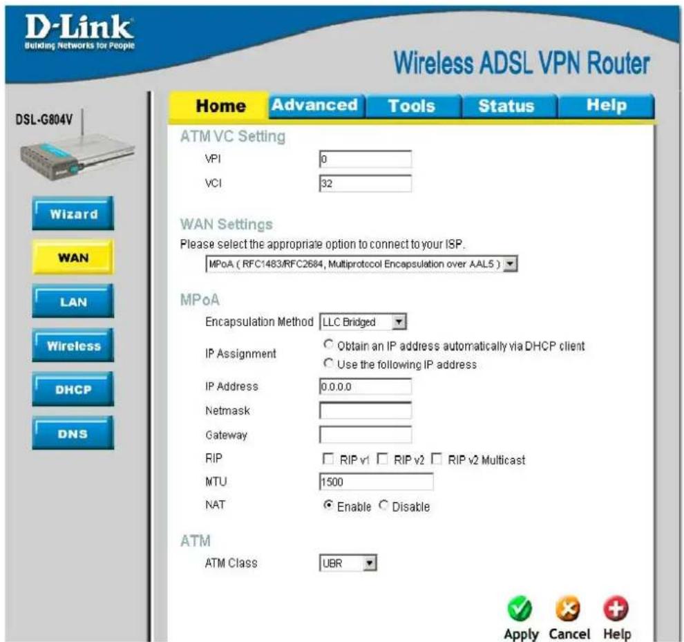
MPoA (RFC1483/RFC2684, Multi protocol Encapsulation over AAL5)
text_image
D-Link Building Networks for People Wireless ADSL VPN Router DSL-G804V Home Advanced Tools Status Help ATM VC Setting VPI 0 VCI 32 WAN Settings Please select the appropriate option to connect to your ISP. MPoA ( RFC1483/RFC2684, Multiprotocol Encapsulation over AAL5 ) MPoA Encapsulation Method LLC Bridged IP Assignment Obtain an IP address automatically via DHCP client Use the following IP address IP Address 0.0.0.0 Netmask Gateway RIP RIP v1 RIP v2 RIP v2 Multicast MTU 1500 NAT Enable Disable ATM ATM Class UBR Apply Cancel HelpFigure 3-6. WAN Setup window - MPoA
| Parameter | Description |
| Encapsulation Method | Select the encapsulation format, this is provided by your ISP. |
| IP Assignment | Please click Obtain an IP address automatically via DHCP client to enable the DHCP client function or click Specify an IP address to disable the DHCP client function, and specify the IP address, Netmask and Gateway manually. The setting of this item is specified by your ISP. |
| RIP (Routing Information Protocol) | It is an interior routing protocol for router to exchange routing information. |
| MTU (Maximum Transmission Unit) | This is the size of largest datagram (excluding media-specific headers) that IP will attempt to send through the interface. The default setting is 1500. |
| NAT (Network Address Translation) | This allows multiple users to access the Internet through a single ISP account, sharing a single IP address. If users on your LAN have public IP addresses and can access the Internet directly, the NAT function can be disabled. |
| ATM Class | The Quality of Service for ATM layer. |
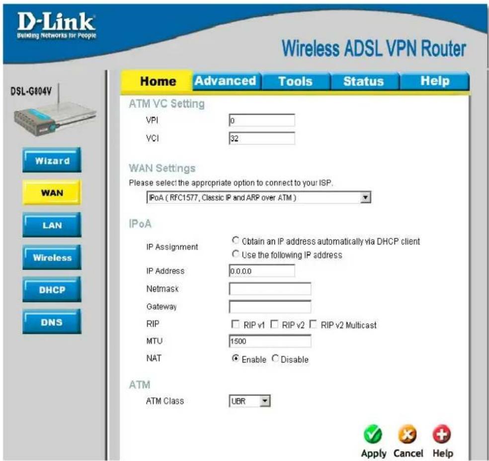
IPoA (RFC1577, Classic IP and ARP over ATM)
text_image
D-Link Building Networks for People Wireless ADSL VPN Router Home Advanced Tools Status Help ATM VC Setting VPI 0 VCI 32 WAN Settings Please select the appropriate option to connect to your ISP. IPoA ( RFC1577, Classic IP and ARP over ATM ) IPoA IP Assignment Obtain an IP address automatically via DHCP client Use the following IP address IP Address 0.0.0.0 Netmask Gateway RIP RIP v1 RIP v2 RIP v2 Multicast MTU 1500 NAT Enable Disable ATM ATM Class UBR Apply Cancel Help DSL-G804V Wizard WAN LAN Wireless DHCP DNSFigure 3-7. WAN Setup window - IPoA
| Parameter | Description |
| IP Assignment | Please click Obtain an IP address automatically via DHCP client to enable the DHCP client function or click Specify an IP address to disable the DHCP client function, and specify the IP address, Netmask and Gateway manually. The setting of this item is specified by your ISP. |
| RIP (Routing Information Protocol) | It is an interior routing protocol for router to exchange routing information. |
| MTU (Maximum Transmission Unit) | This is the size of largest datagram (excluding media-specific headers) that IP will attempt to send through the interface. The default setting is 1500. |
| NAT (Network Address Translation) | This allows multiple users to access the Internet through a single ISP account, sharing a single IP address. If users on your LAN have public IP addresses and can access the Internet directly, the NAT function can be disabled. |
| ATM Class | The Quality of Service for ATM layer. |
Pure Bridge

text_image
D-Link Building Networks for People Wireless ADSL VPN Router Home Advanced Tools Status Help DSL-G804V Wizard WAN LAN Wireless DHCP DNS ATM VC Setting VPI 0 VCI 32 WAN Settings Please select the appropriate option to connect to your ISP. Pure Bridge Pure Bridge Encapsulation Method LLC Bridged Ether Filter Type All Spanning Bridge Interface Enable Disable ATM ATM Class UBR Apply Cancel HelpFigure 3-8. WAN Setup window – Pure Bridge
| Parameter | Description |
| Encapsulation Method | Select the encapsulation format, this is provided by your ISP. |
| Ether Filter Type | Specify the type of Ethernet filtering performed by the named bridge interface. |
| Spanning Bridge Interface | Select Enable/Disable radio button to choose spanning tree function of modem. |
| ATM Class | The Quality of Service for ATM layer. |
LAN Settings
LAN (Local Area Network) setting is private to your internal network and cannot be seen from outside world, Internet. You may configure your LAN by given a LAN IP address to your network.
LAN Settings - LAN IP Configuration

text_image
D-Link Building Networks for People Wireless ADSL VPN Router Home Advanced Tools Status Help LAN Settings ● LAN IP Configuration ○ Ethernet Client Filter ○ Ethernet Port Setting Primary IP Address IP Address 192 . 168 . 1 . 1 Netmask 255 . 255 . 255 . 0 RIP □ RIP v1 □ RIP v2 □ RIP v2 Multicast Apply Cancel Help DSL-G804V Wizard WAN LAN Wireless DHCP DNSFigure 3-9. Home – LAN Settings (LAN IP Configuration)
| Parameter | Description |
| IP Address | Default setting is 192.168.1.1. |
| Subnet Mask | Default setting is 255.255.255.0. |
| RIP (Routing Information Protocol) | It is an interior routing protocol for router to exchange routing information. |
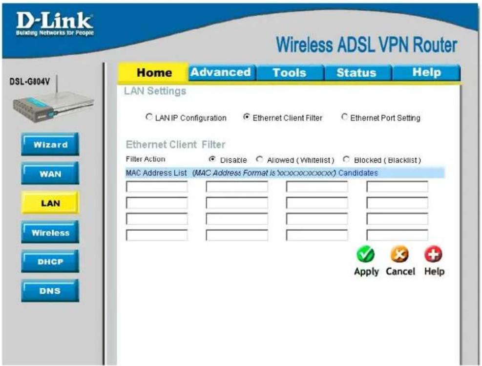
LAN Settings – Ethernet Client Filter
LAN (Local Area Network) setting is private to your internal network and cannot be seen from outside world, Internet. You may configure your LAN by given a LAN IP address to your network.
text_image
D-Link® Building Networks for People Wireless ADSL VPN Router Home Advanced Tools Status Help LAN Settings ○ LAN IP Configuration ○ Ethernet Client Filter ○ Ethernet Port Setting Ethernet Client Filter Filter Action ● Disable ○ Allowed (Whitelist) ○ Blocked (Blacklist) MAC Address List (MAC Address Format is xxxxxxxxxxxxxx) Candidates Apply Cancel Help DSL-G804V Wizard WAN LAN Wireless DHCP DNSFigure 3-10. Home - LAN Settings (Ethernet Client Filter)
| Parameter | Description |
| Filter Action | Select an appreciated filter action, Disable, Allowed (White list), and Blocked (Blacklist) |
| Disabled | This inactivates the Ethernet Client Filter function. |
| Allowed (White list) | This authorizes specific device accessing your LAN by insert the MAC Address in the space provided. Make sure you PC's MAC is listed. |
| Blocked (Blacklist) | Check to prevent unwanted device accessing your LAN by insert the MAC Address in the space provided. Make sure your PC's MAC is NOT listed. |
| Candidates | Active PC in LAN displays a list of individual Ethernet device's IP Address & MAC Address which connecting to the router. You can easily by checking the box next to the IP address to be blocked or allowed. Then Add to insert to the Ethernet Client Filter table. The maximum Ethernet client is 16. |
LAN Setting – Ethernet Port Setting
This allows you to configure the settings for the router's Ethernet ports to solve some of the compatibility problems that may be encountered while connecting to the Internet, as well allowing users to tweak the performance of their network.

text_image
D-Link Building Networks for People Wireless ADSL VPN Router Home Advanced Tools Status Help LAN Settings ○ LAN IP Configuration ○ Ethernet Client Filter ○ Ethernet Port Setting Port Setting Port1 Connection Type Auto Port2 Connection Type Auto Port3 Connection Type Auto Port4 Connection Type Auto IPv4 TOS Priority Control ○ Enable ● Disable Set High Priority TOS □ 63 □ 62 □ 61 □ 60 □ 59 □ 58 □ 57 □ 56 □ 55 □ 54 □ 53 □ 52 □ 51 □ 58 □ 49 □ 48 □ 47 □ 46 □ 45 □ 44 □ 43 □ 42 □ 41 □ 40 □ 39 □ 38 □ 37 □ 36 □ 35 □ 34 □ 33 □ 32 □ 31 □ 30 □ 29 □ 28 □ 27 □ 26 □ 25 □ 24 □ 23 □ 22 □ 21 □ 20 □ 19 □ 18 □ 17 □ 16 □ 15 □ 14 □ 13 □ 12 □ 11 □ 10 □ 9 □ 8 □ 7 □ 6 □ 5 □ 4 □ 3 □ 2 □ 1 □ 0 Apply Cancel HelpFigure 3-11. Home – LAN Settings (Ethernet Port Setting)
| Parameter | Description |
| Port # Connection Type | Five options to choose from: Auto, 10M half-duplex, 10M full-duplex, 100M half-duplex or 100M full-duplex. Sometimes, there are Ethernet compatibility problems with legacy Ethernet devices, and you can configure different types to solve compatibility issues. The default isAuto, which users should keep unless there are specific problems with PCs not being able to access your LAN. |
| IPv4 TOS priority Control (Advanced users) | TOS, Type of Services, is the 2^nd octet of an IP packet. Bits 6-7 of this octet are reserved and bit 0-2 are used to specify the priority (precedence) of the packet, and bits 3-5 are specified the delay, throughput and reliability. |
| Set High Priority TOS | This feature uses bits 0-2 to classify the packet’s priority. If the packet is high priority, it will flow first. Therefore, when this feature is enabled, the router’s Ethernet switch will check the 2^nd octet of each IP packet. If the value in the Precedence of TOS field matches the checked values in the table (0 to 7), this packet will be treated as high priority. |
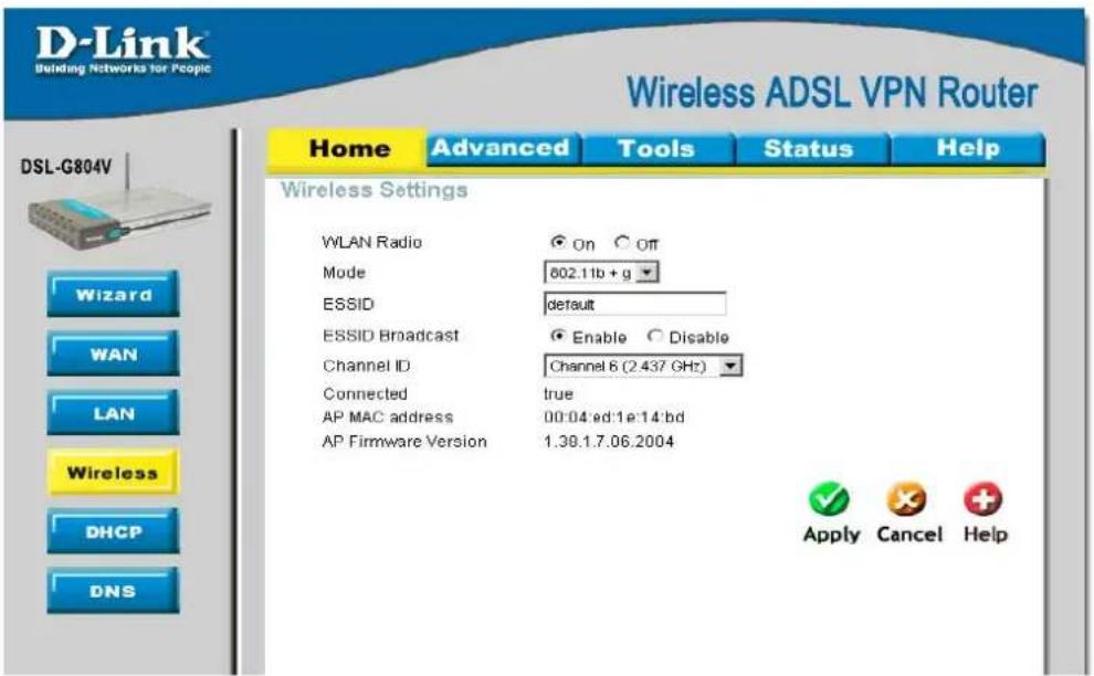
Wireless Settings
text_image
D-Link Building Networks for People Wireless ADSL VPN Router Home Advanced Tools Status Help DSL-G804V Wizard WAN LAN Wireless DHCP DNS Wireless Settings WLAN Radio ● On ○ Off Mode 802.11b + g ESSID Protein default ESSID Broadcast ● Enable ○ Disable Channel ID Channel 6 (2.437 GHz) Connected Protein true AP MAC address 00:04'ed:1e:14'bd AP Firmware Version 1.38.1.7.06.2004 Apply Cancel HelpFigure 3-12. Home – Wireless Settings
| Parameter | Description |
| WLAN Radio | Default setting is set to On. If you do not have any wireless, both 802.11g and 802.11b, device in your network, select Off. |
| Mode | The default setting is 802.11b+g (Mixed mode). If you do not know or have both 11g and 11b devices in your network, then keep the default in mixed mode. From the drop-down manual, you can select 802.11g if you have only 11g card. If you have only 11b card, then select 802.11b. |
| ESSID | This is the Network ID is used for identifying the WLAN. For security propose, change the initial ESSID, default, to a unique ID name to the AP which is already built-in to the router's wireless interface. It is case sensitive and must not excess 32 characters. Make sure your wireless clients have exactly the ESSID as the device, in order to get connected to your network. Client stations can roam freely over this product and other Access Points that have the same Network ID. |
| ESSID Broadcast | It is function in which transmits its ESSID to the air so that when wireless client searches for a network, router can then be discovered and recognized. Default setting is Enable. |
| Regulation Domain | There are seven Regulation Domains for you to choose from, including North America (N.America), Europe, France, etc. The Channel ID will be different based on this setting. |
| Channel ID | The radio channel number. The permissible channels depend on the Regulatory Domain.(The factory setting is channel 6) |
| Connected | Representing in true or false. That it is the connection status between the system and the build-in wireless card. |
| AP MAP address | It is a unique hardware address of the Access Point. |
| AP Firmware Version | The Access Point firmware version. |
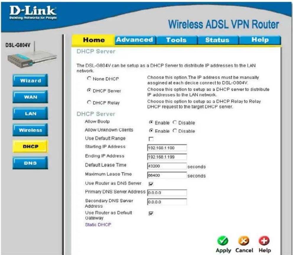
DHCP Server
DHCP stands for Dynamic Host Control Protocol. The DHCP protocol allows your router to dynamically assign IP addresses to PCs on your network if they are configured to obtain IP addresses automatically.
text_image
D-Link Building Networks for People Wireless ADSL VPN Router Home Advanced Tools Status Help DHCP Server The DSL-G804V can be setup as a DHCP Server to distribute IP addresses to the LAN network. None DHCP Choose this option. The IP address must be manually assigned at each device connect to DSL-G804V. DHCP Server Choose this option to setup as a DHCP server to distribute IP addresses to the LAN network. DHCP Relay Choose this option to setup as a DHCP Relay to Relay DHCP request to the target DHCP server. DHCP Server Allow Bootp Enable Disable Allow Unknown Clients Enable Disable Use Default Range Starting IP Address 192.168.1.100 Ending IP Address 192.168.1.199 Default Lease Time 43200 seconds Maximum Lease Time 86400 seconds Use Router as DNS Server ✓ Primary DNS Server Address 0.0.0.0 Secondary DNS Server Address 0.0.0.0 Use Router as Default Gateway ✓ Static DHCP Apply Cancel HelpFigure 3-13. Home - DHCP Server
None DHCP
The DHCP Server is disabled; you will need to manually assign a fixed IP address to each PCs on your network, and set the default gateway for each PCs to the IP address of the router.
DHCP Server
You can configure parameters of the DHCP Server including the IP pool (starting IP address and ending IP address to be allocated to PCs on your network), lease time for each assigned IP address (the period of time the IP address assigned will be valid), DNS IP address and the gateway IP address. These details are sent to the DHCP client (i.e. your PC) when it requests an IP address from the DHCP server. If you check “Use Router as a DNS Server”, the ADSL Router will perform the domain name lookup, find the IP address from the outside network automatically and forward it back to the requesting PC in the LAN (your Local Area Network).
Static DHCP
It is used to allow DHCP server to assign the same IP to specific MAC address. This is useful when you setup public servers (Web Server, FTP Server, for instance) inside LAN.

text_image
D-Link Building Networks for People Wireless ADSL VPN Router Home Advanced Tools Status Help Static DHCP Static DHCP is used to allow DHCP server to assign same IP to specific MAC address. Name IP Address MAC Address 00:00:00:00:00:00 Maximum Lease Time Back Apply Cancel Help Name IP Address MAC Address Maximum Lease TimeFigure 3-14. Home - DHCP Server (Static DHCP)
| Parameter | Description |
| Name | The name referencing the static IP assignment. |
| IP Address | The IP address for the specific node in LAN. |
| MAC Address | The MAC address of the specific node in LAN. |
| Maximum Lease Time | The maximum time interval you allow the specific MAC user to obtain this IP address. |
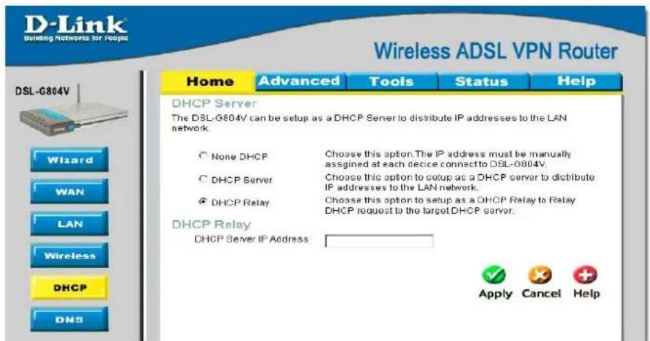
DHCP Relay
You can enter the IP address of the DHCP server that will assign an IP address back to the DHCP client in the LAN. Use this function only if advised to do so by your network administrator or ISP.
text_image
D-Link Building Networks for People Wireless ADSL VPN Router DSL-G804V Home Advanced Tools Status Help DHCP Server The DSL-G804V can be setup as a DHCP Server to distribute IP addresses to the LAN network. None DHCP Choose this option. The IP address must be manually assigned at each device connect to DSL-0804V. DHCP Server Choose this option to setup as a DHCP server to distribute IP addresses to the LAN network. DHCP Relay Choose this option to setup as a DHCP Relay to Relay DHCP request to the target DHCP server. DHCP Relay DHCP Server IP Address Apply Cancel HelpFigure 3-15. Home - DHCP Server (DHCP Relay)
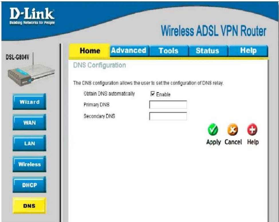
DNS Configuration
A Domain Name System (DNS) contains a mapping table for domain name and IP addresses. On the Internet, every host has a unique and user-friendly name (domain name) such as www.helloworld.com and an IP address. An IP address is a 32-bit number in the form of xxx.xxx.xxx.xxx, for example 192.168.1.1. You can think of an IP address as a telephone number for devices on the Internet, and the DNS will allow you to find the telephone number for any particular domain name. As an IP Address is hard to remember, the DNS converts the friendly name into its equivalent IP Address.
text_image
D-Link Building Networks for People Wireless ADSL VPN Router DSL-G804V Home Advanced Tools Status Help DNS Configuration The DNS configuration allows the user to set the configuration of DNS relay. Obtain DNS automatically ☑ Enable Primary DNS Secondary DNS Apply Cancel HelpFigure 3-16. Home – DNS Configuration
You can obtain a Domain Name System (DNS) IP address automatically if your ISP has provided it when you logon, check the Enable box. Usually when you choose PPPoE or PPPoA as your WAN - ISP protocol, the ISP will provide the DNS IP address automatically. You may leave the configuration field blank.
Alternatively, your ISP may provide you with an IP address of their DNS. If this is the case, you must enter the DNS IP address manually

Advanced Router Management
Click the Advanced tab to access menus used to configure Virtual Server, Firewall, VPN, DDNS, Routing, Wireless, ADSL, IP QoS, Time Schedule, Email, Device and IGMP.
Virtual Server
NAT can act as a “natural” Internet firewall; your router protects your network from being accessed by outside users. When using NAT, all incoming connection attempts will point to your router, unless you specifically create Virtual Server entries to forward those ports to a PC on your network. Virtual Sever utilizes protocol, TCP/IP and UDP types, which is port with 16-bit number that used to identify which the application program (usually a server) should be delivered from an incoming connections should be delivered to. Some ports have numbers that are pre-assigned to them by the IANA (the Internet Assigned Numbers Authority), and these are referred to as “well-known ports”. Servers follow the well-known port assignments so clients can locate them.

If you have disabled the NAT option in the WAN-ISP section, the Virtual Server function will hence be invalid.

If the DHCP server option is enabled, you have to be very careful in assigning the IP addresses of the virtual servers in order to avoid conflicts. The easiest way of configuring Virtual Servers is to manually assign static IP address to each virtual server PC, with an address that does not fall into the range of IP addresses that are to be issued by the DHCP server. You can configure the virtual server IP address manually, but it must still be in the same subnet as the router.
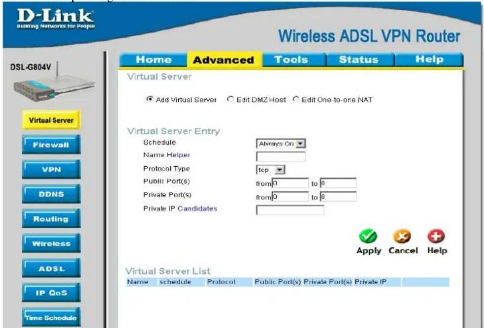
Add Virtual Server
When your router needs to allow outside users to access internal servers, e.g. a web server, FTP server, Email server or game server, the router can act as a "virtual server". You can set up a local server with a specific port number for the service to use, e.g. web/HTTP (port 80), FTP (port 21), Telnet (port 23), SMTP (port 25), or POP3 (port 110). When an incoming access request to the router for a specified port is received, it will be forwarded to the corresponding internal server.
text_image
D-Link Building Networks for People Wireless ADSL VPN Router Home Advanced Tools Status Help Virtual Server Add Virtual Server Edit DMZ Host Edit One-to-one NAT Virtual Server Entry Schedule Always On Name Helper Protocol Type tcp Public Port(s) from 0 to 0 Private Port(s) from 0 to 0 Private IP Candidates Apply Cancel Help Virtual Server List Name schedule Protocol Public Port(s) Private Port(s) Private IP DSL-G804V Virtual Server Firewall VPN DDNS Routing Wireless ADSL IP QoS Time ScheduleFigure 4-1. Virtual Server – Add Virtual Server
| Parameter | Description |
| Schedule | A self-defined time period to enable your virtual server. You may specify a time schedule or Always on for the usage of this Virtual Server Entry. For setup and detail, refer to Time Schedule section. |
| Name | Users-defined description to identify this entry or click Helper to select existing predefined rules. |
| Helper: 20 predefined rules are available. Click the Radio button to select the rule; Application, Protocol and External/Redirect Ports will be filled after the selection. | |
| Protocol Type | It is the supported protocol for the virtual server. In addition to specifying the port number to be used, you will also need to specify the protocol used. The protocol used is determined by the particular application. Most applications will use TCP or UDP. |
| Public Port(s) | The Port number on the Remote/WAN side used when accessing the virtual server. |
| Private Port(s) | The Port number used by the Local server in the LAN network. |
| Private IP | The private IP in the LAN network that will be providing the virtual server application. |
| Candidates: List all existing PCs connecting to the network. You may assign a PC with IP address and MAC from this list. |
Example:
If you like to remote access your Router through the Web/HTTP at all time, you would need to enable port number 80 (Web/HTTP) and map to Router's IP Address. Then all incoming HTTP requests from you (Remote side) will be forwarded to the Router with IP address of 192.168.0.1. Since port number 80 has already been predefined, next to the Application click Helper. A list of predefined rules window will pop and select HTTP_Sever.
Name: HTTP_Sever
Time Schedule: Always On
Protocol: tcp
External Port: 80-80
Redirect Port: 80-80
IP Address: 192.168.0.1
Virtual Server List
| Name | schedule | Protocol | Public Port(s) | Private Port(s) | Private IP | |
| Http_Sever Always On | tcp | 80 - 80 | 80 - 80 | 192.168.0.1 |  | |
Edit DMZ Host
The DMZ Host is a local computer exposed to the Internet. When setting a particular internal IP address as the DMZ Host, all incoming packets will be checked by the Firewall and NAT algorithms then passed to the DMZ host, when a packet received does not use a port number used by any other Virtual Server entries.

This Local computer exposing to the Internet may face varies of security risks.
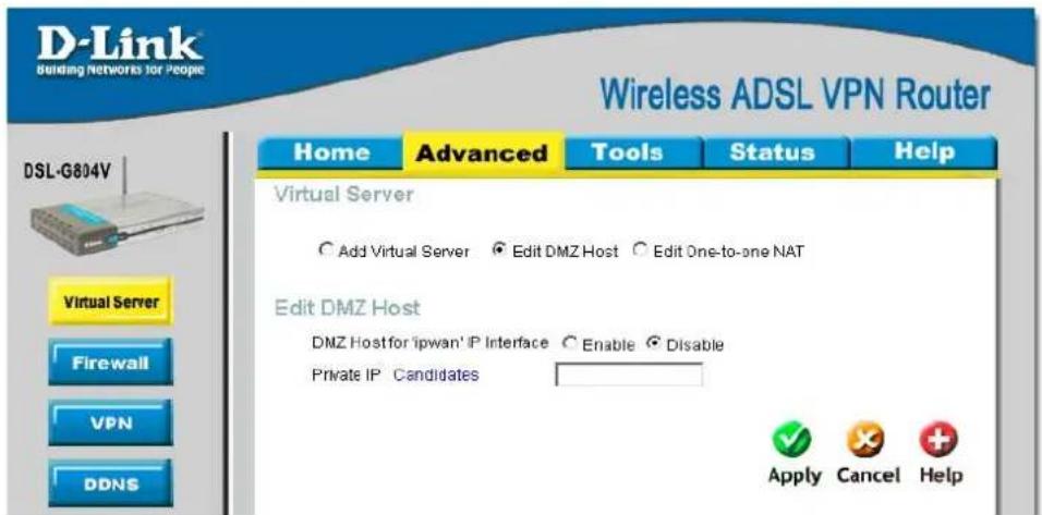
text_image
D-Link Building Networks for People Wireless ADSL VPN Router Home Advanced Tools Status Help Virtual Server Add Virtual Server Edit DMZ Host Edit One-to-one NAT Edit DMZ Host DMZ Host for 'ipwan' IP Interface Enable Disable Private IP Candidates Apply Cancel HelpFigure 4-2. Virtual Server – Edit DMZ Host
| Parameter | Description |
| DMZ Host for ‘ipwan’ IP Interface | Disable or activate the DMZ function. |
| Private IP | Give a static IP address to the DMZ Host when Enabled radio button is checked. Be aware that this IP will be exposed to the WAN/Internet.Candidates: List all existing PCs connecting to the network. You may assign a PC with IP address and MAC from this list. |
| Edit One-to-One NAT |
One-to-One NAT maps a specific private/local IP address to a global/public IP address. If you have multiple public/WAN IP addresses from you ISP, you are eligible for One-to-One NAT to utilize these IP addresses.

text_image
D-Link Building Networks for People Wireless ADSL VPN Router Home Advanced Tools Status Help Virtual Server Add Virtual Server Edit DMZ Host Edit One-to-one NAT Global IP Pool in 'ipwan' IP interface NAT Type Disable Public to Private Subnet Public to DMZ Zone Global IP Addresses Subnet IP Range IP Address Netmask Apply Cancel Help One-to-one NAT Table Add Entry Name schedule Protocol Public Port(s) Private Port(s) Private IPFigure 4-3. Virtual Server – Edit One-to-One NAT
| Parameter | Description |
| NAT Type | Select desired NAT type. As set in default setting, it disables the One-to-One NAT function. |
| Global IP Addresses | Subnet: The subnet of the public/WAN IP address given by your ISP. If your ISP has provided this information, you may insert it here. Otherwise, use IP Range method.IP Range: The IP address range of your public/WAN IP addresses. For example, IP: 192.168.1.1, end IP: 192.168.1.10. |
| Add Entry (Virtual Server Entry) | You can create a new One-to-One NAT rule.Schedule:A self-defined time period to enable your virtual server. You may specify a time schedule or Always on for the usage of this Virtual Server Entry. For setup and detail, refer to Time Schedule section..Name: Users-defined description to identify this entry or click Helper to select existing predefined rules.Protocol Type: It is the supported protocol for the virtual server. In addition to specifying the port number to be used, you will also need to specify the protocol used. The protocol used is determined by the particular application.Public Port(s): The Port number on the Remote/WAN side used when accessing the virtual server.Private Port(s): The Port number used by the Local server in the LAN networkPrivate IP: The private IP in the LAN network which will be providing the virtual server application. |
Firewall
Firewall is used to allow or deny traffic from passing through your local network. If Firewall is enabled, the Packet Filter will be used to filter packets based-on Applications (Port) or IP addresses.
General Setting
VC, known as Virtual Circuit or Virtual Channel, is a virtual path in which a communication session is established. Check with your ISP for information.
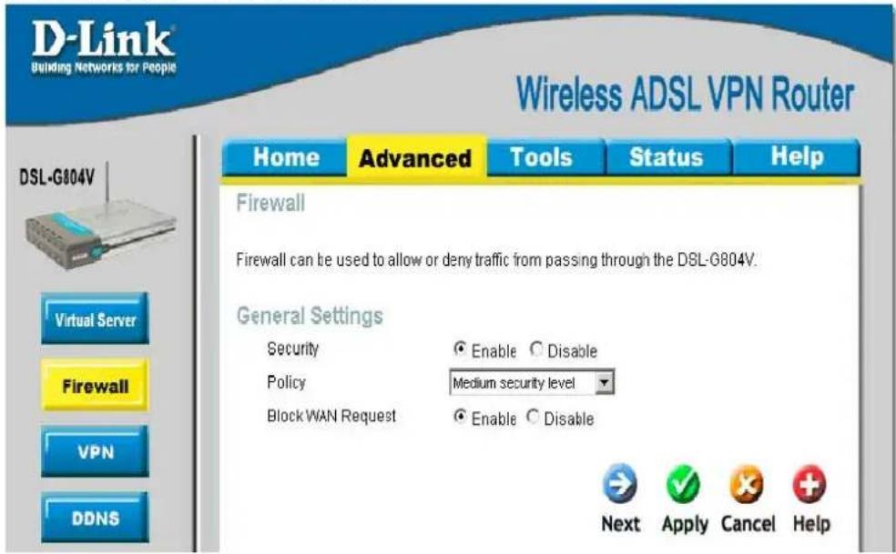
text_image
D-Link Building Networks for People Wireless ADSL VPN Router Home Advanced Tools Status Help DSL-G804V Firewall Firewall can be used to allow or deny traffic from passing through the DSL-G804V. General Settings Security Enable Disable Policy Medium security level Block WAN Request Enable Disable Next Apply Cancel HelpFigure 4-4. Firewall - General Setting

Any remote user who is attempting to perform this action may result in blocking all the accesses to configure and manage of the device from the Internet.
| Parameter | Description |
| Security | Disable or activate the Firewall function. |
| Policy | There are four options when you enable the Firewall, they are:All blocked/User-defined:no pre-defined port or address filter rules by default, meaning that all inbound (Internet to LAN) and outbound (LAN to Internet) packets will be blocked.Users have to add their own filter rules for further access to the Internet.High/Medium/Low security level:the predefined port filter rules for High, Medium and Low security are displayed in Port Filters of Packet Filter. |
| Block WAN Request | This is a stand-alone function and not related to whether security is enabled or disabled. Mostly it is for preventing any scan tools from WAN site initiated by a hacker. |
| Click Applyand then click Nextto process. | |
Packet Filter
This function is only available when the Firewall is enabled and one of these four security levels is chosen (All blocked, High, Medium and Low). The predefined port filter rules in the Packet Filter must modify accordingly to the level of Firewall, which is selected. See Table1: Predefined Port Filter for more detailed information.
Filter List
| Rule Name | Time Schedule | Source IP / Netmask | Protocol | Source port(s) | Inbound | |
| Destination IP / Netmask | Destination port(s) | Outbound | ||||
| mei_http | Always On | 0.0.0.0 / 0.0.0.0 | TCP | 0 ~ 65535 | Block | |
| 0.0.0.0 / 0.0.0.0 | 80 ~ 80 | Allow | ||||
| mei_dns | Always On | 0.0.0.0 / 0.0.0.0 | UDP | 0 ~ 65535 | Block | |
| 0.0.0.0 / 0.0.0.0 | 53 ~ 53 | Allow | ||||
| mei_tdns | Always On | 0.0.0.0 / 0.0.0.0 | TCP | 0 ~ 65535 | Block | |
| 0.0.0.0 / 0.0.0.0 | 53 ~ 53 | Allow | ||||
| mei_ftp | Always On | 0.0.0.0 / 0.0.0.0 | TCP | 0 ~ 65535 | Block | |
| 0.0.0.0 / 0.0.0.0 | 21 ~ 21 | Allow | ||||
| mei_tnet | Always On | 0.0.0.0 / 0.0.0.0 | TCP | 0 ~ 65535 | Block | |
| 0.0.0.0 / 0.0.0.0 | 23 ~ 23 | Allow | ||||
| mei_smtp | Always On | 0.0.0.0 / 0.0.0.0 | TCP | 0 ~ 65535 | Block | |
| 0.0.0.0 / 0.0.0.0 | 25 ~ 25 | Allow | ||||
| mei_pop3 | Always On | 0.0.0.0 / 0.0.0.0 | TCP | 0 ~ 65535 | Block | |
| 0.0.0.0 / 0.0.0.0 | 110 ~ 110 | Allow | ||||
| mei_nntp | Always On | 0.0.0.0 / 0.0.0.0 | TCP | 0 ~ 65535 | Block | |
| 0.0.0.0 / 0.0.0.0 | 119 ~ 119 | Allow | ||||
| mei_rav | Always On | 0.0.0.0 / 0.0.0.0 | UDP | 0 ~ 65535 | Allow | |
| 0.0.0.0 / 0.0.0.0 | 7070 ~ 7070 | Allow | ||||
| mei_icmp | Always On | 0.0.0.0 / 0.0.0.0 | ICMP | N/A | Block | |
| 0.0.0.0 / 0.0.0.0 | N/A | Allow |
Example: Predefined Port Filters Rules
The predefined port filter rules for High, Medium and Low security levels are listed. See Table 1.

Firewall – All Blocked/User-defined, you must define and create the port filter rules yourself. No predefined rule is set.
Table 1: Predefined Port Filter
| Application | Protocol | Port Number | Firewall - High | Firewall - Medium | Firewall – Low |
| Start End | Inbound | Outbound | Inbound | Outbound | Inbound Outbound | ||||
| HTTP(80) | TCP(6) 80 | 80 | NO | YES | NO | YES | NO | YES | |
| DNS (53) | UDP(17) 53 | 53 NO | YES | NO | YES | YES YES | |||
| DNS (53) | TCP(6) 53 | 53 NO | YES | NO | YES | YES YES | |||
| FTP(21) | TCP(6) 21 | 21 NO NO NO | YES | NO | YES | ||||
| Telnet(23) | TCP(6) 23 | 23 NO NO NO | YES | NO | YES | ||||
| SMTP(25) | TCP(6) | 25 | 25 | NO | YES | NO | YES | NO | YES |
| POP3(110) | TCP(6) | 110 | 110 | NO | YES | NO | YES | NO | YES |
| NEWS(119) | TCP(6) | 119 | 119 | NO | NO | NO | YES | NO | YES |
| RealAudio (7070) | UDP(17) | 7070 | 7070 | NO | NO | YES | YES | YES YES | |
| PING | ICMP(1) | N/A | N/A | NO | YES | NO | YES | NO | YES |
| H.323(1720) | TCP(6) | 1720 | 1720 | NO | NO | NO | YES | YES YES | |
| T.120(1503) | TCP(6) | 1503 | 1503 | NO | NO | NO | YES | YES YES | |
| SSH(22) | TCP(6) | 22 | 22 | NO | NO | NO | YES | YES YES | |
| NTP(123) | UDP(17) | 123 | 123 | NO | YES | NO | YES | NO | YES |
| HTTPS(443) | TCP(6) | 443 | 443 | NO | NO | NO | YES | NO | YES |
Inbound: Internet to LAN
Outbound: LAN to Internet.
Packet Filter - Add TCP/UDP Filter

text_image
D-Link Building Networks for People Wireless ADSL VPN Router Home Advanced Tools Status Help Firewall Firewall can be used to allow or deny traffic from passing through the DSL-G804V. Add TCP/UDP Filter Add Raw IP Filter Intrusion Detection URL Filter Firewall Log Add TCP/UDP Filter Name Schedule Always On Source IP Address(es) 0.0.0 Netmask 0.0.0 Destination IP Address(es) 0.0.0 Netmask 0.0.0 Type TCP Source port 0 - 65535 Destination port 0 - 65535 Inbound Allow Outbound Allow Apply Cancel Help DSL-G804V Virtual Server Firewall VPN DDNS Routing Wireless ADSL IP QoSFigure 4-5. Firewall - Add TCP/UDP Filter
| Parameter | Description |
| Name | A user defined name for identifying the rule. |
| Schedule | It is self-defined time period. You may specify a time schedule for your prioritization policy. For setup and detail, refer to Time Schedule section. |
| Sources IP Adderss(es) / Destination IP Address(es) | This is the Address-Filter used to allow or block traffic to/from particular IP address (es). Selecting the Subnet Mask of the IP address range you wish to allow/block the traffic to or form; set IP address and Subnet Mask to 0.0.0.0 to inactive the Address-Filter rule. |

To block access, to / from a single IP address, enter that IP address as the Host IP Address and use a Host Subnet Mask of "255.255.255.255".
Source port / Destination port
This is the Address-Filter used to allow or block traffic to/from particular IP address(es). Selecting the Subnet Mask of the IP address range you wish to allow/block the traffic to or form; set IP address and Subnet Mask to 0.0.0.0 to inactive the Address-Filter rule.
Inbound / Outbound
Select Allow or Block the access to the Internet ("Outbound") or from the Internet ("Inbound").
Packet Filter - Add Raw Filter
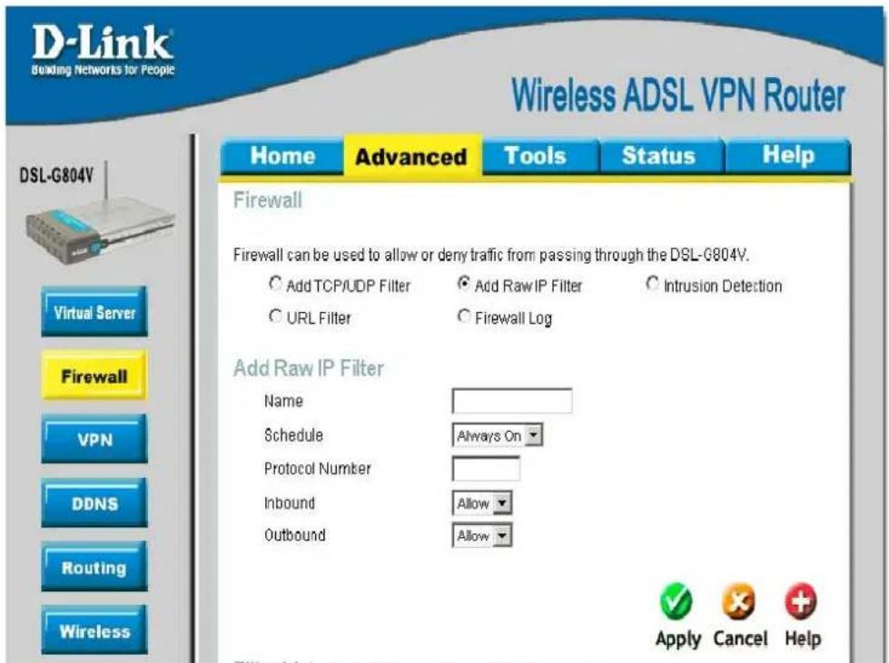
text_image
D-Link Building Networks for People Wireless ADSL VPN Router Home Advanced Tools Status Help Firewall Firewall can be used to allow or deny traffic from passing through the DSL-G804V. Add TCP/UDP Filter Add Raw IP Filter Intrusion Detection URL Filter Firewall Log Add Raw IP Filter Name Schedule Always On Protocol Number Inbound Allow Outbound Allow Apply Cancel Help DSL-G804V Virtual Server Firewall VPN DDNS Routing WirelessFigure 4-6. Firewall - Add Raw Filter
| Parameter | Description |
| Name | A user defined name for identifying the rule. |
| Schedule | It is self-defined time period. You may specify a time schedule for your prioritization policy. For setup and detail, refer to Time Schedule section. |
| Protocol Number | Insert the port number, i.e. GRE 47. |
| Inbound / Outbound | Select Allow or Block the access to the Internet (“Outbound”) or from the Internet (“Inbound”). |
Configuring Packet Filter:
- Click Port Filters. You will then be presented with the predefined port filter rules screen (in this case for the low security level), shown below:

You may click Edit the predefined rule instead of Delete it. This is an example to show to how you add a filter on your own.
| Rule Name | Time Schedule | Source IP / Netmask | Protocol | Source port(s) | Inbound | |
| Destination IP / Netmask | Destination port(s) | Outbound | ||||
| mei_http | Always On | 0.0.0.0 / 0.0.0.0 | TCP | 0 ~ 65535 | Block | |
| 0.0.0.0 / 0.0.0.0 | 80 ~ 80 | Allow | ||||
| mei_dns | Always On | 0.0.0.0 / 0.0.0.0 | UDP | 0 ~ 65535 | Block | |
| 0.0.0.0 / 0.0.0.0 | 53 ~ 53 | Allow | ||||
| mei_tdns | Always On | 0.0.0.0 / 0.0.0.0 | TCP | 0 ~ 65535 | Block | |
| 0.0.0.0 / 0.0.0.0 | 53 ~ 53 | Allow | ||||
| mei_ftp | Always On | 0.0.0.0 / 0.0.0.0 | TCP | 0 ~ 65535 | Block | |
| 0.0.0.0 / 0.0.0.0 | 21 ~ 21 | Allow | ||||
| mei_tnet | Always On | 0.0.0.0 / 0.0.0.0 | TCP | 0 ~ 65535 | Block | |
| 0.0.0.0 / 0.0.0.0 | 23 ~ 23 | Allow | ||||
| mei_smtp | Always On | 0.0.0.0 / 0.0.0.0 | TCP | 0 ~ 65535 | Block | |
| 0.0.0.0 / 0.0.0.0 | 25 ~ 25 | Allow | ||||
| mei_pop3 | Always On | 0.0.0.0 / 0.0.0.0 | TCP | 0 ~ 65535 | Block | |
| 0.0.0.0 / 0.0.0.0 | 110 ~ 110 | Allow | ||||
| mei_nntp | Always On | 0.0.0.0 / 0.0.0.0 | TCP | 0 ~ 65535 | Block | |
| 0.0.0.0 / 0.0.0.0 | 119 ~ 119 | Allow | ||||
| mei_rav | Always On | 0.0.0.0 / 0.0.0.0 | UDP | 0 ~ 65535 | Allow | |
| 0.0.0.0 / 0.0.0.0 | 7070 ~ 7070 | Allow | ||||
| mei_icmp | Always On | 0.0.0.0 / 0.0.0.0 | ICMP | N/A | Block | |
| 0.0.0.0 / 0.0.0.0 | N/A | Allow |
-
Click Delete to delete the existing HTTP rule.
-
Click Add TCP/UDP Filter.
Firewall
Firewall can be used to allow or deny traffic from passing through the DSL-G804V.
- Add TCP/UDP Filter
○ Add Raw IP Filter
○ Intrusion Detection
C URL Filter
○ Firewall Log
Input the Rule Name, Time Schedule, Source/Destination IP, Type, Source/Destination Port, Inbound and Outbound.
Intrusion Detection.
The router's Intrusion Detection System (IDS) is used to detect hacker attacks and intrusion attempts from the Internet. If the IDS function of the firewall is enabled, inbound packets are filtered and blocked depending on whether they are detected as possible hacker attacks, intrusion attempts or other connections that the router determines to be suspicious.

text_image
D-Link Building Networks for People Wireless ADSL VPN Router Home Advanced Tools Status Help Firewall Firewall can be used to allow or deny traffic from passing through the DSL-G804V. Add TCP/UDP Filter Add Raw IP Filter_Intrusion Detection URL Filter Firewall Log Intrusion Detection Intrusion Detection Enable Disable Victim Protection Block Duration 600 seconds Scan Attack Block Duration 86400 seconds DOG Attack Block Duration 1900 seconds Maximum TCP Open Handshaking Count 100 per second Maximum Ping Count 15 per second Maximum ICMP Count 100 per second Clear Blocklist Apply Cancel Help DSL-G804V Virtual Server Firewall VPN DDNS Routing Wireless ADSL IP QoSFigure 4-7. Firewall – Intrusion Detection
| Parameter | Description |
| Intrusion Detection | Disable or activate this function. |
| Victim Protection Block Duration (seconds) | This is the duration for blocking Smurf attacks. |
| Scan Attack Block Duration (seconds) | This is the duration for blocking hosts that attempt a possible Scan attack. Scan attack types include X'mas scan, IMAP SYN/FIN scan and similar attempts |
| DOS Attack Block Duration (seconds) | This is the duration for blocking hosts that attempt a possible Denial of Service (DoS) attack. Possible DoS attacks this attempts to block include Ascend Kill and WinNuke. |
| Maximum TCP Open Handshaking Count (per second)) | This is a threshold value to decide whether a SYN Flood attempt is occurring or not. |
| Maximum Ping Count (per second) | This is a threshold value to decide whether an ICMP Echo Storm is occurring or not. |
| Maximum ICMP Count (per second) | This is a threshold to decide whether an ICMP flood is occurring or not. |
| Clear Blocklist | If the router detects a possible attack, the source IP or destination IP address will be added to the Blacklist. Any further attempts using this IP address will be blocked for the time period specified as the Block Duration. Click it to remove the detected IP addresses from the blocklist. |
URL Filter
URL (Uniform Resource Locator - e.g. an address in the form of http://www.abcde.com or http://www.example.com) filter rules allow you to prevent users on your network from accessing particular websites by their URL. There are no predefined URL filter rules; you can add filter rules to meet your requirements.
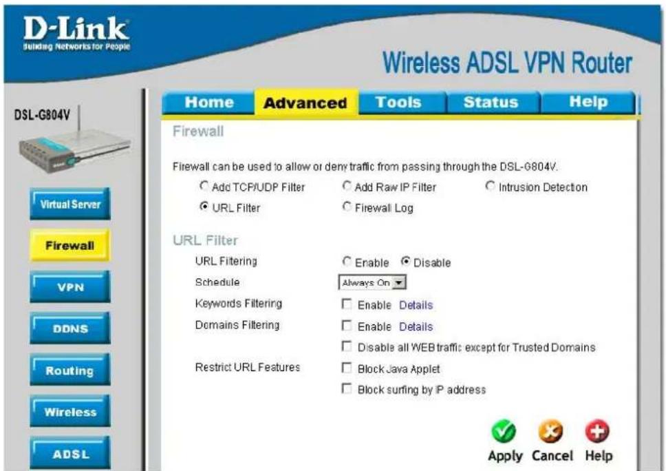
text_image
D-Link Building Networks for People Wireless ADSL VPN Router Home Advanced Tools Status Help DSL-G804V Firewall Firewall can be used to allow or deny traffic from passing through the DSL-G804V. ○ Add TCP/UDP Filter ○ Add Raw IP Filter ○ Intrusion Detection ● URL Filter ○ Firewall Log URL Filter URL Filtering ○ Enable ○ Disable Schedule Always On Keywords Filtering □ Enable Details Domains Filtering □ Enable Details Restrict URL Features □ Disable all WEB traffic except for Trusted Domains Block Java Applet □ Block surfing by IP address Apply Cancel HelpFigure 4-8. Firewall - URL Filter
| Parameter | Description |
| URL Filtering | Disable or activate this function. |
| Schedule | It is self-defined time period. Check Disable radio button to inactivate the URL Filtering function, or keep the URL Filtering as Always on. You may also specify a time schedule for your prioritization policy. For setup and detail, refer to Time Schedule section. |
| Keywords Filtering | Allows blocking by specific keywords within a particular URL rather than having to specify a complete URL (e.g. to block any image called “advertisement.gif”). When enabled, your specified keywords list will be checked to see if any keywords are present in URLs accessed to determine if the connection attempt should be blocked. |
| Domain Filtering | This function checks the domain name only, not the IP address, in URLs accessed against your list of domains to block or allow. If it is matched, the URL request will be sent (Trusted) or dropped (Forbidden). For this function to be activated, both Enable and Disable all WEB traffic except for Trusted Domain must be checked. |
| Restrict URL Features | This function enhances the restriction to your URL rules.Block Java Applet: This function can block Web content which includes the Java Applet. It is to prevent someone who wants to damage your system via standard HTTP.Block surfing by IP address: Preventing someone who uses the IP address as URL for skipping Domain Filtering function. Activate only if Domain Filtering is Enable. |
Firewall Log
Firewall Log displays log information of any unexpected action with your firewall settings.
Check the Enable box to activate the logs.
Log information can be seen in the Status - Event Log after enabling.

text_image
D-Link Building Networks for People Wireless ADSL VPN Router Home Advanced Tools Status Help Firewall Firewall can be used to allow or deny traffic from passing through the DSL-G804V. Add TCP/UDP Filter Add Raw IP Filter Intrusion Detection URL Filter Firewall Log Firewall Log Filtering Log Enable Disable Intrusion Log Enable Disable URL Blocking Log Enable Disable Apply Cancel Help DSL-G804V Virtual Server Firewall VPN DDNS RoutingFigure 4-9. Firewall - Firewall Log
VPN
Virtual Private Networks is ways to establish secured communication tunnels to an organization's network via the Internet. Each type of VPN has its form of encryption. In the router which supports three main types of VPN (Virtual Private Network), PPTP, IPSec and L2TP.
PPTP (Point-to-Point Tunneling Protocol)
There are two types of PPTP VPN supported: Remote Access and LAN-to-LAN.

text_image
D-Link Building Networks for People Wireless ADSL VPN Router Home Advanced Tools Status Help VPN ● PPTP ○ IPSec ○ L2TP PPTP Connection Name Application Type LAN to LAN Service Type LAN to LAN IP Address Below Server P address or FQDN ) Peer Network IP NetmaskFigure 4-10. VPN - PPTP
PPTP - Remote Access

text_image
D-Link Building Networks for People Wireless ADSL VPN Router Home Advanced Tools Status Help VPN ● PPTP ○ IPSec ○ L2TP Virtual Server Firewall VPN DDNS Routing Wireless ADSL IP QoS Time Schedule Email Device Account Configuration Username Password Authentication Type Chap(Auto) Idle Timeout 0 minutes □ Active as default route Encryption Setting Data Encryption Auto Key Length Auto Mode statoful Apply Cancel HelpFigure 4-11. VPN - PPTP Remote Access
| Parameter | Description |
| Connection Name | A user-de fined name for the connection (e.g. “connection to office”). |
| Service Type | Check Dial Out if you want your router to operate as a client (connecting to a remote VPN server, e.g. your office server), check Dial In operates as a VPN server by assigning IP address to dial-in user. |
| IP Address | If uses Dial Out as a client to the remote server, enter Server IP Address of the remote server IP address.If uses Dial In as a server, enter a Private IP Address Assigned to the Dial-in user. |
| AccountConfiguration | |
| Username | If you are a Dial-Out user (client), enter the username provided by your Host. If you are a Dial-In user (server), enter your own username. |
| Password | If you are a Dial-Out user (client), enter the password provided by your Host. If you are a Dial-In user (server), enter your own password. |
| Authentication Type | Default is Auto if you want the router to determine the authentication type to use, or else manually specify CHAP (Challenge Handshake Authentication Protocol) or PAP (Password Authentication Protocol) if you know which type the server is using (when acting as a client), or else the authentication type you want clients connecting to you to use (when acting as a server). When using PAP, the password is sent unencrypted, whilst CHAP encrypts the password before sending, and also allows for challenges at different periods to ensure that t he client has not been replaced by an intruder. |
| Idle Timeout (in minutes) | Auto-disconnect the VPN connection when there is no activity on the connection for a predetermined period of time. 0 means this connection is always on. |
| Activate as default route | Enables the default route. |
| Encryption Setting | |
| Data Encryption | Data sent over the VPN connection can be encrypted by an MPPE algorithm. Default is Auto, so that this setting is negotiated when establishing a connection, or else you can manually Enable or Disable encryption. |
| Key Length | The data can be encrypted by MPPE algorithm with 40 bits or 128 bits. Default is Auto, it is negotiated when establishing a connection. 128 bit keys provide stronger encryption than 40 bit keys. |
| Mode | You may select Stateful or Stateless mode. The key will be changed every 256 packets when you select Stateful mode. If you select Stateless mode, the key will be changed in each packet. |
PPTP - LAN-to-LAN
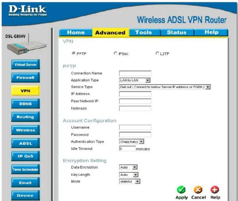
text_image
D-Link Building Networks for People Wireless ADSL VPN Router Home Advanced Tools Status Help VPN ● PPTP ○ IPSec ○ L2TP PPTP Connection Name Application Type LAN to LAN Service Type Dial out ( Connect to below Server IP address or FQDN ) IP Address Peer Network IP Netmask Account Configuration Username Password Authentication Type Cchap(Auto)_ Idle Timeout 0 minutes Encryption Setting Data Encryption Auto Key Length Auto Mode upgrades stateful Apply Cancel Help DSL-G804V Virtual Server Firewall VPN DDNS Routing Wireless ADSL IP QoS Time Schedule Email DeviceFigure 4-12. VPN - PPTP LAN to LAN
| Parameter | Description |
| Connection Name | A user-defined name for the connection (e.g. “connection to office”). |
| Service Type | Check Dial Out if you want your router to operate as a client (connecting to a remote VPN server, e.g. your office server), check Dial In operates as a VPN server by assigning IP address to dial-in user. |
| IP Address | If uses Dial Out as a client to the remote server, enter Server IP Address of the remote server IP address. |
| Peer Network | Enter Peer network IP address. |
| Net Mask | Enter the subnet mask of peer network based on the Peer Network IP setting.If uses Dial In as a server, enter a Private IP Address Assigned to the Dial-in user. |
| AccountConfiguration | |
| Username | If you are a Dial-Out user (client), enter the username provided by your Host.If you are a Dial-In user (server), enter your own username. |
| Password | If you are a Dial-Out user (client), enter the password provided by your Host.If you are a Dial-In user (server), enter your own password. |
| Authentication Type | Default is Auto if you want the router to determine the authentication type to use, or else manually specify CHAP (Challenge Handshake Authentication Protocol) or PAP (Password Authentication Protocol) if you know which type the server is using (when acting as a client), or else the authentication type you want clients connecting to you to use (when acting as a server). When using PAP, the password is sent unencrypted, whilst CHAP encrypts the password before sending, and also allows for challenges at different periods to ensure that the client has not been replaced by an intruder. |
| Idle Timeout (in minutes) | Auto-disconnect the VPN connection when there is no activity on the connection for a predetermined period of time. 0 means this connection is always on. |
| Encryption Setting | |
| Data Encryption | Data sent over the VPN connection can be encrypted by an MPPE algorithm.Default is Auto, so that this setting is negotiated when establishing a connection, or else you can manually Enable or Disable encryption. |
| Key Length | The data can be encrypted by MPPE algorithm with 40 bits or 128 bits. Default is Auto, it is negotiated when establishing a connection. 128 bit keys provide stronger encryption than 40 bit keys. |
| Mode | You may select Stateful or Stateless mode. The key will be changed every 256 packets when you select Stateful mode. If you select Stateless mode, the key will be changed in each packet. |
IPSec (IP Security Protocol)
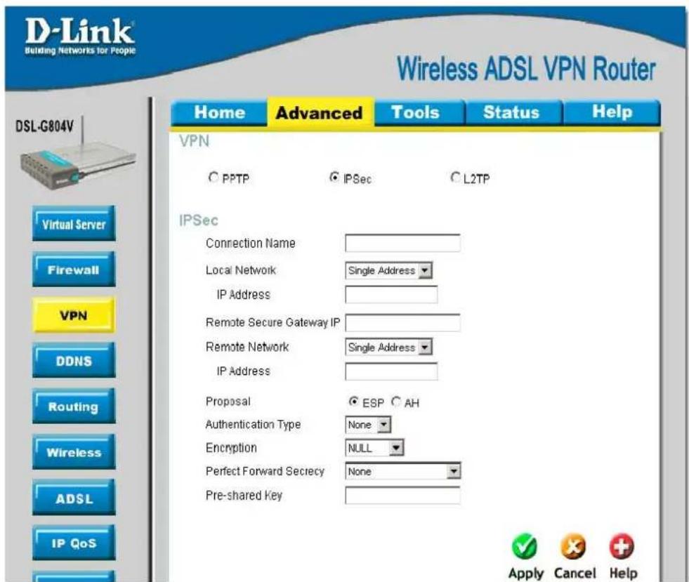
text_image
D-Link Building Networks for People Wireless ADSL VPN Router Home Advanced Tools Status Help VPN C PPTP IPSec L2TP IPSec Connection Name Local Network Single Address IP Address Remote Secure Gateway IP Remote Network Single Address IP Address Proposal ESP AH Authentication Type None Encryption=NULL Perfect Forward Secrecy None Pre-shared Key Virtual Server Firewall VPN DDNS Routing Wireless ADSL IP QoS Apply Cancel Help DSL-G804VFigure 4-13. VPN - IPSec
| Parameter | Description |
| Connection Name | A user-defined name for the connection. No digital number is allowed. |
| Local Network | Set the Single address, subnet or IP range of the local network.IP Address: The IP address of the local host.Netmask: The subnet of the local network. For example, IP: 192.168.0.0 with netmask 255.255.255.0 specifies one class C subnet starting from 192.168.0.1 (i.e. 192.168.1.1 through to 192.168.1.254)End IP: The IP address range of the local network. For example, IP: 192.168.0.1, end IP: 192.168.0.10 |
| Remote Secure Gateway IP | The IP address or hostname of the remote VPN device that is connected and establishes a VPN tunnel. |
| Remote Network | Set the Single address, subnet or IP range of the remote network.IP Address: The IP address of the remote host.Netmask: The subnet of the remote network. For example, IP: 192.168.1.0 with netmask 255.255.255.0 specifies one class C subnet starting from 192.168.1.1 (i.e. 192.168.1.1 through to 192.168.1.254).End IP: The IP address range of the remote network. For example, IP: 192.168.1.1, end IP: 192.168.1.10. |
| Proposal | Select the IPSec security method. There are two methods of checking the authentication information, AH (authentication header) and ESP (Encapsulating Security Payload). Use ESP for greater security so that data will be encrypted and authenticated. Using AH data will be authenticated but not encrypted. |
| Authentication Type | Authentication establishes the integrity of the datagram and ensures it is not tampered with in transmit. There are three options, Message Digest 5 (MD5), Secure Hash Algorithm (SHA1) or NONE. SHA-1 is more resistant to brute-force attacks than MD5, however it is slower. |
| Encryption | Select the encryption method from the pull-down menu. There are several options, DES, 3DES, AES (128, 192 and 256) and NULL. NULL means it is a tunnel only with no encryption. 3DES and AES are more powerful but increase latency. |
| Perfect Forward Secrecy | Choose whether to enable PFS using Diffie-Hellman public-key cryptography to change encryption keys during the second phase of VPN negotiation. This function will provide better security, but extends the VPN negotiation time. Diffie-Hellman is a public-key cryptography protocol that allows two parties to establish a shared secret over an unsecured communication channel (i.e. over the Internet). There are three modes, MODP 768-bit, MODP 1024-bit and MODP 1536-bit. MODP stands for Modular Exponentiation Groups. |
| Pre-shared Key | This is for the Internet Key Exchange (IKE) protocol, a string from 4 to 128 characters. Both sides should use the same key. IKE is used to establish a shared security policy and authenticated keys for services (such as IPSec) that require a key. Before any IPSec traffic can be passed, each router must be able to verify the identity of its peer. This can be done by manually entering the pre-shared key into both sides (router or hosts). |
Click Apply to save the setting.
IPSec - Advanced Option (In the VPN/IPSec List, select a IPSec rule then click the Edit to modify)
This function is only available after completed creating an IPSec account. Click Advanced Option to change the following settings:

text_image
DSL-G804V Home Advanced Tools Status Help IPSec IKE Mode Main IKE Proposal Hash Function SHA1 Encryption 3DES Diffie-Hellman Group MODP 1024 (Group 2) Local ID Type Default Content Remote ID Type Default Identifier SA Lifetime Phase 1 (IKE) 240 minutes Phase 2 (IPSec) 60 minutes PING for keepalive PING to the IP 0.0.0.0 (0.0.0.0 means NEVER) Interval 10 seconds (0-3000, 0 means NEVER) Disconnection Time after no traffic 1200 seconds (180 at least) Reconnection Time 15 minutes (3 at least) Apply Cancel HelpFigure 4-14. VPN - IPSec Advanced Option
| Parameter | Description |
| IKE Mode | Select IKE (Internet Key Exchange) mode to Main mode or Aggressive mode. IKE provides secured key generation and key management. |
| IKE Proposal | |
| Hash Function | It is a Message Digest algorithm which coverts any length of a message into a unique set of bits. It is widely used MD5 (Message Digest) and SHA-1 (Secure Hash Algorithm) algorithms. |
| Encryption | Select the encryption method from the pull-down menu. There are several options, DES, 3DES and AES(128, 192 and 256). 3DES and AES are more powerful but increase latency. |
| Diffie-Hellman Group | It is a public-key cryptography protocol that allows two parties to establish a shared secret over an unsecured communication channel (i.e. over the Internet). There are three modes, MODP 768-bit, MODP 1024-bit and MODP 1536-bit. MODP stands for Modular Exponentiation Groups. |
| Local ID | |
| Type | Specify Local ID type. |
| Content | Input Local ID's information, either email or domain name. |
| Remote ID | |
| Type | Specify Remote ID type. |
| Content | Input remote ID's information, either email or domain name. |
| SA Lifetime | |
| Phase 1 (IKE) | To issue an initial connection request for a new VPN tunnel. The range can be from 5 to 15,000 minutes. |
| Phase 2 (IPSec) | To negotiate and establish secure authentication. The range can be from 5 to 15,000 minutes. |

A short SA time increases security by forcing the two parties to update the keys. However, every time the VPN tunnel re-negotiates, access through the tunnel will be temporarily disconnected.
PING for keepalive
It is used to detect IPSec tunnel connection failure. Connection failure is defined as abort or in NO response state. In such event Ping to Keepalive takes proper action to ensure the connection quality of IPSec.
PING to the IP
It is able to IP Ping the remote PC with the specified IP address and alert when the connection fails. Once alter message is received, Router will drop this tunnel connection. Re-establish of this connection is required. 0.0.0.0 which disables the function.
Interval
This sets the time interval between Pings to the IP function to monitor the connection status. Time interval can be set from 0 to 3600 second, 0 second disables the function.
| Ping to the IP Internal (sec) Ping to the IP Action | ||
| 0.0.0.0 | 0 | No |
| 0.0.0.0 2000 No | ||
| xxx.xxx.xxx.xxx (A valid IP Address) | 0 | No |
| xxx.xxx.xxx.xxx(A valid IP Address) | 2000 Yes, activate it in every 2000 second. | |
Disconnection Time after no traffic
It is the NO Response time clock. When no traffic stage time is beyond the Disconnection time set, Router will automatically halt the tunnel connection and re-establish it base on the Reconnection Time set. 180 seconds is minimum time interval for this function.
Reconnection Time
It is the reconnecting time interval after NO TRAFFIC is initiated. Default setting is 15 minutes; 3 minutes is minimum time interval for this function.
L2TP (Layer2 Tunneling Protocol)
There are two types of L2TP VPN supported: Remote Access and LAN-to-LAN.
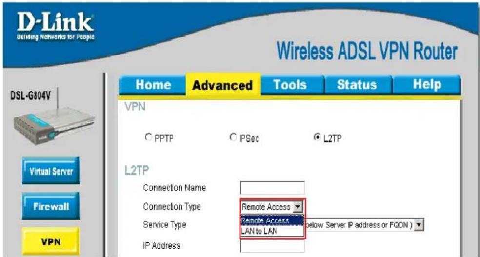
text_image
D-Link Building Networks for People Wireless ADSL VPN Router Home Advanced Tools Status Help VPN C PPTP C IPSec © L2TP Virtual Server Firewall VPN L2TP Connection Name Connection Type Remote Access Service Type Remote Access LAN to LAN below Server IP address or FQDN ) IP AddressFigure 4-15. VPN - L2TP
L2TP - Remote Access

text_image
DSL-G804V Home Advanced Tools Status Help VPN ○ PPTP ○ IPSec ● L2TP Virtual Server Firewall VPN DDNS Routing Wireless ADSL IP QoS Time Schedule Email Device IGMP L2TP Connection Name Connection Type Remote Access Service Type Dial out ( Connect to below Server IP address or FQDN ) IP Address Account Configuration Username Password Authentication Type Chap(Auto) Idle Timeout 0 minutes □ Active as default route □ Enable IPSec Authentication None Encryption NULL Perfect Forward Secrecy None Pre-shared Key □ Enable Tunnel Authentication Secret Remote Host Name (optional) Local Host Name (optional) Apply Cancel HelpFigure 4-16. VPN - L2TP Remote Access
| Parameter | Description |
| Connection Name | A user-defined name for the connection. |
| Service Type | Check Dial Out if you want your router to operate as a client (connecting to a remote VPN server, e.g. your office server), check Dial In operates as a VPN server by assigning IP address to dial-in user. |
| IP Address | If uses Dial Out as a client to the remote server, enter Server IP Address of the remote server IP address.If uses Dial In as a server, enter a Private IP Address Assigned to the Dial-in user. |
| Account Configuration | |
| Username | If you are a Dial-Out user (client), enter the username provided by your Host.If you are a Dial-In user (server), enter your own username. |
| Password | If you are a Dial-Out user (client), enter the password provided by your Host.If you are a Dial-In user (server), enter your own password. |
| Authentication Type | Default is Auto if you want the router to determine the authentication type to use, or else manually specify CHAP (Challenge Handshake Authentication Protocol) or PAP (Password Authentication Protocol) if you know which type the server is using (when acting as a client), or else the authentication type you want clients connecting to you to use (when acting as a server). When using PAP, the password is sent unencrypted, whilst CHAP encrypts the password before sending, and also allows for challenges at different periods to ensure that the client has not been replaced by an intruder. |
| Idle Timeout (in minutes) | Auto-disconnect the VPN connection when there is no activity on the connection for a predetermined period of time. 0 means this connection is always on. |
| Activate as default route | Enables the default route. |
| Enable IPSec | Enable for enhancing your LT2P VPN security. Check the box to active these functions. |
| When Enable IPSec is activated | |
| Authentication | Authentication establishes the integrity of the datagram and ensures it is not tampered with in transmit. There are three options, Message Digest 5 (MD5), Secure Hash Algorithm (SHA1) or NONE. SHA-1 is more resistant to brute-force attacks than MD5, however it is slower. |
| Encryption | Select the encryption method from the pull-down menu. There are several options, DES, 3DES, AES(128, 192 and 256) and NULL. NULL means it is a tunnel only with no encryption. 3DES and AES are more powerful but increase latency. |
| Perfect Forward Secrecy | Choose whether to enable PFS using Diffie-Hellman public-key cryptography to change encryption keys during the second phase of VPN negotiation. This function will provide better security, but extends the VPN negotiation time. Diffie-Hellman is a public-key cryptography protocol that allows two parties to establish a shared secret over an unsecured communication channel (i.e. over the Internet). There are three modes, MODP 768-bit, MODP 1024-bit and MODP 1536-bit. MODP stands for Modular Exponentiation Groups. |
| Pre-shared Key | This is for the Internet Key Exchange (IKE) protocol, a string from 4 to 128 characters. Both sides should use the same key. IKE is used to establish a shared security policy and authenticated keys for services (such as IPSec) that require a key. Before any IPSec traffic can be passed, each router must be able to verify the identity of its peer. This can be done by manually entering the pre-shared key into both sides (router or hosts). |
| When Enable Tunnel Authentication is activated | |
| Secret | The secure password length should be 16 characters which may include numbers and characters. |
| Remote Host Name | (Option) Enter hostname of remote VPN device. It is a tunnel identifier from the Remote VPN device matches with the Remote hostname provided. If remote hostname matches, tunnel will be connected; otherwise, it will be dropped.Cautious: This is only when the router performs as a VPN server. This option should be used by advanced users only. |
| Local Host Name | (Option) Enter hostname of Local VPN device that is connected / establishes a VPN tunnel. As default, Router's default Hostname is home.gateway. |
L2TP - LAN-to-LAN

text_image
DSL-G804V Home Advanced Tools Status Help VPN C PPTP IPSec L2TP L2TP Connection Name Connection Type LAN to LAN Service Type Dial out ( Connect to below Server IP address or FQDN ) IP Address Peer Network IP Netmask Account Configuration Username Password Authentication Type Chap(Auto) Idle Timeout 0 minutes Enable IPSec Authentication None Encryption NULL Perfect Forward Secrecy None Pre-shared Key Enable Tunnel Authentication Secret Remote Host Name (optional) Local Host Name (optional) Apply Cancel HelpFigure 4-17. VPN - L2TP LAN to LAN
| Parameter | Description |
| Connection Name | A user-defined name for the connection (e.g. “connection to office”). |
| Service Type | Check Dial Out if you want your router to operate as a client (connecting to a remote VPN server, e.g. your office server), check Dial In operates as a VPN server by assigning IP address to dial-in user. |
| IP Address | If uses Dial Out as a client to the remote server, enter Server IP Address of the remote server IP address. |
| Peer Network | Enter Peer network IP address. |
| Net Mask | Enter the subnet mask of peer network based on the Peer Network IP setting.If uses Dial In as a server, enter a Private IP Address Assigned to the Dial-in user. |
| AccountConfiguration | |
| Username | If you are a Dial-Out user (client), enter the username provided by your Host.If you are a Dial-In user (server), enter your own username. |
| Password | If you are a Dial-Out user (client), enter the password provided by your Host.If you are a Dial-In user (server), enter your own password. |
| Authentication Type | Default isAutoif you want the router to determine the authentication type to use, or else manually specify CHAP (Challenge Handshake Authentication Protocol) or PAP (Password Authentication Protocol) if you know which type the server is using (when acting as a client), or else the authentication type you want clients connecting to you to use (when acting as a server). When using PAP, the password is sent unencrypted, whilst CHAP encrypts the password before sending, and also allows for challenges at different periods to ensure that the client has not been replaced by an intruder. |
| Idle Timeout (in minutes) | Auto-disconnect the VPN connection when there is no activity on the connection for a predetermined period of time. 0 means this connection is always on. |
| Enable IPSec | Enable for enhancing your LT2P VPN security. Check the box to active these functions. |
| When Enable IPSec is activated | |
| Authentication | Authentication establishes the integrity of the datagram and ensures it is not tampered with in transmit. There are three options, Message Digest 5 (MD5), Secure Hash Algorithm (SHA1) orNONE. SHA-1 is more resistant to brute-force attacks than MD5, however it is slower. |
| Encryption | Select the encryption method from the pull-down menu. There are several options, DES, 3DES, AES(128, 192 and 256) and NULL. NULL means it is a tunnel only with no encryption. 3DES and AES are more powerful but increase latency. |
| Perfect Forward Secrecy | Choose whether to enable PFS using Diffie-Hellman public-key cryptography to change encryption keys during the second phase of VPN negotiation. This function will provide better security, but extends the VPN negotiation time. Diffie-Hellman is a public-key cryptography protocol that allows two parties to establish a shared secret over an unsecured communication channel (i.e. over the Internet). There are three modes, MODP 768-bit, MODP 1024-bit and MODP 1536-bit. MODP stands for Modular Exponentiation Groups. |
| Pre-shared Key | This is for the Internet Key Exchange (IKE) protocol, a string from 4 to 128 characters. Both sides should use the same key. IKE is used to establish a shared security policy and authenticated keys for services (such as IPSec) that require a key. Before any IPSec traffic can be passed, each router must be able to verify the identity of its peer. This can be done by manually entering the pre-shared key into both sides (router or hosts). |
| When Enable Tunnel | |
| Authentication is activated | |
| Secret | The secure password length should be 16 characters which may include numbers and characters. |
| Remote Host Name | (Option) Enter hostname of remote VPN device. It is a tunnel identifier from the Remote VPN device matches with the Remote hostname provided. If remote hostname matches, tunnel will be connected; otherwise, it will be dropped.Cautious: This is only when the router performs as a VPN server. This option should be used by advanced users only. |
| Local Host Name | (Option) Enter hostname of Local VPN device that is connected / establishes a VPN tunnel. As default, Router's default Hostname ishome.gateway. |
DDNS (Dynamic DNS)
The Dynamic DNS function allows you to alias a dynamic IP address to a static hostname, allowing users whose ISP does not assign them a static IP address to use a domain name. This is especially useful for hosting servers via your ADSL connection, so that anyone wishing to connect to you may use your domain name, rather than having to use your dynamic IP address, which changes from time to time. This dynamic IP address is the WAN IP address of the router, which is assigned to you by your ISP.
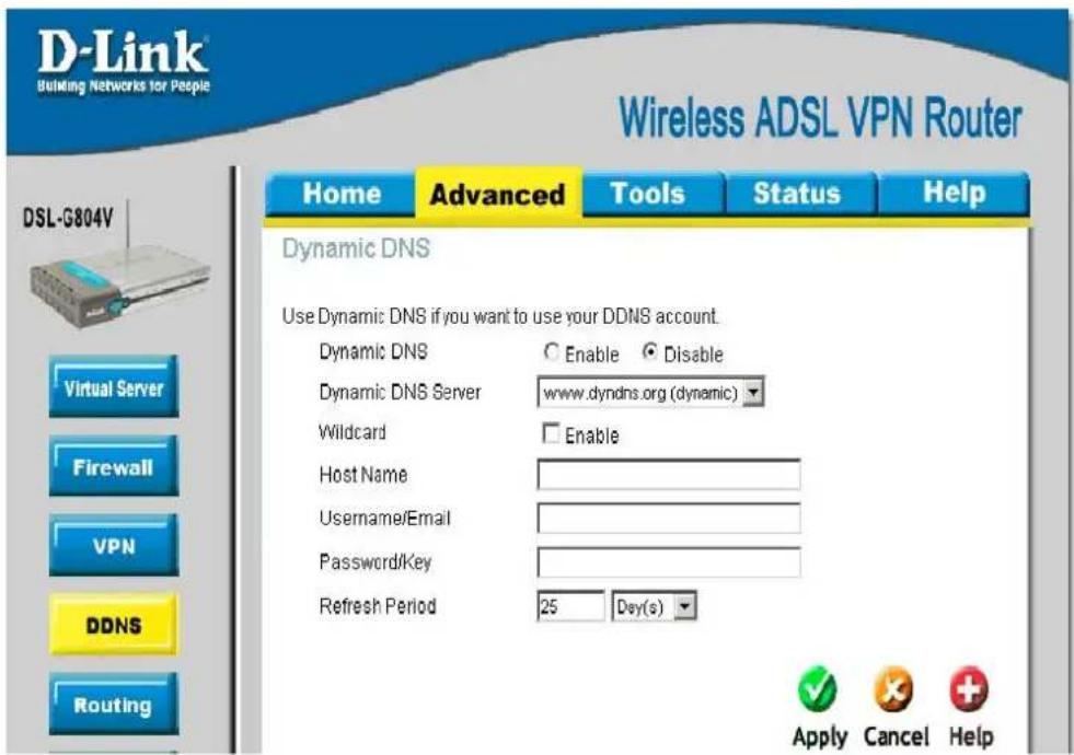
text_image
D-Link Building Networks for People Wireless ADSL VPN Router Home Advanced Tools Status Help Dynamic DNS Use Dynamic DNS if you want to use your DDNS account. Dynamic DNS Enable Disable Dynamic DNS Server www.dyndns.org (dynamic) Wildcard Enable Host Name Username/Email Password/Key Refresh Period 25 Day(s) Apply Cancel Help DSL-G804V Virtual Server Firewall VPN DDNS RoutingFigure 4-18. DDNS
| Parameter | Description |
| Dynamic DNS | Disable or activate this feature. |
| Dynamic DNS Server | Select the DDNS service you have established an account with. |
| Wildcard | When wildcard is enabled, a multiple matching to the Host Name will be point to the same IP. Example: You have a host abce.no-ip.com. When the wildcard enabled, xxxxx.abce.no-ip.com would point to the same IP address as your abce.no-ip.com. |
| Host Name,Username/Email and Password/Key | Enter your registered domain name and your username and password for this service. |
| Reflash Period | Set the time period between updates, for the Router to exchange information with the DDNS server. In addition to updating periodically as per your settings, the router will perform an update when your dynamic IP address changes. |
Routing (Static Route)
Manually adds a static route to router routing table.
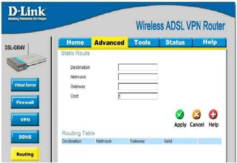
text_image
D-Link Building Networks for People Wireless ADSL VPN Router Home Advanced Tools Status Help Static Route Destination Netmask Gateway Cost 1 Routing Table Destination Netmask Gateway Vaild Apply Cancel HelpFigure 4-19. Routing (Static Route)
| Parameter | Description |
| Destination | This is the destination subnet IP address. |
| Netmask | Subnet mask of the destination IP addresses based on above destination subnet IP. |
| Gateway | This is the gateway IP address to which packets are to be forwarded. |
| Interface | Select the interface through which packets are to be forwarded. |
| Cost | This is the same meaning as Hop. This should usually be left at 1. |
Wireless
Wireless Security and Wireless Client Filter parameter setup.
Wireless Security
The default mode of your wireless (access point) security is inactivated. You may choose either WPA or WEP to protect your wireless network.
Wireless Security – WPA Pre-Shared Key
WPA Algorithms utilize the TKIP (Temporal Key Integrity Protocol), a stronger encryption method and incorporates Message Code (MIC), to protect against hackers and security your wireless network.

text_image
D-Link Building Networks for People Wireless ADSL VPN Router Home Advanced Tools Status Help DSL-G804V Virtual Server Firewall VPN DDNS Routing Wireless Wireless Security Wireless Client Filter Wireless security These are the wireless settings for the AP(Access Point) portion. Security Mode WPA Pre-Shared Key WPA Algorithms TKIP WPA Shared Key Group Key Renewal 600 seconds Idle Timeout 3600 seconds (120~65535) Apply Cancel HelpFigure 4-20. Wireless Security – WPA Pre-Shared Key
| Parameter | Description |
| WPA Shared Key | The key for network authentication. The input format is in character style and key size should be in the range between 8 and 63 characters. |
| Group Key Renewal (in seconds) | The period of renewal time for changing the security key automatically between wireless client and Access Point (AP) |
| Idle Timeout (in seconds) | A Timeout value base on the case of no data traffic is send or received. If Router detects no traffic in the wireless, it will start timing the clock and drop the session as it reaches to the defined timeout value. New session will be re-established after the old session. Minimum value is 120 seconds to Maximum 65535 seconds. |
Wireless Security – WEP
A WEP encryption algorithm is defined by a set of respective Key and Key String for the wireless network.

text_image
D-Link Building Networks for People Wireless ADSL VPN Router Home Advanced Tools Status Help DSL-G804V Virtual Server Firewall VPN DDNS Routing Wireless ADSL IP QoS Wireless ● Wireless Security ○ Wireless Client Filter Wireless security These are the wireless settings for the AP(Access Point) portion. Security Mode WEP WEP Authentication Open System WEP Encryption ● WEP64 ○ WEP128 Hex Default Used WEP Key 0 (0~3) Key 0 00-00-00-00-00 Key 1 00-00-00-00-00 Key 2 00-00-00-00-00 Key 3 00-00-00-00-00 Apply Cancel HelpFigure 4-20. Wireless Security – WEP
| Parameter | Description |
| WEP Authentication | Three types of authentication are available,Open System, Shared Key and Open System/ShareKey (Both).Open System:Authentication is a void authentication; it is easy to use. As long as the wireless client uses the same WEP key will be able to communicate with router's Access Point. The AP will remain visible to all devices on the network.Share Key:It is more secure than the Open System. Wireless client must use the same authentication and the Web Key to be able to communicate with router's Access Point.Open System / Share Key (Both):With this setting both open and share key are employed. Wireless client may have selected open or share key setting and still can get access to the Access point, only if correct WEP Key is presented. |
| WEP Encryption | To prevent unauthorized wireless stations from accessing data transmitted over the network, the router offers highly secure data encryption, known as WEP. If you require high security for transmissions, there are two alternatives to select from:WEP 64 and WEP 128. WEP 128 will offer increased security over WEP 64. |
| Default Used WEP Key (0-3) | Enter the key to encrypt wireless data. To allow encrypted data transmission, the WEP Encryption Key values on all wireless stations must be the same as the router. There are four keys for your selection. The input format is in HEX style, 5 and 13 HEX codes are required for WEP64 and WEP128 respectively, the separator is “-”. For example, using WEP64, 11-22-33-44-55 is a valid key, whilst 1122334455 is invalid. |
Wireless Client (MAC) Filter
The MAC Address supports up to 16 wireless network machines and helps you to manage your network control to accept traffic from specific authorized machines or to restrict unwanted machine(s) to access your Wireless LAN.
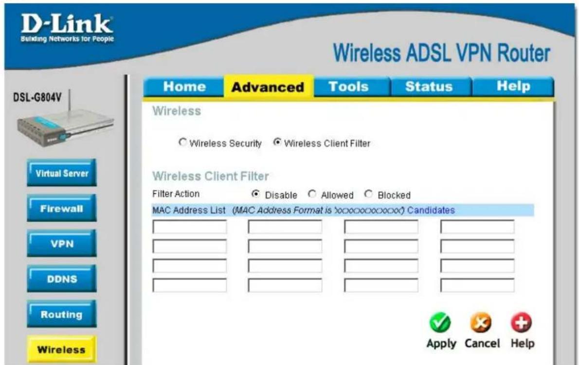
text_image
D-Link Building Networks for People Wireless ADSL VPN Router Home Advanced Tools Status Help DSL-G804V Wireless ○ Wireless Security ● Wireless Client Filter Wireless Client Filter Filter Action ○ Disable ○ Allowed ○ Blocked MAC Address List (MAC Address Format is 'xxxxxxxxxxxx' Candidates Apply Cancel HelpFigure 4-20. Wireless Client (MAC) Filter
| Parameter | Description |
| Filter Action | Select an appreciated filter action, Disable, Allowed (Whitelist), and Blocked (Blacklist):Disabled: This inactivates the Wireless Client Filter function. Allowed (White List): This authorizes specific device accessing your wireless by insert the wireless AP MAC Address in the space provided. Make sure you wireless AP MAC is listed. Blocked (Blacklist): check to prevent unwanted device accessing your wireless by insert the wireless AP MAC Address in the space provided. Make sure your wireless AP MAC is NOT listed. Candidates: Associated Wireless Clients displays a list of individual Wireless AP MAC address which connecting to the router. You can easily by checking the box next to the IP address to be blocked or allowed. Then Add to insert to the Wireless Client Filter table. The maximum Wireless client is 16. |
ADSL
This is the ADSL parameter adjustment and information section. The parameter is already being pre-defined and not necessary to reconfigure if you do not understand this feature.

text_image
D-Link Building Networks for People Wireless ADSL VPN Router Home Advanced Tools Status Help DSL-G804V Virtual Server Firewall VPN DDNS Routing Wireless ADSL ADSL ConnectMode AnnexA Modulation Multimode Activate Line(true Coding Gain auto Tx Attenuation Dmt_ODB DSP Firmware Version D.57.5.2 Connected Protein false Operational Mode Inactive Annex Type AnnexA Upstream Bit Rate 0 Downstream Bit Rate 0 Apply Cancel HelpFigure 4-23. ADSL
| Parameter | Description |
| Connect Mode | Connection line mode ADSL2/ADSL2+. |
| Modulation | For ADSL connection, this mode will automatically detect your ADSL line code, G.dmt, G.lite, and T1.413. But in some area, multimode cannot detect the ADSL line code well. If it is the case, please adjust the ADSL line code to G.dmt or T1.413 first. If it still fails, please try the other values such as ALCTL, ADI, etc. For ADSL2 connection, this mode automatically detects your line code to G.DMT.Bis. |
| Activate Line | Aborting (false) your ADSL line and making it active (true) again for taking effect with setting of Connect Mode. |
| Coding Gain | Configure the ADSL coding gain from 0 dB to 7dB, or automatic. |
| Tx Attenuation | Setting ADSL transmission attenuation. |
| DSP Firmware Version | Firmware version of the Digital Signal Processor. |
| Connected Operational Mode | Display current ADSL line sync status. |
| Annex Type | ADSL Annex A, which works over a standard telephone line. Annex B, which works over an ISDN line. |
| Upstream Bit Rate | Display current upstream rate of your ADSL line. |
| Downstream Bit Rate | Display current downstream rate of your ADSL line. |
IP QoS
IP QoS function helps you to control your network traffic for each application from LAN (Ethernet and/or Wireless) to WAN (Internet). It facilitates you to control the different quality and speed of through put for each application when the system is running with full loading of upstream.
You can find three items under the QoS section: Prioritization and Outbound / Inbound IP Throttling (bandwidth management).
Packet Prioritization
Prioritization categorizes in High (utilized 60% of the total bandwidth), Normal (utilized 30% of the total bandwidth), Low (utilized 10% of the total bandwidth).
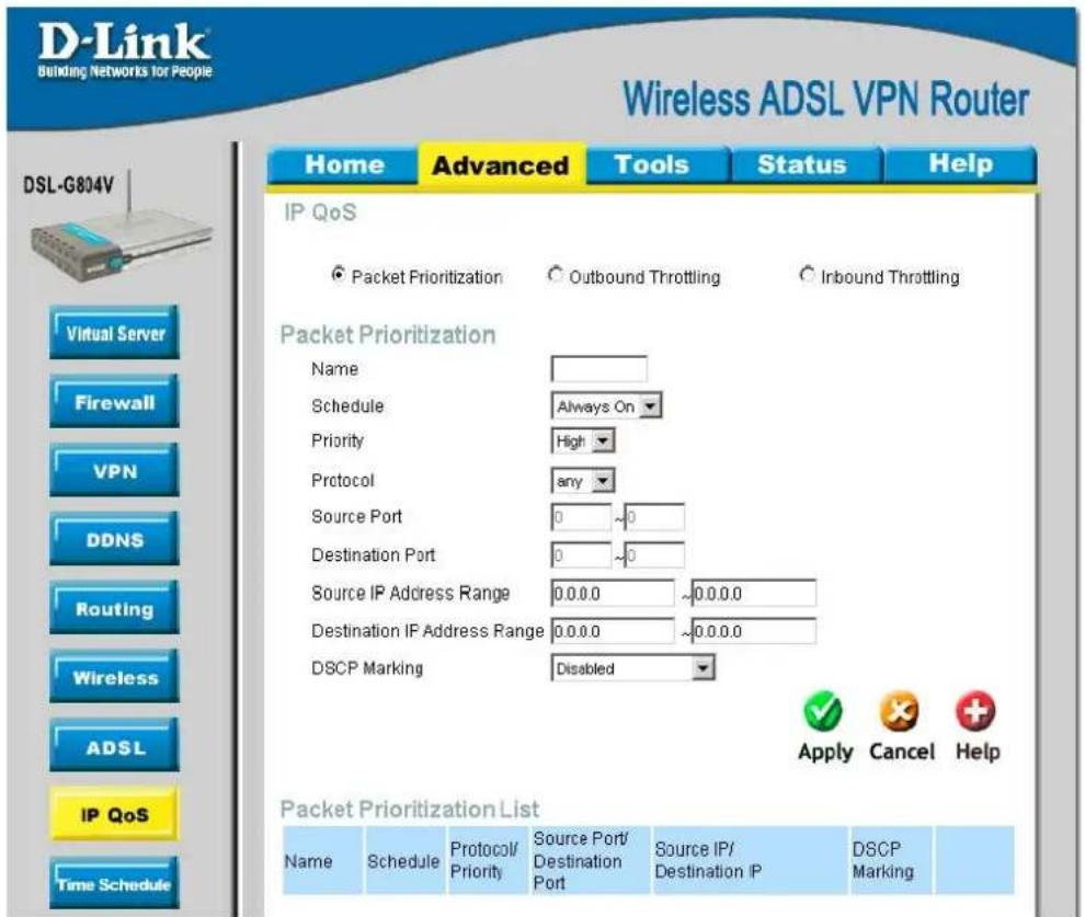
text_image
D-Link Building Networks for People Wireless ADSL VPN Router Home Advanced Tools Status Help IP QoS Packet Prioritization Packet Prioritization Name Schedule Always On Priority High Protocol any Source Port 0 ~0 Destination Port 0 ~0 Source IP Address Range 0.0.0.0 ~0.0.0.0 Destination IP Address Range 0.0.0.0 ~0.0.0.0 DSCP Marking Disabled Apply Cancel Help Packet Prioritization List Name Schedule Protocol/ Priority Source Port/ Destination Port Source IP/ Destination IP DSCP Marking DSL-G804V Virtual Server Firewall VPN DDNS Routing Wireless ADSL IP QoS Time ScheduleFigure 4-24. IP QoS – Packet Prioritization
| Parameter | Description |
| Name | A user-defined description to identify this new policy/application. |
| Schedule | Check Disable radio button to inactivate the URL Filtering function, or keep the URL Filtering as Always on. You may also specify a time schedule for your prioritization policy. For setup and detail, refer to Time Schedule section. |
| Priority | The priority given to each policy/application. Its default setting is set to High; you may adjust this setting to fit your policy/application. |
| Protocol | The name of supported protocol. |
| Source Port | The source port of packets to be monitored. |
| Destination Port | The destination port of packets to be monitored. |
| Source IP Address Range | The source IP address or range of packets to be monitored. |
| Destination IP Address Range | The destination IP address or range of packets to be monitored. |
| DSCP Marking | Differentiated Services Code Point (DSCP), it is the first 6 bits in the ToS byte. DSCP Marking allows users to classify traffic based on DSCP value and send packets to next Router. |
DSCP Mapping Table
| DSCP Mapping Table | |
| (Wireless) ADSL Router Standard DSCP | |
| Disabled None | |
| Best Effort Best Effort (000000) | |
| Premium Express Forwarding (101110) | |
| Gold service (L) Class 1, Gold (001010) | |
| Gold service (M) Class 1, Silver (001100) | |
| Gold service (H) Class 1, Bronze (001110) | |
| Silver service (L) Class 2, Gold (010010) | |
| Silver service (M) Class 2, Silver (010100) | |
| Silver service (H) Class 2, Bronze (010110) | |
| Bronze service (L) Class 3, Gold (011010) | |
| Bronze service (M) Class 3, Silver (011100) | |
| Bronze service (H) Class 3, Bronze (011110) | |
Outbound Throttling (Packet from LAN to WAN)
IP Outbound Throttling allows you to limit the speed of IP traffic. The value entered will limit the speed of the application that you set to the specified value's multiple of 32kbps.
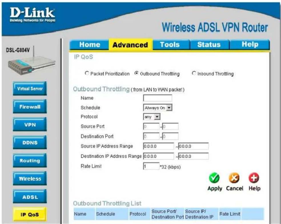
text_image
D-Link Building Networks for People Wireless ADSL VPN Router Home Advanced Tools Status Help IP QoS Packet Prioritization Outbound Throttling Inbound Throttling Outbound Throttling (from LAN to WAN packet) Name Schedule Always On Protocol any Source Port 0 ~0 Destination Port 0 ~0 Source IP Address Range 0.0.0.0 ~0.0.0.0 Destination IP Address Range 0.0.0.0 ~0.0.0.0 Rate Limit 1 *32 (kbps) Apply Cancel Help Outbound Throttling List Name Schedule Protocol Source Port/Source IP/ Destination Port Destination IP Rate Limit DSL-G804V Virtual Server Firewall VPN DDNS Routing Wireless ADSL IP QoSFigure 4-25. IP QoS - Outbound Throttling
| Parameter | Description |
| Name | A user-defined description to identify this new policy/application. |
| Schedule | Check Disable radio button to inactivate the URL Filtering function, or keep the URL Filtering as Always on. You may also specify a time schedule for your prioritization policy. For setup and detail, refer to Time Schedule section. |
| Protocol | The name of supported protocol. |
| Source Port | The source port of packets to be monitored. |
| Destination Port | The destination port of packets to be monitored. |
| Source IP Address Range | The source IP address or range of packets to be monitored. |
| Destination IP Address Range | The destination IP address or range of packets to be monitored. |
| Rate Limit | The limited speed of outbound traffic. |
Inbound Throttling (Packet from WAN to LAN)
IP Inbound Throttling allows you to limit the speed of IP traffic. The value entered will limit the speed of the application that you set to the specified value's multiple of 32kbps.
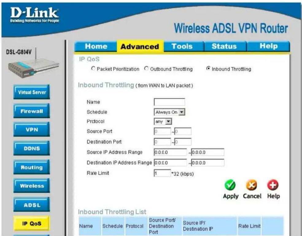
text_image
D-Link Building Networks for People Wireless ADSL VPN Router Home Advanced Tools Status Help IP QoS Packet Prioritization Outbound Throttling Inbound Throttling Virtual Server Firewall VPN DDNS Routing Wireless ADSL IP QoS Inbound Throttling (from WAN to LAN packet) Name Schedule Always On Protocol any Source Port 0 ~0 Destination Port 0 ~0 Source IP Address Range 0.0.0.0 ~0.0.0.0 Destination IP Address Range 0.0.0.0 ~0.0.0.0 Rate Limit 1 *32 (kbps) Apply Cancel Help Inbound Throttling List Name Schedule Protocol Sompou Port Destination Port Source IP/ destination IP Rate LimitFigure 4-26. IP QoS - Inbound Throttling
| Parameter | Description |
| Name | A user-defined description to identify this new policy/application. |
| Schedule | Check Disable radio button to inactivate the URL Filtering function, or keep the URL Filtering as Always on. You may also specify a time schedule for your prioritization policy. For setup and detail, refer to Time Schedule section. |
| Protocol | The name of supported protocol. |
| Source Port | The source port of packets to be monitored. |
| Destination Port | The destination port of packets to be monitored. |
| Source IP Address Range | The source IP address or range of packets to be monitored. |
| Destination IP Address Range | The destination IP address or range of packets to be monitored. |
| Rate Limit | The limited speed of inbound traffic. |
Time Schedule
The Time Schedule supports up to 16 time slots which helps you to manage your Internet connection. It correlates closely with router's time, since router does not have a real time clock on board; it uses the Simple Network Time Protocol (SNTP) to get the current time from an SNTP server from the Internet. Refer to Time Zone for details. You router time should correspond with your local time. If the time is not set correctly, your Time Schedule will not function properly.
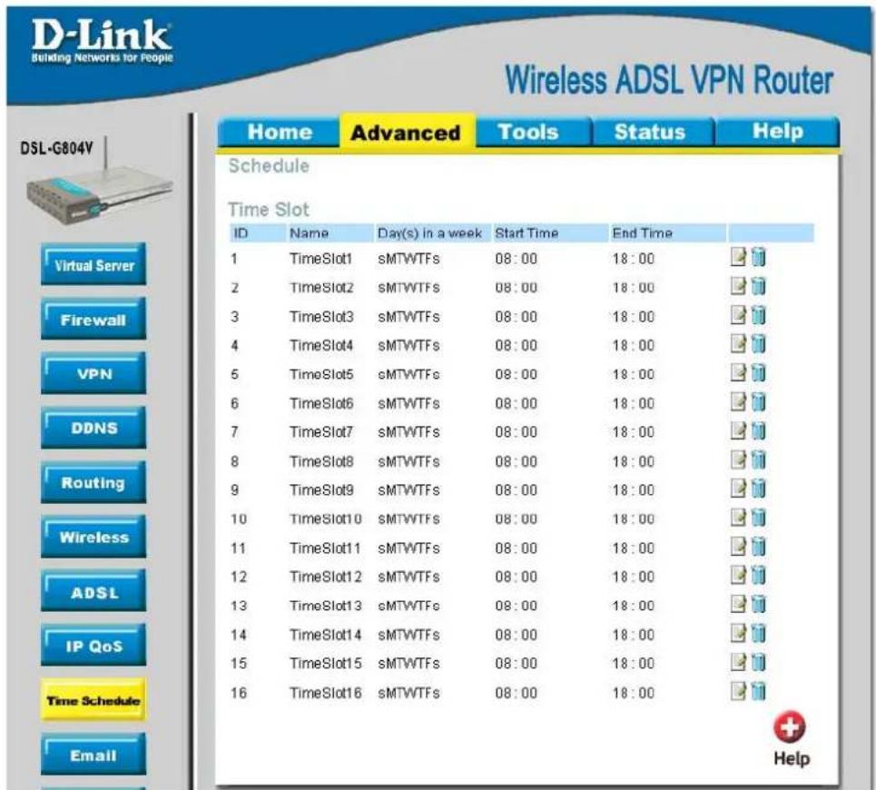
text_image
D-Link® Building Networks for People Wireless ADSL VPN Router Home Advanced Tools Status Help Schedule Time Slot ID Name Day(s) in a week Start Time End Time 1 TimeSlot1 sMTWTFs 08:00 18:00 2_TIMESlot2 sMTWTFs 08:00 18:00 3_TIMESlot3 sMTWTFs 08:00 18:00 4_TIMESlot4 sMTWTFs 08:00 18:00 5_TIMESlot5 sMTWTFs 08:00 18:00 6_TIMESlot6 sMTWTFs 08:00 18:00 7_TIMESlot7 sMTWTFs 08:00 18:00 8_TIMESlot8 sMTWTFs 08:00 18:00 9_TIMESlot9 sMTWTFs 08:00 18:00 10_TIMESlot10 sMTWTFs 08:00 18:00 11_TIMESlot11 sMTWTFs 08:00 18:00 12_TIMESlot12 sMTWTFs 08:00 18:00 13_TIMESlot13 sMTWTFs 08:00 18:00 14_TIMESlot14 sMTWTFs 08:00 18:00 15_TIMESlot15 sMTWTFs 08:00 18:00 16_TIMESlot16 sMTWTFs 08:00 18:00 Virtual Server Firewall VPN DDNS Routing Wireless ADSL IP QoS Time Schedule Email + HelpFigure 4-27. Time Schedule
Adding a Time Slot
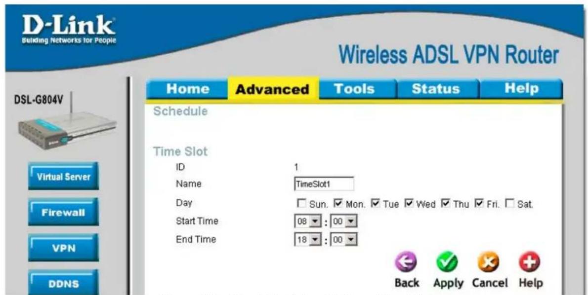
text_image
D-Link Building Networks for People Wireless ADSL VPN Router Home Advanced Tools Status Help Schedule Time Slot ID 1 Name TimeSlot1 Day Sun Mon Tue Wed Thu Fri Sat Start Time 08 : 00 End Time 18 : 00 Back Apply Cancel Help DSL-G804V Virtual Server Firewall VPN DDNSFigure 4-28. Time Schedule – Adding a Time Slot
| Parameter | Description |
| ID | This is the index of the time slot. |
| Name | A user-define description to identify this time portfolio. |
| Day | The default is set from Monday through Friday. You may specify the days for the schedule to be applied. |
| Start Time | The default is set at 8:00 AM. You may specify the start time of the schedule. |
| End Time | The default is set at 18:00 (6:00PM). You may specify the end time of the schedule. |
| Delete a Time Slot | |
| Click Clear to delete the existing Time profile, i.e. erase the Day and back to default setting of Start Time / End Time. | |
Check Email
Check Email allows you to have the router checks your POP3 mailbox for new Email messages. The Mail LED on your router will light when it detects new messages waiting for download. You may also view the status of this function using the Status – Email Checking section of the web interface, which also provides details on the number of new messages waiting. See the Status section of this manual for more information.
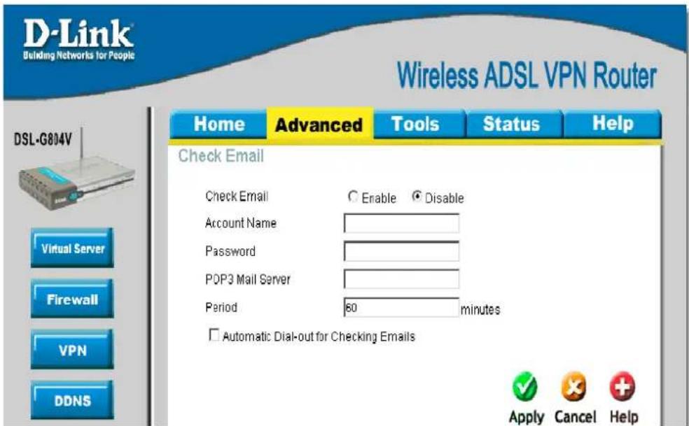
text_image
D-Link Building Networks for People Wireless ADSL VPN Router Home Advanced Tools Status Help Check Email Check Email Enable Disable Account Name Password POP3 Mail Server Period 60 minutes Automatic Dial-out for Checking Emails Apply Cancel Help DSL-G804V Virtual Server Firewall VPN DDNSFigure 4-29. Check Email
| Parameter | Description |
| Check Email | Disable or activate the Email Checking function. |
| Account Name | Enter the name (login) of the POP3 account you wish to check. Normally, it is the text in your email address before the “@” symbol. If you have trouble with it, please contact your ISP (Internet Service Provider). |
| Password | Enter the account's password. |
| POP3 Mail Server | Enter your (POP) mail server name. Your ISP or network administrator will be able to supply you with this. |
| Period (minutes) | Set up a time interval to check your mail. |
| Automatically | When the function is enabled, your ADSL router will connect to your ISP automatically to check your emails if the Internet connection dropped. If your ADSL service is charged by time online, you ought to be careful when using this feature. |
Device Management
The Device Management advanced configuration settings allow you to control your router's security options and device monitoring features.
Device Host Name
This is a given name to your router easily identify the router.
Embedded Web Server
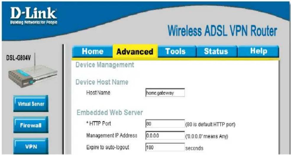
text_image
D-Link Building Networks for People Wireless ADSL VPN Router DSL-G804V Home Advanced Tools Status Help Device Management Device Host Name Host Name home.gateway Embedded Web Server * HTTP Port 80 (80 is default HTTP port) Management IP Address 0.0.0.0 ('0.0.0.0' means Any) Expire to auto-logout 180 secondsFigure 4-30. Device Management – Host Name and Embedded Web Server
| Parameter | Description |
| HTTP Port | This is the port number the router's embedded web server (for web-based configuration) will use. The default value is the standard HTTP port, 80. Users may specify an alternative if, for example, they are running a web server on a PC within their LAN. (Important: This setting will become effective after you Save to flash and restart the router). |
| Management IP Address | You may specify an IP address allowed to logon and access the router's web server. Setting the IP address to 0.0.0.0 will disable IP address restrictions, allowing users to login from any IP address. |
| Expire to auto-logout | Specify a time frame for the system to auto-logout the user's configuration session. |
Example:
User A changes HTTP port number to 100, specifies their own IP address of 192.168.0.55, and sets the logout time to be 100 seconds. The router will only allow User A access from the IP address 192.168.0.55 to logon to the Web GUI by typing: http://192.168.0.1:55 in their web browser. After 100 seconds, the device will automatically logout User A. (192.168.0.1 is your router IP address).
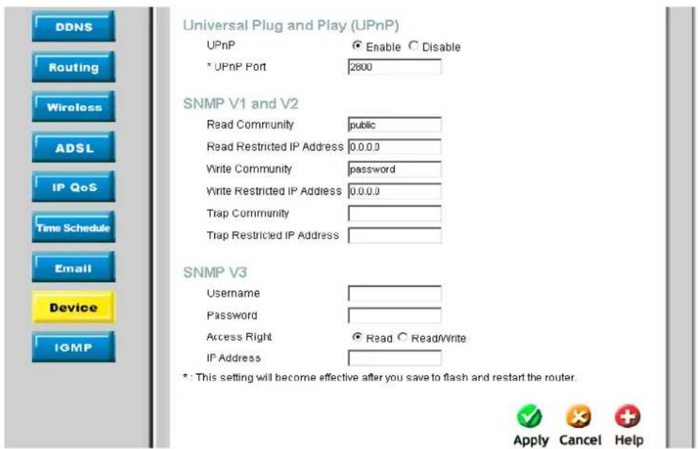
text_image
DDNS Routing Wireless ADSL IP QoS Time Schedule Email Device IGMP Universal Plug and Play (UPnP) UPnP Enable Disable * UPnP Port 2800 SNMP V1 and V2 Read Community public Read Restricted IP Address 0.0.0.0 Write Community password Write Restricted IP Address 0.0.0.0 Trap Community Trap Restricted IP Address SNMP V3 Username Password Access Right Read Write IP Address *: This setting will become effective after you save to flash and restart the router. Apply Cancel HelpFigure 4-31. Device Management – UPnP, SNMP V1 and V2, and SNMP V3
Universal Plug and Play (UPnP)
UPnP offers peer-to-peer network connectivity for PCs and other network devices, along with control and data transfer between devices. UPnP offers many advantages for users running NAT routers through UPnP NAT Traversal, and on supported systems makes tasks such as port forwarding much easier by letting the application control the required settings, removing the need for the user to control advanced configuration of their device.
| Parameter | Description |
| UPnP | Disable or activate the router's UPnP functionality. |
| UPnP Port | Its default setting is 2800. It is highly recommended for users to use this port value. If this value conflicts with other ports already being used you may wish to change the port. (Important: This setting will become effective after you Save to flash and restart the router). |
SNMP V1 and V2 (Simple Network Management Protocol Version 1 and Version 2)
| Parameter | Description |
| Read Community | Specify a name to be identified as the Read Community, and an IP address. This community string will be checked against the string entered in the configuration file. Once the string name is matched, user obtains this IP address will be able to view the data. |
| Write Community | Specify a name to be identified as the Write Community, and an IP address. This community string will be checked against the string entered in the configuration file. Once the string name is matched, users from this IP address will be able to view and modify the data. |
| Trap Community | Specify a name to be identified as the Trap Community, and an IP address. This community string will be checked against the string entered in the configuration file. Once the string name is matched, users from this IP address will be sent SNMP Traps. |
SNMP V3 (Simple Network Management Protocol Version 3)
Specify a name and password for authentication. And define the access right from identified IP address. Once the authentication has succeeded, users from this IP address will be able to view and modify the data.
IGMP
IGMP, known as Internet Group Management Protocol, is used to management hosts from multicast group.
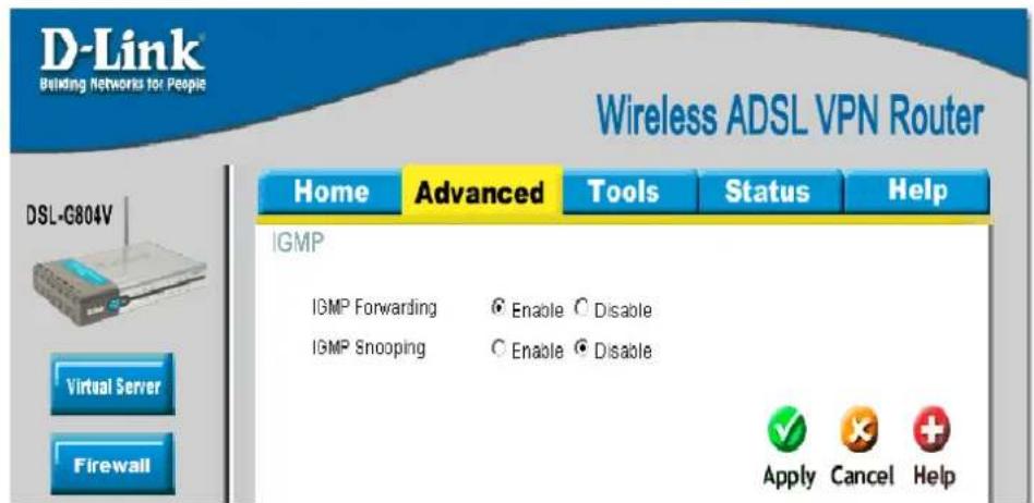
text_image
D-Link Building Networks for People Wireless ADSL VPN Router Home Advanced Tools Status Help DSL-C804V Virtual Server Firewall IGMP IGMP Forwarding Enable Disable IGMP Snooping Enable Disable Apply Cancel HelpFigure 4-32. IGMP
| Para meter | Description |
| IGMP Forwarding | Accepting multicast packet. Default is set to Enable. |
| IGMP Snooping | Allowing switched Ethernet to check and make correct forwarding decisions. Default is set to Disable. |

Tools
Click the Tools tab to access menus used to configure Admin, Data & Time, System, Firmware, Remote Access, Reboot, Save Config and Logout.
Admin - Current Defined Users
You can change the user's password, whether their account is active and Valid, as well as add a comment to each user account. These options are the same when creating a user account, with the exception that once created you cannot change the username. You cannot delete the default admin account; however, you can delete any other created accounts by clicking Delete when editing the user.

text_image
D-Link Building Networks for People Wireless ADSL VPN Router Home Advanced Tools Status Help Current Defined Users Username New Password Reconfirm Password Valid false Comment Apply Cancel Help Valid User Comment true admin Default admin userFigure 5-1. Admin – Current Defined Users
System Date & Time
The router does not have a real time clock on board. You may either select Enable NTP or Set Device Date and Time manually. Enable NTP uses the Simple Network Time Protocol (SNTP) to get the current time from an SNTP server outside your network. Also, You can choose Time Zone List by City or By Time Difference. After a successful connection to the Internet, the router will retrieve the correct local time from the SNTP server you have specified.
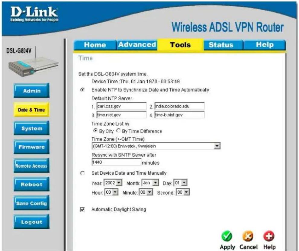
text_image
D-Link Building Networks for People Wireless ADSL VPN Router Home Advanced Tools Status Help DSL-G804V Admin Date & Time System Firmware Remote Access Reboot Save Config Logout Time Set the DSL-G804V system time. Device Time :Thu, 01 Jan 1970 - 00:53:49 Enable NTP to Synchronize Date and Time Automatically Default NTP Server 1. carl.css.gov 2. inda.colorado.edu 3. time.nist.gov 4. time-b.nist.gov Time Zone List by By City By Time Difference Time Zone (+GMT Time) (GMT-12:00) Eniwetok, Kwajalein Resync with SNTP Server after 1440 minutes Set Device Date and Time Manually Year: 2002 Month: Jan Day: 01 Hour: 00 Minute: 00 Second: 00 Automatic Daylight Saving Apply Cancel HelpFigure 5-2. Date & Time
Resync Period (in minutes) is the periodic interval the router will wait before it re-synchronizes the router's time with that of the specified SNTP server. In order to avoid unnecessarily increasing the load on your specified SNTP server you should keep the poll interval as high as possible – at the absolute minimum every few hours or even days.
Daylight Saving is also known as Summer Time Period. Many places in the world adapt it during summer time to move one hour of daylight from morning to the evening in local standard time. Check Automatic Daylight Saving box to auto set your local time.
System Settings
System Setting allows you to save and backup your router's current settings to a file on your PC, or to restore a previously saved backup. This is useful if you wish to experiment with different settings, knowing that you have a backup handy in the case of any mistakes. It is advisable to backup your router's settings before making any significant changes to your router's configuration.
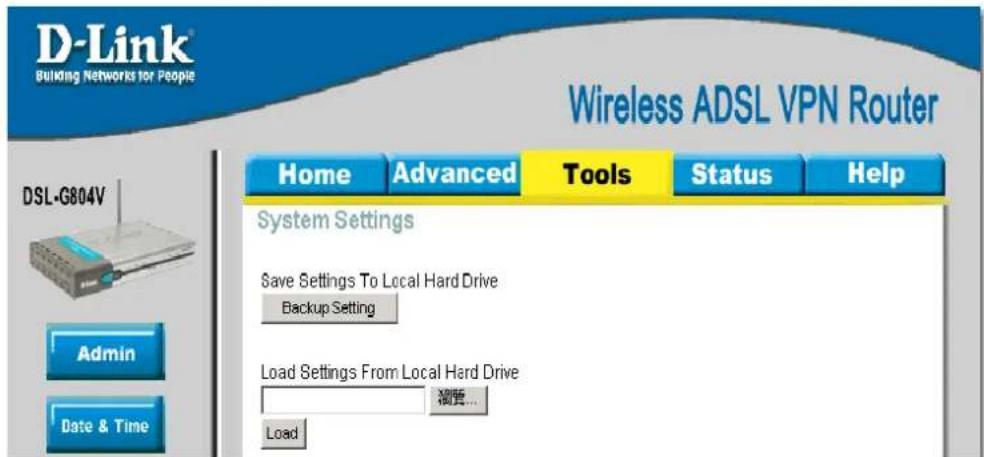
text_image
D-Link Building Networks for People Wireless ADSL VPN Router Home Advanced Tools Status Help DSL-G804V Admin Date & Time System Settings Save Settings To Local Hard Drive Backup Setting Load Settings From Local Hard Drive 摘要... LoadFigure 5-3. System Settings
Press Backup Setting to select where on your local PC to save the settings file. You may also change the name of the file when saving if you wish to keep multiple backups.
Load Setting From Local Hard Drive: Press Browse to select a file from your PC to restore. You should only restore settings files that have been generated by the Backup function, and that were created when using the current version of the router's firmware. Settings files saved to your PC should not be manually edited in any way.
Firmware Upgrade
Your router's "firmware" is the software that allows it to operate and provides all its functionality. Over time this software may be improved and modified, and your router allows you to upgrade the software it runs to take advantage of these changes.
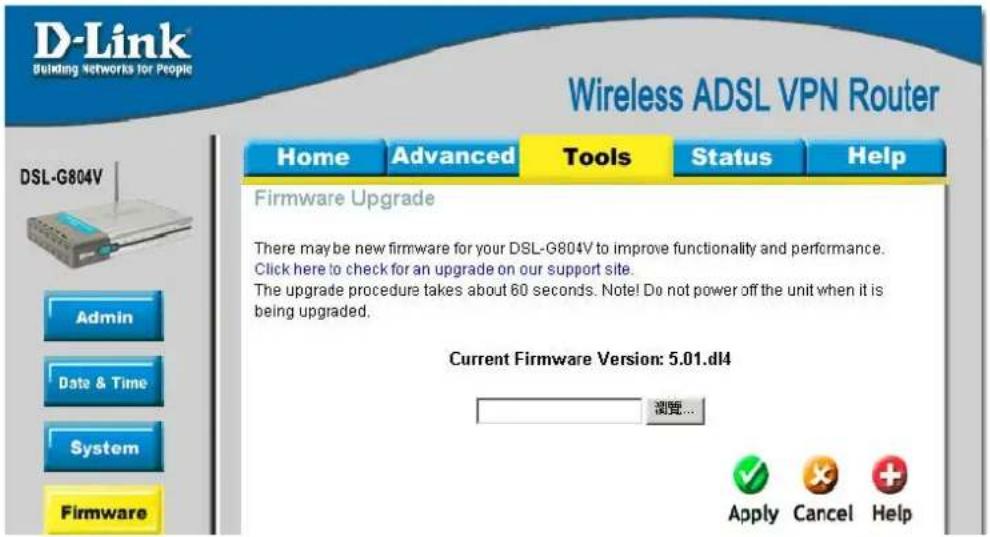
text_image
D-Link Building Networks for People Wireless ADSL VPN Router Home Advanced Tools Status Help Firmware Upgrade There may be new firmware for your DSL-G804V to improve functionality and performance. Click here to check for an upgrade on our support site. The upgrade procedure takes about 60 seconds. Note! Do not power off the unit when it is being upgraded. Current Firmware Version: 5.01.dl4 浏览... Apply Cancel HelpFigure 5-4. Firmware Upgrade
Clicking on Browse will allow you to select the new firmware image file you have downloaded to your PC.

DO NOT power off the router or interrupt the firmware upgrading while it is still in process. Improper operation could damage the router.
Remote Access
To temporarily permit remote administration of the router (i.e. from outside your LAN), select a time period the router will permit remote access. You may change other configuration options for the web administration interface using Device options in the Advanced section of the GUI.

text_image
D-Link Building Networks for People Wireless ADSL VPN Router Home Advanced Tools Status Help DSL-G804V Remote Access You may temporarily permit remote administration of this device via HTTP and Telnet. Allow Access for 30 minutes. Apply HelpFigure 5-5. Remote Access
Reboot
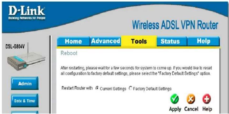
text_image
D-Link Building Networks for People Wireless ADSL VPN Router Home Advanced Tools Status Help Reboot After restarting, please wait for a few seconds for system to come up. If you would like to reset all configuration to factory default settings, please select the "Factory Default Settings" option. Restart Router with Current Settings Factory Default Settings Apply Cancel HelpFigure 5-6. Reboot
Click Restart with option Current Settings to reboot your router (and restore your last saved configuration).
If you wish to restart the router using the factory default settings (for example, after a firmware upgrade or if you have saved an incorrect configuration), select Factory Default Settings to reset to factory default settings.
You may also reset your router to factory settings by holding the small Reset pinhole button on the back of your router in for 10-12 seconds whilst the router is turned on.
Save Config to FLASH
After changing the router's configuration settings, you must save all of the configuration parameters to FLASH to avoid them being lost after turning off or resetting your router.

text_image
D-Link Building Networks for People Wireless ADSL VPN Router Home Advanced Tools Status Help DSL-G804V Save Config to FLASH Please click 'Apply' to start saving configuration to Flash. There will be a delay while saving as configuration information is written to FLASH chips. Admin Apply HelpFigure 5-7. Save Config to FLASH
Logout
To exit the router's web interface, choose Logout. Please ensure that you have saved the configuration settings before you logout.
Be aware that the router is restricted to only one PC accessing the configuration web pages at a time. Once a PC has logged into the web interface, other PCs cannot get access until the current PC has logged out of the web interface. If the previous PC forgets to logout, the second PC can access the page after a user-defined period, by default 3 minutes. You can modify this value using the Advanced – Device section of the web interface.

Status
Click the Status tab to access menus used to configure Device Info, ARP, Wireless, Routing, IPSec Status, PPTP Status, L2TP Status, DHCP, Email, Event Log, NAT Sessions, UPnP Portmap.
Device Information
Device Information detailed displays the current setting of your router such as LAN, WAN, Wireless, Port Status and Traffic Statistic.
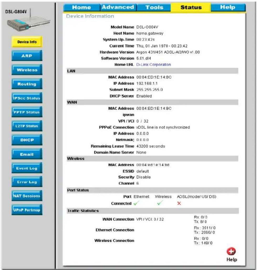
text_image
DSL-G804V Device Info ARP Wireless Routing IPSec Status PPTP Status L2TP Status DHCP Email Event Log Error Log NAT Sessions UPnP Portmap Home Advanced Tools Status Help Device Information Model Name DSL-0004V Host Name home.gateway System Up-Time 00:23:42s Current Time Thu, 01 Jan 1970 - 00:23:42 Hardware Version Argon 431/451 ADSL-A2/VO v1.00 Software Version 5.01.d14 Home URL D-Link Corporation LAN MAC Address 00:04:ED:1E:14:BC IP Address 192.168.1.1 Subnet Mask 255.255.255.0 DHCP Server Enabled WAN MAC Address 00:04:ED:1E:14:BC ipwan VPI /VCI 0 / 32 PPPoE Connection xDSL line is not synchronized IP Address 0.0.0.0 Netmask; 0.0.0.0 Remaining Lease Time 43200 seconds Domain Name Server None Wireless MAC Address 00:04:ed:1e:14:bd ESSID default Security Disable Channel 6 Port Status Port Ethernet Wireless ADSL(mode/ US/ DS) Connected ✓ ✓ ✗ Traffic Statistics WAN Connection VPI /VCI, 0 / 32 Rx: 0/0 Ethernet Connection Rx: 3511/0 Wireless Connection Tx: 2666/0 Rx: 0/0 Tx: 148/0 HelpFigure 6-1. Device Information
ARP
ARP (Address Resolution Protocol) Table shows the mapping of Internet (IP) addresses to Ethernet (MAC) addresses. This is useful as a quick way of determining the MAC address of the network interface of your PCs. Static – no means the ARP table entry is dynamically generated. Yes means the ARP table entry is added by the users.
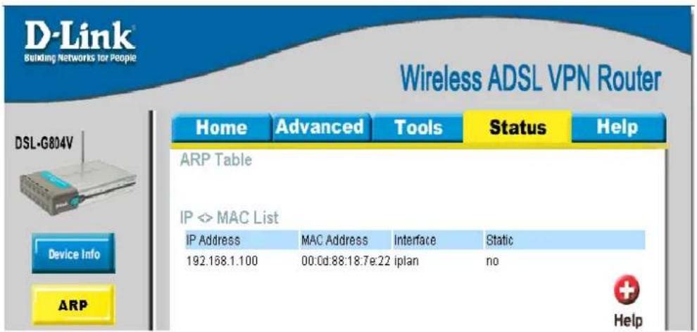
text_image
D-Link® Building Networks for People Wireless ADSL VPN Router Home Advanced Tools Status Help ARP Table IP <> MAC List IP Address MAC Address Interface Static 192.168.1.100 00:0d:88:18:7e:22 iplan no Device Info ARP HelpFigure 6-2. ARP Table
| Para meter | Description |
| IP Address | A list of IP addresses of devices on your LAN (Local Area Network) |
| MAC Address | The MAC (Media Access Control) addresses for each device on your LAN. |
| Interface | The interface name (on the router) that this IP Address connects to. |
| Static | Static status of the ARP table entry:“no” for dynamically-generated ARP table entries“yes” for static ARP table entries added by the user |
Wireless (Connect Wireless Client List)
Wireless Client table displays information of the AP client that is connect to the router.

text_image
D-Link Building Networks for People Wireless ADSL VPN Router Home Advanced Tools Status Help DSL-G804V Connected Wireless Client List The Wireless Client table below displays Wireless clients connected to the AP (Access Point). IP Address MAC Device Info ARP Wireless HelpFigure 6-3. Connect Wireless Client List
| Para meter | Description |
| IP Address | It is IP address of wireless client that joins this network. |
| MAC | The MAC address of wireless client. |
Routing Table
Two routing tables are displayed, Routing Table and RIP Routing Table.

text_image
D-Link Building Networks for People Wireless ADSL VPN Router Home Advanced Tools Status Help DSL-G804V Routing Table Routing Table Valid Destination Netmask Gateway/Interface Cost RIP Routing Table Valid Destination Netmask Cost Device Info ARP Wireless Routing HelpFigure 6-4. Routing Table
| Para meter | Description |
| Routing Table | |
| Valid | It indicates a successful routing status. |
| Destination | The IP address of the destination network. |
| Netmask | The destination netmask address. |
| Gateway/Interface | The IP address of the gateway or existing interface that this route will use. |
| Cost | The number of hops counted as the cost of the route. |
| RIP Routing Table | |
| Destination | The IP address of the destination network. |
| Netmask | The destination netmask address. |
| Gateway | The IP address of the gateway that this route will use. |
| Cost | The number of hops counted as the cost of the route. |
IPSec Status
IPSec Status shows details of your configured IPSec VPN connections.

text_image
D-Link Building Networks for People Wireless ADSL VPN Router Home Advanced Tools Status Help DSL-G804V IPSec Status VPN Tunnels Name Active Status Statistics Local Subnet Remote Subnet Remote Gateway SA Device Info ARP HelpFigure 6-5. IPSec Status
| Para meter | Description |
| Name | The name you assigned to the particular VPN entry. |
| Active | Whether the VPN Connection is currently Active. |
| Connection State | Whether the VPN is Conne cted or Disconnected. |
| Statistics | Statistics for this VPN Connection. |
| Local Subnet | The local IP Address or Subnet used. |
| Remote Subnet | The Subnet of the remote site. |
| Remote Gateway | The Remote Gateway IP address. |
| SA | The Security Association for this VPN entry. |
PPTP Status
PPTP Status shows details of your configured PPTP VPN connections.

text_image
D-Link Building Networks for People Wireless ADSL VPN Router Home Advanced Tools Status Help PPTP Status VPN/PPTP for Remote Access Application Name Type Enable Active Tunnel Connected Call Connected Encryption VPN/PPTP for LAN-to-LAN Application Name Type Enable Active Tunnel Connected Call Connected Encryption DSL-G804V Device Info ARP Wireless Routing HelpFigure 6-6. PPTP Status
| Para meter | Description |
| Name | The name you assigned to the particular PPTP connection in your VPN configuration. |
| Type | The type of connection (dial-in/dial-out). |
| Enable | Whether the connection is currently enabled. |
| Active | Whether the connection is currently active. |
| Tunnel Connected | Whether the VPN Tunnel is currently connected. |
| Call Connected | If the Call for this VPN entry is currently connected. |
| Encryption | The encryption type used for this VPN connection. |
L2TP Status
L2TP Status shows details of your configured L2TP VPN connections.

text_image
D-Link Building Networks for People Wireless ADSL VPN Router Home Advanced Tools Status Help L2TP Status VPN/L2TP for Remote Access Application Name Type Enable Active Tunnel Connected Call Connected Encryption VPN/L2TP for LAN-to-LAN Application Name Type Enable Active Tunnel Connected Call Connected Encryption Device Info ARP Wireless RoutingFigure 6-7. L2TP Status
| Para meter | Description |
| Name | The name you assigned to the particular L2TP connection in your VPN configuration. |
| Type | The type of connection (dial-in/dial-out). |
| Enable | Whether the connection is currently enabled. |
| Active | Whether the connection is currently active. |
| Tunnel Connected | Whether the VPN Tunnel is currently connected. |
| Call Connected | If the Call for this VPN entry is currently connected. |
| Encryption | The encryption type used for this VPN connection. |
DHCP Status
DHCP Status table displays DHCP Server assigned IP address information and Subnet Definitions.
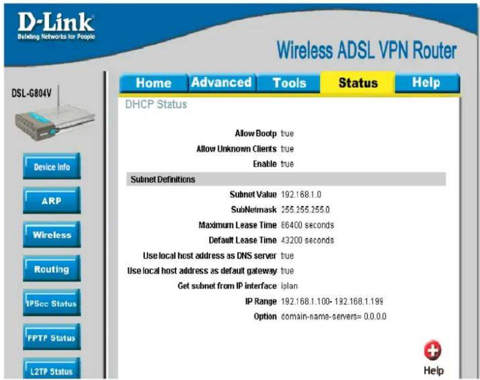
text_image
D-Link Building Networks for People Wireless ADSL VPN Router Home Advanced Tools Status Help DHCP Status Allow Bootp true Allow Unknown Clients true Enable true Subnet Definitions Subnet Value 192.168.1.0 SubNetmask 255.255.255.0 Maximum Lease Time 86400 seconds Default Lease Time 43200 seconds Use local host address as DNS server true Use local host address as default gateway true Get subnet from IP interface iplan IP Range 192.168.1.100- 192.168.1.199 Option domain-name-servers= 0.0.0.0 DSL-G804V Device Info ARP Wireless Routing IPSec Status FPTP Status L2TP Status HelpFigure 6-8. DHCP Status
| Para meter | Description |
| Allow Bootp | It shows in true or false. |
| Allow Unknown Clients | It shows in true or false. |
| Enable | It shows in true or false, if DHCP Server is in enabled. |
| Subnet Value/Subnetmask | This is the information of your DHCP Server IP subnet information. |
| Maximum Lease Time | The maximum lease time interval you allow. For more information, check “DHCP” under “Home” section. |
| Default Lease Time | The default lease time interval you allow. For more information, check “DHCP” under “Home” section. |
| Use local host address as DNS Server | It shows in true or false. |
| Use local host address as default gateway | It shows in true or false |
| Get subnet from IP interface | Iplan tells the subnet is based on the IP interface. |
Email Status
Email Status displays details and status of the Email Account you configured in Advanced -Email.

text_image
D-Link Building Networks for People Wireless ADSL VPN Router Home Advanced Tools Status Help DSL-G804V Email Status Email Account Account Name username POP3 Mail Server pop3.mail.com Email Status Disabled Device Info ARP Wireless HelpFigure 6-9. Email Status
Event Log
Event Log detailed displays router's event entries. Major events are logged to this window, such as when the router's ADSL connection is disconnected, as well as Firewall events when you have enabled Intrusion or Blocking Logging in the Advanced – Firewall section of the interface. Please see the Firewall section of this manual for more details on how to enable Firewall logging.

text_image
D-Link Building Networks for People Wireless ADSL VPN Router Home Advanced Tools Status Help DSL-G804V Event Log ---- system log buffer head ---- ---- system log buffer tail ---- Refresh Clear Device Info ARP Wireless Routing IPsec Status PPTP Status L2TP Status DHCP EmailFigure 6-10. Event Log
Error Log
Error Log displays any errors encountered by the router (e.g. invalid names given to entries) are logged to this window.
text_image
D-Link Building Networks for People Wireless ADSL VPN Router Home Advanced Tools Status Help Error Log When Process Error Log Refresh Device Info ARP Wireless HelpFigure 6-11. Error Log
NAT Sessions
NAT Sessions list all current NAT session between interface of types external (WAN) and internal (LAN).

text_image
D-Link® Building Networks for People Wireless ADSL VPN Router Home Advanced Tools Status Help DSL-G804V NAT Sessions Active NAT sessions between interface of types external and internal: Prot | Local IP: Port local/public | Remote IP: Port | Idle (sec. TCP | 192.168, 1.201: 1110/ 1110 | 64, 94.110, 12: 80 | 29 TCP | 192.168, 1. 99: 1982/ 1982 | 210.184.108.126: 80 | 729 TCP | 192.168, 1. 99: 1979/ 1979 | 207, 68.178.239: 80 | 542 TCP | 192.168, 1.202: 2011/ 2011 | 207, 46.107, 27: 1863 | 21 TCP | 192.168, 1.100: 1166/ 1166 | 207, 46.106, 90: 1863 | 18 TCP | 192.168, 1. 99: 1969/ 1969 | 207, 46.107, 22: 1863 | 673 ICMP | 192.168, 1.201: 512/ 512 | 168, 95, 4.211: 512 | 0 TCP : 6 sessions UDP : 0 sessions Others : 1 sessions Total : 7 sessions RefreshFigure 6-12. NAT Sessions
UPnP Portmap
UPnP Portmap list all port-mapping established using UPnP (Universal Plug and Play).
text_image
D-Link Building Networks for People Wireless ADSL VPN Router Home Advanced Tools Status Help DSL-G804V UPnP Portmap UPnP Portmap Table Refresh Device Info ARP Wireless HelpFigure 6-13. UPnP Portmap
Help
Help menu links provide more information for configuring various Router functions.
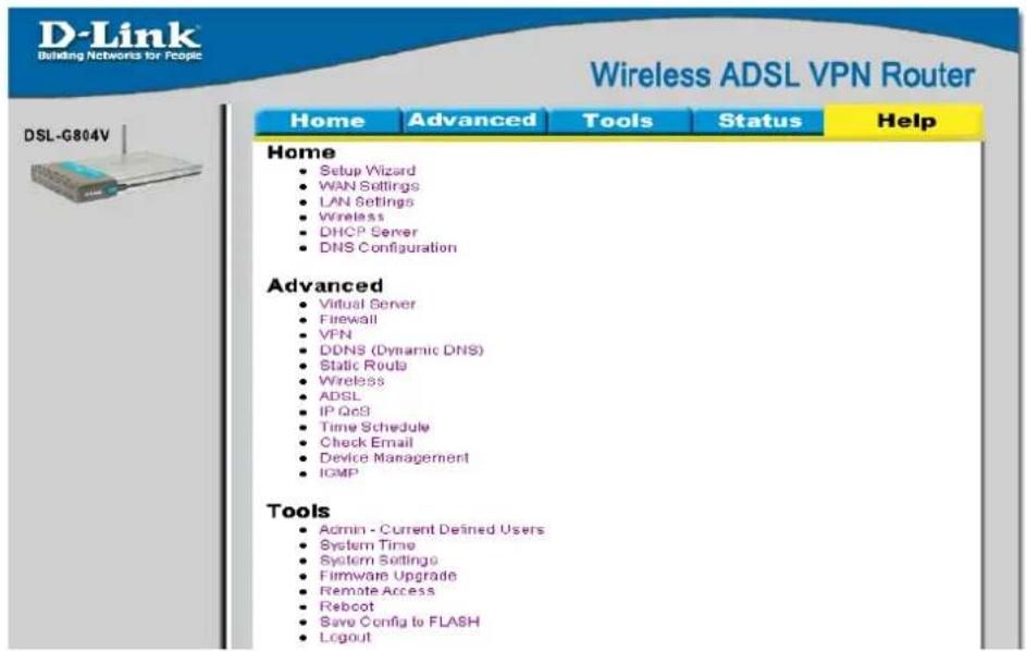
text_image
D-Link Building Networks for People Wireless ADSL VPN Router Home Advanced Tools Status Help Home • Setup Wizard • WAN Settings • LAN Settings • Wireless • DHCP Server • DNS Configuration Advanced • Virtual Server • Firewall • VPN • DDNS (Dynamic DNS) • Static Route • Wireless • ADSL • IP QoS • Time Schedule • Check Email • Device Management • ICMP Tools • Admin - Current Defined Users • System Time • System Settings • Firmware Upgrade • Remote Access • Reboot • Save Config to FLASH • LogoutFigure 6-14. Help

Technical Specifications
| GENERAL | ||
| Standards: | ITU G.992.1 (G.dmt) Annex A | RFC 1577 (IP over ATM) |
| ITU G.992.2 (G.lite) Annex A | RFC 1661 (PPP) | |
| ITU G.994.1 (G.Hs) | RFC 1994 (CHAP) | |
| ITU-T Rec. I.361 | RFC 1334 (PAP) | |
| ITU-T Rec. I.610 | RFC 2364 (PPP over ATM) | |
| IEEE 802.3 | RFC 1631 (NAT) | |
| IEEE 802.3u | RFC 1877 (Automatic IP assignment) | |
| IEEE 802.1d | RFC 2516 (PPP over Ethernet) | |
| RFC 791 (IP Routing) | Supports RFC 2131 and RFC 2132 (DHCP) | |
| RFC 792 (UDP) | Compatible with all T1.413 issue 2 (full rate DMT over analog POTS), and CO DSLAM equipment | |
| RFC 826 (ARP) | ||
| RFC 1058 (RIP 1) | Supports ATM Forum UNI V3.1 PVC | |
| RFC 1389 (RIP 2) | ||
| RFC 1213 compliant | ||
| RFC 1483 (Bridged Ethernet) | ||
| Protocols: | TCP/IP | DHCP |
| UDP | BOOTP | |
| RIP-1 | ARP | |
| RIP-2 | AAL5 | |
| IGMP | ||
| Data Transfer Rate: | G.dmt full rate: Downstream up to 8 Mbps | |
| Upstream up to 640 Kbps | ||
| G.lite: Downstream up to 1.5 Mbps | ||
| Upstream up to 512 Kbps | ||
| Media Interface: | RJ-11 port ADSL telephone line connection | |
| RJ-45 port for 10/100BASET Ethernet connection | ||
| Physical and Environmental | ||
| DC Inputs:Power Adapter: | Input: 100V ~ 240V AC 50 ~ 60HzOutput: 12V DC, 1A | |
| Power Consumption: | 12 Watts (max) | |
| Operating Temperature: | 0° to 40°C (32° - 104°F) | |
| Humidity: | 5 to 95% (non-condensing) | |
| Dimensions: | 180 x 141 x 30 mm | |
| Weight: | 332 g | |
| EMI: | CE Class B, FCC Class B (Part 15) | |
| Safety: | CSA International | |
| Reliability: | Mean Time Between Failure (MTBF) min. 4 years | |

IP Address Setup
The DSL-G804V is designed to provide network administrators maximum flexibility for IP addressing on the Ethernet LAN. The easiest IP setup choice in most cases is to let the Router do it using DHCP, which is enabled by default. This appendix briefly describes various options including DHCP, used for IP setup on a LAN. If you are new to IP networking, the next appendix provides some background information on basic IP concepts.
Assigning Network IP Addresses
The IP address settings, which include the IP address, subnet mask and gateway IP address are the first and most important internal network settings that need to be configured. The Router is assigned a default LAN IP address and subnet mask. If you do not have a preexisting IP network and are setting one up now, using the factory default IP address settings can greatly ease the setup process. If you already have a preexisting IP network, you can adjust the IP settings for the Router to fit within your existing scheme.
Using the Default IP Address
The Router is shipped with a preset default IP address setting of 192.168.1.1 for the LAN port. There are two ways to use this default IP address, you can manually assign an IP address and subnet mask for each PC on the LAN or you can instruct the Router to automatically assign them using DHCP. The simplest method is to use DHCP. The DHCP function is active by default.
Manual IP Address Assignment
Manually configuring IP settings for the LAN means you must manually set an IP address, subnet mask and IP address of the default gateway (the Router's IP address) on each networked computer. The example listed below describes IP configuration for computers running Windows 95 or Windows 98. Regardless of what operating system is used on each workstation, the three network IP settings must be defined so the network interface used by each workstation can be identified by the Router, and vice versa. For detailed information about configuring your workstations IP settings, consult the user's guide included with the operating system or the network interface card (NIC).
- In Windows 95/98, click on the Start button, go to Settings and choose Control Panel.
- In the window that opens, double-click on the Network icon.
- Under the Configuration tab, select the TCP/IP component and click Properties.
- Choose the Specify an IP address option and edit the address settings accordingly. Consult the table below for IP settings on a Class C network.
| Using Default IP without DHCP | |||
| Host IP Address | Subnet Mask | Gateway IP | |
| Router | 192.168.1.1 | 255.255.255.0 | |
| Computer #1 | 192.168.0.2 | 255.255.255.0 | 192.168.1.1 |
| Computer #2 | 192.168.0.3 | 255.255.255.0 | 192.168.1.1 |
| Computer #3 | 192.168.0.4 | 255.255.255.0 | 192.168.1.1 |
IP Setup - Example #1
Please note that when using the default IP address as in the above example, the first three numbers in the IP address must always be the same with only the fourth number changing. The first three numbers define the network IP address (all machines must belong to the same IP network), while the last number denotes the host IP
address (each computer must have a unique address to distinguish it on the network). The IP address scheme used in Example #1 can be used for any LAN that requires up to 253 separate IP addresses (excluding the Router). Notice that the subnet mask is the same for all machines and the default gateway address is the LAN IP address of the Router.
It is a good idea to make a note of each device's IP address for reference during troubleshooting or when adding new stations or devices.
Using DHCP
The second way to use the default settings is to allow the Router to automatically assign IP settings for workstation using DHCP. To do this, simply make sure your computers' IP addresses are set to 0.0.0.0 (under Windows, choose the option Obtain an IP address automatically in the TCP/IP network component described above). When the computers are restarted, their IP settings will automatically be assigned by the Router. The Router is set by default to use DHCP. See the discussion in Chapter 5 for information on how to use configure the Router for DHCP.
Changing the IP Address of the Router
When planning your LAN IP address setup, you may use any scheme allowed by rules that govern IP assignment. It may be more convenient or easier to remember an IP scheme that use a different address for the Router. Or you may be installing the Router on a network that has already established the IP settings. Changing the IP address is a simple matter and can be done using the web manager (see LAN IP Address in Chapter 5). If you are incorporating the Router into a LAN with an existing IP structure, be sure to disable the DHCP function. Also, consider the effects of the NAT function which is enable by default.
An IP addressing scheme commonly used for Ethernet LANs establishes 10.0.0.1 as the base address for the network. Using Example #2 below, the Router is assigned the base address 10.0.0.1 and the remaining addresses are assigned manually or using DHCP.
| Alternative IP Assignment | |||
| Host IP Address | Subnet Mask | Gateway IP | |
| Router | 10.0.0.1 | 255.255.255.0 | |
| Computer #1 | 10.0.0.2 | 255.255.255.0 | 192.168.1.1 |
| Computer #2 | 10.0.0.3 | 255.255.255.0 | 192.168.1.1 |
| Computer #3 | 10.0.0.4 | 255.255.255.0 | 192.168.1.1 |
IP Setup - Example #2
These two examples are only examples you can use to help you get started. If you are interested in more advanced information on how to use IP addressing on a LAN there are numerous resources freely available on the Internet. There are also many books and chapters of books on the subject of IP address assignment, IP networking and the TCP/IP protocol suite.

IP Concepts
This appendix describes some basic IP concepts, the TCP/IP addressing scheme and show how to assign IP Addresses.
When setting up the Router, you must make sure it has a valid IP address. Even if you will not use the WAN port (ADSL port), you should, at the very least, make sure the Ethernet LAN port is assigned a valid IP address. This is required for telnet, in-band SNMP management, and related functions such as "trap" handling and TFTP firmware download.
IP Addresses
The Internet Protocol (IP) was designed for routing data between network sites all over the world, and was later adapted for routing data between networks within any site (often referred to as “subnetworks” or “subnets”). IP includes a system by which a unique number can be assigned to each of the millions of networks and each of the computers on those networks. Such a number is called an IP address.
To make IP addresses easy to understand, the originators of IP adopted a system of representation called “dotted decimal” or “dotted quad” notation. Below are examples of IP addresses written in this format:
201.202.203.204
189.21.241.56
125.87.0.1
Each of the four values in an IP address is the ordinary decimal (base 10) representation of a value that a computer can handle using eight "bits" (binary digits — 1s and 0s). The dots are simply convenient visual separators.
Zeros are often used as placeholders in dotted decimal notation; 189.21.241.56 can therefore also appear as 189.021.241.056.
IP networks are divided into three classes on the basis of size. A full IP address contains a network portion and a "host" (device) portion. The network and host portions of the address are different lengths for different classes of networks, as shown in the table below.

text_image
0 8 16 24 31 Class A 0 netid hostid Class B 1 0 netid hostid Class C 1 1 0 netid hostid Class D 1 1 1 0 multicast address Class E 1 1 1 1 0 reserved for future useNetworks attached to the Internet are assigned class types that determine the maximum number of possible hosts per network. The previous figure illustrates how the net and host portions of the IP address differ among the three classes. Class A is assigned to networks that have more than 65,535 hosts; Class B is for networks that have 256 to 65534 hosts; Class C is for networks with less than 256 hosts.
| IP Network Classes | |||
| Class | Maximum Number of Networks in Class | Network Addresses (Host Portion in Parenthesis) | Maximum Number of Hosts per Network |
| A 126 | 1(.0.0.0) to 126(.0.0) | 0) 16,777,214 | |
| B 16 | 382 128.1(.0.0) to 19 | 1.254(.0.0) 65,534 | |
| C 2,0 | 97,150 192.0.1(.0) to | 223.255.254(.0) 254 | |
Note: All network addresses outside of these ranges (Class D and E) are either reserved or set aside for experimental networks or multicasting.
When an IP address's host portion contains only zero(s), the address identifies a network and not a host. No physical device may be given such an address.
The network portion must start with a value from 1 to 126 or from 128 to 223. Any other value(s) in the network portion may be from 0 to 255, except that in class B the network addresses 128.0.0.0 and 191.255.0.0 are reserved, and in class C the network addresses 192.0.0.0 and 223.255.255.0 are reserved.
The value(s) in the host portion of a physical device's IP address can be in the range of 0 through 255 as long as this portion is not all-0 or all-255. Values outside the range of 0 to 255 can never appear in an IP address (0 to 255 is the full range of integer values that can be expressed with eight bits).
The network portion must be the same for all the IP devices on a discrete physical network (a single Ethernet LAN, for example, or a WAN link). The host portion must be different for each IP device — or, to be more precise, each IP-capable port or interface — connected directly to that network.
The network portion of an IP address will be referred to in this manual as a network number; the host portion will be referred to as a host number.
To connect to the Internet or to any private IP network that uses an Internet-assigned network number, you must obtain a registered IP network number from an Internet-authorized network information center. In many countries you must apply through a government agency, however they can usually be obtained from your Internet Service Provider (ISP).
If your organization's networks are, and will always remain, a closed system with no connection to the Internet or to any other IP network, you can choose your own network numbers as long as they conform to the above rules.
If your networks are isolated from the Internet, e.g. only between your two branch offices, you can assign any IP Addresses to hosts without problems. However, the Internet Assigned Numbers Authority (IANA) has reserved the following three blocks of IP Addresses specifically for private (stub) networks:
| Class | Beginning Address | Ending Address |
| A | 10.0.0.0 | 10.255.255.255 |
| B | 172.16.0.0 | 172.31.255.255 |
| C | 192.168.0.0 | 192.168.255.255 |
It is recommended that you choose private network IP Addresses from the above list. For more information on address assignment, refer to RFC 1597, Address Allocation for Private Internets and RFC 1466, Guidelines for Management of IP Address Space.
Subnet Mask
In the absence of subnetworks, standard TCP/IP addressing may be used by specifying subnet masks as shown below.
| IP Class Subnet Mask | |
| Class A 255.0.0.0 | |
| Class B 255.255.0.0 | |
| Class C 255.255.255.0 | |
Subnet mask settings other than those listed above add significance to the interpretation of bits in the IP address. The bits of the subnet mask correspond directly to the bits of the IP address. Any bit an a subnet mask that is to correspond to a net ID bit in the IP address must be set to 1.

Microfilters and Splitters
Most ADSL clients will be required to install a simple device that prevents the ADSL line from interfering with regular telephone services. These devices are commonly referred to as microfilters or sometimes called (inaccurately) line splitters. They are easy to install and use standard telephone connectors and cable.
Some ADSL service providers will send a telecommunications technician to modify the telephone line, usually at the point where the telephone line enters the building. If a technician has divided or split your telephone line into two separate lines - one for regular telephone service and the other for ADSL – then you do not need to use any type of filter device. Follow the instructions given to you by your ADSL service provider about where and how you should connect the Modem to the ADSL line.
Microfilters
Unless you are instructed to use a "line splitter" (see below), it will be necessary to install a microfilter (low pass filter) device for each telephone or telephone device (answering machines, Faxes etc.) that share the line with the ADSL service. Microfilters are easy-to-install, in-line devices, which attach to the telephone cable between the telephone and wall jack. Microfilters that install behind the wall plate are also available. A typical in-line microfilter installation is shown in the diagram below.
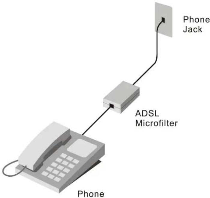
flowchart
graph TD
    A["Phone"] --> B["ADSL Microfilter"]
    B --> C["Phone Jack"]
Microfilter Installation
Important: Do not install the microfilter between the Modem and the telephone jack. Microfilters are only intended for use with regular telephones, Fax machines and other regular telephone devices.
Line Splitter
If you are instructed to use a "line splitter", you must install the device between the Modem and the phone jack. Use standard telephone cable with standard RJ-11 connectors. The splitter has three RJ-11 ports used to connect to the wall jack, the Modem and if desired, a telephone or telephone device. The connection ports are typically labeled as follows:
Line - This port connects to the wall jack.
ADSL - This port connects to the Modem.
Phone - This port connects to a telephone or other telephone device.
The diagram below illustrates the proper use of the splitter.

flowchart
graph TD
    A["Phone"] --> B["DSL-G804V"]
    B --> C["PC"]
    D["Line Splitter"] --> B
    E["Phone Jack"] --> B
Line Splitter Installation
Australia
D-Link
Australia
1 Giffnock Avenue, North Ryde, NSW 2113,
Sydney,
Australia
TEL: 61-2-8899-1800 FAX: 61-2-8899-1868
TOLL FREE (Australia): 1800-177100
URL:
www.dlink.com.au
E-MAIL:
support@dlink.com.au & info@dlink.com.au
Brazil D-Link Brasil Ltda.
Edificio Manoel Tabacow Hydal,
Rua Tavares Cabral 102 Sala 31, 05423-030
2180 Winston Park Drive, Oakville,
Ontario, L6H 5W1 Canada
TEL: 1-905-829-5033 FAX: 1-905-829-5095
TOLL FREE: 1-800-354-6522 URL: www.dlink.ca
FTP: ftp.dlinknet.com E-MAIL: techsup@dlink.ca
Chile D-Link South America (Sudamérica)
Isidora Goyenechea 2934 Of. 702, Las Condes Fono,
2323185, Santiago, Chile, S. A.
TEL: 56-2-232-3185 FAX: 56-2-232-0923
URL:
www.dlink.cl
E-MAIL: ccasassu@dlink.cl & tsilva@dlink.cl
China
D-Link
China
15^th Floor, Science & Technology Tower,
No.11, Baishiqiao Road, Haidan District, 100081 Beijing, China
TEL: 86-10-68467106 FAX: 86-10-68467110
URL:
www.dlink.com.cn
E-MAIL:
liwei@digitalchina.com.cn
Denmark
D-Link
Denmark
Naverland Denmark, Naverland 2, DK-2600 Glostrup, Copenhagen, Denmark
TEL: 45-43-969040 FAX:45-43-424347
URL: www.dlink.dk E-MAIL: info@dlink.dk
Egypt D-Link Middle East
7 Assem Ebn Sabet Street, Heliopolis, Cairo, Egypt
TEL: 202-245-6176 FAX: 202-245-6192
URL:
www.dlink-me.com
E-MAIL: support@dlink-me.com & fateen@dlink-me.com
Finland
D-Link
Finland
Pakkalankuja 7A, FIN-0150 Vantaa, Finland
TEL: 358-9-2707-5080 FAX: 358-9-2707-5081
URL:
www.dlink-fi.com
France
D-Link
France
Plot No.5, Bandra-Kurla Complex Rd., Off Cst Rd.,
Santacruz (East), Mumbai, 400 098 India
TEL:
91-022-652-6696/6578/6623
FAX:
91-022-652-8914/8476
URL: www.dlink-india.com & www.dlink.co.in
E-MAIL:
service@dlink.india.com & tushars@dlink-india.com
Italy D-Link Mediterraneo Srl/D-Link Italia
Via Nino Bonnet n. 6/B, 20154, Milano, Italy
TEL: 39-02-2900-0676 FAX: 39-02-2900-1723
URL: www.dlink.it E-MAIL: info@dlink.it
Japan
D-Link
Japan
10F, 8-8-15 Nishi-Gotanda, Shinagawa-ku, Tokyo 141, Japan
TEL: 81-3-5434-9678 FAX: 81-3-5434-9868
URL: www.d-link.co.jp E-MAIL: kida@d-link.co.jp
Netherlands
D-Link
Benelux
Fellenoord 130 5611 ZB, Eindhoven, The Netherlands
TEL: 31-40-2668713 FAX: 31-40-2668666
URL: www.d-link-benelux.nl & www.dlink-benelux.be
E-MAIL:
info@dlink-benelux.nl & info@dlink-benelux.be
Norway
D-Link
Norway
Waldemar Thranesgate 77, 0175 Oslo, Norway
TEL: 47-22-99-18-90 FAX: 47-22-20-70-39 SUPPORT: 800-10-610
URL:
www.dlink.no
Russia D-Link Russia
Michurinski Prospekt 49, 117607 Moscow, Russia
TEL: 7-095-737-3389 & 7-095-737-3492
FAX: 7-095-737-3390 URL: www.dlink.ru
E-MAIL:
vl@dlink.ru
Singapore D-Link International
1 International Business Park, #03-12 The Synergy, Singapore 60991
TEL: 6-6774-6233 FAX: 6-6774-6322
E-MAIL: info@dlink.com.sg URL: www.dlink-intl.com
South Africa D-Link South Africa
Unit 2, Parkside, 86 Oak Avenue, Highveld Technopark,
Centurion, Gauteng, South Africa
TEL: 27-12-665-2165 FAX: 27-12-665-2186
URL: www.d-link.co.za E-MAIL: attie@d-link.co.za
Spain D-Link Iberia (Spain and Portugal)
Sabino de Arana, 56 bajos, 08028 Barcelona, Spain
TEL: 34 93 409 0770 FAX: 34 93 491 0795
URL: www.dlink.es E-MAIL: info@dlink.es
Sweden
D-Link
Sweden
P. O. Box 15036, S-167 15 Bromma, Sweden
TEL: 46-8-564-61900 FAX: 46-8-564-61901
URL: www.dlink.se E-MAIL: info@dlink.se
Taiwan
D-Link
Taiwan
2F, No. 119 Pao-chung Road, Hsin-tien, Taipei, Taiwan
TEL: 886-2-2910-2626 FAX: 886-2-2910-1515
URL: www.dlinktw.com.tw E-MAIL: dssqa@tsc.dlinktw.com.tw
Turkey
D-Link Middle East
Mecidiyekoy, Istanbul, Turkey
TEL: 90-212-213-3400 FAX: 90-212-213-3420
E-MAIL:
smorovati@dlink-me.com
U.A.E.
D-Link Middle East
CHS Aptec (Dubai), P.O. Box 33550 Dubai, United Arab Emirates
TEL: 971-4-366-885 FAX: 971-4-355-941
E-MAIL:
Wxavier@dlink-me.com
U.K. D-Link Europe (United Kingdom) Ltd
4 ^th Floor, Merit House, Edgware Road, Colindale, London
NW9 5AB United Kingdom
TEL: 44-020-8731-5555 SALES: 44-020-8731-5550
FAX: 44-020-8731-5511 SALES: 44-020-8731-5551
BBS: 44 (0) 181-235-5511
URL: www.dlink.co.uk E-MAIL: info@dlink.co.uk
U.S.A.
D-Link
U.S.A.
17575 Mt. Herrmann, Fountain Valley, CA 92708
TEL: 1-714-885-6000 FAX: 1-866-743-4905
INFO: 1-800-326-1688 URL: www.dlink.com
E-MAIL:
tech@dlink.com & support@dlink.com
Registration Card
Print, type or use block letters.
Your name: Mr./Ms
Organization:
Dept.
Your title at organization:
Telephone:
Fax:
Organization's full address:
Country:
Date of purchase (Month/Day/Year):
| Product Model | Product Serial No. * Product installed in type of computer (e.g., Compaq 486) | * Product installed in computer serial No. | |
(* Applies to adapters only)
Product was purchased from:
Reseller's name:
Telephone:
Fax:
Reseller's full address:
Answers to the following questions help us to support your product:
- Where and how will the product primarily be used?
□Home □Office □Travel □Company Business □Home Business □Personal Use
- How many employees work at installation site?
□1 employee □2-9 □10-49 □50-99 □100-499 □500-999 □1000 or more
- What network protocol(s) does your organization use?
☐XNS/IPX ☐TCP/IP ☐DECnet ☐Others
- What network operating system(s) does your organization use?
□D-Link LANsmart □Novell NetWare □NetWare Lite □SCO Unix/Xenix □PC NFS □3Com 3+Open
□Banyan Vines □DECnet Pathwork □Windows NT □Windows NTAS □Windows '95
□Others
- What network management program does your organization use?
□D-View □HP OpenView/Windows □HP OpenView/Unix □SunNet Manager □Novell NMS
□NetView 6000 □Others
- What network medium/media does your organization use?
□Fiber-optics □Thick coax Ethernet □Thin coax Ethernet □10BASE-T UTP/STP
□ 100BASE-TX □100BASE-T4 □100VGAnyLAN □Others
- What applications are used on your network?
□Desktop publishing □Spreadsheet □Word processing □CAD/CAM
□Database management □Accounting □Others
- What category best describes your company?
□Aerospace □Engineering □Education □Finance □Hospital □Legal □Insurance/Real Estate □Manufacturing
□Retail/Chainstore/Wholesale □Government □Transportation/Utilities/Communication □VAR
□System house/company □Other
- Would you recommend your D-Link product to a friend?
□Yes □No □Don't know yet
- Your comments on this product?

text_image
PLEASE PLACE STAMP HERE10