95-7298B - Car stereo AXESS - Free user manual and instructions
Find the device manual for free 95-7298B AXESS in PDF.

User questions about 95-7298B AXESS
0 question about this device. Answer the ones you know or ask your own.
Ask a new question about this device
Download the instructions for your Car stereo in PDF format for free! Find your manual 95-7298B - AXESS and take your electronic device back in hand. On this page are published all the documents necessary for the use of your device. 95-7298B by AXESS.
USER MANUAL 95-7298B AXESS
natural_image
Interior view of a car dashboard with air filters, air vent, and control panel (no visible text or symbols)Kia Sportage (with auto climate control w/o factory amplifier) 2020-2021
Visit MetraOnline.com for more detailed information about the product and up-to-date vehicle specific applications
KIT FEATURES
• ISO DDIN radio provision
- Integrated electronics with laser etched graphics retain the factory climate control display features.
- Retains factory steering wheel controls and back up camera.
- Painted scratch resistant matte black.
TABLE OF CONTENTS
Dash Disassembly 2-3
Kit Preparation 4-6
Kit Assembly 7
Axxess Interface Installation 8-15
KIT COMPONENTS
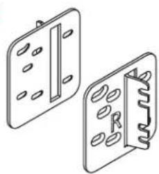
• A) Radio trim panel • B) Radio brackets • C) Climate display • D) Wiring harness (not shown)
A

natural_image
Isometric line drawing of a rectangular electronic device housing (no text or symbols)B

natural_image
Two technical line drawings of metal bracket components with holes and slots (no text or symbols)C

WIRING & ANTENNA CONNECTIONS
Wiring Harness: Included with kit
Antenna Adapter: Included with kit
TOOLS REQUIRED
- Panel removal tool • Phillips screwdriver
- Pick tool
Attention! With the key out of the ignition, disconnect the negative battery terminal before installing this product. Ensure that all installation connections are secure before cycling the ignition to test this product.
DASH DISASSEMBLY
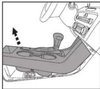
- Unclip and slide the top of the center console back slightly. (Figure A)
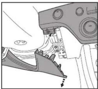
- Unclip and remove the panel on the end of the passenger side of the dash, then remove (1) Phillips screw exposed. (Figure B)
natural_image
Diagram of a car intake manifold showing the lever and mode (no text or symbols)(Figure A) (Figure C)
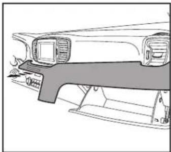
- Unclip the panel above the glove box. Unplug the passenger airbag light, then remove the panel. (Figure C)
- Remove (2) Phillips screws securing the radio display and a/c vent panel, then unclip and remove the panel. (Figure D)
Continued on the next page
natural_image
Technical line drawing of a vehicle's front and side components (no text or symbols)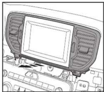
natural_image
Technical line drawing of a car dashboard with ventilation grilles and control panel (no text or symbols)
natural_image
Diagram of a car interior showing a curved panel and directional arrows (no text or symbols)(Figure B) (Figure D)
DASH DISASSEMBLY (CONT.)
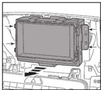
- Remove (4) Phillips screws securing the radio. Slide the radio out, then unplug and remove the radio. (Figure E)
- Remove (3) Phillips screw securing the climate control panel. (Figure F)
natural_image
Interior view of a vehicle dashboard with control panel and buttons (no text or symbols visible)(Figure E) (Figure G)
- Remove (1) Phillips screw securing the lower right side drivers knee bolster. Unsnap the bolster just enough to access the (1) Phillips screw securing the climate control panel, then remove the screw. (Figure 6)
- Unclip the climate/radio control panel from the dash, unplug the connectors, then remove the panel. (Figure H)
Continue to Kit Preparation
natural_image
Mechanical assembly diagram showing a gear and lever mechanism (no text or symbols)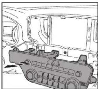
natural_image
Technical line drawing of a car interior showing a vehicle chassis with no visible text or symbols
natural_image
Technical line drawing of a vehicle chassis with no visible text or symbols(Figure F) (Figure H)
KIT PREPARATION
Radio Trim Panel Installation
To the factory radio trim panel:
- Snap in the 95-7298B radio trim panel to the factory panel. (Figure A)
Continued on the next page

natural_image
Technical illustration of a car air vent assembly with a magnified inset showing internal components (no text or symbols)(Figure A)
KIT PREPARATION (CONT.)
Climate Display Installation
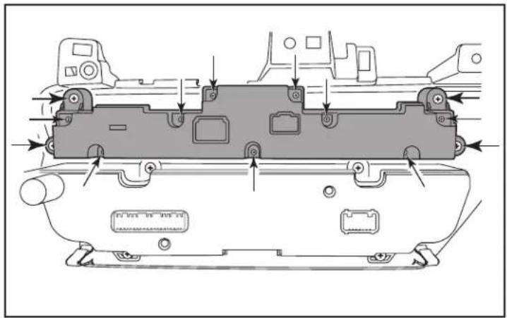
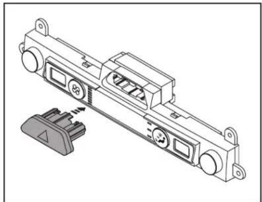
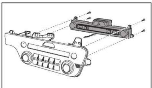
- Remove (4) Phillips screws securing the radio/hazard assembly to the climate/radio control panel, then unclip and remove the assembly. (Figure C, heavier arrows)
- Remove (9) Phillips screws securing the back cover to the radio/hazard assembly, then remove the cover. (Figure C)
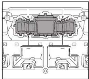
- Using a pick tool, gently release (4) clips holding the hazard switch to the assembly, then remove the switch. (Figure D)
Continued on the next page
natural_image
Technical diagram of a vehicle chassis with internal components and directional arrows indicating movement (no text or labels)(Figure C)
natural_image
Technical diagram of a mechanical component with internal channels and mounting brackets (no text or labels)(Figure D)
KIT PREPARATION (CONT.)
- Clip the hazard switch into the climate display. (Figure E)
- Secure the climate-display/hazard-switch assembly to the climate control panel using the factory screws. (Figure F)
Continue to Kit Assembly
natural_image
Technical line drawing of a mechanical assembly with mounting holes and internal components (no text or symbols)(Figure E)

natural_image
Technical line drawing of a mechanical component with no visible text or symbols(Figure F)
KIT ASSEMBLY
ISO DDIN radio provision
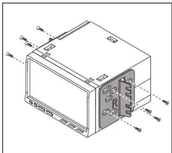
- Secure the radio brackets to the radio using the screws supplied with the radio. (Figure A)
Continue to Axxess Interface Installation
natural_image
Technical line drawing of a device housing with mounting holes and internal components (no text or symbols)(Figure A)
AXXESS INTERFACE INSTALLATION
FEATURES
- Retains audio controls on the steering wheel via an ASWC-1
- Provides NAV outputs (speed sense)
- Retains the factory AUX-IN jack
- Retains the factory backup camera
- Includes an AX-CAM6V 12-to-6V step-down for the factory camera
- Retains balance and fade
COMPONENTS
• Female 3.5mm connector with stripped leads
• ASWC-1
- AX-CAM6V
- Wiring harness
TABLE OF CONTENTS
Connections....9-10
Installation....10
Final Assembly....11
Programming the ASWC-1 and climate display 11
(ASWC-1) Steering wheel control settings 12-15
- L.E.D. feedback
- Changing radio type
- Remapping the steering wheel control buttons
- Dual assignment instructions (long button press)
TOOLS REQUIRED
- Crimping tool and connectors, or solder gun, solder, and heat shrink
- Tape • Wire cutter • Zip ties
CONNECTIONS
From the wiring harness included with the kit to the aftermarket radio:
- Connect the (2) Black wires, the Black wire labeled "CAMERA GROUND", and also the Black wire from the AX-CAM6V, to the ground wire.
- Connect the Yellow wire to the battery wire.
- Connect the Red wire to the accessory wire.
- Connect the Red wire labeled "CAMERA POWER 6V" to the Blue/Red wire from the AX-CAM6V.
- Connect the Blue wire to the power antenna wire.
- If the aftermarket radio has an illumination wire, connect the Orange wire to it.
- Connect the Gray wire to the right front positive speaker output.
- Connect the Gray/Black wire to the right front negative speaker output.
- Connect the White wire to the left front positive speaker output.
- Connect the White/Black wire to the left front negative speaker output.
- Connect the Green wire to the left rear positive speaker output.
- Connect the Green/Black wire to the left rear negative speaker output.
- Connect the Purple wire to the right rear positive speaker output.
- Connect the Purple/Black wire to the right rear negative output.
The following (1) wire is only for a multimedia/navigation radio that requires this wire.
- Connect the Blue/Pink wire to the VSS/speed sense wire.
- Connect the Blue/White wire from the AX-CAM6V to a wire that has power while the vehicle is in reverse. This wire will have to be located in the vehicle.
- If retaining the factory AUX-In jack, connect the Red and White RCA jacks to the audio AUX-IN jacks from the aftermarket radio.
- Connect the Yellow RCA jack to the backup camera input.
Continued on the next page
CONNECTIONS (CONT.)
3.5mm jack steering wheel control retention:
The 3.5mm jack is to be used to retain audio controls on the steering wheel.
- For the radios listed below, connect the female 3.5mm connector with stripped leads, to the male 3.5mm SWC jack from the wiring harness included with the kit. Any remaining wires tape off and disregard:
- Eclipse: Connect the steering wheel control wire, normally Brown, to the Brown/White wire of the connector. Then connect the remaining steering wheel control wire, normally Brown/White, to the Brown wire of the connector.
• Metra OE: Connect the steering wheel control Key 1 wire(Gray) to the Brown wire. - Kenwood or select JVC with a steering wheel control wire: Connect the Blue/Yellow wire to the Brown wire.
Note: If your Kenwood radio auto detects as a JVC, manually set the radio type to Kenwood. See the instructions under changing radio type.
• XITE: Connect the steering wheel control SWC-2 wire from the radio to the Brown wire.
• Parrot Asteroid Smart or Tablet: Connect the 3.5mm jack into the AX-SWC-PARROT (sold separately), and then connect the 4-pin connector from the AX-SWC-PARROT into the radio.
Note: The radio must be updated to rev. 2.1.4 or higher software.
- Universal "2 or 3 wire" radio: Connect the steering wheel control wire, referred to as Key-A or SWC-1, to the Brown wire of the connector. Then connect the remaining steering wheel control wire, referred to as Key-B or SWC-2, to the Brown/White wire of the connector. If the radio comes with a third wire for ground, disregard this wire. Note: After the interface has been programmed to the vehicle, refer to the manual provided with the radio for assigning the SWC buttons. Contact the radio manufacturer for more information
- For all other radios: Connect the 3.5mm jack from the wiring harness included with the kit into the jack on the aftermarket radio designated for an external steering wheel control interface. Please refer to the aftermarket radios manual if in doubt as to where the 3.5mm jack goes to.
INSTALLATION
With the key in the off position:
- Connect the wiring harness included with the kit to the climate-display/hazard-switch assembly, and then to the wiring harness in the vehicle.
- Locate the factory antenna connector in the dash and complete all necessary connections to the radio. Use the antenna adapter provided to adapt the factory antenna connector to the aftermarket radio.
- Connect the wiring harness included with the kit to the ASWC-1.
Attention! If retaining steering wheel controls, ensure that the SWC jack/wire is connected to the radio before proceeding. If this step is skipped, the ASWC-1 will need to be reset for the steering wheel controls to function.
PROGRAMMING THE ASWC-1 AND CLIMATE DISPLAY
Programming the ASWC-1:
- Press and hold the "Volume-Up" button on the steering wheel, then turn the ignition on. The L.E.D. will start flashing rapidly, which means the ASWC-1 is looking for the vehicle and the radio.
Note: If the L.E.D. didn't start flashing rapidly, press the reset button for 3 seconds, while still holding the "Volume-Up" button.
- After a few seconds the L.E.D. should stop flashing rapidly, then go out for approximately 2 seconds.
- After approximately 2 seconds there will be a series of 7 Green flashes, some short, and some long. The long flashes represent the wires that are connected to the ASWC-1.
Tip: Knowing this will help to troubleshoot, if need be.
- The L.E.D. will pause for another 2 seconds, then flash Red up to 18 times depending on which radio is connected to the ASWC-1. Refer to the L.E.D. feedback section for information.
- This is the end of the auto detection stage. If the ASWC-I detected the vehicle and the radio successfully, the L.E.D. will light up solid. Release from holding the "Volume-Up" button.
- Test the steering wheel controls for proper operation. Refer to “(ASWC-1) Steering wheel control settings” for customizing the buttons, if so desired.
Programming the climate display:
- Turn the parking lights on.
- Turn the vehicles light dimmer all the way down, then all the way up.
- Turn the lights off.
- Test all functions of the installation for proper operation, before reassembling the dash.
FINAL ASSEMBLY
- Secure the climate control assembly to the dash in reverse order of disassembly using the factory screws.
- Secure the radio assembly to the dash using the factory screws.
- Reassemble the dash in reverse order of disassembly to complete the installation.
ASWC-1 STEERING WHEEL CONTROL SETTINGS
L.E.D. feedback
The (18) Red L.E.D. flashes represent what brand radio the ASWC-1 believes it is connected to. Each flash represents a different radio Manufacturer. For example, if you are installing a JVC radio, the ASWC-1 will flash Red (5) times, and then stop. Following is a legend that dictates which radio Manufacturer corresponds to which flash.
L.E.D. Feedback Legend
| Flash Count Radio | Flash Count Radio |
| 1 Eclipse (type 1) †2 Kenwood ‡3 Clarion (type 1) †4 Sony / Dual5 JVC6 Pioneer / Jensen7 Alpine *8 Visteon9 Valor | 10 Clarion (type 2) †11 Metra OE12 Eclipse (type 2) †13 LG14 Parrot **15 XITE16 Philips17 TBA18 JBL |
* Note: If the Axxess interface flashes Red (7) times, and you do not have an Alpine radio connected to it, that means the Axxess interface does not detect a radio connected to it. Verify that the 3.5mm jack is connected to the correct steering wheel jack/wire in the radio.
** Note: The AX-SWC-PARROT is required (sold separately). Also, the Parrot radio must be updated to rev. 2.1.4 or higher through www.parrot.com.
^ Note: If you have a Clarion radio and the steering wheel controls do not work, change the radio type to the other Clarion radio type; same for Eclipse. The following section explains how to do this.
Note: If you have a Kenwood radio and the L.E.D. feedback comes back showing as a JVC radio, change the radio type to Kenwood. The following section explains how to do this.
Attention: The Axxess Updater App can also be used to program the following (3) sub-sections as well, pending that the Axxess interface has been programmed.
Continued on the next page
ASWC-1 STEERING WHEEL CONTROL SETTINGS (CONT.)
Changing radio type
If the L.E.D. flashes do not match the radio you have connected, you must manually program the Axxess interface to tell it what radio it is connected to.
- After (3) seconds of turning the key on, press and hold the "Volume-Down" button on the steering wheel until the L.E.D. in the Axxess interface goes solid.
- Release the "Volume-Down" button; the L.E.D. will go out indicating the Axxess interface is in "Changing Radio Type" mode.
- Refer to the Radio Legend to know which radio number you would like to have programmed.
- Press and hold the "Volume-Up" button until the L.E.D. goes solid, and then release. Repeat this step for the desired radio number you have selected.
- Once the desired radio number has been selected, press and hold the "Volume-Down" button on the steering wheel until the L.E.D. goes solid. The L.E.D. will remain on for about (3) seconds while it stores the new radio information.
- Once the L.E.D. goes out, the "Changing Radio Type" mode will then end. You can now test the steering control wheel controls.
Note: If at any time the user fails to press any button for a period longer than (10) seconds, this process will abort.
Continued on the next page
Radio Legend
| Radio Number | Radio | Radio Number | Radio |
| 1 Eclipse (type 1) | 10 Clarion (type 2) | ||
| 2 Kenwood | 11 Metra OE | ||
| 3 Clarion (type 1) | 12 | Eclipse (type 2) | |
| 4 Sony / Dual | 13 LG | ||
| 5 JVC | 14 Parrot | ||
| 6 Pioneer / Jensen | 15 | XITE | |
| 7 Alpine | 16 Philips | ||
| 8 Visteon | 17 | TBA | |
| 9 Valor | 18 | JBL |
ASWC-1 STEERING WHEEL CONTROL SETTINGS (CONT.)
Remapping the steering wheel control buttons
Once the ASWC-1 has been programmed, the button assignment for the steering wheel controls may be reassigned if so desired. For example, if the "Seek-Up" button is preferred to be the "Mute" button instead. Follow the steps below to remap the steering wheel control buttons.
- Ensure the Axxess interface is visible so you can see the L.E.D. flashes to confirm button recognition.
Tip: Turning the radio off is recommended. - Within the first twenty seconds of turning the ignition on, press and hold the "Volume-Up" button on the steering wheel until the L.E.D. goes solid.
- Release the "Volume-Up" button, the L.E.D. will then go out; The "Volume-Up" button has now been programmed.
- Follow the list in the Button Function Legend to reference the order in which the steering wheel control buttons need to be programmed.
Note: If the next function on the list is not on the steering wheel, press the "Volume-Up" button for (1) second until the L.E.D. comes on to skip that function, and then release the "Volume-Up" button. This will tell the Axxess interface that this function is not available, and it will move on to the next function.
- To complete the remapping process, press and hold the "Volume-Up" button until the L.E.D. in the Axxess interface goes out.
Continued on the next page
Button Function Legend
| Function # | Function | Function # | Function |
| 1 | Volume-Up | 10 | Band |
| 2 | Volume-Down | 11 | Play/Enter |
| 3 | Seek-Up/Next | 12 | PTT (Push to Talk) |
| 4 | Seek-Down/Prev | 13 | On-Hook |
| 5 | Source/Mode | 14 | Off-Hook |
| 6 | Mute | 15 | Fan-Up * |
| 7 | Preset-Up | 16 | Fan-Down * |
| 8 | Preset-Down | 17 | Temp-Up * |
| 9 | Power | 18 | Temp-Down * |
* Not applicable in this application
Note: Some radios may not have these commands. Please refer to the manual provided with the radio, or contact the radio manufacturer for specific commands recognized by that particular radio.
ASWC-1 STEERING WHEEL CONTROL SETTINGS (CONT.)
Dual assignment instructions (long button press)
The ASWC-1 has the capability to assign (2) functions to a single button, except "Volume-Up" and "Volume-Down". Follow the steps below to program the button(s) to the desired setting.
Note: "Seek-Up" and "Seek-Down" come pre-programmed as "Preset-Up" and "Preset-Down" for a long button press.
- Turn the key to ignition but do not start the vehicle.
- Press and hold the desired steering wheel control button for (10) seconds, or until the L.E.D. flashes rapidly. At this point release the button; the L.E.D. will then go solid.
- Press and release the "Volume-Up" button the number of times corresponding to the new button number selected. Refer to the Dual Assignment Legend. The L.E.D. will flash rapidly while the "Volume-Up" button is being pressed, and then go back to a solid L.E.D. once released. Proceed to the next step once the "Volume-Up" button has been pressed the desired number of times.
Caution: If more than (10) seconds elapses between pressing the "Volume-Up" button, this procedure will abort, and the L.E.D. will go out.
- Press the desired button to store it to memory. The L.E.D. will now go out indicating the new information has been stored to memory.
Note: These steps must be repeated for each button desired to assign a dual assignment feature to. To reset a button back to its default state, repeat Step 1, then press the "Volume-Down" button. The L.E.D. will go out, and the dual assignment feature for that button will be erased.
Dual Assignment Legend
| Function # | Function | Function # | Function |
| 1 | Not allowed | 10 | Band |
| 2 | Not allowed | 11 | Play/Enter |
| 3 | Seek-Up/Next | 12 | PTT (Push to Talk) |
| 4 | Seek-Down/Prev | 13 | On-Hook |
| 5 | Mode/Source | 14 | Off-Hook |
| 6 | ATT/Mute | 15 | Fan-Up * |
| 7 | Preset-Up | 16 | Fan-Down * |
| 8 | Preset-Down | 17 | Temp-Up * |
| 9 | Power | 18 | Temp-Down * |
* Not applicable in this application
Having difficulties? We're here to help.

ur Tech Support line at:
386-257-1187

mail at:
techsupport@metra-autosound.com
Tech Support Hours (Eastern Standard Time)
Monday - Friday: 9:00 AM - 7:00 PM
Saturday: 10:00 AM - 7:00 PM
Sunday: 10:00 AM - 4:00 PM

KNOWLEDGE IS POWER
Enhance your installation and fabrication skills by corriling in the most recognized and respected.
mobile electronics school in our industry.
Log onto www.installerinstitute.edu or call
308-072-3171 for more information and take steps toward a better tomorrow.

Metra recommends MECP certified technicians

natural_image
Interior view of a car dashboard with air filters and a digital display (no visible text or symbols)Kia Sportage
natural_image
Isometric line drawing of a rectangular electronic device housing (no text or symbols)B
natural_image
Technical line drawing of two mechanical components with holes and a central spring (no text or symbols)(

INDICE
natural_image
Mechanical component diagram showing a lever mechanism with no visible text or symbols(Figura A) (Figura C)
natural_image
Technical line drawing of a vehicle front panel with no visible text or symbols
natural_image
Interior view of a car dashboard with ventilation grilles and control panel (no text or symbols visible)
natural_image
Technical line drawing of a mechanical component with a curved blade and directional arrow (no text or symbols)(Figura B) (Figura D)
DESMONTAJE DEL TABLERO (CONT.)
natural_image
Interior view of a vehicle dashboard with control panel and buttons (no text or symbols visible)(Figura E) (Figura G)
natural_image
Mechanical assembly diagram showing a lever mechanism with no visible text or symbols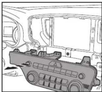
natural_image
Technical line drawing of a car interior showing structural components and frame (no text or symbols)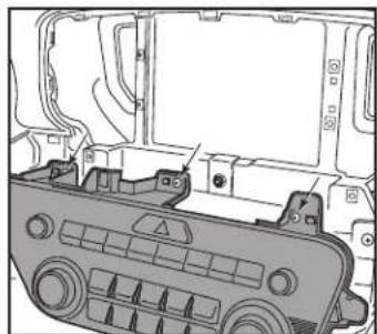
natural_image
Technical diagram of a vehicle chassis with no visible text or symbols(Figura F) (Figura H)
PREPARACIÓN DEL KIT
natural_image
Technical illustration of a car air vent assembly with a magnified inset showing internal components (no text or symbols)(Figure A)
natural_image
Technical diagram of a vehicle chassis with internal components and directional arrows indicating movement (no text or labels)(Figura C)

natural_image
Technical diagram of a mechanical component with internal channels and mounting brackets (no text or labels)(Figura D)
natural_image
Technical line drawing of a mechanical assembly with mounting holes and internal components (no text or symbols)(Figura E)
natural_image
Technical line drawing of a vehicle chassis with internal components and alignment arrows (no text or symbols)(Figura F)
ENSAMBLE DEL KIT
natural_image
Technical line drawing of a device housing with mounting holes and internal components (no text or symbols)(Figura A)
Monday - Friday: 9:00 AM - 7:00 PM
Saturday: 10:00 AM - 7:00 PM
Sunday: 10:00 AM - 4:00 PM

KNOWLEDGE IS POWER
Enhance your installation and fabrication skills to enrolling in the most recognized and respected
mobile electronics school in our industry.
Log onto www.installerinstitute.edu or call 208,670-5771 (for more information and take place
toward a better tomorrow.
