99-7627HG - Car stereo AXESS - Free user manual and instructions
Find the device manual for free 99-7627HG AXESS in PDF.

User questions about 99-7627HG AXESS
0 question about this device. Answer the ones you know or ask your own.
Ask a new question about this device
Download the instructions for your Car stereo in PDF format for free! Find your manual 99-7627HG - AXESS and take your electronic device back in hand. On this page are published all the documents necessary for the use of your device. 99-7627HG by AXESS.
USER MANUAL 99-7627HG AXESS
Installation instructions for part 99-7627H6
U.S. PATENT # D789,351
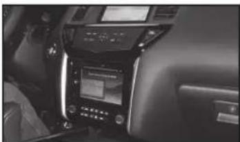
Nissan Pathfinder 2013-2016
(without NAV) (with color screen)
99-7627HG
KIT FEATURES
• ISO DIN radio provision with pocket
• ISO DDIN radio provision
- Painted to match factory components
natural_image
Interior view of a car infotainment system showing controls and display (no visible text or symbols)KIT COMPONENTS
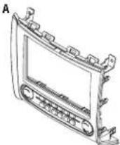
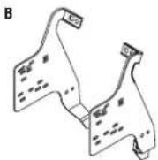
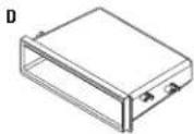
• A) Radio trim panel with climate controls • B) Radio brackets • (C) Keypad assembly • D) Pocket
• E) (4) #8 x 3/8" Phillips screws • F) (2) White panel clips • Axxess interface and harness (not shown)


WIRING & ANTENNA CONNECTIONS (sold separately)
Wiring Harness: • Included with kit Antenna Adapter: • 40-NI12
Table of Contents
Dash Disassembly 2-3
Kit Preparation....3
Kit Assembly
- ISO DIN radio provision with pocket......4
- ISO DDIN radio provision 4
Axxess interface installation....5-7
Screen Operation 8-10
TOOLS REQUIRED
- Panel removal tool
- Phillips screwdriver
• T-20 Torx driver
CAUTION: Metra recommends disconnecting the negative battery terminal before beginning any installation, unless the vehicle manufacturer recommends against so. Please check with your local Dealership for more information. All accessories, switches, climate controls panels, and especially air bag indicator lights must be connected before reconnecting the battery or cycling the ignition. Also, do not remove the factory radio with the key in the on position, or the vehicle running. It would be best to remove the key from the ignition and then wait a few seconds before removing the factory radio.

99-7627HG
Dash Disassembly
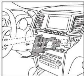
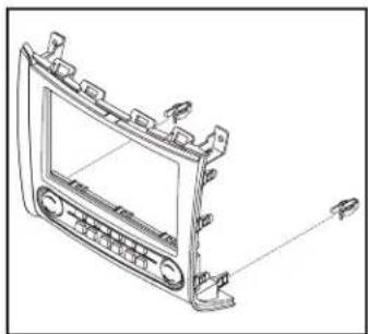
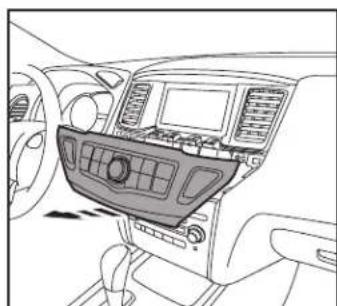
- Unclip and remove the trim panel located between the vehicle screen and control panel, and then remove (1) Phillips screw now exposed. (Figure A)
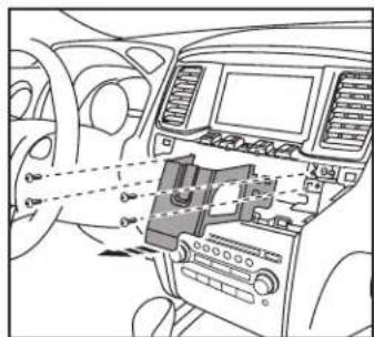
- Unclip the screen control panel, unplug the connectors, and then remove the keypad assembly from the panel. Note: The panel will be reused during kit assembly. (Figure B)
- Unscrew (4) Phillips screws securing the metal brace now exposed above the radio/climate-control panel, and then remove the brace. (Figure C)

natural_image
Top-down line drawing of a car dashboard with vent, grille, and side-mounted buttons (no text or symbols)(Figure A)

natural_image
Interior view of a car dashboard and infotainment system (no visible text or symbols)(Figure B)
text_image
Diagram of car interior showing dashboard, air intake, and control panel with Chinese labels(Figure C)
- Remove (2) Phillips screws from the top of the radio/climate-control panel. (Figure D)
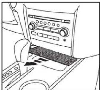
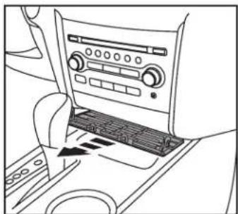
- Unclip and remove the trim panel underneath the radio/climate-control panel. (Figure E)
Continued on next page

natural_image
Top-down line drawing of a car headrest with dashboard and air vent (no text or symbols)(Figure D)
natural_image
Line drawing of a car interior showing the dashboard and air vent (no text or symbols)(Figure E)

99-7627HG
Kit PreparationDash Disassem
- Unclip and remove the radio/climate control panel. (Figure F).
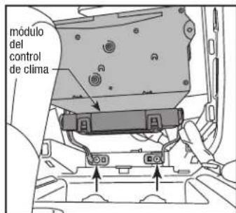
- Remove (2) Phillips screws exposed below the radio chassis, unplug the connectors, then remove the radio chassis. (Figure G)
- Remove the climate control module located under the radio chassis and set aside for kit assembly. (Figure G)
Continue to kit preparation.

natural_image
Interior view of a car dashboard with air vent and control panel (no text or symbols visible)(Figure F) (Figure A)
Kit Preparation
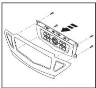
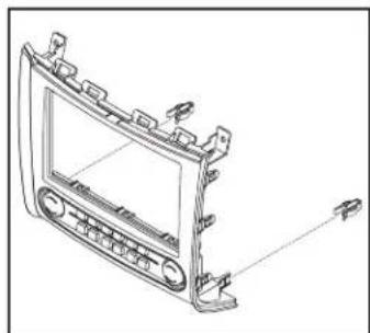
- Secure the provided keypad assembly into the screen control panel removed in step 2 of dash disassembly using the factory screws. (Figure A)
- Attach the supplied (2) white panel clips to the radio trim panel with climate controls. (Figure B)
Continue to kit assembly.
natural_image
Technical line drawing of a car air conditioner panel with control buttons and ventilation slots (no text or labels)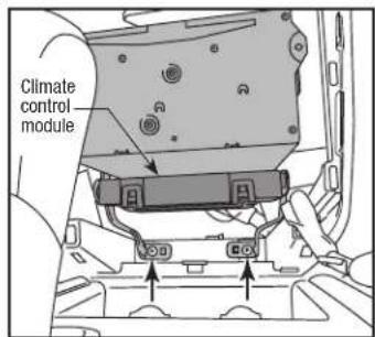
text_image
Climate control module(Figure G) (Figure B)
natural_image
Technical line drawing of a car dashboard frame with no visible text or symbols
99-7627HG
Kit Assembly
ISO DIN radio provision with pocket
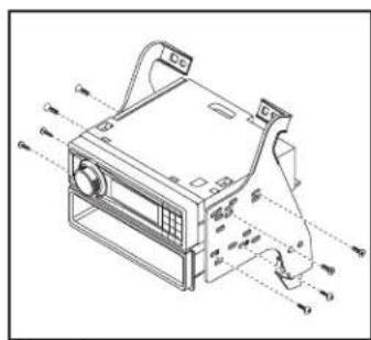
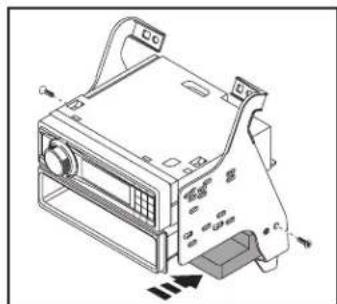
- Secure the radio brackets to the pocket using (4) #8 x 3/8" Phillips screws supplied. (Figure A)
- Remove the metal DIN sleeve and trim ring from the aftermarket radio.
- Slide the radio into the pocket/ bracket assembly using the screws supplied with the radio. (Figure A)
- Mount the climate control module to the bracket assembly below the radio and pocket, using the hardware removed during disassembly. (Figure B)
Continue to Axxess Interface Installation
natural_image
Technical line drawing of a computer case with ventilation slots and control panel (no text or symbols)(Figure A)
ISO DDIN radio provision
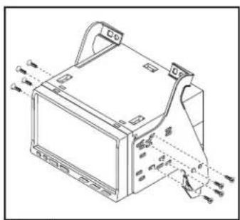
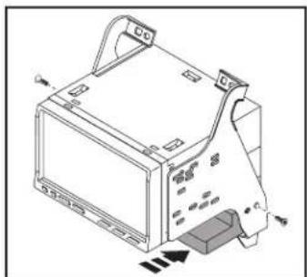
- Attach the radio brackets to the radio using the screws supplied with the radio. (Figure A)
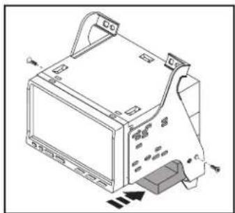
- Mount the climate control module to the bracket assembly below the radio, using the hardware removed during disassembly. (Figure B)
Continue to Axxess Interface Installation
natural_image
Technical line drawing of a mechanical device with mounting brackets and internal components (no text or symbols)(Figure A)

natural_image
Isometric line drawing of a computer monitor with ventilation slots and control knobs (no text or symbols)(Figure B)
natural_image
Technical line drawing of a computer monitor with ports and control panel (no text or symbols)(Figure B)
Axxess Interface Installation
FEATURES
- Retains factory screen
• Retains factory back up camera - Retains factory AUX-IN
• Retains personalization features - Ability to add aftermarket backup camera or additional video input
- Works in amplified or non-amplified models
- Prewired ASWC-1 harness included (ASWC-1 sold separately)
INTERFACE COMPONENTS
- Axxess Interface
- 7627 harness
• 16, 20, and 32-pin to 12 and 22-pin harness
• 14-pin to 4, 16, and 18-pin extension harness
• 14-pin to 14-pin extension harness wrapped in black tape
• 12-pin harness with (4) RCA jacks
• 20-pin to 24-pin extension harness wrapped in black tape
TOOLS REQUIRED
• Cutting tool • Crimping tool • Tape
- Connectors (example: butt-connectors, bell caps, etc.)
Connections to be made
From the 7627 harness to the aftermarket radio:
- Connect the Black wire to the ground wire.
- Connect the Yellow wire to the battery wire.
- Connect the Red wire to the accessory wire.
- Connect the Orange wire to the illumination wire. (If the aftermarket radio has no illumination wire, tape off the Orange wire).
- Tape off and disregard the White/Blue wire, it will not be used in this application.
The following (2) wires are for an aftermarket multimedia/navigation radio that provide these wires (if not required, tape them off and disregard them):
- Connect the Blue/Pink wire to the speed sense wire (if applicable).
- Connect the Green/Purple wire with a female bullet connector to the reverse wire (if applicable).
- Connect the Green/Purple wire with a male bullet connector, to the Green/Purple wire with a female bullet connector. Only connect this wire if the Green/Purple wire with a male bullet connector has a wire populated on the factory side.
Connections to be made
For models without a BOSE sound-system:
- Connect the White wire to the left front positive speaker output.
- Connect the White/Black wire to the left front negative speaker output.
- Connect the Gray wire to the right front positive speaker output.
- Connect the Gray/Black wire to the right front negative speaker output.
- Connect the Green wire to the left rear positive speaker output.
- Connect the Green/Black wire to the left rear negative speaker output.
- Connect the Purple wire to the right rear positive speaker output.
- Connect the Purple/Black wire to the right rear negative speaker output.
For models with a BOSE sound-system:
- Tape off and disregard the White, White/Black, Gray, Gray/Black, Green, Green/Black, Purple, Purple/Black wires, they will not be used in this application.
- If you wish to retain the factory AUX-IN jack, connect the Red and White RCA jacks labeled "AUX input", to the AUX-IN jack (if applicable).
- Tape off and disregard the Red and White RCA jacks labeled "FROM DVD", they will not be used in this application.
- Tape off and disregard the Yellow RCA jack labeled FROM DVD, it will not be used in this application.
- If you wish to add an aftermarket backup camera or external video source, connect the Yellow RCA jack labeled "Backcam" into the desired source.
• 12-pin pre-wired ASWC-1 harness:
This harness is to be used along with the optional ASWC-1 (not included) to retain steering wheel audio controls. If the ASWC-1 is not being used, disregard this harness. If it will be used, please refer to the ASWC-1 instructions for radio connections and programming.
Note: Disregard the harness that comes with the ASWC-1.
Note: Disregard the RCA jack labeled "FROM DVD", it will not be used in this application.
From the 12-pin harness with (4) jacks to the aftermarket radio (for BOSE sound-systems only):
- Connect the Blue/White wire to the amp turn on wire (this wire must be connected to hear sound from the factory amplifier).
- Connect the White, Gray, Green, and Purple RCA jacks to the audio outputs. White is left front, Gray is right front, Green is left rear, and Purple is right rear.

99-7627HG
Installing the 99-7627 Final Assembly
Concerning the radio trim panel with climate controls and the keypad assembly. The radio trim panel with climate controls has (2) connectors:
- Connect one end of the 14-pin to 14-pin extension harness wrapped in cloth tape, to the connector on the left side (driver's side of the vehicle as you are looking at the front of the panel). The other end will connect to the Axxess interface.
- Connect the 14-pin connector of the 14-pin to 4, 16, and 18-pin extension harness, to the connector on the right side (passenger side of the vehicle as you are looking at the front of the panel). The 18-pin connector will connect to the keypad assembly. The 4 and 16-pin harness will connect to the (2) harnesses previously removed from the radio/climate-control panel removed in dash disassembly.
- Connect the 20-pin connector of the 20-pin to 24-pin extension harness wrapped in black tape, to the 20- pin harness removed from the factory radio/climate-control panel. The 24-pin connector will then connect into the Axxess interface.
- Connect the 22-pin harness of the 7627 harness into the Axxess interface.
- With the key in the off position, connect the 16, 20, and 32-pin harness of the 7627 harness into the vehicle.
Attention: The 16-pin harness must be connected for the factory back-up camera to function. There are (2) 16-pin connectors available in the dash. Use the 16-pin connector that is grouped with the factory radio connectors; the one removed from the radio chassis in step 7 of dash disassembly.
- Locate the factory antenna connector in the dash, and complete all necessary connections to the radio and climate control module. Metra recommends using the proper mating adapter from Metra. Re-connect the negative battery terminal, then test the radio and 99-7627 for proper operation.
Note: If using the ASWC-1 (sold separately), connect it after you test the 99-7627B, with the key in the off position.
- Mount the completed assembly into the dash using the 99-7627 radio trim panel with climate controls, and then reassemble the dash in reverse order of disassembly.

99-7627HG
Screen Operation
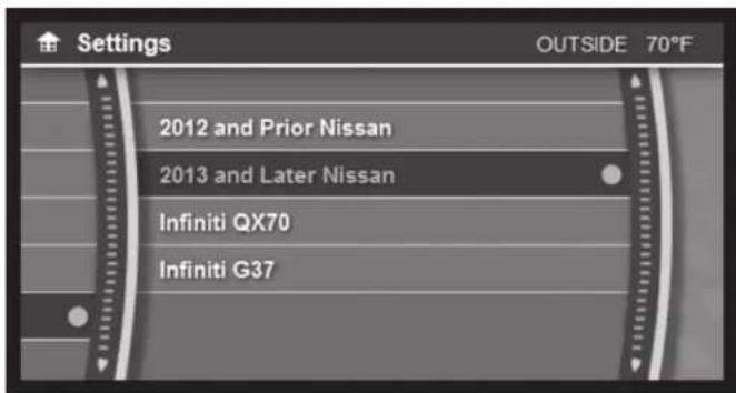
Vehicle selection:
text_image
Settings OUTSIDE 70°F 2012 and Prior Nissan 2013 and Later Nissan Infiniti QX70 Infiniti G37- The included interface is designed to auto-detect what vehicle it is in. In the settings menu, there is an option of forcing the vehicle type to the interface.
- Go to - SETTINGS>MISCELLANEOUS>SELECT VEHICLE
Settings:

text_image
Settings OUTSIDE 70°F Display Clock Comfort & Conv. Units MiscellaneousAll button functions are retained and are controlled in the same manner that the factory buttons were controlled. (example: Tire Pressure, Fuel Economy, Brightness, Clock Setting, etc)

99-7627HG
Screen Operation
Backup camera/AUX video settings:

text_image
Settings OUTSIDE 70°F Camera Input Reverse Cam Lines Select Car System Information- Camera Input
- Go to – SETTINGS> MISCELLANEOUS>CAMERA INPUT> AFTERMARKET CAMERA
- The factory equipped back-up camera will continue to function without any additional wiring or programming. The interface is shipped in this mode.
- If the vehicle does not come equipped with a factory backup camera, an aftermarket camera can be used. If an aftermarket camera is installed, the settings will need to be changed to reflect this.
Note:
- The aftermarket camera will be activated by the vehicle's reverse signal, which is sent to the Axxess interface.
- The camera input can also be used as an AUX video in. The blank button on the far right of the radio trim panel with HVAC controls will toggle the AUX video on or off.
Note: The AUX video will only work with the vehicle in PARK.
- Reverse Camera Lines
- Go to – SETTINGS>MISCELLANEOUS> REVERSE CAM LINES
- On or off
Note: By default, the back-up lines for the camera are set to off.

99-7627HG
Screen Operation Updating the 99-7627
System INFO:

text_image
i System Information OUTSIDE 70°F APP: OS: PIC: UI: v0.1.4- To access the current software of this product after it has been installed.
- Go to - SETTINGS>MISCELLANEOUS>SYSTEM INFORMATION
-
Please have this information available when calling tech support for assistance.
-
Download and install the WebXXpress software update from axxessinterfaces.com.
- Connect the USB-MINI-CAB update cable (sold separately) between the 99-7627 and the computer. The cable will connect into the port on the rear of the kit labeled "A".
Note: The 99-7627 will need to be powered up to be updated.
- From the Start Menu of the computer, click on "USB Bootloader", and then click "Update Board". The software will begin to download at this point.
Note: If 30 seconds elapses before you finish this step, you will need to remove power from the 99-7627, then reapply power, and then start the update process again.
Note: Please note which firmware downloaded to the interface. This will help in troubleshooting, if need be.
Metra
99-7627HG

Installation instructions for part 99-7627HG

IMPORTANT
If you are having difficulties with the installation of this product, please call our Tech Support line at 1-800-253-TECH. Before doing so, look over the instructions a second time, and make sure the installation was performed exactly as the instructions are stated. Please have the vehicle apart and ready to perform troubleshooting steps before calling.

KNOWLEDGE IS POWER
Enhance your installation and fabrication skills by enrolling in the most recognized and respected mobile electronics school in our industry. Log onto www.installerinstitute.com or call 800-354-6782 for more information and take steps toward a better tomorrow.

Metra recommends MECP certified technicians
Nissan Pathfinder 2013-2016
natural_image
Interior view of a car dashboard with digital display and control panel (no visible text or symbols)COMPONENTES DEL KIT
natural_image
Front view of a car dashboard with ventilation grilles and directional arrows (no text or symbols)(Figura A)
natural_image
Interior view of a car dashboard and infotainment system (no visible text or symbols)(Figura B)
natural_image
Interior view of a car dashboard with visible controls and wiring (no text or symbols)(Figura C)
natural_image
Top-down line drawing of a car headrest with dashboard and air vent (no text or symbols)(Figura D)
natural_image
Line drawing of a car air intake system with control panel and fan (no text or symbols)(Figura E)

99-7627HG
natural_image
Interior view of a car head panel showing dashboard, air vent, and control buttons (no text or symbols)(Figura F)
natural_image
Technical line drawing of a car air conditioner panel with control buttons and indicator lights (no text or symbols)(Figura A)
natural_image
Line drawing of a car dashboard frame with control panel and sensor components (no text or symbols)(Figura B)

99-7627HG
Ensamble del kit
natural_image
Technical line drawing of a computer air conditioner unit with control panel and ventilation slots (no text or labels)(Figura A)
natural_image
Isometric line drawing of a computer monitor with ports and buttons, no text or symbols present(Figura B)
natural_image
Technical line drawing of a mechanical device with mounting brackets and internal components (no text or symbols)(Figura A)
natural_image
Technical line drawing of a computer monitor with ports and ventilation slots (no text or symbols)(Figura B)