RVCLR-68A - Rear Camera CRUX - Free user manual and instructions
Find the device manual for free RVCLR-68A CRUX in PDF.

User questions about RVCLR-68A CRUX
0 question about this device. Answer the ones you know or ask your own.
Ask a new question about this device
Download the instructions for your Rear Camera in PDF format for free! Find your manual RVCLR-68A - CRUX and take your electronic device back in hand. On this page are published all the documents necessary for the use of your device. RVCLR-68A by CRUX.
USER MANUAL RVCLR-68A CRUX
Rear-view camera-input and
video-in-moon
for Landrover
touch-screen navigaon systems
model 2010-2011
Only for vehicles WITHOUT factory rear-view camera
Contents
- Prior to installaon
1.1. Delivery contents
1.2. Check compatibility of vehicle and accessories
1.3. Seng the Dip-switches of the CAN-Box
1.4. Pin-assignments
-
Connecon schema
-
Installaon
3.1. Interconnecng CAN-box, harness and radio module
3.2. Connecon to rear-view camera
-
Acvaon of the video-in-moon funcon
-
Specicaons
-
Technical support
Legal Informaon
By law, watching moving pictures while driving is prohibited, the driver must not be distracted. We do not accept any liability for material damage or personal injury resulting, directly or indirectly, from installaon or operaon of this product. This product should only be used to display xed menus or rear-view-camera video when the vehicle is moving, for example the MP3 menu for DVD upgrades.
1. Prior to installaon
Read the manual prior to installaon. Technical knowledge is necessary for installaon. The place of installaon must be free of moisture and away from heat sources.
1.1. Delivery contents
Take down the SW-version and HW-version of the interface boxes, and store this manual for support purposes.

text_image
CAN-box HW___ SW___ CRUX Sightline REAR-VIEW INTEGRATION REAR-VIEW INTEGRATION MODULE Harness Adapter1.2. Check compatibility of vehicle and accessories
Requirements
Vehicle 2010 - 2011 Land Rover Discovery (L319)
2010 - 2011 Range Rover Sport (L320)
2010 - 2012 Range Rover Vogue (L322)
Navigaon Touch-screen navigaon system- version 2
1.3. Seng the dip switches of the CAN-box
| Vehicle/ navigaon | Dip 1 | Dip 2 | Dip 3 | Dip 4 | Dip 5 | Dip 6 |
| Video-in-moon permanent | ON | ON | OFF | OFF | ON | ON |
| Video-in-moon selecve* | OFF | ON | OFF | OFF | ON | ON |
* With dip1 to OFF the included green cable is used to acvate the video-in-moon funcon
Note: Dip switch funcons
Dip 1 – acvaon TV-free
Dip 2 – rear-view camera exisng
Dip 3 – TV icon simulaon
Dip 4 – no funcon
Dip 5 – terminaon resistor CAN-Bus
Dip 6 – terminaon resistor CAN-Bus
Seng dip 2 to ON codes the factory rear-view camera input which is located on the brown Fakra male connector of the factory monitor. When reverse gear is engaged, the navigaon will automacally switch to this input. On vehicles with factory rear-view camera set Dip 2 to ON, too.
1.4. Pin-assignments
Pin-assignment vehicle connector Range Rover Vogue
| Cable color | Assignment |
| ●○ Yellow/White | CAN-HIGH Pin 9 |
| ●● Yellow/Blue | CAN-LOW Pin 10 |
Pin assignment vehicle connector Sport & Discovery
| Cable color | Assignment |
| ●○ Yellow/White | CAN-HIGH |
| ●Yellow | CAN-LOW |
No liability for vehicle wire colors and pin denion! Possible changes by the vehicle manufacturer. The given informaon must be veried by the installer.
Pin-assignment of the CAN-Box (Molex 8pin)
| Cable color | Pin-No. | Assignment |
| Yellow | Pin 4 | CAN-HIGH – conncon to the head-unit |
| Blue | Pin 3 | CAN-LOW – conncon to the head-unit |
| Yellow/Black | Pin 8 | CAN-HIGH – conncon to the vehicle |
| Blue/Black | Pin 7 | CAN-LOW – conncon to the vehicle |
| Red | Pin 1 | +12V permanent |
| Black | Pin 5 | Ground |
| Green | Pin 6 | Acvaon of the video-in-moon funcon (+12V = TV-free acvated) |
| White | Pin 2 | Trigger output (+12V DC 500mA) |
Assignment 6pin male port of the monitor
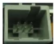
Pin 2: Video-signal rear-view camera
Pin 5: Video-signal ground rear-view camera
2. Connecon schemac

flowchart
graph TD
    A["Rear-view camera"] --> B["Adapter"]
    B --> C["6pin male port of the monitor"]
    C --> D["Female system of vehicle harness to radio module"]
    D --> E["CAN-box"]
    E --> F["Rear side of radio module"]
    F --> G["Harness"]
    G --> H["Computer with cable"]
3. Installaon
Switch o ignion and disconnect the vehicle's baery! If according to factory rules disconnecng the baery has to be avoided, it is usually sucient to put the vehicle in sleep-mode. In case the sleep-mode does not show success, disconnect the baery with a resistor lead.
Place of installaon is on rear of the radio module and behind the factory navigaon monitor. On Range Rover Vogue the radio module is a hide-away box which is located behind the glove box, on Range Rover Sport and Discovery 4 the radio module is located behind the factory navigaon monitor.
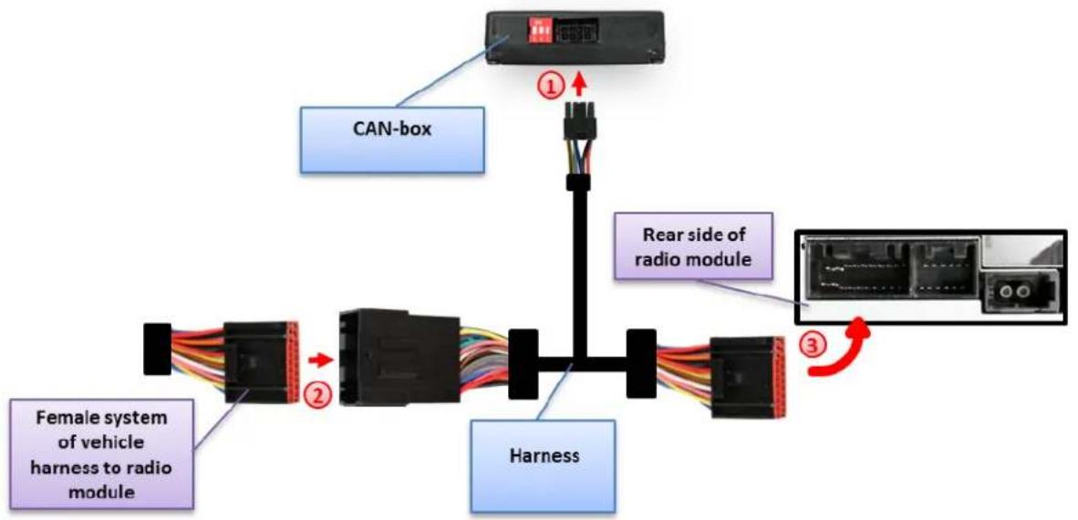
3.1. Interconnecng CAN-Box, harness and radio module
flowchart
graph TD
    A["CAN-box"] --> B["Female system of vehicle harness to radio module"]
    B --> C["②"]
    C --> D["①"]
    D --> E["Rear side of radio module"]
    E --> F["③"]
    F --> G["Harness"]

Connect female 8pin Molex connector of harness to male 8pin Molex connector of CAN-box.

Transfer female system-connector of vehicle harness from rear of radio module into male system-connector of harness.

Plug female system-connector of into male socket on the rear of radio module.
3.2. Connecons to rear-view camera
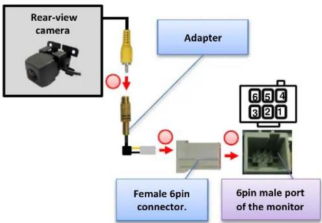
flowchart
graph TD
A["Rear-view camera"] --> B["Adapter"]
B --> C["Female 6pin connector."]
C --> D["6pin male port of the monitor"]
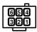
D --> E["6-pin 3 2 1"]
E --> F["6 pin 5 4"]

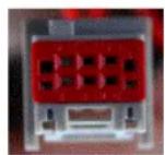
Pin colored video-signal (black video-signal ground) with bare contact of adapter into pin 2 (pin 5) of the female grey-red 6pin connector. Use red front is to lock the pins in the connector.

Connect female grey-red 6pin connector to 6pin male port of the monitor.

Connect the video RCA of the rear-view camera to female RCA connector of adapter.
Note: Only compatible with NTSC-cameras.
If the factory Adventure-camera is installed, there is already a female grey-red 6pin connector on the factory vehicle harness which is connected to the male 6pin port on the backside of the factory monitor. In this case pin the two bare contacts into the female grey-red 6pin connector of the vehicle harness instead of the supplied one.
4. Acvaon of the video-in-moon funcon
The video-in-moon can be acvated and deactivated by Dip 1 or alternatively by the included loose green cable in conneccon with a switch (not included in delivery).
Video-in-moon permanent
With dip1 to ON the video-in-moon funcon is acvated permanently without disturbing the navigaon performance.
Video-in-moon selecve
With dip1 to OFF the included green cable is used to acvate the video-in-moon funcon.
Connect a switch to the green cable and connect the green cable to +12V ACC.
• +12V = TV-Free is acvated
• 0V = TV-Free is not acvated
Note: The loose white cable is not required and must be isolated.
5. Specicaons
Operaon voltage 10.5 – 14.8V
Stand-by power drain <2mA
Operaon power drain \~60mA
Power consumpon \~0,08W
Temperature range -30°C to +80°C
Weight 44g
Measurements (box only) W x H x D 70 x 20 x 47 mm/ 76 x 27 x 54 mm
text_image
CE ===12V DC6. Technical support
Crux Interfacing Soluons
phone 1818-609-9299
email support@cruxinterfacing.com