RVCCH-75R - Rear Camera CRUX - Free user manual and instructions
Find the device manual for free RVCCH-75R CRUX in PDF.

User questions about RVCCH-75R CRUX
0 question about this device. Answer the ones you know or ask your own.
Ask a new question about this device
Download the instructions for your Rear Camera in PDF format for free! Find your manual RVCCH-75R - CRUX and take your electronic device back in hand. On this page are published all the documents necessary for the use of your device. RVCCH-75R by CRUX.
USER MANUAL RVCCH-75R CRUX
- Activates Mygig radio for enabling video features
• Tailgate handle camera included - Interface includes Audio / Video Input to connect an extra A/V source
- Automatically switches to Rear-view when car is in Reverse mode
- Supports vehicles with manual transmission but does not supply +12V Reverse Trigger. Camera power must be tapped from the +12V reverse light wire instead
- Plug & Play Installation
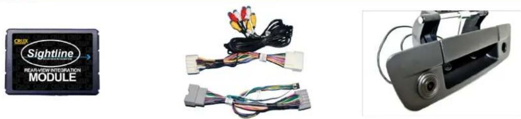
PARTS INCLUDED:
natural_image
Three electronic components: a Sightline module with visible wiring, connected cables, and a camera frame (no text or symbols on components)RVCCH-75R Module RVCCH-75R Harness Tailgate Handle Camera
INSTALLATION DIAGRAM:

flowchart
graph TD
    A["TO RADIO"] --> B["Gray 22-PIN (MALE)"]
    A --> C["WHITE 22-PIN (MALE)"]
    A --> D["Gray 22-PIN (FEMALE)"]
    A --> E["WHITE 22-PIN (FEMALE)"]
    B --> F["A/V OUT"]
    B --> G["A/V INPUT"]
    C --> H["RED Wire Tape Off (Not Used)"]
    C --> I["To Source Ground (ground wire) (not chassis ground)"]
    D --> J["Regulator"]
    E --> K["20 Ft. Coax Cable"]
    L["8-Pin Molex"] --> M["Tap Green wire to +12V ACC for non permanent VIM. Set DIP 1 to OFF. (toggle switch not included)"]
    M --> N["To +12V ACC"]
    O["DIP SWITCH"] --> P["LED RED = Power ON Status LED BLUE = Data Bus ON Status"]
    Q["White Wire Parking Guideline"] --> R["Regulator"]
    S["White Wire* (Camera Power Output +12V 250mA)"] --> T["White Wire Wire*"]
    U["*Note that the white wire does not supply ReverseTrigger on Manual Transmission and should be insulated .Camera power must be connected to factory reverse light wire instead."] --> V["Output"]
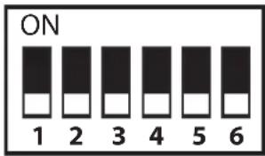
DIP SWITCH SETTINGS:
DIP SWITCH FUNCTIONS:
DIP 1 = Video in Motion Activation ON (permanent VIM) / OFF (use Green wire)
DIP 2 = Rear View Camera ON / OFF
DIP 3 = Set to OFF
DIP 4 = Set to OFF
DIP 5 = CAN Termination Radio Side*
DIP 6 = CAN Termination Car Side*
*DIP 5 & 6
If the radio is having turn-on issues, please try the following:
Attempt 1: Set 5 & 6 to ON
Attempt 2: Set 5 to ON and 6 to OFF
Attempt 3: Set 5 to OFF and 6 to ON
text_image
ON 1 2 3 4 5 6INSTALLATION INSTRUCTIONS:
INSTALLING THE RVCCH-75R INTERFACE
- Remove the factory radio to gain access to the factory connectors.
- Plug in the t-harness with WHITE and GRAY connectors. (See wiring diagram on page 1)
- Set the proper DIP Switch settings on the RVCCH-75R module. (See chart above)
- Use the WHITE 12V Reverse Output wire to power the camera (see wiring diagram on page 1). DO NOT connect the red power wire, near the camera, to the reverse light and insulate this red wire to avoid from shorting. If the vehicle has a manual transmission, the camera power must be tapped to the +12V reverse light wire instead. In this case the WHITE 12V Reverse Output wire is not used and should be insulated to avoid from shorting.
- Plug in the AV source and test for functionality.
- Proceed to installing the tailgate handle camera.
INSTALLING THE CDR-02 CAMERA
- Remove the OE tailgate handle.
- Remove the OE lock cylinder and install in the CDR-02 camera housing.
- Install the new tailgate handle and run the cables to the radio.
- Remove the factory radio to gain access to the factory connectors.
- Route the wires towards the radio and make the power and video connections. For powering up the camera, use the 12V OUTPUT (White Wire). (See Wiring Diagram on page 1)
- Connect the camera ground wire to chassis ground. If video noise is present, we recommend grounding the camera directly to the BLACK wire on the RVCCH-75D T-harness.
- The CDR-02 has a built-in parking guide lines option and is defaulted to ON from the factory. To turn OFF the parking guide lines, cut the thin WHITE wire located on the camera cable 4 feet from the camera. Unplug the barrel connectors on the cable for 5 seconds. Align the arrows on the barrel connectors and firmly plug them together.
- Plug in the Yellow male RCA from the camera cable to the Yellow female RCA of the t-harness with white connectors.
- Put the gear in reverse to test the camera before re-installing the radio.
LED INFORMATION:
The RVCCH-75R module has 2 LEDs on the side of the Molex connector that confirms its functionality as follows:
RED LED: ON = Confirms Power
BLUE LED: PULSING = No BUS, Pending Data
OFF = Complete Power Down
SOLID = BUS Recognized

2 of 3
rev.092220
PARKING GUIDE LINES:
The parking lines are there to assist you while reversing. To deactivate the parking lines simply cut the WHITE loop wire located near the 4 pin camera connector and cycle the camera power.
What the Lines mean:
Green Line: CLEAR
Yellow Line: GETTING CLOSE
Red Line: WARNING - VERY CLOSE

text_image
GREEN YELLOW REDSWITCHING SOURCES:
VES will be your source for the AV Input.

To access the VES button, press the RADIO/MEDIA button on the left side of the radio. The VES button is only active after the interface is properly installed.
VEHICLE APPLICATIONS:
RAM
2009 - 2012 RAM Truck
COMPATIBLE RADIO:
MyGig Radio
(HARD DISC DRIVE or HARD DRIVE printed on the lower right hand side of radio face)

natural_image
Interior view of a car dashboard with a digital navigation screen displaying map and traffic flow (no visible text or symbols)