
KAWLMFM43MA - Microwave Kogan - Free user manual and instructions
Find the device manual for free KAWLMFM43MA Kogan in PDF.

| Product Type | Tilt, Extendable, Full Motion Wall Mount |
| Compatible TV Sizes | Suitable for 134''-3" TVs (actually 134-3? likely 13-43 inches) |
| Maximum Load Capacity | 20 kg |
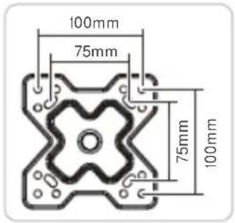
| VESA Compatibility | 75x75, 100x100, 100x200, 200x100, 200x200 mm |
| Wall Mount Dimensions | Full extension: not specified; allow extra space |
| Weight of Mount | Approx. 1.5 kg (estimate based on similar models) |
| Material | Steel with painted finish |
| Color | Black (common) |
| Tilt Range | Adjustable vertical angle (via loosening lower screws) |
| Rotation (Swivel) | Adjustable via loosening central nuts |
| Horizontal Movement | Freely positionable without tools |
| Extension Arm Length | Full motion: extends from wall |
| Installation Tools Required | Phillips screwdriver, stud finder, pencil, drill, wrench |
| Included Components | Wall mount bracket (x1), VESA extension arms (x4), spirit level (x1), M5x12 bolts (x4), M5 nuts (x4), spanner (x1), M6x14 screws (x4), M8x20 screws (x4), M-C spacers (x4), ST6.3x55 screws (x3), wall anchors (x3), washers (x3) |
| Safety Gear Required | Safety glasses, gloves recommended |
| Indoor Use Only | Yes |
| Maintenance | Check security every 3 months |
| Warranty | Refer to Kogan support |
| Spare Parts Availability | Contact Kogan for replacement parts |
| Reparability | DIY not recommended; contact support |
Frequently Asked Questions - KAWLMFM43MA Kogan
User questions about KAWLMFM43MA Kogan
0 question about this device. Answer the ones you know or ask your own.
Ask a new question about this device
Download the instructions for your Microwave in PDF format for free! Find your manual KAWLMFM43MA - Kogan and take your electronic device back in hand. On this page are published all the documents necessary for the use of your device. KAWLMFM43MA by Kogan.
USER MANUAL KAWLMFM43MA Kogan
TILT EXTENDABLE FULL MOTION WALL MOUNT
(SUITABLE FOR 134'3- "TVS)
KAWLMFM43MA
SAFETY & WARNINGS
- Read the entire user guide before you start installation and assembly. If you have any questions regarding any of the instructions or warnings, contact help.Kogan.com for support.
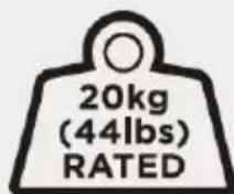
- CAUTION: Use with products heavier than the rated weights indicated may result in instability causing possible injury.
- Safety gear and quality tools must be used.
- Make sure that the supporting surface will safely support the combined weight of the equipment and all attached hardware and components.
- Use the mounting screws provided and DO NOT OVER TIGHTEN mounting screws.
- This product contains small items that could be a choking hazard if swallowed. Keep these items away from children.
- This product is intended for indoor use only. Using this product outdoors could lead to product failure and personal injury.
- Soundbar and TV models shown in images are for reference only and may differ to your own. Soundbar and TV are sold separately.
- Never exceed the maximum load capacity of 20kg or it may result in product failure or personal injury.
- IMPORTANT: Ensure that you have received all parts listed on the components page prior to installation or disposing of any packaging. If any parts are missing or faulty, contact help.kogan.com for assistance.
- MAINTENANCE: At regular intervals, check that the product is secure and safe to use (at least every three months).
VESA Compatible 75x75 100x100 100x200 200x100 200x200

COMPONENTS

A Bracket / wall mount (x1)

B VESA mount extension arms (x4)

C Spirit level (x1)
D Extension arm bolt
M5x12 (x4)

E Extension arm nut (x4)

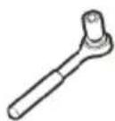
F Spanner (x1)
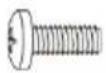
M-A Screw M6 x 14 (x4)
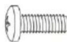
M-B Screw
M8 x 20 (x4)

M-C Spacer (x4)
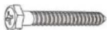
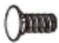
W-A Screw
ST6.3 x 55 (x3)
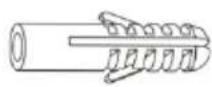
W-B Wall anchors
ø10 x 45 (x3)

W-C Washer (x3)
Tools required for installation (not supplied)
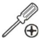
Phillips head
screwdriver

Stud finder
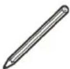
Pencil
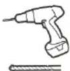
Drill
Wrench
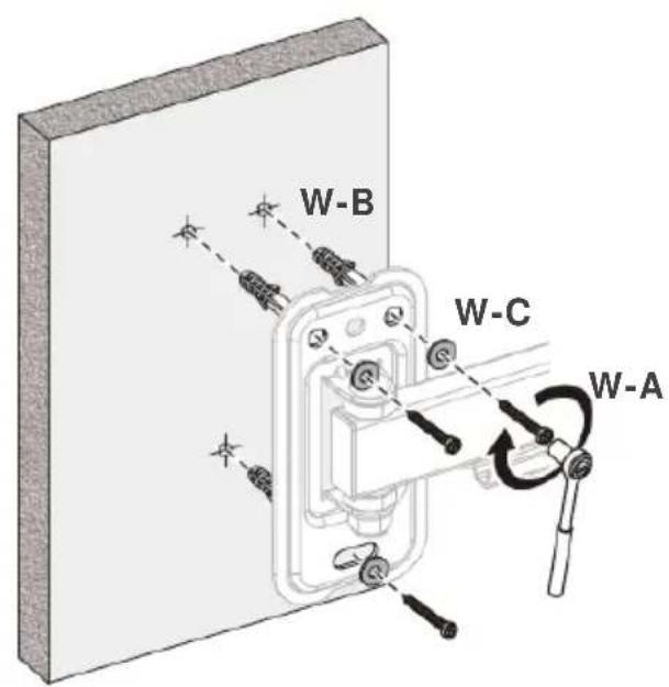
INSTALLING MOUNT TO WALL
Step 1:
Extend the Bracket / wall mount (A) out to full length.

Step 2:
Using a Phillips head screwdriver (not supplied), unscrew and remove the 3mm screws attaching the arm wall mount. Retain these screws nearby for later use.

Step 3:
- Using a pencil, and the Spirit level (C), mark the desired position for the mount on your wall, using the wall mount to serve as a template for the hole positions. If mounting on dry wall or plaster-board, use a stud finder first to check positions of wall studs and ensure the position is free from electrical wiring.
• Using a drill, create the pilot holes.
Note: Pencil, stud finder and drill not supplied.
Drywall / plaster: Use a 4.5mm or 3/16" drill bit, drilling 55mm deep.
Masonry / concrete: Use a φ drilling 60 mm deep.

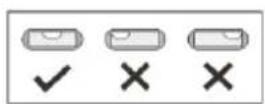
Note: When using the spirit level, ensure the bubble is centred as per the image shown.
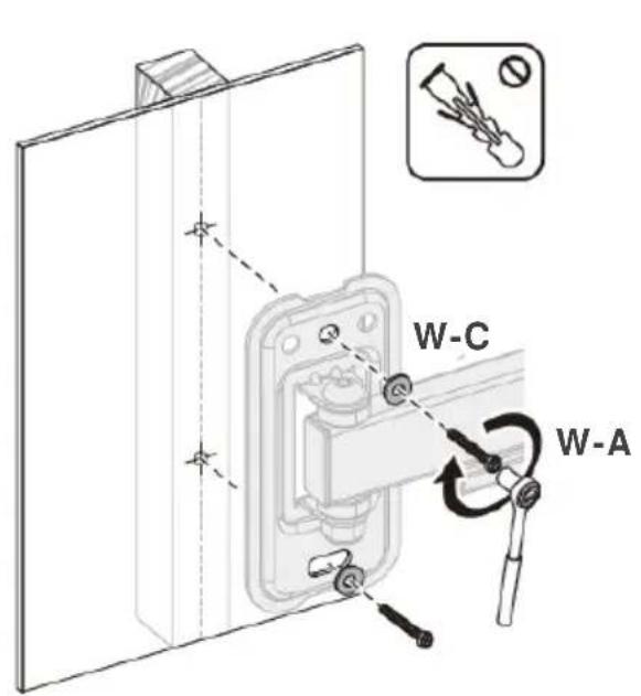
Step 4:
Drywall / plaster: Position the wall mount in line with the pilot holes and secure to the wall using washers (W-C) and ST6.3x55 screws (W-A). Do not use the wall anchors.
Masonry / concrete: Insert wall anchors (W-B) into the drilled holes. Position the wall mount in line with the holes and secure to the wall using washers (W-C) and ST6.3x55 screws (W-A).
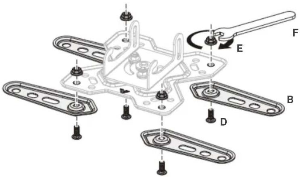
INSTALLING BRACKET TO TV
Step 1:
VESA: 75x75; 100x100: Extension arms (B) are not required.
VESA: 100x200; 200x100; 200x200: Attach the Extension arms (B) to the bracket using the bolt and nut set (D, E), tightening with the included spanner (F).
VESA: 75x75 & 100x100
VESA: 100x200

VESA: 200x100

VESA: 200x200


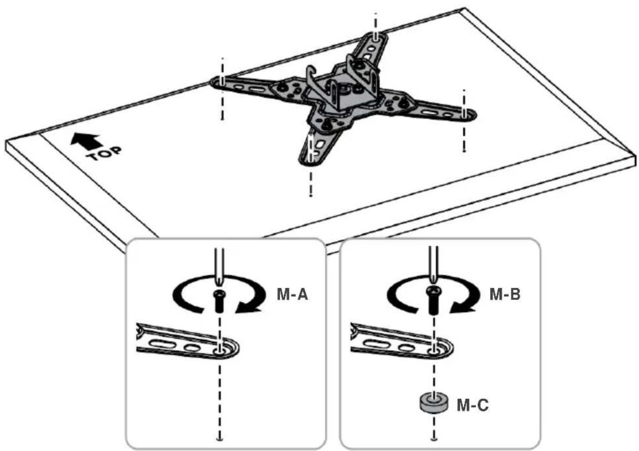
Step 2:
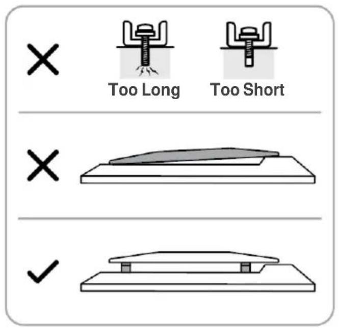
- With the extension arms successfully fitted (if required), align the bracket with your TV's VESA holes and secure using supplied screws (M-A or M-B) (depending on required length).
- Check if spacers (M-C) are required to ensure correct length of screw, as per the below image. Failure to follow this step may result in damage to your TV or wall mount.
SECURING TV TO MOUNT
Step 1:
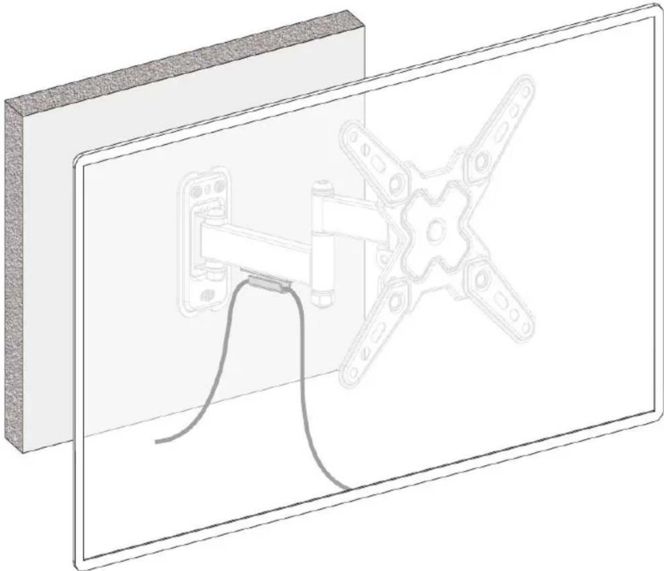
- With the top 2 screws (from Step 2) loosely in place, hook the TV with bracket installed onto the wall mount arm. Note: 2 people should carry the TV to prevent damage.
- Once in place, attach the lower 2 screws, then tighten all 4. Do not overtighten.

Step 2:
Add the TV's cables to the cable management clip.
ADJUSTMENTS
To adjust the TV vertical angle, loosen the lower 2 screws and move the bracket into the desired position before retightening. Do not overtighten.
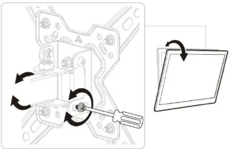
To rotate the TV, loosen the 2 central nuts and move the bracket into the desired position before retightening. Do not overtighten.
Note: Horizontal angles can be freely positioned without adjusting fasteners.
![graph TD A[" gears shift"] --> B[" rotational motion"] B --> C["转向旋转"] C --> D["返回按钮"]](/content/2026/06/1226222/images/7842e2b59a2a03dd811ab2aa25dd1527b4180d1b39c1683f80b1790ed6cb9fbd.jpg)
Need more information?
We hope that this user guide has given you the assistance needed for a simple set-up.
For the most up-to-date guide for your product, as well as any additional assistance you may require, head online to help.kogan.com
kogan.com


Brand : Kogan
Model : KAWLMFM43MA
Category : Microwave