99-3410 - Car accessory Metra - Free user manual and instructions
Find the device manual for free 99-3410 Metra in PDF.

User questions about 99-3410 Metra
0 question about this device. Answer the ones you know or ask your own.
Ask a new question about this device
Download the instructions for your Car accessory in PDF format for free! Find your manual 99-3410 - Metra and take your electronic device back in hand. On this page are published all the documents necessary for the use of your device. 99-3410 by Metra.
USER MANUAL 99-3410 Metra
▶ Shaft and DIN unit provisions
Equalizer provisions
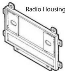
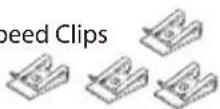
KIT COMPONENTS
natural_image
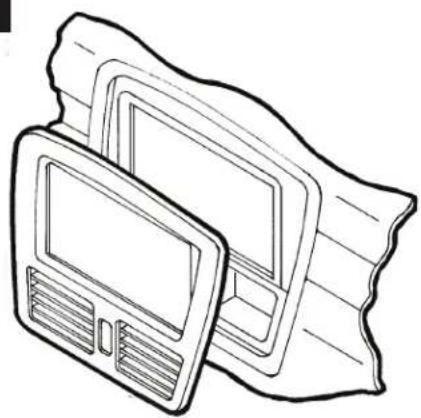
Technical line drawing of a radio housing component (no text or symbols)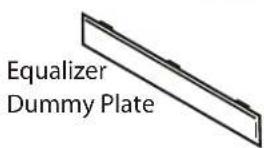
text_image
Equalizer Dummy Plate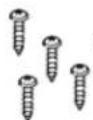
(4) #8 x 1" Phillips Pan-Head Screws
(4) Speed Clips
TOOLS REQUIRED
Phillips screwdriver

Cutting tool

Wrench

99-3410 AW -341GO DW -3410
INSTALLATION INSTRUCTIONS
APPLICATIONS
CAR
PAGE
CHEVROLET
Tracker 1998-04....1
GEO
Metro 1992-94....1
Tracker 1992-97....1
SUZUKI
Aerio 2003.... 2
Esteem 1995-03....2
Sidekick 1992-98....1
Swift 1992-94....1
Vitara series 1999-04....1
WIRING AND ANTENNA CONNECTIONS (Sold Separately) Harness:
- Please visit www.metraonline.com for specific interface applications
Antenna Adapter:
• 40-GM10 - GM antenna adapter 88-up

KOWER NOWLEDBGE IS
Enhance your installation and fabrication skills by enrolling in the most recognized and respected mobile electronics school in our industry. Log onto www.installerinstitute.com or call 800-354-6782 for more information and take steps toward a better tomorrow.
1-800-221-0932 www.metraonline.com © COPYRIGHT 2001-2009 METRA ELECTRONICS CORP.
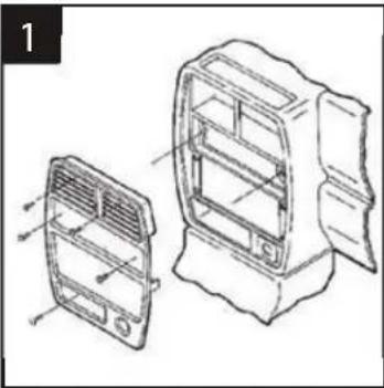
CHEVROLET Tracker 1998-04 • GEO Tracker 1992-97
SUZUKI Sidekick 1992-98 / Vitara series 1999-04
natural_image
Technical line drawing of a car air vent assembly with two views (front and side), no text or symbols presentDisconnect the negative battery terminal to prevent an accidental short circuit. Remove the cigarette lighter and climate control knobs. Remove the ashtray and (1) screw exposed. Pull out on the climate control cluster and remove (2) screws exposed. Unclip the radio trim bezel. Remove (4) screws from the factory head unit, slide the unit out and disconnect the wiring.
2
natural_image
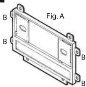
Technical line drawing of a rectangular electronic component labeled Fig. A, with no visible text or symbols beyond the label.
text_image
Fig. BCut and remove all mounting tabs on the Radio Housing EXCEPT tabs "B". (The mounting tabs can be identified by the stamped letter on the back of each tab). (see Fig. A). Cut and remove the (2) side clips on the back side of the radio trim bezel. (This will provide proper clearance when re-attaching the bezel after the aftermarket head unit has been installed). (see Fig. B). Skip to the Installation Instructions for ALL VEHICLES on Page #3.
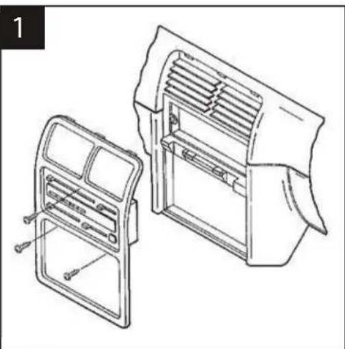
GEO Metro / SUZUKI Swift 1992-94
natural_image
Technical line drawing of a car air vent assembly with two views (front and side), no text or symbols presentDisconnect the negative battery terminal to prevent an accidental short circuit. Remove the climate control knobs. Remove (1) Phillips screw above and (2) Phillips screws below the climate controls. Unclip the radio trim bezel. Remove (4) screws from the factory head unit, slide the unit out and disconnect the wiring.
2

natural_image
Technical line drawing of a rectangular mechanical component with mounting holes and internal cavity (no text or symbols)Cut and remove all mounting tabs on the Radio Housing EXCEPT tabs "A". The mounting tabs can be identified by the stamped letter on the back of each tab. Skip to the Installation Instructions for ALL VEHICLES on Page #3.
SUZUKI Aerio 2003
1
natural_image
Line drawing of a computer monitor with a strap, no text or symbols presentDisconnect the negative battery terminal to prevent an accidental short circuit. Unclip the dash trim bezel and remove. Remove (4) Phillips screws securing the factory head unit and disconnect the wiring.
2
natural_image
Technical line drawing of a rectangular metal enclosure with mounting flanges (no text or symbols)Cut and remove all mounting tabs on the Radio Housing EXCEPT tabs "B". The mounting tabs cab be identified by the stamped letter on the back of each tab. Skip to the Installation Instructions for ALL VEHICLES on Page #3.
SUZUKI Esteem 1995-03
1

natural_image
Technical line drawing of two views of a device casing, showing internal components and a screw inserted (no text or symbols)Disconnect the negative battery terminal to prevent an accidental short circuit. Remove the climate control knobs. Remove (1) Phillips screw located above the radio opening. Unclip the radio trim bezel. Remove (4) screws from the factory head unit, slide the unit out and disconnect the wiring.
B

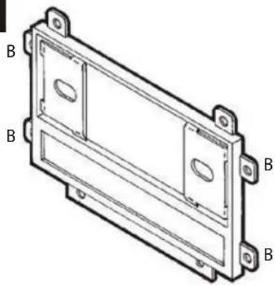
natural_image
Technical line drawing of a rectangular mechanical housing or enclosure with mounting holes and two labeled points B (no text or symbols present)Cut and remove all mounting tabs on the Radio Housing EXCEPT tabs "B". The mounting tabs cab be identified by the stamped letter on the back of each tab. Skip to the Installation Instructions for ALL VEHICLES on Page #3.
ALL VEHICLES
text_image
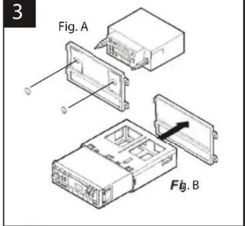
3 Fig. A Fig. B2-SHAFT HEAD UNITS: Slide the aftermarket head unit into the kit and secure with shaft nuts. (see Fig. A)
DIN HEAD UNITS: Cut and remove the shaft supports. Slide the DIN cage into the Radio Housing and secure by bending the metal locking tabs down. Slide the aftermarket head unit into the cage until secure. (see Fig. B)
text_image
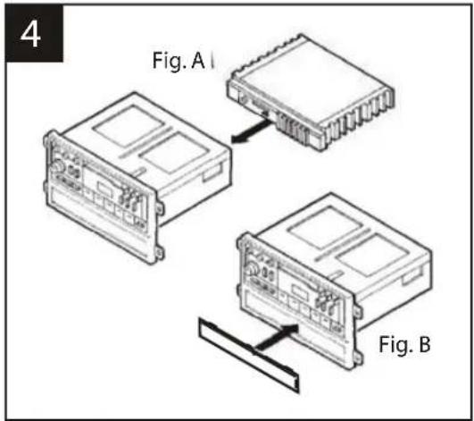
4 Fig. A I Fig. BIF AN EQUALIZER WILL BE INCLUDED : Slide the aftermarket equalizer into the back of the Radio Housing. Using the hardware included with the equalizer, mount the unit to the kit. (see Fig. A)
IF AN EQUALIZER WILL NOT BE INCLUDED: Snap the Equalizer Dummy Plate into the Radio Housing. (see Fig.B)
5
text_image
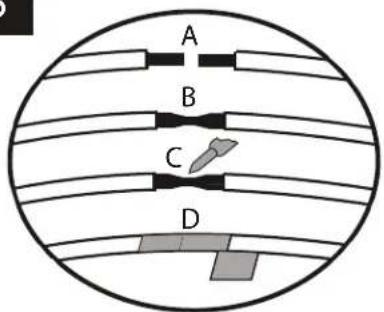
A B C DA) Strip wire ends back 12 "
B) Twist ends together
C) Solder
D) Tape
Locate the factory wiring harness in the dash. Metra recommends using the proper mating adaptor and making connections as shown. (Isolate and individually tape off the ends of any unused wires to prevent electrical short circuit).
natural_image
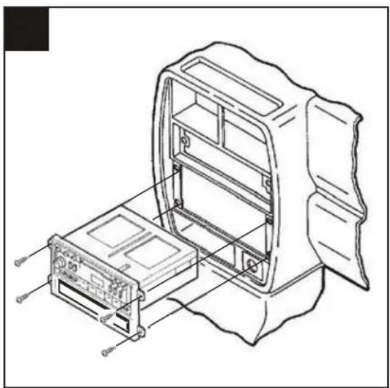
Technical line drawing of a device housing with internal components and mounting base (no text or symbols)Re-connect the battery terminal and test the unit for proper operation. Slide (4) Speed Clips over the holes in the sub-dash mounting brackets and mount the head unit/kit assembly with (4) Phillips Pan-Head Screws supplied.