95-9327B - Car accessory Metra - Free user manual and instructions
Find the device manual for free 95-9327B Metra in PDF.

User questions about 95-9327B Metra
0 question about this device. Answer the ones you know or ask your own.
Ask a new question about this device
Download the instructions for your Car accessory in PDF format for free! Find your manual 95-9327B - Metra and take your electronic device back in hand. On this page are published all the documents necessary for the use of your device. 95-9327B by Metra.
USER MANUAL 95-9327B Metra
natural_image
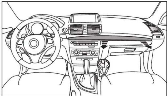
Interior view of a car showing the dashboard and display screen (no visible text or symbols)BMW 1 Series (without NAV, with automatic climate control) 2008-2013
Visit MetraOnline.com for more detailed information about the product and up-to-date vehicle specific applications
KIT FEATURES
- ISO DDIN radio provision
- Painted scratch resistant matte black to match the factory finish
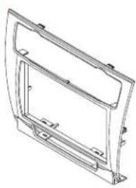
KIT COMPONENTS
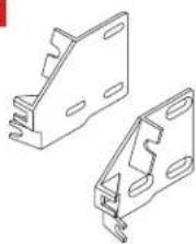
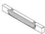
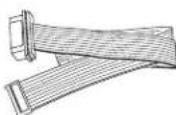
- A) Radio housing • B) Radio brackets • C) Switch panel cover • D) Ribbon cable • E) Panel clips • D) Phillips screws (8)
A
natural_image
Technical line drawing of a curved metal frame or panel assembly (no text or symbols)B
natural_image
Technical line drawing of two metal bracket components (no text or symbols)C
D
E

F

TABLE OF CONTENTS
Dash Disassembly 2-3
Kit Preparation 4
Kit Assembly 5
WIRING & ANTENNA CONNECTIONS (sold separately)
Wiring Harness: Please visit metraonline.com for wiring harness options
Antenna Adapter: 40-EU10
TOOLS REQUIRED
- Panel removal tool
- Phillips screwdriver
- Cutting tool
Attention! With the key out of the ignition, disconnect the negative battery terminal before installing this product. Ensure that all installation connections are secure before cycling the ignition to test this product.
DASH DISASSEMBLY
- Unclip and remove the dash trim panel above the radio and glove box. (Figure A)
- Unclip the climate control panel then unplug and remove. (Figure B)
Continued on the next page
natural_image
Interior view of a car dashboard and steering wheel (no text or symbols visible)(Figure A)

natural_image
Interior view of a car infotainment system showing dashboard, air vent, and control panel (no text or labels)(Figure B)
DASH DISASSEMBLY (CONT.)
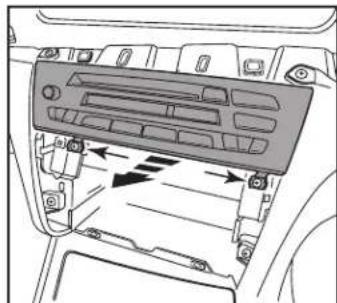
- Remove (2) screws securing the bottom of the radio, then unplug and remove the radio. (Figure C)
- Unclip the climate controls from the climate control panel and save for reassembly. (Figure D)
- Unclip and remove the switch panel below the climate controls (if equipped) (Figure E).
Continue to Kit Preparation
natural_image
Interior view of a car showing the dashboard and air vent system with directional arrows (no text or symbols)(Figure C) (Figure D) (Figure E)

natural_image
Technical illustration of a vehicle chassis with an arrow indicating motion, shown in two views: top view and side view (no text or symbols)
natural_image
Technical line drawing of a mechanical assembly with no visible text or symbolsKIT PREPARATION
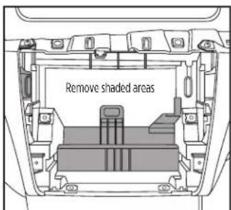
- Using a cutting tool, remove the sections of sub-dash indicated to provide clearance for the radio and climate controls. (Figure A)
- Install the (2) panel clips to the radio housing.
For models with a switch panel below the climate control.
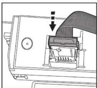
- Remove (5) screws securing the switch panel back plate, then remove the switch panel circuit board.
- Unplug the ribbon cable from the circuit board. (Figure B)
text_image
Remove shaded areas(Figure A)

natural_image
Diagram of an electronic device with a cable connector and indicator lights, no text or symbols present(Figure B)
- Attach the White connector from the ribbon cable supplied with the kit to the circuit board.
- Reinstall the circuit board back into the switch panel.
- Clip the climate control panel, and switch panel, into the radio housing. (Figure C)
- Attach the Black connector from the ribbon cable to the climate control panel. (Figure D)
For models without a switch panel below the climate control.
- Clip the switch panel cover to the radio trim panel.
- Disregard the ribbon cable, it will not be used in this application.
Continue to Kit Assembly

natural_image
Technical illustration of a car dashboard frame with ventilation slots and a handle (no text or symbols)(Figure C)
natural_image
Diagram of a device's internal structure showing a cable being inserted into a connector (no text or symbols visible)(Figure D)
KIT ASSEMBLY
ISO DDIN radio provision
- Attach the radio brackets to the radio using the screws supplied with the radio. (Figure A)
Note: Radio mounting screws must be flush with the mounting brackets. Countersunk flat-head screws have been provided if needed. (Figure A)
-
Locate the factory wiring harness and connector in the dash and complete all necessary connections to the radio. Metra recommends using the proper mating adapter from Metra and/or Axxess. Test the radio for proper operation.
-
Secure the completed assembly into the dash with the factory screws.
-
Reassemble the dash in reverse order of disassembly using radio trim panel assembly to complete the installation.

natural_image
Technical line drawing of an electronic device casing with mounting holes and screw fasteners (no text or symbols)(Figure A)
Having difficulties? We're here to help.

our Tech Support line at:
386-257-1187

mail at:
techsupport@metra-autosound.com
Tech Support Hours (Eastern Standard Time)
Monday - Friday: 9:00 AM - 7:00 PM
Saturday: 10:00 AM - 7:00 PM
Sunday: 10:00 AM - 4:00 PM

KNOWLEDGE IS POWER
Enhance your installation and fabrication skills b enselling in the most recognized and respected
mobile electronics school in our industry.
Log onto www.instellerinstitute.com or call
600-354-8782 for more information and take steps toward a better tomorrow.

Metra recommends MECP certified technicians