CG60WOK-F - Stove Porter & Charles - Free user manual and instructions
Find the device manual for free CG60WOK-F Porter & Charles in PDF.

User questions about CG60WOK-F Porter & Charles
0 question about this device. Answer the ones you know or ask your own.
Ask a new question about this device
Download the instructions for your Stove in PDF format for free! Find your manual CG60WOK-F - Porter & Charles and take your electronic device back in hand. On this page are published all the documents necessary for the use of your device. CG60WOK-F by Porter & Charles.
USER MANUAL CG60WOK-F Porter & Charles
Operating and Installation Instructions
CURRENT STANDARD: ANSI Z21.1-2016/CSA 1.1-2016

text_image
SA® C US
text_image
DESIGN CERTIFIED®
text_image
SP CERTIFIED®Gas Cooktop
Model:
CG60WOK-F CG76WOK-F CG90WOK-F
To prevent accidents and machine damage, read the Operating Manual
before
installation or use.
en
WARNING:
If the information in these instruction is not followed exactly, a fire or explosion may result causing property damage, personal injury or death.
- Do not store or use gasoline or other flammable vapors and liquids in the vicinity of this or any other appliance.
-
WHAT TO DO IF YOU SMELL GAS
-
Do not try to light any appliance.
- Do not touch any electrical switch.
- Do not use any phone in your building.
- Immediately call your gas supplier from a neighbor's phone. Follow the gas supplier's instructions.
- If you cannot reach your gas supplier, call the fire department.
- Installation and service must be performed by a qualified installer, service agency or the gas supplier.
Leak testing of the appliance shall be conducted according to the manufacturer's instructions
This cooktop is NOT designed for installation in manufactured (mobile) homes or in recreational vehicles.
Proper installation is your responsibility. Make sure your appliance is properly installed and grounded by a qualified installer
The installation must conform with local codes or, with the National Fuel Gas Code, ANSI Z223.1/NFPA 54 or, in Canada, the Natural Gas and Propane Installation Code, CSA B149.1.
If an external electrical source is utilized, the appliance, when installed, must be electrically grounded in accordance with local codes or, in the absence of local codes, with the National Electrical Code, NFPA 70 or the Canadian Electric Code, CSA C22.1-02.
- Note to the installer:
Please leave this instruction book with the consumer for the local electrical / gas inspector's use.

WARNING:
- This appliance is intended for use in the home only.
- Use this appliance only for its intended purpose. The manufacturer cannot be held liable for damage caused by improper use of this range.
- This appliance complies with current safety regulations.
Improper use of this cooktop can result in personal injury and material damage. - Read all the instructions before installing or using the range for the first time.
- Keep these operating instructions in a safe place and pass them on to any future user.
NOTE: This cooktop is manufactured for use with natural gas. To convert the appliance to LP/Propane gas, see the instructions in the Gas Conversion instructions.
The proper gas supply connections must be available. See “Gas supply requirements”.

IMPORTANT:
Please ensure that the cut out measurement, venting, and wiring is as specified in the range measurement section of this manual.
A licensed electrician with relevant qualifications must perform electrical work when installing or servicing the appliance. The supply cable and fuse rating must be suitable for the appliance. You must never repair or replace any part of the appliance unless specifically recommended in the operation manual.
Gas supply requirements
MAXIMUM GAS-SUPPLY PRESSURE, ALL MODELS 12 psi
VENTILATION
The room containing this range should have an air supply in accordance with local regulations. Ventilation opening must not be covered or obstructed in any way
- All rooms require an open window, or equivalent, and some rooms will also require a permanent vent.
- For room areas up to 5m^2 an air vent of 100cm^2 is required.
- For room areas between 5m^2 and 100cm^2 an air vent of 50cm^2 is required.
- If the room is greater than 5m^2 and has a door that opens directly to the outside, then no air vent is required.
- If there are other fuel-burning appliances in the same room, check your local regulations to determine the air vent requirements.
WARNING: The appliance must be isolated from the gas supply piping system by closing its individual manual shut-off valve during any pressure testing of the gas supply piping system at test pressures equal to or less than 1/2 psi (3.5 kPa). the maximum gas supply pressure in accordance with the inlet pressure rating of the gas appliance pressure regulator supplied.

WARNING:
This appliance is not intended for use by persons (including children) with reduced physical, sensory, or mental capabilities, or lack of experience and knowledge, unless they have been given supervision or instruction concerning use of the appliance by a person responsible for their safety.
Children should be supervised to ensure that they do not play with the appliance. During use the appliance becomes hot. Care should be taken to avoid touching heating elements inside the oven.
IMPORTANT SAFETY INSTRUCTIONS
Installation and connection
When using your gas appliance follow basic safety precautions including the following:
Read all instructions before using for the first time.
▶ Be certain your appliance is properly installed and grounded by a qualified technician.
To guarantee the electrical safety of this appliance, continuity must exist between the appliance and an effective grounding system. It is imperative that this basic safety requirement be met. If there is any doubt, have the electrical system of the house checked by a qualified electrician.
▶ Install the appliance so that the power cord and gas piping do not come into contact with any portion of the cooktop which may become hot during use.
Do not connect the appliance to the main electrical supply using an extension cord. Extension cords do not meet the safety requirements of this appliance.
Before servicing, turn off the gas valve and disconnect the power supply by either removing the fuse, unplugging the unit or manually “tripping” the circuit breaker.
This equipment has not been designed for maritime use or for use in mobile installations such as aircraft or recreational vehicles. However, under certain circumstances it may be possible for installation in these applications. Please contact the Technical Service Department with specific requirements.
▶ After connecting the appliance test for leaks according to the installation instructions.
If there is any doubt concerning installation contact Technical Service Department.
IMPORTANT SAFETY INSTRUCTIONS
Correct usage
Do not operate the cooktop until it is properly installed in the countertop.
This appliance is intended for residential cooking only.
▶ Use the appliance only for its intended purpose.
Be sure drafts do not blow flammable material toward the flames or push the flames so that they extend beyond the edges of the pan.
▶ Install the cooktop in a room that has sufficient ventilation.
This appliance must not be operated outdoors.
Do not use aluminum foil to line any part of the cooktop.
For proper lighting and performance of the burners, keep the igniters clean and dry.
▶ Make sure all components of the gas burners are assembled correctly before using the cooktop.
▶ Ensure that any burners in use are always covered with a pan.
Do not use pans that extend past the burner grate. Using larger pans may cause the flames to spread out and damage the surrounding countertop or other countertop appliances.
For safety and stability, do not use pans with a bottom diameter smaller than the burner grate.
▶ Only certain types of glass, ceramic or other glazed cookware are suitable for use on a cooktop without breaking due to the sudden temperature change.
Do not store aerosols, gasoline, combustibles or any other flammable materials underneath or adjacent to the cooktop.
WARNING - NEVER use this appliance as a space heater to heat or warm the room. Doing so may result in carbon monoxide poisoning and overheating.
Protection from damage
Do not use a steam cleaner to clean the appliance. Steam could penetrate electrical components and cause a short circuit.
▶ Spills containing salt or sugar should be removed immediately.
Personal safety
The burners become very hot when in use. Make sure that no one comes in contact with them.
Do not leave children unattended in an area where the appliance is in use.
Do not store toys or items of interest to children in cabinets above or behind the cooktop. Children climbing onto the cooktop to reach these items may become seriously injured.
Do not allow children to operate or play with the cooktop. Keep all pans out of the reach of children.
▶ Use only dry, heat resistant potholders. Moist or damp potholders used on hot surfaces can result in steam burns. Do not let the potholder touch the hot burners. Do not use towels or other bulky items near the appliance.
▶ Be aware of loose fitting or hanging garments when operating the cooktop, they may present a fire hazard.
Do not heat unopened food containers. Built-up pressure may cause the container to burst and result in injury.
Do not store items on the cooktop when not in use.
Do not let cooking grease or other flammable materials accumulate on the appliance.
Do not leave the cooktop unattended while in use. Boil-overs cause smoking, and greasy spill-overs may ignite.
Do not use water on grease fires. Smother any fire or flame, or use a dry chemical or foam-type extinguisher.
Do not flambé under an exhaust hood. Flames could be drawn up into the hood by the suction or the grease filters may ignite.
For safety reasons the flame should be adjusted to be the same size as the bottom of the pan or smaller. Do not use small pans with high flame settings as the flames can climb the sides of the pan.
▶ Only use cooking utensils suitable for cooktop use.
▶ Always position pan handles and utensils inward so they do not extend over adjacent work areas, burners or the edge of the cooktop.
If there is a drawer directly underneath the appliance without a wooden base in between, ensure that no aerosols, combustible liquids or other easily flammable materials are kept in it. If cutlery inserts are to be placed in the drawer, these must be made of a heat-resistant material.
IMPORTANT SAFETY INSTRUCTIONS
Damage to the appliance
In the event of damage or a defect, turn off the appliance immediately. Turn off the gas shut off valve and disconnect completely from the electricity supply. Contact the Technical Service Department. Do not use the appliance until it has been repaired.
Ensure power is not supplied to the appliance while repair work is carried out.
▶ Repairs should only be performed by qualified technicians to ensure safety. Repairs and other work by unqualified persons could be dangerous. Under no circumstance open the outer casing of the appliance.
While the appliance is under warranty repairs should only be performed by a Miele authorized service technician. Otherwise the warranty is void.
Further safety notes
When using a portable appliance near the cooktop, make sure that its power cord does not come in contact with the cooktop.
Do not use containers made of plastic or aluminum. They may melt at high temperatures.
Do not heat empty pots or pans, they may be damaged.
Before discarding an old appliance, disconnect it from the gas and electrical supply and cut off the power cord to prevent it from becoming a hazard.
SAVE THESE
INSTRUCTIONS
Cleaning the cooktop
Before using for the first time clean the appliance as follows:
■ Wash the gas burner assembly with a mild solution of warm water and liquid dish soap.
■ Wipe dry and reassemble the parts in the proper order (see “Cleaning and care”).
■ Wipe the cooktop with a damp cloth and dry thoroughly.
Metal components have a protective coating which may give off a slight odor the first time your new appliance is heated.
The harmless odor will dissipate after a short time and does not indicate a faulty connection or appliance defect.
Ignition-System
The gas cooktops are equipped with a Fast-Ignition-System which incorporates the following features:
- The control knob can be released once it is turned to the largest flame symbol.
Turning on and off / Regulating
The control knob is used to light the burner and to regulate the strength of the flame.
Normal / Fast burner
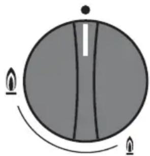
natural_image
Simple circular diagram with a central vertical line and two flame-like symbols at the bottom (no text or labels)●Cooktop is turned off
Highest flame
Lowest flame
Turning on
■ To light a burner press down and turn the corresponding control knob counterclockwise to the largest flame symbol. Release the knob. The ignitor will click and ignite the gas.
The ignition process lasts about 2 - 5 seconds. The flame should light within 4 seconds.
■ Adjust the knob to the desired setting.
Turning off
■ Turn the control knob clockwise to “●”.
This stops the flow of gas and turns off the cooktop.
The knob must only be turned left to turn the appliance on and right to turn it off.
If the knob is turned,
- on without pressing it down first,
- clockwise past the 12 o'clock position, or
- counterclockwise past the smallest flame symbol,
parts of the cooktop could be damaged.
Pan size
- Set the cooktop to a high flame when using a large diameter pan and low flame when using small diameter pans.
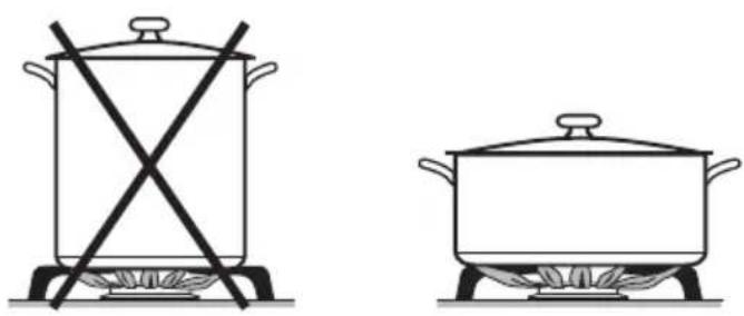
natural_image
Two cooking pots on stovetop with crossed x-bracing, no text or symbols present- Generally, wide / shallow pans will heat quicker and cook more evenly than narrow / tall ones.
- Using oversized pans may cause the flames to spread out and damage the surrounding countertop or other countertop appliances. The proper pan size will also improve efficiency.
- Do not use small pans with high flame settings, the flames may climb the sides of the pan.
- Pots with a smaller diameter than the pan support and pots that do not sit securely (without wobbling) are hazardous and should not be used.
Suitable pans
Unlike pans used on an electric cooktop, the bases do not need to be even for good results.
Thick pan bases will give more even results, as hot spots are reduced due to better heat distribution.
Thin pan bases will conduct the heat faster but not as evenly as thick pan bases. Stir the food frequently to prevent burning.
Wok burners
You can use a wok on these burners without any additional rings, trivets, etc.
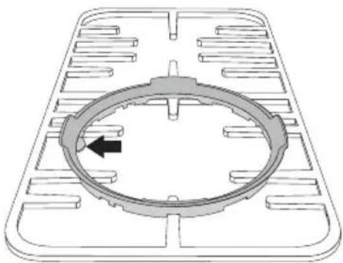
natural_image
Technical diagram of a mechanical component with a circular ring and internal slots, no text or symbols present.If you wish to use the wok ring, for extra stability, attach it as shown (depending on your grates).
Mini Trivet

natural_image
Pure mechanical cross-shaped diagram without any text, numbers, or symbolsThe mini-trivet included with this cooktop is to be used for cooking vessels of diameter 120 mm or smaller
Examples of positioning of mini-trivet
natural_image
Pure electrical circuit lines without any symbolsMODEL:CG60WOK-F
natural_image
Pure architectural floor plan lines without any text, numbers, or symbolsMODEL:CG76WOK-F
natural_image
Pure electrical circuit lines without any symbolsMODEL:CG90WOK-F
Never use a steam cleaner to clean this cooktop. Pressurized steam could cause permanent damage to the surface and to components.
Do not use any sharp or pointed objects which could damage the seal between the frame and the countertop.
Never use scouring agents, pads, abrasive cleaning agents, or strong cleaners, e.g. oven sprays, stain or rust removers, these could damage the surface of the appliance.
Keep the ignitor in the burner dry. If it gets wet it will not spark.
Dry your cooktop thoroughly after cleaning it to prevent lime deposits.
Spills containing salt or sugar should be cleaned immediately.
Cooktop
Let the appliance cool to a safe temperature before removing the grates.
■ Clean the grates, cooktop and knobs with a sponge and a mild solution of warm water and liquid dish soap.
■ Soak baked or hardened spills. Dry the cooktop and grates thoroughly after cleaning.
The stainless steel surfaces can be cleaned using a non-abrasive stainless steel cleaner.
To help prevent resoiling, a conditioner for stainless steel can also be used. Apply sparingly with even pressure.
Printed surfaces
Remove any soiling which comes into contact with the printed flame symbols and the Miele logo right away. Soiling, particularly salty food or liquid and olive oil, can cause damage if left on the printed surfaces for too long. Do not use stainless steel cleaning agents on the printed surfaces. This can rub off the print.
Stainless steel colored knobs
These controls may become discolored or damaged if not cleaned regularly.
Do not use a stainless steel cleaner on the knobs.
Burners
The burners can be dismantled and cleaned when cool.
■ Remove the burner parts and wash them in a solution of hot water and liquid dish soap. Dry them thoroughly. Make sure that the flame holes are clean and completely dry.
■ Wipe the burner base clean with a damp cloth and then dry.
■ Gently wipe the ignitor and ignition safety control with a slightly damp cloth, and then wipe dry.
Make sure that no liquid gets into the appliance.
Reassembling the normal and fast burners
text_image
Technical diagram of a mechanical device with numbered parts labeled 1 to 41 Burner
2 Flame safeguard sensor (where fitted)
3 Injector
4 Ignition spark plug
⚠️Repairs should only be carried out by an authorized technician in accordance with local and national safety regulations. Unauthorized repairs could cause injury or appliance damage.
The burners do not ignite after several attempts.
| Possible fault Fix | |
| – The burners are assembled incorrectly.– The gas valve is closed.– The burners are wet and soiled and/or the flame holes in the burners are soiled and clogged.– The igniters are wet.– The cooktop is not plugged in and the circuit breaker has tripped. | – Reassemble the burners as shown in “Cleaning and Care - Burners”.– Open the gas valve.– Clean the burners. See “Cleaning and Care”.– Dry the igniters.– Plug the cooktop in and restore power. If lack of power is the problem, the cooktop can be lit with a match. See “Using the cooktop during a power failure”. |
| The flame goes out after being lit. | |
| – The burners are assembled incorrectly.– The flame holes in the burners are soiled and clogged. | – Reassemble the burners as shown in “Cleaning and Care - Burners”.– Clean the burners. See “Cleaning and Care”. |
| The igniters no longer work. | |
| – Residue has been built up between the ignitor and the burner.– Make sure the ignitor is dry. | – Clean the burners. See “Cleaning and Care”.– Dry the igniters. |
| The flame appears different than usual. | |
| – The burners are assembled incorrectly. | – Reassemble the burners as shown in “Cleaning and Care - Burners”. |
In the event of a fault which you cannot easily fix yourself, please contact the Technical Service Department at the address on the back of this booklet.
When contacting Technical Service please quote the serial number and model of the cooktop. This information is visible on the silver data plate supplied with the cooktop.
Adhere the data plate sticker to the box below:
natural_image
Diagram showing a screw and a mechanical component with directional arrows (no text or symbols)Installation Instructions
To prevent accidents and machine damage read these instructions
before
installation or use.
IMPORTANT SAFETY INSTRUCTIONS
Installation
The minimum distances given in these Installation instructions are to combustible surfaces, and must be observed to ensure safe operation. Failure to do so increases the risk of fire.
The cabinetry and venting hood should be installed first to prevent damage to the cooktop.
Gas appliances should only be installed in a well ventilated area.
The countertop must be bonded with heat resistant (212 °F/100 °C) adhesive to prevent distortion or dissolving.
The cooktop should only be installed as shown in the illustrations while maintaining the required safety distances shown. Do not install the cooktop between two tall cabinets, this is a fire hazard.
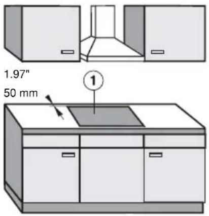
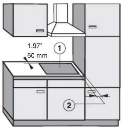
① = indicates cooktop cut-out
② = minimum distance between cut-out and a tall cabinet:
4.72" (12 cm)
This appliance has not been designed for maritime use or for use in mobile installations such as recreational vehicles or aircraft. However, under certain conditions it may be possible for installation in these applications. Please contact the Technical Service Department with specific requirements.
text_image
1.97" 50 mm ①recommended
text_image
1.97" 50 mm ① ②not recommended

natural_image
Architectural diagram of a multi-level kitchen structure with diagonal braces and no visible text or symbolsnot allowed
The cooktop must not be installed over a dishwasher, washer, dryer, refrigerator or freezer. Heat radiated by the cooktop may damage the appliances.
▶ Deep fat fryers must not be installed next to gas cooktops. Gas flames can ignite splattering oil. A distance of at least 12" (305 mm) should be maintained between these two appliances. The minimum distance between two cooktops must be 4" (100 mm).
▶ Install the appliance so that the power cord or gas piping does not come into contact with any portion of the cooktop which may become hot during use.
If the cabinet manufacturer recommends a greater distance, follow that manufacturers recommendation.
This appliance must be installed with its own shut off valve and the included gas pressure regulator. Both the valve and the regulator must be easily accessible to the consumer after the appliance is installed.
This appliance must be disconnected from the gas supply during any pressure testing of the system performed in excess of ^1/2 psi (3.5 kPa). This appliance must be isolated at test pressures equal to or less than ^1/2 psi (3.5 kPa).
Any pipe connections must be made using a thread sealant approved for gas connections. Failure to correctly install these items could lead to a gas leak and subsequent explosion.
When installing the cooktop under a venting hood, always observe the minimum distance recommended by the hood manufacturer.
Keep this instruction book in a safe place for reference and pass it on to any future user.
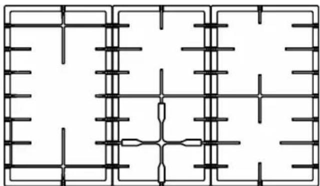
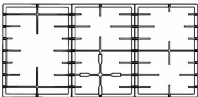
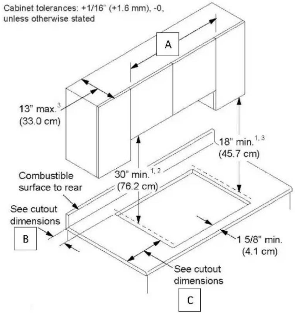
MINIMUM REQUIRED CLEARANCES AROUND THE COOKTOP
text_image
Cabinet tolerances: +1/16" (+1.6 mm), -0, unless otherwise stated 13" max.³ (33.0 cm) 18" min.¹,³ (45.7 cm) Combustible surface to rear 30" min.¹,² (76.2 cm) See cutout dimensions B 1 5/8" min. (4.1 cm) See cutout dimensions C1 Distance to the combustible surfaces measured from cooking surface (top of cooktop grate)
2 If installing with an overhead range hood, check the hood specification for minimum required clearances.
3 This specification does not apply for cabients located greater than a horizontal distance of 5 1/2" (14.0 cm) from edge of cooktop. Allow 6 7/8" (17.5 cm) from cutout edge.
| MODEL | “A” Minimum | “B” Minimum | “C” Minimum |
| CG60WOK-F | 24” (60,9 cm) | 1,97” (5 cm) | 4,72” (12 cm) |
| CG76WOK-F | 30” (76,2 cm) | 1,97” (5 cm) | 4,72” (12 cm) |
| CG90WOK-F | 36” (91,4 cm) | 1,97” (5 cm) | 4,72” (12 cm) |
text_image
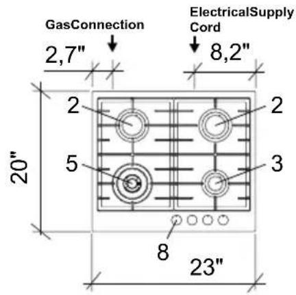
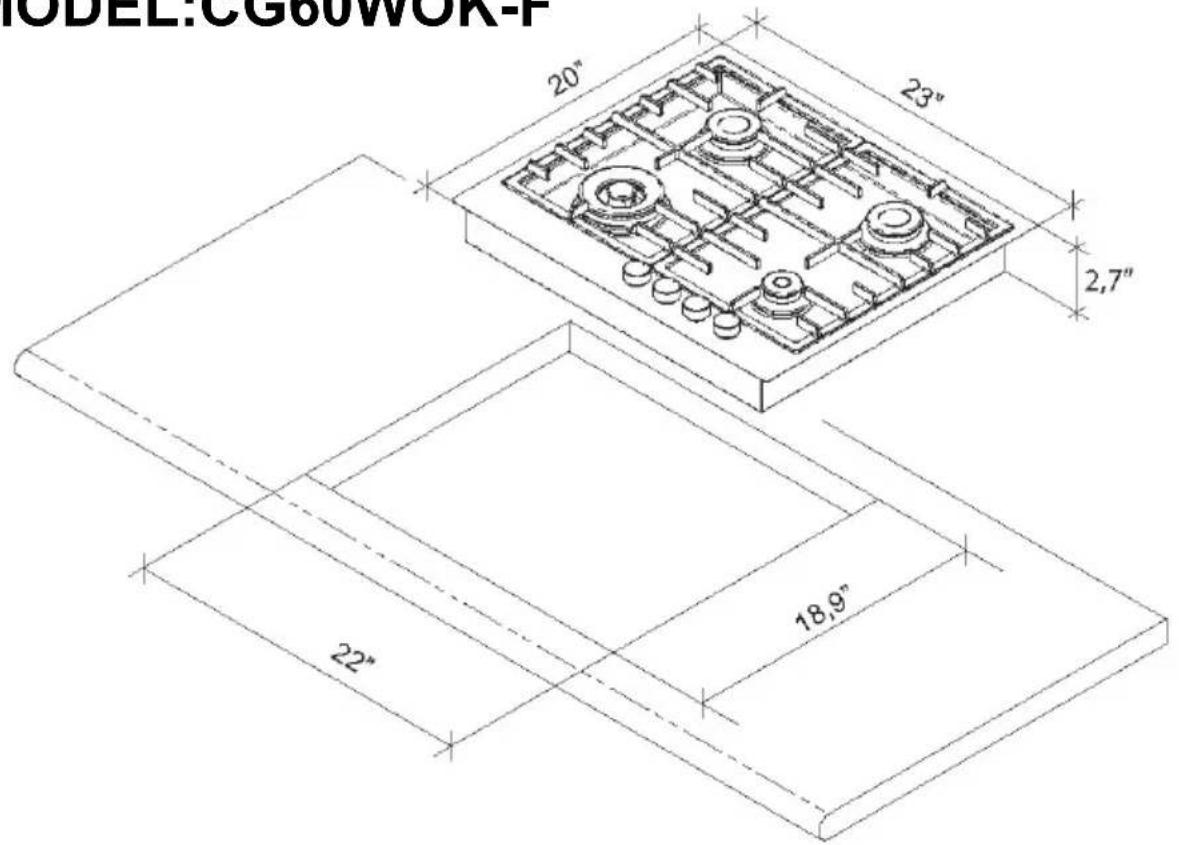
GasConnection 2,7" ElectricalSupply Cord 8,2" 20" 2 2 5 3 8 23"MODEL:CG60WOK-F
Depth of cooktop casing from benchtop surface : 2,7"
text_image
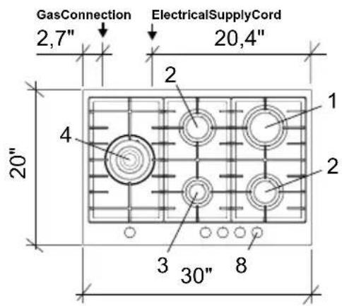
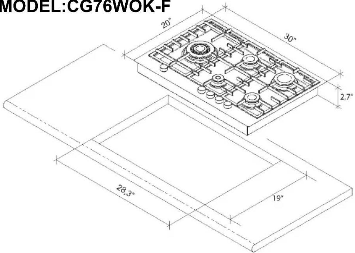
GasConnection 2,7" ElectricalSupplyCord 20,4" 20" 1 2 4 3 8 30"MODEL:CG76WOK-F
Depth of cooktop casing from benchtop surface : 2,7"

text_image
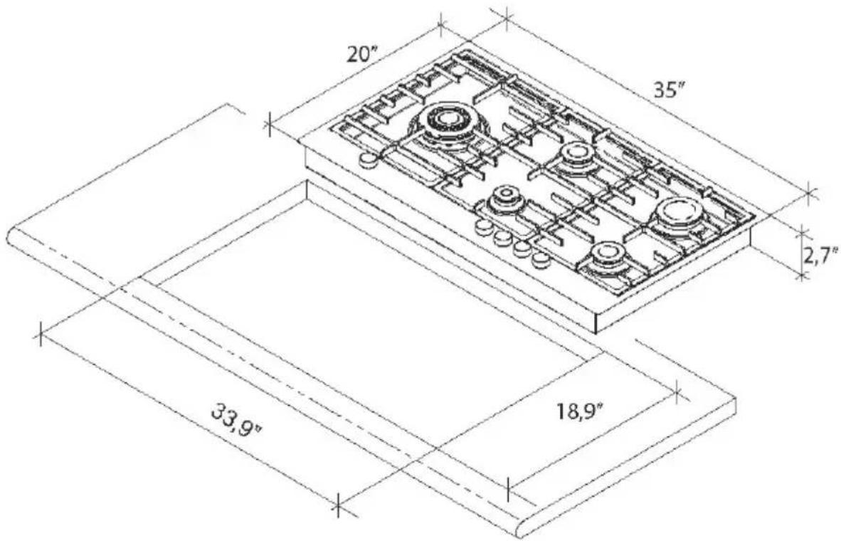
Gas Connection 2,7" Electrical Supply Cord 24" 20" 4 1 2 3 8 35"MODEL:CG90WOK-F
Depth of cooktop casing from benchtop surface : 2,7"
| NG | Universal | LPG | |
| 1 Rapid burner | 11500 | BTU/hr 12000 BTU/hr | |
| 2 Semi-rapid burner | 7600 | BTU/hr 8250 BTU/hr | |
| 3 Auxiliary burner | 4900 | BTU/hr 5700 BTU/hr | |
| 4 Triple ring burner | 16500 | BTU/hr 16500 BTU/hr | |
| 5 Double ring burner | 11000 | BTU/hr 12500 BTU/hr | |
| 8 Control knob for burner |
MODEL:CG60WOK-F
text_image
MODEL:CG60WOR-F 20" 23" 2,7" 22" 18,9"MODEL:CG76WOK-F
text_image
MODEL:CG76WOK-F 20" 30" 2,7" 28,3" 19"MODEL:CG90WOK-F
text_image
20" 35" 2,7" 33,9" 18,9"Installation
■ Prepare the work top cut-out as shown in the diagram.
■ Seal the cut surfaces with a suitable heat-resistant sealant to avoid swelling caused by moisture.
If during installation, the corners of the frame are not flush with the work top surface, the corner radius (max. ^3/_16 " [4 mm]) can be carefully filed to fit.
Setting the cooktop into place
text_image
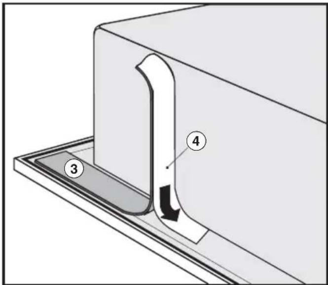
Technical diagram showing a mechanical component with labeled parts 3 and 4, likely illustrating a cutting or assembly process.■ After removing the protective backing, stick the supplied seal, under the edge of the cooktop.
■ Screw the gas regulator onto the nipple underneath the cooktop. (See "Gas Connection - Gas pressure regulator".)
■ Feed the power cord through the cut-out to the power outlet.
■ Set the cooktop in the cut-out and center it.
Install the appliance so that the power cord and gas piping does not come in contact with any portion of the cooktop which may become hot during use.
Securing the cooktop
- Secure the cooktop with the included fixing bracket.

text_image
C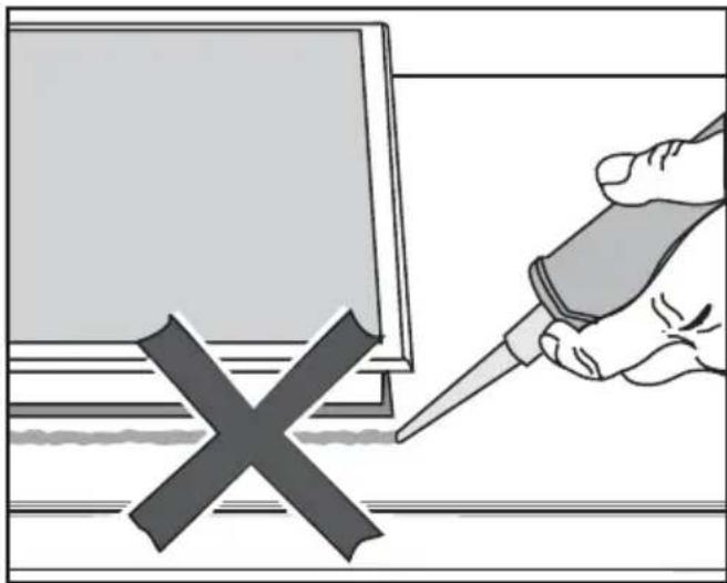
natural_image
Illustration of a hand using a screwdriver to mark a cross symbol on a computer screen (no text or symbols present)The sealing strip under the edge of the top part of the cooktop provides a sufficient seal for the worktop.
Do not let sealant get in between the cooktop frame and the worktop. This could cause difficulties if the cooktop ever needs to be taken out for servicing and possibly result in damage to the cooktop frame or the worktop.
This appliance must be grounded according to local or national codes.
All electrical work should be performed by a qualified electrician in accordance with local codes and with the:
- National Electrical Code ANSI / NFPA No. 70 for the USA
or
- Canadian Electrical Code Part I for Canada (CSA Standard C 22.1).
WARNING
Disconnect the appliance from the main power supply before installation or service. To reduce the risk of electric shock, make sure that the appliance is properly grounded after installation.
Power supply
The automatic ignition requires that the cooktop be connected to a 120 VAC, 60 Hz power supply. The supply line should be protected by a 15 A fuse.
Actual power consumption (during ignition only) is 25 W.
This appliance is equipped with a 3.3 ft. (1.0 m) long power cord that is ready for connection to the appropriate outlet.
Place the power outlet so that it is accessible after the appliance has been installed in the countertop.
This appliance is equipped with a three-prong grounding plug to prevent shock hazards. It should be plugged directly into a properly grounded outlet. Do not cut or remove the grounding prong from the plug. If the plug does not fit the outlet, have the proper outlet installed by a licensed electrician.
To guarantee the electrical safety of this appliance, continuity must exist between the appliance and an effective grounding system. It is imperative that this basic safety requirement be met. If there is any doubt, have the electrical system of the house checked by a qualified electrician.
Note to the installer
Please leave these instructions with the consumer or the appliance.
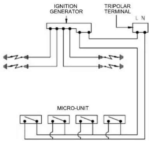
Wiring diagram
MODEL: CG60WOK-F
flowchart
graph TD
    A["IGNITION GENERATOR"] --> B["MICRO-UNIT"]
    C["TRIPOLAR TERMINAL"] --> B
    B --> D["Power Supply"]
    style A fill:#f9f,stroke:#333
    style C fill:#f9f,stroke:#333
    style B fill:#ccf,stroke:#333
    style D fill:#cfc,stroke:#333
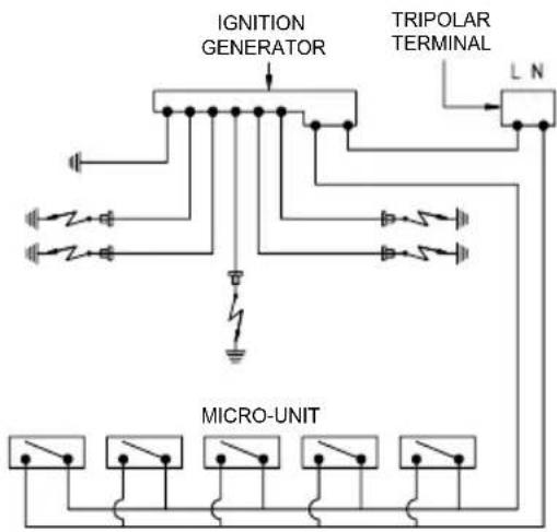
MODEL: CG76WOK-F / CG90WOK-F
text_image
IGNITION GENERATOR TRIPOLAR TERMINAL L N MICRO-UNIT⚠ Caution: Label all wires prior to disconnection when servicing controls. Wiring errors can cause improper and dangerous operation. Verify proper operation after servicing.
Installation and service must be performed by a qualified installer, service agency or gas supplier.
In Massachusetts a licensed plumber / gas fitter is required.
This appliance must be installed with its own shut off valve and the included gas pressure regulator. Both the valve and the regulator must be easily accessible to the consumer to turn on or shut off the gas supply after the appliance is installed.
This appliance and its individual shut off valve must be disconnected from the gas supply during any pressure testing of that system performed in excess of 12 psi (3.5 kPa). The appliance must be isolated from the gas supply line by closing its individual manual shut off valve at test pressures equal to or less than 12 psi (3.5 kPa).
Any pipe connections must be made using a thread sealant approved for gas connections. Failure to correctly install these items could lead to a gas leak and subsequent explosion.
The gas connection must be made in accordance with local codes or, in the absence of local codes, with
- the National Fuel Gas Code,
ANSI Z 21.1 / NFPA 54
for the USA
or - the current Can / CGA B 149.1 and .2 Installation Codes for gas burning appliances for Canada.
Make sure that the maximum gas supply pressure before the gas pressure regulator is never more than 12 psi for both natural gas or LP gas.
The minimum required gas pressure to get the required gas input is 4" w.c. for natural gas 10" w.c. for LP gas.
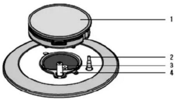
Gas pressure regulator
A pressure regulator that is convertible from natural to LP gas (Propane) or vice versa is included with the appliance. The included regulator corresponds with the gas type of the cooktop. Verify before installing.
The adjusted pressure is: natural gas - 5" w.c.
LP gas - 10" w.c.

text_image
Technical diagram of a mechanical assembly with labeled parts 1, 2, and 3, showing a bolted component and wiring connections.①Cooktop
② 1 / 2 " NPT
③Regulator
As shown in the above diagram, the included regulator must be used when connecting the cooktop to your gas supply. Make sure the regulator is easily accessible for adjustment after the appliance has been installed.
For convenience, an AGA or CGA approved flexible stainless steel gas hose (accordion type) may be used between the gas connection and the regulator. This will allow the appliance to be lifted out of the countertop for cleaning or servicing. Make sure that any drawers, cabinet doors, etc., do not rub on this gas hose.
Do not use any regulator unless it has been supplied by ..... Doing so may cause a gas leak.
If there is any doubt concerning installation contact the Technical Service Department:
After connecting the appliance check all fittings for gas leaks e.g. with soapy water.
When installed properly, the flame will be steady and quiet. It will also have a sharp, blue inner core that will vary in length proportional to the burner size. Flame adjustment will not be necessary.

text_image
ATTENTION MAXIMUM GAS-SUPPLY PRESSURE, ALL MODELS ½ psiNominal Rating Table
GAS TRANSFORMATIONS AND ADJUSTMENTS
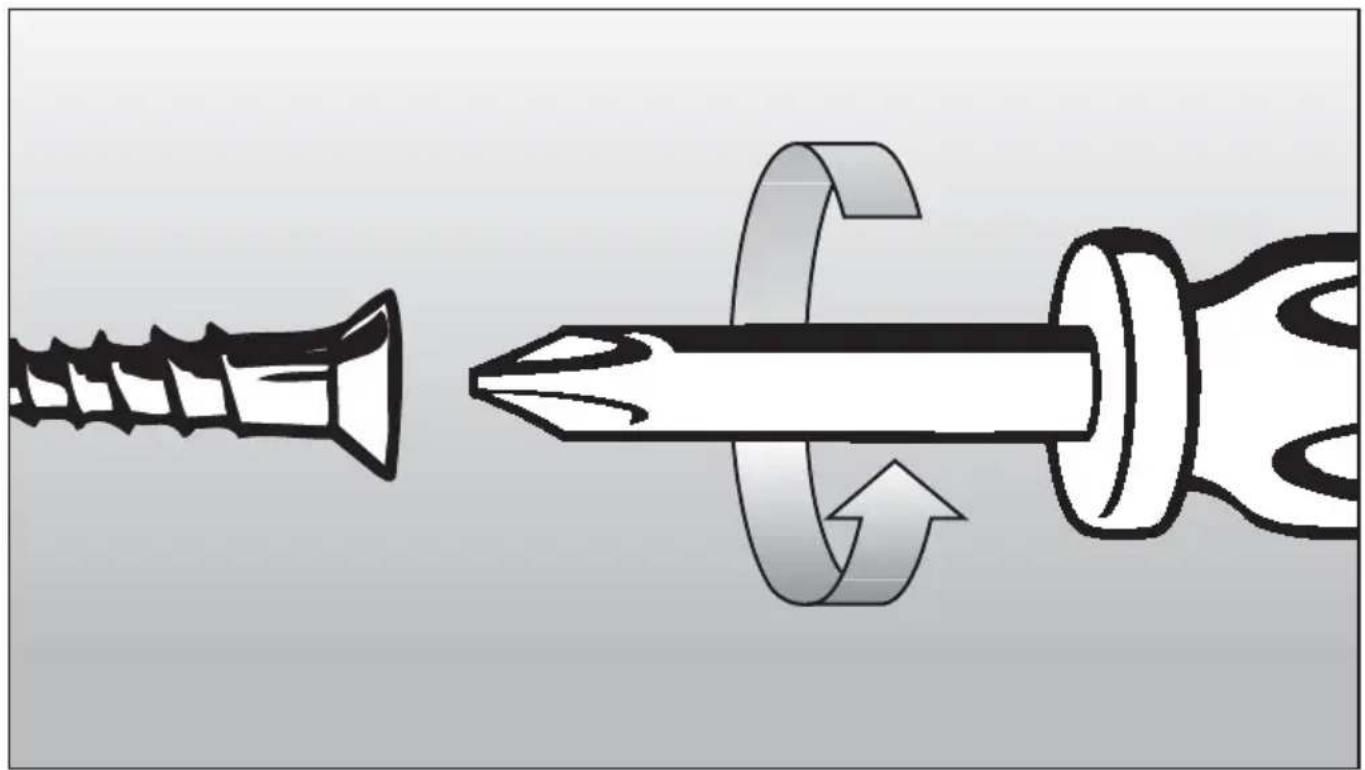
Replacing the nozzles
If the equipment is adjusted for a type of gas that is different from the original, it is necessary to replace the burner nozzles as well. The nozzles used to replace the original must be in accordance with the table of the technical characteristics enclosed.
To remove the racks and burners by means of a straight spanner 'L', unscrew the nozzle 'U' (Fig.7) and substitute it with the corresponding one and tighten the nozzle.
Adjusting the burners
The flame should always stay alight when the burner is switched on, even if there is an abrupt shift from the maximum to minimum flame position. If the flame does not stay alight, adjust it as follows:
- Start the burner
- Turn the tap up to the minimum position (small flame)
- Remove the knob from the tap rod
- Using a flat-tip screwdriver 'C' into the hole 'F' of the tap (fig.8) turn the by-pass screw up.
text_image
L U 7
text_image
F 8
CAUTION
Before proceeding with the conversion, shut off the gas supply to the appliance Prior to disconnecting the electrical power.
THIS APPLIANCE WAS CONVERTED ON
DAY......MONTH......YEAR......
TO GAS...... ( NAME AND ADDRESS OF ORGANIZATION MAKING THE CONVERSION) WITH KIT SUPPLIED BY THE FACTORY, WHICH ACCEPTS THE RESPONSABILITY THAT THIS CONVERSION HAS BEEN PROPERLY MADE
Disposal of packing materials
The cardboard box and packing materials are biodegradable and recyclable. Please recycle.
Disposal of an old appliance
Old appliances contain materials that can be recycled. Please contact your local recycling center about the possibility of recycling these materials.
Before discarding an old appliance, disconnect it from the gas and electrical supply and cut off the power cord to prevent it from becoming a hazard.
Q - Warranty
Porter&Charles products are designed and built to the highest standards.
We expect your appliances to provide many years of trouble free enjoyment.
In the event of an appliance requiring attention, each appliance is covered by a 2-year warranty from the date of purchase.
Refer to warranty policy for complete terms and conditions.
Coverage is for costs of parts and labour for appliances in capital cities & metropolitan areas. We reserve the right to charge directly for handling expenses outside the metropolitan region.
Porter&Charles products are supported by a national service support system. Call our customer service department for attention.
Please retain your invoice to quote should you require service assistance. This will identify your product for our priority service back-up. Please attach your invoice to this manual for easy future reference. To register your purchase, you can either complete the section below to mail or fax, or register online at www.porterandcharles.ca/warranty-information.
Porter&Charles
871 Cranberry Court
Oakville, ON L6L 6J7
Canada
Tel: 905-829-3980
Fax: 905-829-3985
Email: marketing@euro-line-appliances.com
For Service & Parts:
EURO-PARTS
1-800-678-8352
Important: Please record details of your purchase below and mail or fax to Porter&Charles ----cut along line ----
Name: ____ Tel No ____
Address:
City : ____ Prov/State: ____ Postal Code/ZIP: ____
Where purchased: ____ Purchase date: ____
Items purchased:
Serial No's: :