W1207-12 - Héma Gazebo Penguin - Free user manual and instructions
Find the device manual for free W1207-12 Gazebo Penguin in PDF.

User questions about W1207-12 Gazebo Penguin
0 question about this device. Answer the ones you know or ask your own.
Ask a new question about this device
Download the instructions for your Héma in PDF format for free! Find your manual W1207-12 - Gazebo Penguin and take your electronic device back in hand. On this page are published all the documents necessary for the use of your device. W1207-12 by Gazebo Penguin.
USER MANUAL W1207-12 Gazebo Penguin
ASSEMBLY INSTRUCTIONS
natural_image
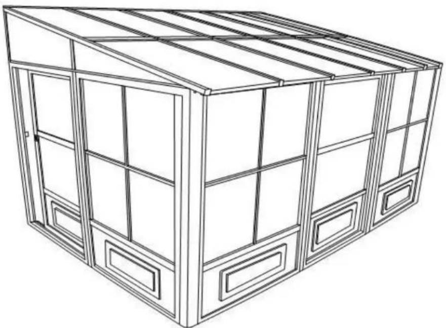
Line drawing of a modular cabinet or storage unit with multiple windows and doors (no text or symbols)DO NOT DESTROY THE BOXES UNTIL COMPLETELY ASSEMBLED PLEASE VERIFY THE CONTENT OF EACH BOX AGAINST THE LIST OF PARTS
Assembly by two or three adults is suggested.
Requires 96" clearance at the wall
Base Dimensions 144"x 94 1/2"
Largest Dimensions 144"x98 1/2"
(see pg.21)
APPROX.
DO NOT DESTROY THE BOXES UNTIL COMPLETELY ASSEMBLED
PLEASE VERIFY THE CONTENT OF EACH BOX AGAINST THE LIST OF PARTS
8ft x 12ft / 2.43m x 3.66m Solarium
Instruction Manual
Consult with your local governing authority / local municipal codes regarding installation of temporary structures before purchase or assembly. Some jurisdictions may require permits for, or otherwise regulate, installation and use.
IMPORTANT: RETAIN FOR FUTURE REFERENCE, READ CAREFULLY
For assistance with assembly, installation, parts, or customer service, contact Gazebo Penguin Customer
Service Department at the numbers listed below (English & French, Mon-Fri 8:00 AM to 4:00 PM EST):
Montreal: (514) 276-3485
Elsewhere in Canada and the US: 1-800-737-7174
WARNING:
- For outdoor use.
- Snow should be regularly cleared from the roof and not allowed to accumulate.
- Retain your proof of purchase for warranty purposes. Also keep the original boxes until the installation is complete and correct.
- The unit may take more than 4 hours and 3 people are required for this assembly.


PRIOR TO ASSEMBLY:
- Please don't destroy boxes until completely assembled.
- The foundation must be level, flat, and solid, such as concrete or asphalt.
- Keep away from overhead utility lines, tree branches, and other structures.
- Check for underground pipes or wires if digging or drilling is required.
- Do not install near roof lines or other structures that could shed snow, ice, or excessive rain run-off onto the roof top.
- Assemble the structure as close to its final location as possible.
- It is recommended to wear safety gloves, safety glasses, and hard hats for installation.
- Do not hang from, climb on, or stand on the structure or roof.
- Before assembly, read instructions and check that all parts are present in the boxes. If any parts are missing, refer to warranty information.
- A 6ft (1.8m) stepladder, Phillips screwdriver, tape measure, level, mallet, and a tarp to place parts on will be required for assembly (not included).
- Remove top protective film from roof panels prior to assembly; DO NOT remove bottom protective film until ready to insert roof panels, so as to identify which side is on top.
ANCHORING INSTRUCTIONS:
- Proper anchoring of the frame to the base and the wall is required for safety.
• Any structure not anchored securely has the potential to fly away during high wind causing damage and safety hazard.
• How the item is anchored, and the hardware and tools required, will vary based upon the set up location and are not provided. - Please check with your local hardware store if for the appropriate anchors for your surface.
- Do not anchor to pavers / pavement slabs because they are not a solid foundation.
• Periodically check the anchors to ensure they remain secure
CARE AND MAINTENANCE:
- In case of a defective or damaged part, or for any other questions concerning the product, please contact the manufacturer directly.
- Please have the parts list and part numbers on hand when ordering or requesting replacement parts.
ROOF PANELS:
• Gently clean with an environmentally-friendly soap solution and water using a sponge or washcloth.
- Do not use abrasive materials, wire brushes, chemicals, harsh cleaners, or bleach.
- Rinse using a garden hose and air dry. If removed, ensure thoroughly dry prior to storage.
- Do not use pressure washer.
STRUCTURE:
• Gently clean with an environmentally-friendly soap solution and water using a sponge or washcloth.
- Do not use abrasive materials, wire brushes, chemicals, harsh cleaners, or bleach.
- Rinse using a garden hose and air dry.
- Do not use pressure washer.
- If there are nicks, chips, and/or scratches see the part # of the paint in the parts list to obtain a matching touch-up paint.
MAINTENANCE NOTES
- In case of a defective or damaged part, or for any other questions concerning the product, please contact the manufacturer directly.
- Please have the parts list and part numbers on hand when ordering or requesting replacement parts.
- The product should not be installed adjacent to trees or a sloped roof. Snow and ice may slide onto the roof and cause it to collapse.
- While the product is designed to stay assembled year long, the roof must be kept free of accumulation of snow.

natural_image
Simple line drawing of a barn with trees and a cross symbol (no text or labels)ONE YEAR LIMITED WARRANTY
This product has been designed and manufactured to meet the highest standards of quality and durability. Subject to the Conditions for Exercising the Warranty and the Limitations on the Warranty set forth below, it is warranted to be free of material and manufacturing defects for a period of one year from the date of purchase. Missing and damage due to transportation is not covered by the manufacture warranty. Should the product become damaged, or the warranty period has expired, please contact Gazebo Penguin Customer Service Department for a complete schedule of replacement parts and prices.
CONDITIONS FOR EXERCISING THE WARRANTY
The warranty only applies to the original purchaser with the bill.
In order to properly exercise your warranty, please comply with the following:
Carefully inspect the contents of the carton for missing or damaged components. Should you discover damaged or missing parts, do not return the product to the place of purchase, but contact Gazebo Penguin Customer Service Department at the numbers listed below:
Montreal: (514) 276-3485
Elsewhere: 1-800-737-7174
You can also find a claim form to fill out online:
https://abrispenguin.com/assemblyinstructions/
NOTE: Damages/missing parts must be reported within 30 days of delivery. If claimed after your request might be rejected.
LIMITATIONS ON THE WARRANTY
- The product is not warranted against damages due to vandalism, abuse, falling or thrown objects, or accumulation of snow.
- The product is not warranted against damages due to extreme weather conditions, such as thunderstorms, hail, strong wind or snow storms, or any other acts of God.
- Leaking due to heavy rain may happen, please refer to the instruction manual for window positions and information on how to evacuate the water.
- The product is only warranted in the event it is installed in accordance with the Gazebo Penguin's written instructions enclosed with the product.
- The product is not warranted in the event it has been improperly anchored.
- We reserve the right to replace or repair any defective product or parts at our discretion.
- No change to the unit is allowed. This will void your warranty.
TOOLS REQUIRED:
- Screwdriver (Philips #2)
- Knife
- File (smooth)
- Needle-nosed pliers
- Rubber mallet
- Step ladder (minimum 6' in height)
- Spatula
- Power drill
- Tube of silicon
- Drill bit 5/16" cement (according to surface)
BEFORE STARTING:
Ensure that you have a solid base, such as concrete or wooden deck, not slanted more than 1" per 8'. Avoid installing unit adjacent to trees or a sloped roof, as snow and ice may slide onto the solarium and cause it to collapse.
Please don't destroy boxes until completely assembled.
text_image
E-3 A-3 K-3 E-3 A-3 K-3 B-3 D-3 D-3 A-3 B-3 D-3 A-3 E-3 Eoped the letely assembledSTEP #1
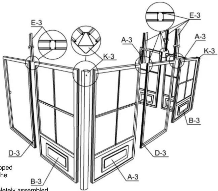
Decide the position of the door frames before assembly according to where you intend to slide the door. At the front of the solarium, use frame D3 for the opening of the door and B3 for the direction of the door when open. Use E3 between frame ends and use two (2) K3 joints for corners.
NOTE:
When placing the door frame opening, make sure the inserts on the frame are on the inside and on the upper half of the frame of the solarium because the door will be set on the inside due to clearance.
NOTE:
When sliding the connectors, shake the frame so that they will slide easily. Do not use tools to force. If needed, clean the paint with a file and make sure the ends of the frame and joints are not bent or warped. If so, use the needle-nosed pliers to straighten
STEP #2
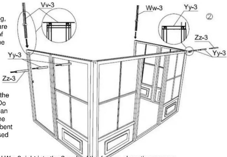
Slide the vertical guides Vv-3 left and Ww-3 right into the 2 ends of the frames along the grooves, shaking while sliding for easier movement. Next, slide two (2) Yy-3 and one (1) Zz-3 from left side to right on top of the frame. The groove should be towards the interior of the unit. Repeat from right side with two (2) YY-3 and one (1) Zz-3 and space evenly.
text_image
Vv-3 Ww-3 Yy-3 ② Zz-3 Yy-3 Yy-3 Zz-3 Yy-3 Ww-3 right into the 2 end of the fence along the groves the do an e pent ed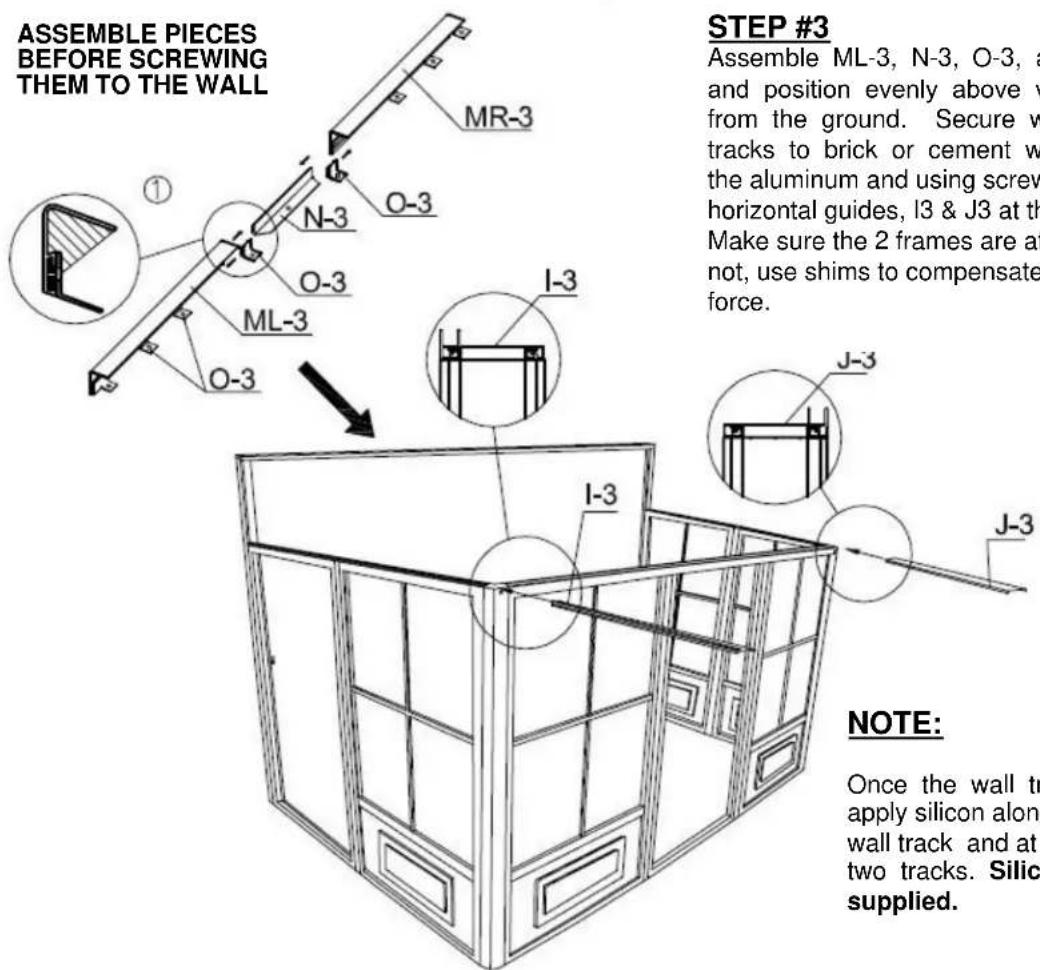
text_image
ASSEMBLE PIECES BEFORE SCREWING THEM TO THE WALL STEP #3 Assemble ML-3, N-3, O-3, a and position evenly above w from the ground. Secure w tracks to brick or cement w the aluminum and using screw horizontal guides, I3 & J3 at th Make sure the 2 frames are at not, use shims to compensate force. NOTE: Once the wall tr apply silicon along wall track and at two tracks. Silic supplied.STEP #3
Assemble ML-3, N-3, O-3, and MR-3 as shown and position evenly above vertical guides, at 96" from the ground. Secure wall track and vertical tracks to brick or cement wall by drilling through the aluminum and using screws Xx-3. Insert the 2 horizontal guides, I3 & J3 at the top of the frame. Make sure the 2 frames are at the correct level, if not, use shims to compensate. Do not use tools to force.
NOTE:
Once the wall track is in place, apply silicon along the top of the wall track and at the joint of the two tracks. Silicon is not supplied.
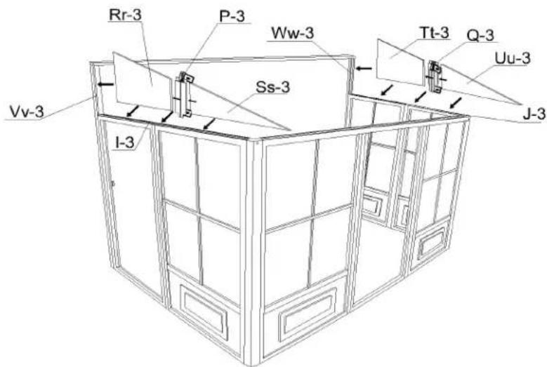
STEP #4
Set polycarbonate exposed side on the outside over horizontal left guide I-3, use one (1) Rr-3 panel, one (1) P-3 joint and one (1) Ss-3 panel, then do the right side with one (1) Tt-3 panel, one (1) Q-3 joint and one (1) Uu-3 panel over the J-3 horizontal panel. Secure P-3 and Q-3 to I-3 and J-3 respectively with self-tapping screws (PQ-3).
text_image
Rr-3 P-3 Ww-3 Tt-3 Q-3 Uu-3 Vv-3 Ss-3 J-3 I-3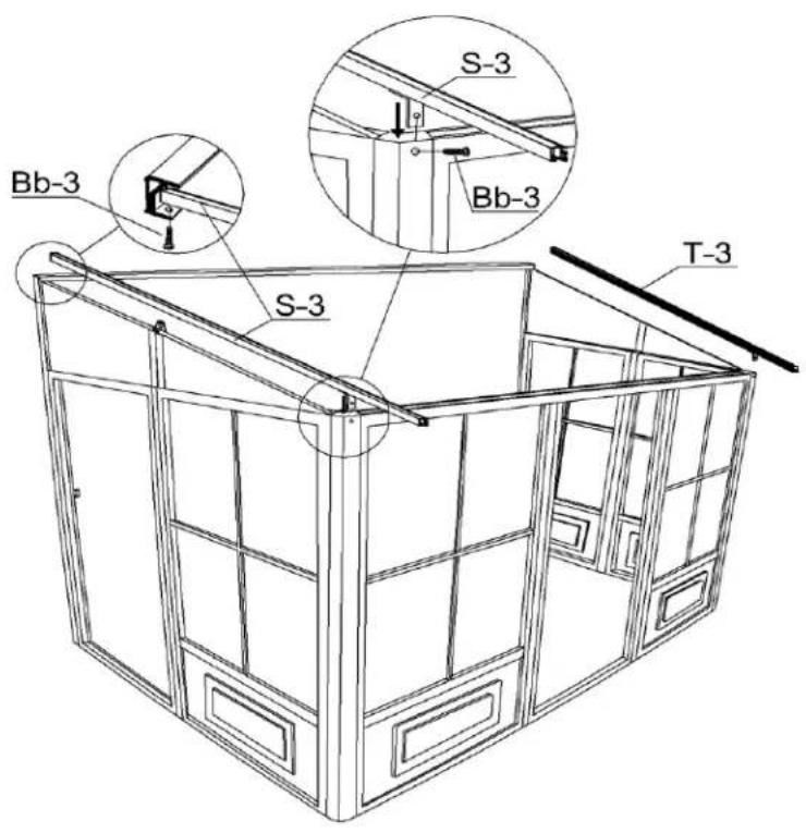
text_image
S-3 Bb-3 S-3 Bb-3 T-3STEP #5
Set right rafter T-3 over last bracket then secure it with Bb-3 screw and continue screwing through joint K-3 with the Bb-3 screw. Secure to Q-3 bracket with self-tapping screw (PQ-3). Repeat on left side with rafter S-3.
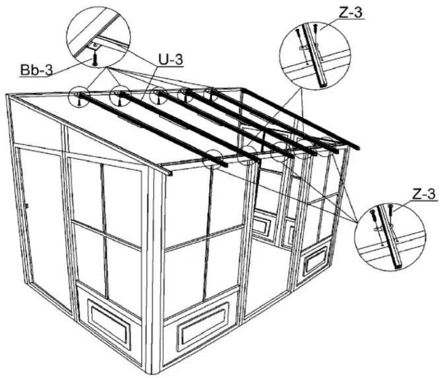
STEP #6
Set U-3 rafters over the middle of each panel with Bb-3 screws at the top and two (2) Z-3 screws over the brackets on frame manually. Set U-3 rafter on each joint and use Z-3 screws manually. Do not use power drill.
text_image
Bb-3 U-3 Z-3 Z-3STEP #7
Remove protective film from two (2) sides of each panel and make sure the top side of the panel faces the sunlight. Insert and slide on the top groove of the rafters all the way to the end. Pp-3 should go first and last with the Qq-3 panels in between.

text_image
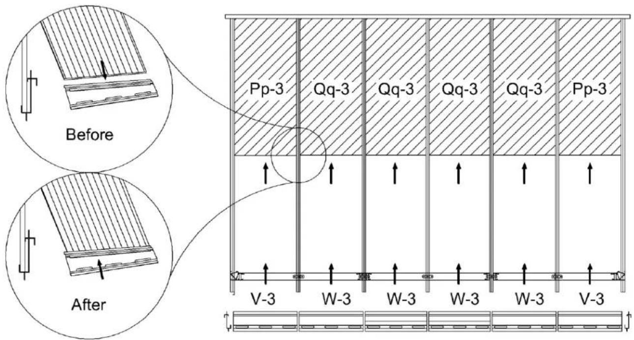
S-3 U-3 U-3 U-3 U-3 U-3 T-3 Pp-3 Qq-3 Qq-3 Qq-3 Qq-3 Pp-3STEP #8
Insert the aluminum middle roof joint between the rafters, making sure the slotted holes are at the bottom. Slide into upper and lower grooves of the rafters then slide all the way into the panels. Make sure the panels are inside the aluminum middle roof joint groove. Insert a V-3 at either end, then insert all W-3 and then the remaining V-3. Tap gently with rubber mallet if needed.
text_image
Before After Pp-3 Qq-3 Qq-3 Qq-3 Qq-3 Pp-3 V-3 W-3 W-3 W-3 W-3 V-3STEP #9
Insert the second row of panels into the lower groove on the rafter. Slide panels until they reach the aluminum pieces between the panels and gently tap on the panel to guide it into the aluminum groove. Use a spatula if needed to make it fit. Insert two (2) Pp-3 on either end, then insert the Qq-3 panels.
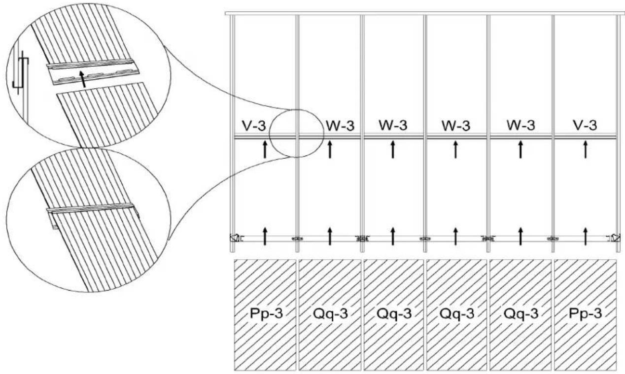
text_image
V-3 W-3 W-3 W-3 W-3 V-3 Pp-3 Qq-3 Qq-3 Qq-3 Qq-3 Pp-3STEP #10
Starting at either end, add X-3 edging and one (1) R-3 bracket and screw with Bb-3 manually, do not use power drill. Add Y-3 edging and repeat until you reach the end, then add the X-3 edging.
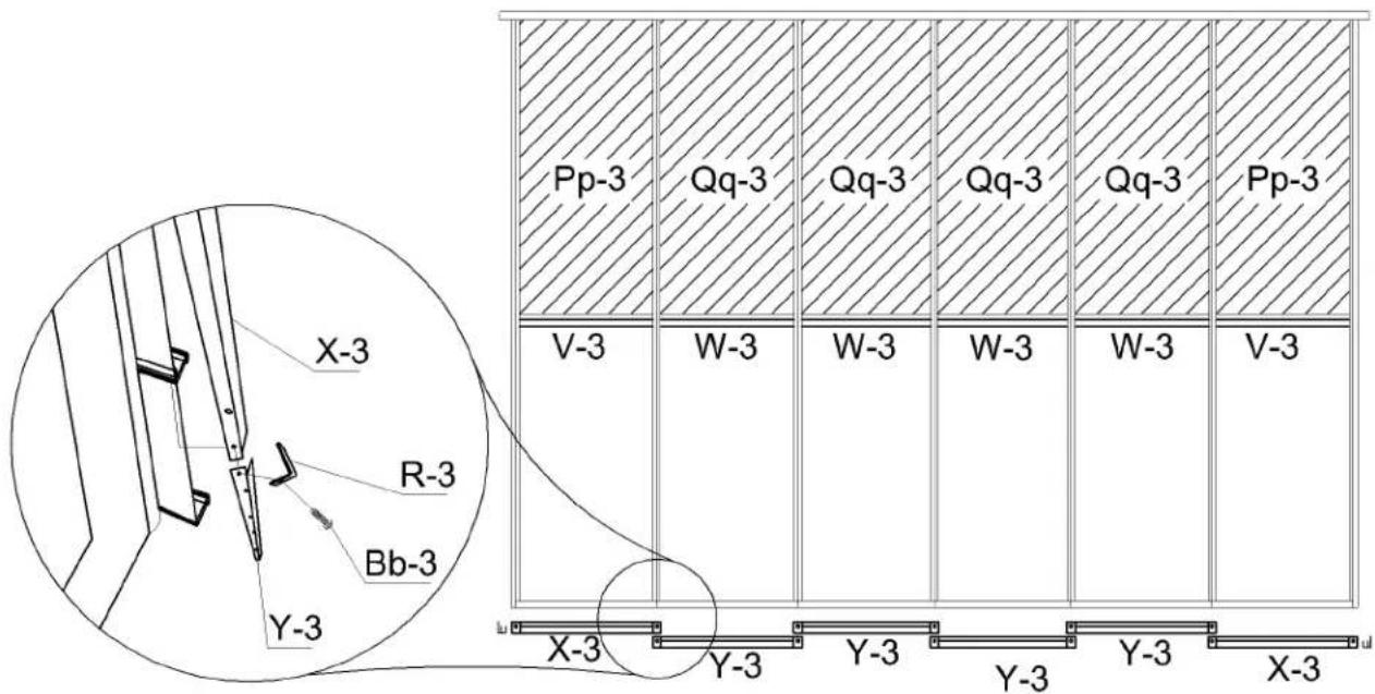
text_image
X-3 R-3 Bb-3 Y-3 Pp-3 Qq-3 Qq-3 Qq-3 Qq-3 Pp-3 V-3 W-3 W-3 W-3 W-3 V-3 X-3 Y-3 Y-3 Y-3 Y-3 X-3STEP #11
On the inside of the solarium under each rafter there are two rows of inserts with threads. Start the upper row with a Jj-3 at either end and screw it with Ff3 and in between the Kk-3 panels. Use Ff-3 screws at the lower row LI-3 at the 2 ends then the others in between the Mm-3 panels. Make sure screws are manually tight.
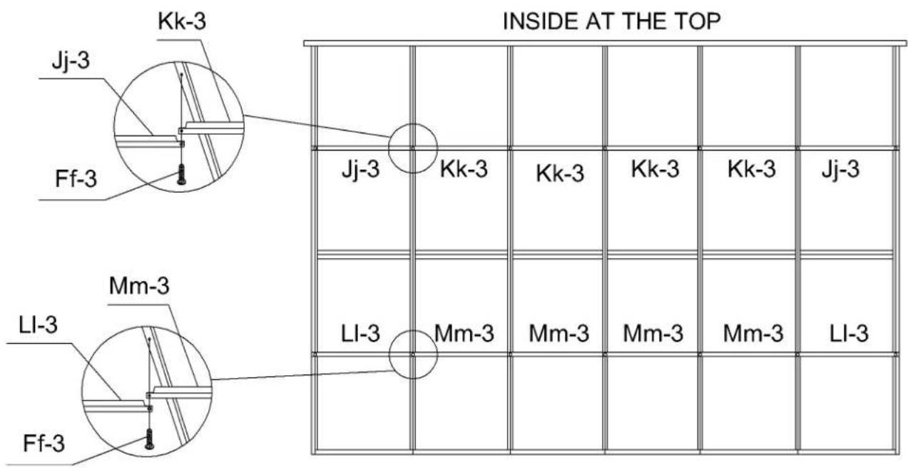
text_image
INSIDE AT THE TOP Jj-3 Kk-3 Ff-3 Jj-3 Kk-3 Kk-3 Kk-3 Jj-3 Mm-3 LI-3 Mm-3 Mm-3 Mm-3 LI-3 Mm-3 Mm-3 Mm-3 Mm-3 LI-3STEP #12
DOOR UNIT(S) MUST BE ASSEMBLED INSIDE OF SOLARIUM.
Slide upper door track F-3 into wheels of sliding door C-3. Slide lower door track G-3 and make sure inserts are close enough to the frame to attach. Use bolt Bb-3 to affix the plastic stopper H-3 on each end of top door rail F-3. Use Oo-3 screws to affix upper door rail and cap Nn-3, at each end of top rail door.
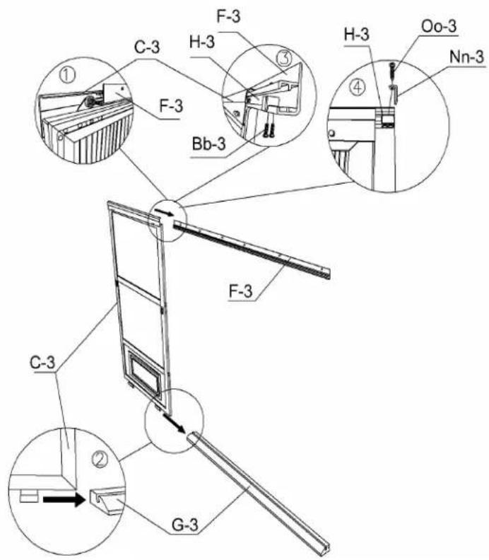
text_image
C-3 F-3 H-3 ① ③ Bb-3 H-3 Oo-3 Nn-3 ④ F-3 C-3 G-3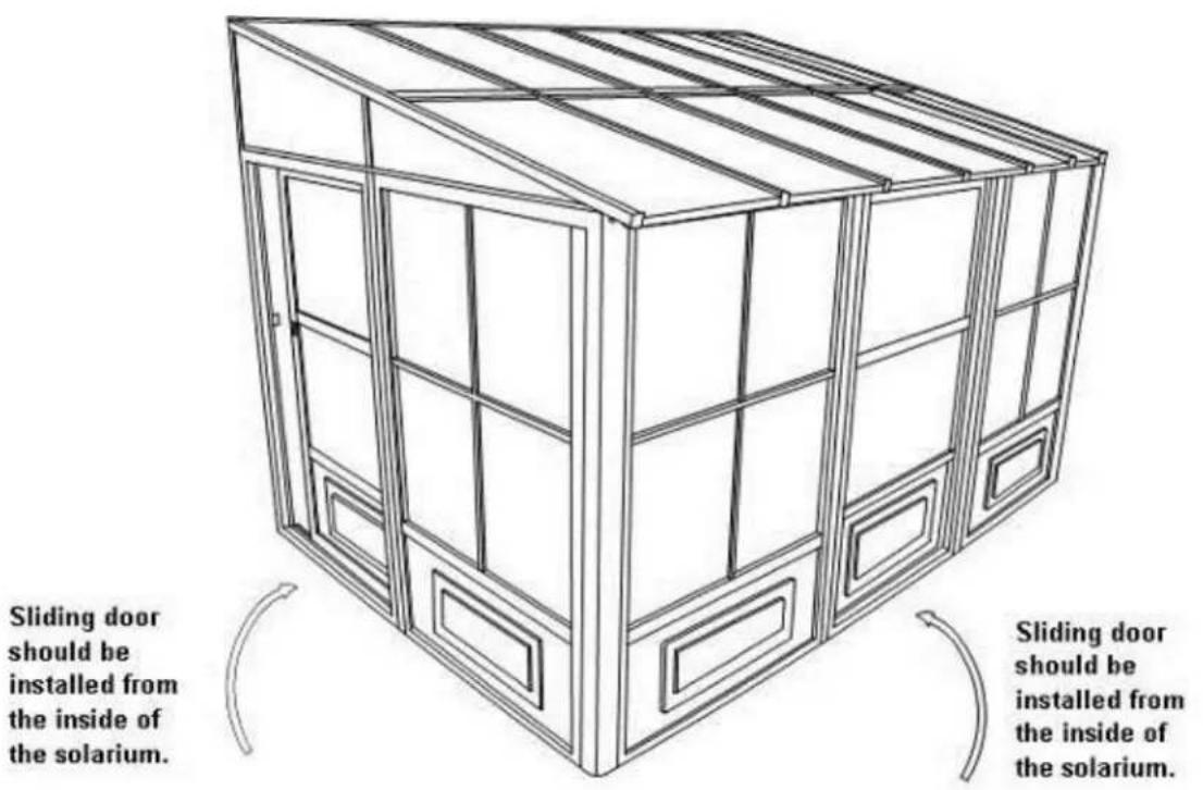
text_image
Sliding door should be installed from the inside of the solarium. Sliding door should be installed from the inside of the solarium.STEP #13
Lift up door and track inside of solarium then set it over the door opening by screwing at the top. First use bolts (Ww) and washers (Gg-3) on the inside and female bolts (Cc-3-2) on the outside for the top assembly. See diagram below. Attach lower track with bolts (Cc-3) and washers (Gg-3). Set up door latch on the side required for your door to lock, adjust latch as required.
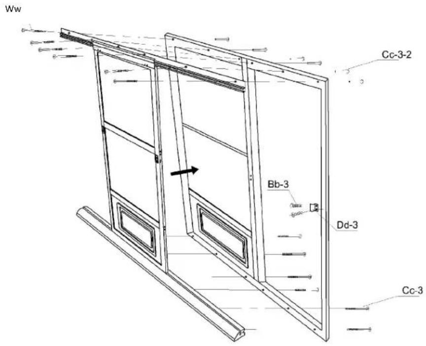
text_image
Ww Cc-3-2 Bb-3 Dd-3 Cc-3STEP #14
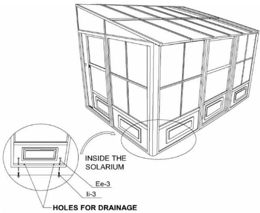
Anchor the solarium to the deck or floor securely using screws and shields supplied. See diagram below.
text_image
INSIDE THE SOLARIUM Ee-3 li-3 Holes FOR DRAINAGE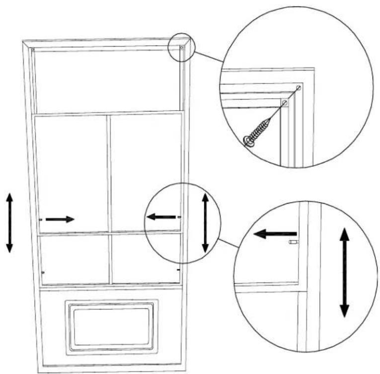
text_image
Technical diagram showing door frame structure with dimension annotations and magnified detail viewsSPECIAL NOTES
To remove a screen, remove the two (2) screws at the top of the frame then pull sideways to the opposite end of the handles to remove. To remove wind panels, push or pull to one side, making sure that locking pin is not locked then remove panels gently, panels are easy to remove.
NOTE:
This unit is not waterproof. For best protection against rain, close the windows of each frame with the outside window in the center, and the inside window at the top.
CLEANING INSTRUCTIONS:
Use only mild or warm soapy water, no strong or abrasive cleaning products. Be sure to remove heavy snow and/or ice.
WARNING:
1) Do not use a BBQ or any other flammable product inside the solarium.
2) Remove snow from the roof.
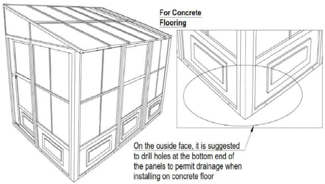
\*Suggestions
The below mentioned are only suggestions in order to permit drainage, these will vary depending on your flooring – material, flatness and slope.
text_image
For Concrete Flooring On the outside face, it is suggested to drill holes at the bottom end of the panels to permit drainage when installing on concrete floor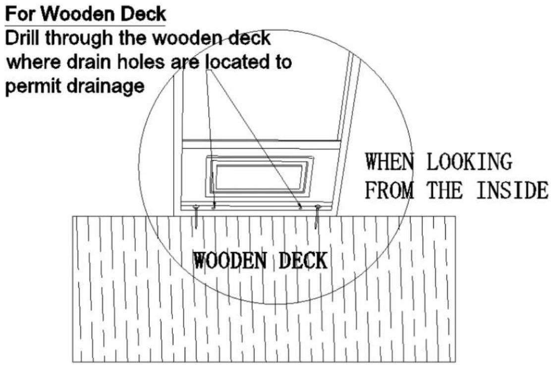
text_image
For Wooden Deck Drill through the wooden deck where drain holes are located to permit drainage WHEN LOOKING FROM THE INSIDE WOODEN DECKSOLARIUM W1207 SAND (see page 17 for Slate parts)
| DESCRIPTION | PACKED IN BOX | QTY | DRAWING | DESCRIPTION | PACKED IN BOX | QTY | DRAWING | ||
| 10-496REGULARFRAMEA-3 | 2 | 2 |  | 10-497FRAME NEXTTO DOORB-3(Has moreholes) | 2 | 1 |  | ||
| 3 | 1 | 3 | 1 | ||||||
| 10-498SLIDING DOORC-3 | 2 | 1 |  | 10-499SLIDING DOORFRAME D-3 | 2 | 1 |  | ||
| 3 | 1 | 3 | 1 | ||||||
| 11-544CONNECTINGPIECEE-3 | 4 | 8 |  | 11-545TOP DOORRAILF-3 | 4 | 2 |  | ||
| 11-546BOTTOM DOORRAILG-3 | 4 | 2 |  | 08-138PLASTICSTOPPERH-3 | 5 | 4 |  | ||
| 10-500LEFT SIDERECEIVERI-3 | 4 | 1 |  | 10-501RIGHT SIDERECEIVERJ-3 | 4 | 1 |  | ||
| 10-502CORNERCONNECTORK-3 | 4 | 2 |  | 10-503TRACKML-3 | 4 | 1 |  | ||
| 10-504TRACKMR-3 | 4 | 1 |  | 10-505TRACK JOINTN-3 | 5 | 1 |  | ||
| 10-506RAFTERBRACKETO-3 | 5 | 4 |  | 10-507LEFT GABLEJOINTP-3 | 5 | 1 | 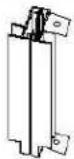 | ||
| 10-508RIGHT GABLEJOINTQ-3 | 5 | 1 |  | 10-509ROOF RAFTERCAPR-3 | 5 | 7 |  | ||
| DESCRIPTION | PACKED IN BOX | QTY | DRAWING | DESCRIPTION | PACKED IN BOX | QTY | DRAWING |
| 10-510 LEFT SIDE RAFTER S-3 | 4 | 1 |  | 10-511 RIGHT SIDE RAFTER T-3 | 4 | 1 |  |
| 10-512 REGULAR RAFTER U-3 | 4 | 5 | 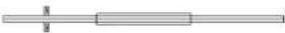 | 10-513 MIDDLE ROOF JOINT V-3 | 5 | 2 | 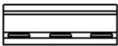 |
| 10-514 MIDDLE ROOF JOINT W-3 | 5 | 4 | 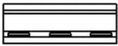 | 10-515 EDGING X-3 | 5 | 2 |  |
| 10-516 EDGING Y-3 | 5 | 4 |  | 08-156 SCREW Z-3 | 5 | 10 |  (M4*16mm) (M4*16mm) |
| 08-158 BOLT Bb-3 | 5 | 28 |  (M6*16mm) (M6*16mm) | 08-161 BOLT Cc-3 | 5 | 12 |  (M6*70mm) (M6*70mm) |
| 12-037 FEMALE BOLT Cc-3-2 | 5 | 12 |  M6*60mm M6*60mm | 08-169 LEFT DOOR LATCH Dd-L-3 | 5 | 2 |  |
| 08-165 RIGHT DOOR LATCH Dd-R-3 | 5 | 2 |  | 08-167 SCREW Ee-3 | 5 | 10 |  (M6*100mm) (M6*100mm) |
| 08-168 BOLT Ff-3 | 5 | 16 |  (M6*12mm) (M6*12mm) | 08-187 WASHER Gg-3 | 5 | 22 | (0CTA) |
| 08-193 PLASTIC PLUG li-3 | 5 | 10 | (ZVCR) | 10-517 END ROOF CROSS BAR Jj-3 | 5 | 2 | 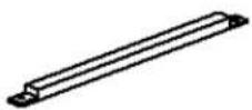 |
| 10-518 REGULAR ROOF CROSSBAR Kk-3 | 5 | 4 |  | 10-519 ROOF TOP REINFORCE LI-3 | 5 | 2 |  |
| 10-520 ROOF TOP REINFORCE Mm-3 | 5 | 4 | 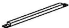 | 08-134 UPPER DOOR RAIL END CAP Nn | 5 | 4 | 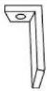 |
| 08-135 SCREW Oo-3 | 5 | 8 | 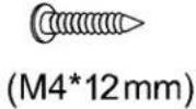 | 10-521 (51 1⁄2" X 24 1⁄2") LEFT+RIGHT ROOF PANEL Pp-3 | 1 | 4 |  |
| 10-522 (51 1⁄2" X 23") REGULAR ROOF PANEL Qq-3 | 1 | 8 |  | 10-523 LEFT BACK GABLE PANEL Rr-3 | 1 | 1 |  |
| 10-524 LEFT FRONT GABLE PANEL Ss-3 | 1 | 1 |  | 10-525 RIGHT BACK GABLE PANEL Tt-3 | 1 | 1 |  |
| 10-526 RIGHT FRONT GABLE PANEL Uu-3 | 1 | 1 |  | 10-527 LEFT WALL GUIDE Vv-3 | 4 | 1 |  |
| 10-528 RIGHT WALL GUIDE Ww-3 | 4 | 1 |  | 10-529 SCREW FOR FIXING TO WALL Xx-3 | 5 | 18 |  |
| 10-530 REGULAR TOP FILLER Yy-3 | 5 | 4 |  | 10-531 END TOP FILLER Zz-3 | 5 | 2 |  |
| 13-045 SELF-TAPPING SCREW PQ-3 | 5 | 4 |  | 12-047 BOLT Ww | 5 | 12 |  M5*15mm M5*15mm |
| AVAILABLE REPLACEMENT PARTS | |||
| DESCRIPTION | DRAWING | DESCRIPTION | DRAWING |
| 10-435-12PVC WINDOW(in frame) |  | 85-014REPLACEMENT SCREENING (no frame) |  |
| 12-176-12PVC WINDOW for HALF FRAME A-3 1/2 | 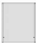 | 85-417-SROUND SPLINE FOR SCREENING |  |
| 10-493PVC WINDOW(replacement material only) |  | 11-824-12BOTTOM PLASTIC PANEL (for wall panels) |  |
| 85-417-P ROUND SPLINE FOR PVC WINDOW |  | 11-825-12BOTTOM PLASTIC PANEL (for doors) |  |
| 15-123-12PIN FOR PVC WINDOW |  | 12-173-12BOTTOM PLASTIC PANEL FOR HALF FRAME A-3 1/2 |  |
| 13-055PC WINDOW (for sliding door) |  | 15-097-12DOOR WHEEL ASSEMBLY |  |
| 12-174-12MOSQUITO SCREEN (in frame) |  | 10-458REPLACEMENT WEATHERSTRIP 124" |  |
| 12-175-12MOSQUITO SCREEN FOR HALF FRAME A-3 1/2 |  | 15-126-12MOUNTING BRACKET FOR RAFTER (U-3) |  |
*NOT INCLUDED IN THE BOX
| DESCRIPTION | COLOUR | PART # |
| SPRAY PAINT | SAND | 11-699 |
| PAINT PEN | 18-245 |
SOLARIUM W1207 SLATE
| DESCRIPTION | PACKED IN BOX | QTY | DRAWING | DESCRIPTION | PACKED IN BOX | QTY | DRAWING | |
| 10-496REGULARFRAMEA-3 | 2 | 2 |  | 10-497FRAME NEXTTO DOORB-3(Has moreholes) | 2 | 1 |  | |
| 3 | 1 | 3 | 1 | |||||
| 10-498SLIDING DOORC-3 | 2 | 1 |  | 10-499SLIDING DOORFRAME D-3 | 2 | 1 |  | |
| 3 | 1 | 3 | 1 | |||||
| 11-544CONNECTINGPIECEE-3 | 4 | 8 |  | 11-545TOP DOORRAILF-3 | 4 | 2 | 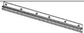 | |
| 11-546BOTTOM DOORRAILG-3 | 4 | 2 |  | 08-138PLASTICSTOPPERH-3 | 5 | 4 |  | |
| 10-500LEFT SIDERECEIVERI-3 | 4 | 1 | 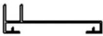 | 10-501RIGHT SIDERECEIVERJ-3 | 4 | 1 |  | |
| 10-502CORNERCONNECTORK-3 | 4 | 2 |  | 10-503TRACKML-3 | 4 | 1 | 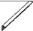 | |
| 10-504TRACKMR-3 | 4 | 1 | 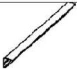 | 10-505TRACK JOINTN-3 | 5 | 1 |  | |
| 10-506RAFTERBRACKETO-3 | 5 | 4 |  | 10-507LEFT GABLEJOINTP-3 | 5 | 1 |  | |
| 10-508RIGHT GABLEJOINTQ-3 | 5 | 1 |  | 10-509ROOF RAFTERCAPR-3 | 5 | 7 |  | |
| 10-510 LEFT SIDE RAFTER S-3 | 4 | 1 |  | 10-511 RIGHT SIDE RAFTER T-3 | 4 | 1 |  | |
| 10-512 REGULAR RAFTER U-3 | 4 | 5 |  | 10-513 MIDDLE ROOF JOINT V-3 | 5 | 2 |  | |
| 10-514 MIDDLE ROOF JOINT W-3 | 5 | 4 |  | 10-515 EDGING X-3 | 5 | 2 |  | |
| 10-516 EDGING Y-3 | 5 | 4 |  | 08-156 SCREW Z-3 | 5 | 10 |  (M4*16mm) (M4*16mm) | |
| 08-158 BOLT Bb-3 | 5 | 28 |  (M6*16mm) (M6*16mm) | 08-161 BOLT Cc-3 | 5 | 12 |  (M6*70mm) (M6*70mm) | |
| 12-037 FEMALE BOLT Cc-3-2 | 5 | 12 |  M6*60mm M6*60mm | 08-169 LEFT DOOR LATCH Dd-L-3 | 5 | 2 |  | |
| 08-165 RIGHT DOOR LATCH Dd-R-3 | 5 | 2 |  | 08-167 SCREW Ee-3 | 5 | 10 |  (M6*100mm) (M6*100mm) | |
| 08-168 BOLT Ff-3 | 5 | 16 |  (M6*12mm) (M6*12mm) | 08-187 WASHER Gg-3 | 5 | 22 | ||
| 08-193 PLASTIC PLUG li-3 | 5 | 10 | 10-517 END ROOF CROSS BAR Jj-3 | 5 | 2 |  | ||
| 10-518 REGULAR ROOF CROSSBAR Kk-3 | 5 | 4 |  | 10-519 ROOF TOP REINFORCE LI-3 | 5 | 2 |  | |
| 10-520 ROOF TOP REINFORCE Mm-3 | 5 | 4 |  | 08-134 UPPER DOOR RAIL END CAP Nn | 5 | 4 |  | |
| 08-135 SCREW Oo-3 | 5 | 8 |  | 10-521 (51 1⁄2" X 24 1⁄2") LEFT+RIGHT ROOF PANEL Pp-3 | 1 | 4 |  | |
| 10-522 (51 1⁄2" X 23") REGULAR ROOF PANEL Qq-3 | 1 | 8 |  | 10-523 LEFT BACK GABLE PANEL Rr-3 | 1 | 1 |  | |
| 10-524 LEFT FRONT GABLE PANEL Ss-3 | 1 | 1 |  | 10-525 RIGHT BACK GABLE PANEL Tt-3 | 1 | 1 |  | |
| 10-526 RIGHT FRONT GABLE PANEL Uu-3 | 1 | 1 |  | 10-527 LEFT WALL GUIDE Vv-3 | 4 | 1 |  | |
| 10-528 RIGHT WALL GUIDE Ww-3 | 4 | 1 |  | 10-529 SCREW FOR FIXING TO WALL Xx-3 | 5 | 18 |  | |
| 10-530 REGULAR TOP FILLER Yy-3 | 5 | 4 |  | 10-531 END TOP FILLER Zz-3 | 5 | 2 |  | |
| 13-045 SELF-TAPPING SCREW PQ-3 | 5 | 4 |  | 12-047 BOLT Ww | 5 | 12 |  M5*15mm M5*15mm | |
| AVAILABLE REPLACEMENT PARTS | |||
| DESCRIPTION | DRAWING | DESCRIPTION | DRAWING |
| 10-435-32PVC WINDOW(in frame) |  | 85-014REPLACEMENT SCREENING (no frame) |  |
| 12-176-32PVC WINDOW for HALF FRAME A-3 1/2 |  | 85-417-SROUND SPLINE FOR SCREENING |  |
| 10-493PVC WINDOW(replacement material only) |  | 11-824-32BOTTOM PLASTIC PANEL (for wall panels) |  |
| 85-417-P ROUND SPLINE FOR PVC WINDOW |  | 11-825-32BOTTOM PLASTIC PANEL (for doors) |  |
| 15-123-32PIN FOR PVC WINDOW |  | 12-173-32BOTTOM PLASTIC PANEL FOR HALF FRAME A-3 1/2 |  |
| 13-055PC WINDOW (for sliding door) |  | 15-097-32DOOR WHEEL ASSEMBLY |  |
| 12-174-32MOSQUITO SCREEN (in frame) |  | 10-458REPLACEMENT WEATHERSTRIP 124" |  |
| 12-175-32MOSQUITO SCREEN FOR HALF FRAME A-3 1/2 |  | 15-126-32MOUNTING BRACKET FOR RAFTER (U-3) |  |
*NOT INCLUDED IN THE BOX
| DESCRIPTION | COLOUR | PART # |
| SPRAY PAINT | SALTE | 18-125 |
| PAINT PEN | 18-126 |
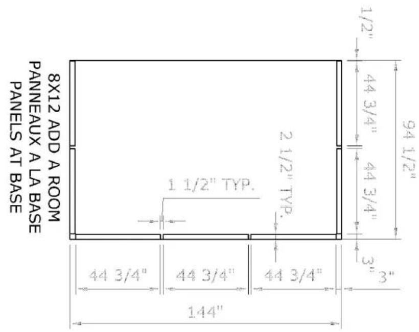
Note: The Dimensions are approximate.
text_image
8X12 ADD A ROOM PANNEAUX A LA BASE PANELS AT BASE 44 3/4" 1 1/4" 44 3/4" 44 3/4" 2 1/2" TYP. 1 1/2" TYP. 94 1/2" 1/2" 44 3/4" 44 3/4" 3" 3"