
41215-12 - Tent Gazebo Penguin - Free user manual and instructions
Find the device manual for free 41215-12 Gazebo Penguin in PDF.


| Product Type | Outdoor Solarium / Tent |
| Brand | Gazebo Penguin |
| Model | 41215-12 (Sand) / 41215-32 (Slate) |
| Base Dimensions | 12 ft 12 in x 15 ft 6 in (3.66 m x 4.57 m) |
| Largest Dimensions | 13 ft 6 in x 16 ft 11 in |
| Overall Height | 110 in (approx. 9.17 ft) |
| Material | Aluminum frame, polycarbonate roof panels, PVC windows |
| Color Options | Sand, Slate |
| Assembly Required | Yes, three adults recommended; 4+ hours assembly time |
| Foundation Requirement | Level, flat, solid surface (concrete, asphalt, or wooden deck) |
| Anchoring | Required; user-provided anchors appropriate for surface |
| Door Type | Two sliding doors (left or right opening) |
| Windows | PVC windows with screens; sliding operation |
| Roof Material | Polycarbonate panels with aluminum framing |
| Water Resistance | Not waterproof; designed for rain drainage with proper window positioning |
| Snow Load Capacity | Snow must be regularly cleared from roof; not designed for heavy accumulation |
| Care Instructions | Clean with mild soap and water; no abrasive materials, bleach, or pressure washer |
| Spare Parts Availability | Yes, listed in manual; contact manufacturer for replacements |
| Warranty | One-year limited warranty against material and manufacturing defects |
| Safety Precautions | Keep away from overhead lines, trees; do not climb on structure; anchor securely |
Frequently Asked Questions - 41215-12 Gazebo Penguin
User questions about 41215-12 Gazebo Penguin
0 question about this device. Answer the ones you know or ask your own.
Ask a new question about this device
Download the instructions for your Tent in PDF format for free! Find your manual 41215-12 - Gazebo Penguin and take your electronic device back in hand. On this page are published all the documents necessary for the use of your device. 41215-12 by Gazebo Penguin.
USER MANUAL 41215-12 Gazebo Penguin
GAZEBO penguin inc.
4660 HICKMORE ST,
MONTREAL, QUEBEC
H4T 1K2
TEL: 1-514-276-3485, 1-800-737-7174
Email: customerservice@gazebopenguin.com
PLEASE READ IN ITS ENTIRETY BEFORE INSTALLATION
41215-12 SAND 41215-32 SLATE
12 X 15 SOLARIUM
PLEASE READ IN ITS ENTIRETY BEFORE INSTALLATION
ASSEMBLY INSTRUCTIONS
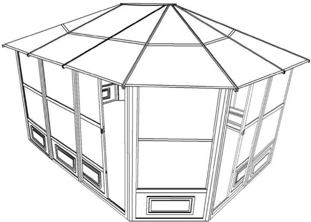
DO NOT DESTROY THE BOXES UNTIL COMPLETELY ASSEMBLED PLEASE VERIFY THE CONTENT OF EACH BOX AGAINST THE LIST OF PARTS
Three adults required for assembly
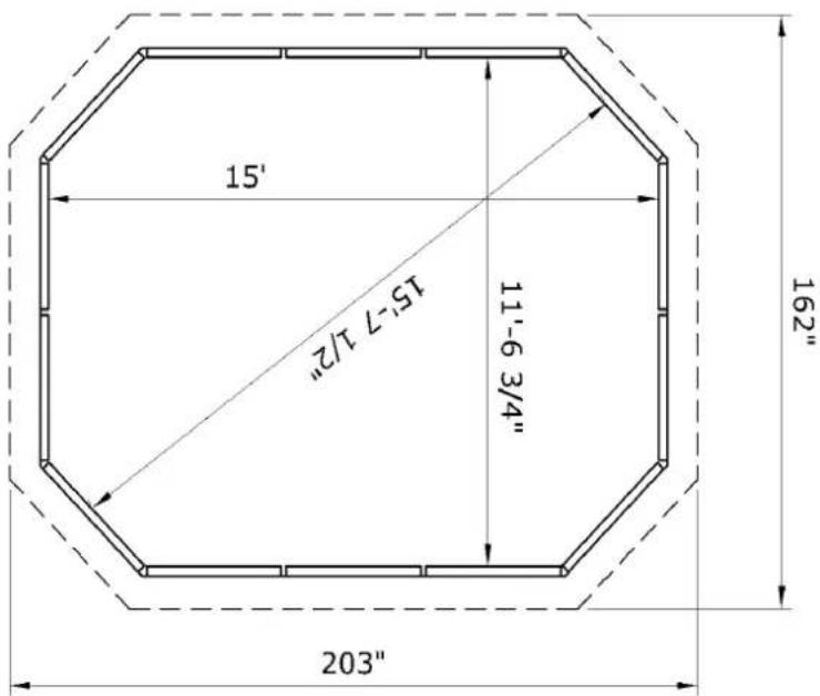
Base Dimensions 12' 1/2 "x15'6", Largest Dimensions 13'6"x16'11" Overall Height 110" (see pg.21)
APPROX.
DO NOT DESTROY THE BOXES UNTIL COMPLETELY ASSEMBLED PLEASE VERIFY THE CONTENT OF EACH BOX AGAINST THE LIST OF PARTS
12ft x 15ft / 3.66m x 4.57m Solarium
Instruction Manual
IMPORTANT: RETAIN FOR FUTURE REFERENCE, READ CAREFULLY
Consult with your local governing authority / local municipal codes regarding installation of temporary structures before purchase or assembly. Some jurisdictions may require permits for, or otherwise regulate, installation and use.
For assistance with assembly, installation, parts, or customer service, contact Gazebo Penguin Customer
Service Department at the numbers listed below (English & French, Mon-Fri 8:00 AM to 4:00 PM EST):
Montreal: (514) 276-3485
Elsewhere in Canada and the US: 1-800-737-7174
WARNING:
- For outdoor use.
- Snow should be regularly cleared from the roof and not allowed to accumulate.
- Retain your proof of purchase for warranty purposes. Also keep the original boxes until the installation is complete and correct.
- The unit may take more than 4 hours and 3 people are required for this assembly.
PRIOR TO ASSEMBLY:
- Please don't destroy boxes until completely assembled.
- The foundation must be level, flat, and solid, such as concrete or asphalt.
- Keep away from overhead utility lines, tree branches, and other structures.
- Check for underground pipes or wires if digging or drilling is required.
- Do not install near roof lines or other structures that could shed snow, ice, or excessive rain run-off onto the roof top.
- Assemble the structure as close to its final location as possible.
- It is recommended to wear safety gloves, safety glasses, and hard hats for installation.
- Do not hang from, climb on, or stand on the structure or roof.
- Before assembly, read instructions and check that all parts are present in the boxes. If any parts are missing, refer to warranty information.
- A 6ft (1.8m) stepladder, Phillips screwdriver, tape measure, level, mallet, and a tarp to place parts on will be required for assembly (not included).
- Remove top protective film from roof panels prior to assembly; DO NOT remove bottom protective film until ready to insert roof panels, so as to identify which side is on top.
ANCHORING INSTRUCTIONS:
- Proper anchoring of the frame to the base and the wall is required for safety.
- Any structure not anchored securely has the potential to fly away during high wind causing damage and safety hazard.
- How the item is anchored, and the hardware and tools required, will vary based upon the set up location and are not provided.
- Please check with your local hardware store if for the appropriate anchors for your surface.
- Do not anchor to pavers / pavement slabs because they are not a solid foundation.
- Periodically check the anchors to ensure they remain secure
CARE AND MAINTENANCE:
- In case of a defective or damaged part, or for any other questions concerning the product, please contact the manufacturer directly.
- Please have the parts list and part numbers on hand when ordering or requesting replacement parts.
ROOF PANELS:
- Gently clean with an environmentally-friendly soap solution and water using a sponge or washcloth.
- Do not use abrasive materials, wire brushes, chemicals, harsh cleaners, or bleach.
- Rinse using a garden hose and air dry. If removed, ensure thoroughly dry prior to storage.
- Do not use pressure washer.
STRUCTURE:
- Gently clean with an environmentally-friendly soap solution and water using a sponge or washcloth.
- Do not use abrasive materials, wire brushes, chemicals, harsh cleaners, or bleach.
- Rinse using a garden hose and air dry.
- Do not use pressure washer.
- If there are nicks, chips, and/or scratches see the part # of the paint in the parts list to obtain a matching touch-up paint.
MAINTENANCE NOTES
- In case of a defective or damaged part, or for any other questions concerning the product, please contact the manufacturer directly.
- Please have the parts list and part numbers on hand when ordering or requesting replacement parts.
- The product should not be installed adjacent to trees or a sloped roof. Snow and ice may slide onto the roof and cause it to collapse.
- While the product is designed to stay assembled year long, the roof must be kept free of accumulation of snow.

ONE YEAR LIMITED WARRANTY
This product has been designed and manufactured to meet the highest standards of quality and durability. Subject to the Conditions for Exercising the Warranty and the Limitations on the Warranty set forth below, it is warranted to be free of material and manufacturing defects for a period of one year from the date of purchase. Missing and damage due to transportation is not covered by the manufacture warranty. Should the product become damaged, or the warranty period has expired, please contact Gazebo Penguin Customer Service Department for a complete schedule of replacement parts and prices.
CONDITIONS FOR EXERCISING THE WARRANTY
The warranty only applies to the original purchaser with the bill.
In order to properly exercise your warranty, please comply with the following:
Carefully inspect the contents of the carton for missing or damaged components. Should you discover damaged or missing parts, do not return the product to the place of purchase, but contact Gazebo Penguin Customer Service Department at the numbers listed below:
Montreal: (514) 276-3485
Elsewhere: 1-800-737-7174
You can also find a claim form to fill out online:
https://abrispenguin.com/assemblyinstructions/
NOTE: Damages/missing parts must be reported within 30 days of delivery. If claimed after your request might be rejected.
LIMITATIONS ON THE WARRANTY
- The product is not warranted against damages due to vandalism, abuse, falling or thrown objects, or accumulation of snow.
- The product is not warranted against damages due to extreme weather conditions, such as thunderstorms, hail, strong wind or snow storms, or any other acts of God.
- Leaking due to heavy rain may happen, please refer to the instruction manual for window positions and information on how to evacuate the water.
- The product is only warranted in the event it is installed in accordance with the Gazebo Penguin's written instructions enclosed with the product.
- The product is not warranted in the event it has been improperly anchored.
- We reserve the right to replace or repair any defective product or parts at our discretion.
- No change to the unit is allowed. This will void your warranty.
Before You Assemble the Solarium
PLEASE DON'T DESTROY THE BOXES UNTIL COMPLETELY ASSEMBLED
Tools needed:
- Step Ladder 6'-8'
• #2 Phillips, #2 Robertson Screwdriver (not supplied) - Rubber Mallet
- Various Files
- 12" piece of wood
Based on the locaon, decide where you would like to posion the two (2) doors panels which can slide open to the le or the right, your choice.

12x15 Solarium Assembly Instrucons
Step 1:
Before starng to assemble, please decide where you would like to posion the door panels.
- Stand up two regular frames (A), using two connecting pieces (E) and ax the panels (A) together.
- Stand up a frame meant to be next to the door (B) and a door frame (D), placing the door frame either on the le or right, then use two connecng pieces (E) to ax the panel and door frame.
- When assembling angled panels (A, D), you should put the two panels at 135 degree angle then use the angled connecng pieces (I) and (J) to ax the panels together.

Step 2:
- Slide top door rail (F) into wheels of sliding door.
- Slide lower door rail (G) into the plasc guide of the sliding door (C).
- Use bold (Bb) to ax the plasc stoppers (H) one on each end of top door rail (F).
- Use screw (Oo) to ax upper door rail end caps (Nn) one on each end of top door rail (F).

Step 3: Please note the sliding door should be installed from the inside of the solarium.
- Place a bolt (Ww) and washer (Gg) through the top door rail (F) and door frame, and place a female bolt (Cc-2) from the other side. Once all are inserted, ghten them all securely.
- Secure the boom door rail (G), using a bolt (Cc) with a washer (Gg).
- Paying careful aention to whether it is the le (Dd-L) or right (Dd-R) latch, use bolt (Bb) to ax the door latch onto the frame.
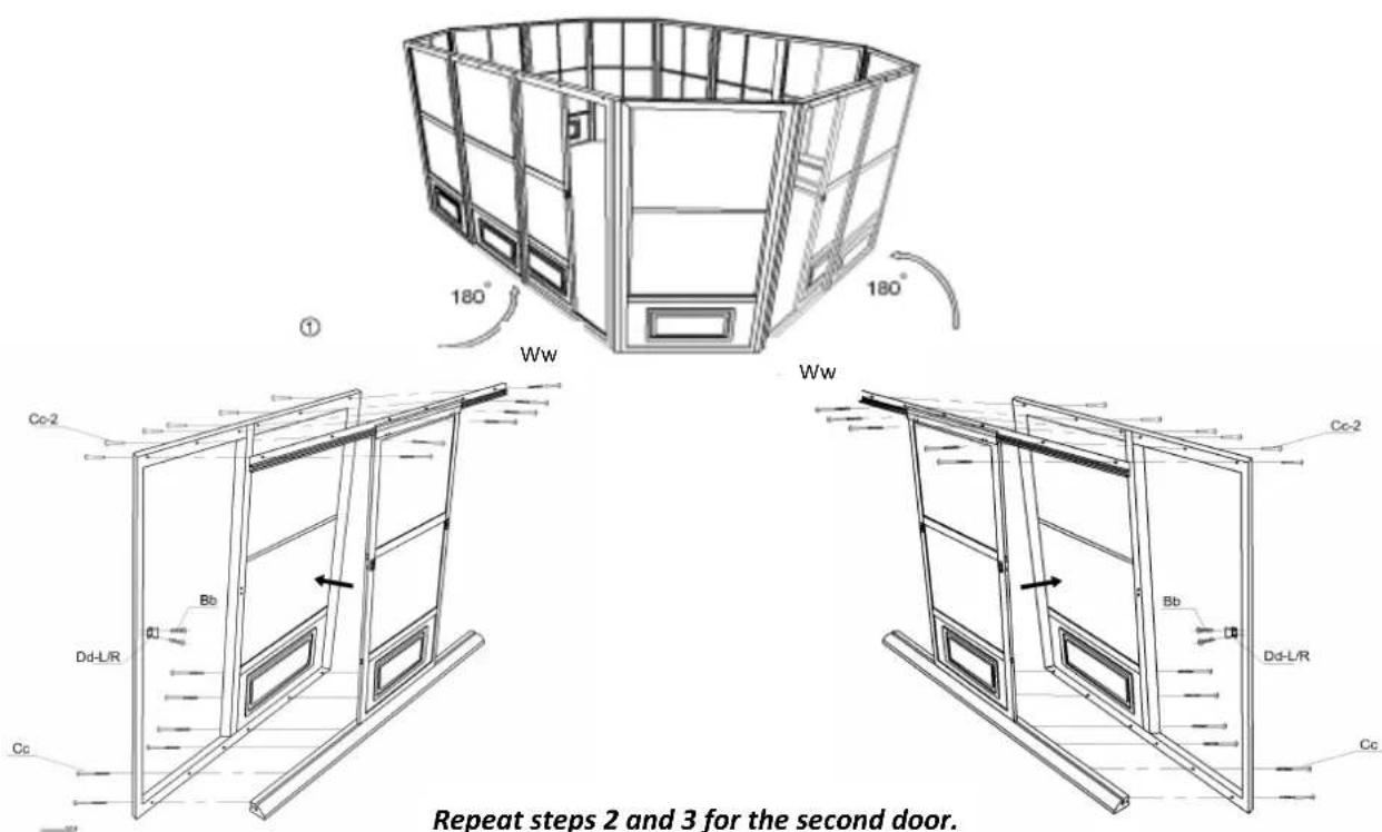
Step 4:
- Aach roof raers (L) to the central hub (N) using bolt (Bb).
- Use screw (Z) to ax the raers (L) onto the top of panels going through the metal piece aached to the raer (L).
Note: Raers must be axed where panels connect to each other.

Step 5:
Use the same method to assemble roof raers (K) for the angled panels. The raers (K) should be axed to the moung bracket using the hole that will be furthest away from the corner of the unit.
Note: Do not ghten the bolts right away as you may have to adjust the angle when inserng the PC roof panels.

Step 6:
Use nut (Hh) and washer (Gg) to ax the top cap (M) to the central hub (N).

Step 7:
First remove the protecve layer from the PC roof panels, then insert them (Y, Aa, LI, Qq) into the roof raers according to the below drawing instrucons.
Note: the side that had the protecve layer should be face down.
![graph TD A["Qq"] --> B["L"] A --> C["K"] B --> D["Aa"] B --> E["Y"] C --> F["Aa"] C --> G["Y"] D --> H["LI"] E --> I["LI"] F --> J["LI"] G --> K["LI"] H --> L["Qg"] I --> M["Qg"] J --> N["Qg"] K --> O["Qg"] style A fill:#f9f,stroke:#333 style B fill:#ccf,stroke:#333 style C fill:#ccf,stroke:#333 sty…](/content/2026/05/1094673/images/68b228dd22866b1afcc10bbcb6b8badc7b582caf989f0456d77f6f5853a60ee7.jpg)
Step 8:
Aer inserng the upper PC panels, insert the aluminum middle roof joints (O, P, Q, Pp) into the roof raers. The below drawing view is from inside the solarium looking up.
Note:
• The drain holes on the aluminum middle roof joints (O, P, Q, Pp) should be at the bottom.
- To adjust the middle joints to line up: once all polycarbonate roof panels are in place, use a small piece of wood and hammer, then tap down on the middle of the joint bringing it down and holding at the same me the joint and top polycarbonate.
Do not tap too hard.

Step 9:
Aer the installaon on the middle roof joints complete, insert the boom PC roof panels (Jj, Kk, Mm, Rr) according to below drawing. They should overlap about two inches under the upper PC roof panels and into the aluminum middle roof joints.
![graph TD A["Before"] --> B["Aer"] B --> C["Central System"] C --> D["Rr"] C --> E["Kk"] C --> F["Jj"] C --> G["Mm"] C --> H["Mm"] C --> I["Kk"] C --> J["Jj"] C --> K["Mm"] style A fill:#f9f,stroke:#333 style B fill:#f9f,stroke:#333 style C fill:#ccf,stroke:#333 style D fill:#cfc,stroke:#333 style E…](/content/2026/05/1094673/images/cb31c5348fe6b21703cb3f725f9f58003b5496c558f26287e9c86b68c59ff425.jpg)
Step 10:
Once the PC roof is complete, use aluminum edging (S, U, W, Ss) to surround the edges of PC roof, and using bolt (Bb) and roof joint (R), ghten securely.

Step 11:
Once the installation of the edging complete, start axing the roof cross bars (T, V, X, Tt) using bolt (Ff). Ax the top cross bars (Uu) onto the roof raer (L) using bolt (Ff).

Step 12:
Inside each of the panels (A, B), push two plastic plugs (II) into the ground, and then screw down the panels using two screws (Ee) for each panels.

Special notes:
- To remove windows (08-219), pull 1 pin out of the lock posion and push the frame to the end of the track, then ease the window out of the tracks one side at a me.
- To remove screening panel, rst remove windows, then unscrew the 2 screws at the top corners of the screen frame.
- Note that this unit is not waterproof. For best protecon against rain, close the windows of each frame with the outside window in the center, and the inside window at the top.

*Suggestions
The below mentioned are only suggestions in order to permit drainage, these will vary depending on your flooring – material, flatness and slope.
FOR CONCRETE FLOORING

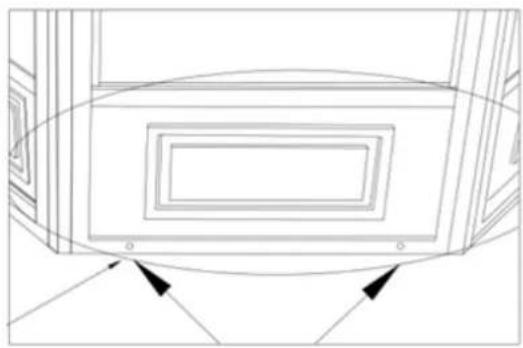
On the outside face, it is suggested to drill holes at the bottom end of the panels to permit drainage when installing on Concrete floor
For Wooden Deck
Drill through the wooden deck where drain holes are located to permit drainage

WHEN LOOKING
FROM THE INSIDE
WOODEN DECK
12X15 Solarium SAND (see page 17 for SLATE parts)
| DESCRIPTION | PACKED IN BOX | QTY | DRAWING | DESCRIPTION | PACKED IN BOX | QTY | DRAWING |
| 08-129-12 REGULAR FRAME A | 2 | 5 |  | 08-130-12 FRAME NEXT TO DOOR B (with extra holes) | 2 | 1 | 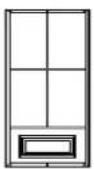 |
| 3 | 5 | 3 | 1 | ||||
| 08-131-12 SLIDING DOOR C | 2 | 1 |  | 08-132-12 SLIDING DOOR FRAME D | 2 | 1 | 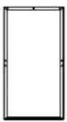 |
| 3 | 1 | 3 | 1 | ||||
| 08-133-12 CONNECTING PIECE E Length 200.6 cm | 4 | 12 |  | 08-136-12 TOP DOOR RAIL F Length 206 cm | 4 | 2 | 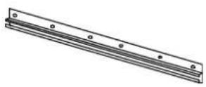 |
| 08-137-12 BOTTOM DOOR RAIL G Length 206 cm | 4 | 2 | 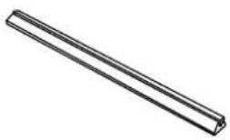 | 08-138-12 PLASTIC STOPPER H | 5 | 4 |  |
| 08-139-12 135° ANGLED OUTSIDE CONNECTOR I Length 200.6 cm | 4 | 8 |  | 08-140-12 135° ANGLED INSIDE CONNECTOR J Length 200.6 cm | 4 | 8 | 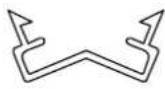 |
| 08-141-12 ROOF RAFTER K Length 239.7 cm | 4 | 8 |  | 08-142-12 ROOF RAFTER L Length 211 cm | 4 | 6 |  |
| 08-179-12 TOP CAP M | 5 | 1 |  | 08-178-12 CENTRAL HUB N | 5 | 1 |  |
| 08-145 MIDDLE ROOF JOINT O | 5 | 4 | 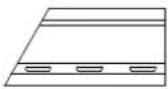 | 08-146 MIDDLE ROOF JOINT P | 5 | 4 |  |
| 08-147-12MIDDLEROOF JOINTQ | 5 | 4 | 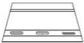 | 08-148-12ROOFRAFTER CAPR | 5 | 14 | 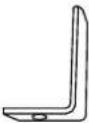 |
| 08-149-12EDGINGSLength 120.6 cm | 5 | 4 |  | 08-150-12ROOF CROSSBARTLength 94.4 cm | 5 | 4 |  |
| 08-151-12EDGINGULength 120.6 cm | 5 | 4 |  | 08-152-12ROOF CROSSBARVLength 94.4 cm | 5 | 4 |  |
| 08-153-12EDGINGWLength 120.6 cm | 5 | 4 |  | 08-154-12ROOF CROSSBARXLength 94.4cm | 5 | 4 |  |
| 08-155(24 1⁄4"x42 1⁄4")TOP ROOFLeft PANELY | 1 | 4 |  | 08-156-12SCREWZ | 5 | 28 | 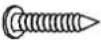 (M4*16mm) (M4*16mm) |
| 08-157(24 1⁄2"x46 1⁄2")TOP ROOFCORNERPANELAa | 1 | 4 |  | 08-158-12BOLTBb | 5 | 54 |  (M6*16mm) (M6*16mm) |
| 08-161-12BOLTCc | 5 | 12 |  (M6*70mm) (M6*70mm) | 08-165-12RIGHT DOORLATCHDd-R | 5 | 2 |  |
| 08-169-12LEFT DOORLATCHDd-L | 5 | 2 | 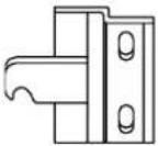 | 08-167-12SCREWEe | 5 | 24 |  (M6x63.5mm) (M6x63.5mm) |
| 08-168-12BOLTFf | 5 | 18 | (M6*12mm) | 08-187-12WASHERGg | 5 | 39 | |
| 08-189-12ACORN NUTHh | 5 | 3 | 08-193-12PLASTIC PLUGli | 5 | 24 | ||
| 08-195(47"x47 1⁄2")BOTTOM ROOFCORNER PANELJj | 1 | 4 | 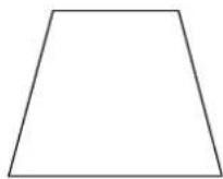 | 08-196(46 1⁄4"x43")BOTTOMROOF LEFTPANELKk | 1 | 4 |  |
| 08-197(24 1⁄4"x42 1⁄2")TOP RIGHTROOF PANELLI | 1 | 4 | 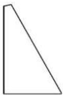 | 08-198(46 1⁄4"x43")BOTTOMROOF RIGHTPANELMm | 1 | 4 |  |
| 08-134-12UPPER DOORRAIL END CAPNn | 5 | 4 |  | 08-135-12SCREWOo | 5 | 4 |   |
| 08-170MIDDLE ROOFJOINTPp | 5 | 2 | 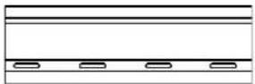 | 08-172(41 1⁄4"x42 1⁄4")TOP ROOFCENTERPANELQq | 1 | 2 |  |
| 08-171(41 1⁄4"x43")BOTTOM ROOFCENTER PANELRr | 1 | 2 |  | 08-173EDGINGSs | 5 | 2 |  |
| 08-174ROOF CROSSBARTt | 5 | 2 |  | 08-175TOP ROOFCROSS BARUu | 5 | 2 |  |
| 12-037FEMALE BOLTCc-2 | 5 | 12 |  M6*60mm M6*60mm | 12-047BOLTWw | 5 | 12 |  M5*15mm M5*15mm |
| AVAILABLE REPLACEMENT PARTS | |||
| DESCRIPTION | DRAWING | DESCRIPTION | DRAWING |
| 08-219-12PVC WINDOW(in frame) |  | 11-572-12BOTTOMPLASTIC PANEL(for wall panels) | 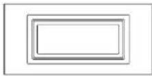 |
| 10-493PVC WINDOW(replacementmaterial only) |  | 11-823-12BOTTOMPLASTIC PANEL(for double doors) |  |
| 85-417-PROUND SPLINEFOR PVCWINDOW |  | 15-097-12DOOR WHEELASSEMBLY |  |
| 15-123-12PIN FOR PVCWINDOW | 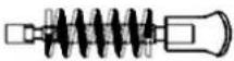 | 11-736-12RECEIVERCHANNEL FORDOUBLE DOOR | |
| 13-054PC WINDOW(for double door) | 10-458REPLACEMENTWEATHERSTRIP |  | |
| 12-046-12MOSQUITOSCREEN (inframe) | 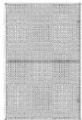 | 15-124-12MOUNTINGBRACKET FORRAFTER (K) | 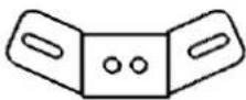 |
| 85-014REPLACEMENTSCREENING(no frame) |  | 15-125-12MOUNTINGBRACKET FORRAFTER (L) |  |
| 85-417-SROUND SPLINEFORSCREENING |  | 19-102-12MOUNTINGBRACKET FORRAFTER (Xx) |  |
| DESCRIPTION | COLOUR | PART # | |
| SPRAY PAINT | SAND | 11-699 | |
| PAINT PEN | 18-245 | ||
12X15 Solarium SLATE
| DESCRIPTION | PACKED IN BOX | QTY | DRAWING | DESCRIPTION | PACKED IN BOX | QTY | DRAWING |
| 08-129-32 REGULAR FRAME A | 2 | 5 |  | 08-130-32 FRAME NEXT TO DOOR B (with extra holes) | 2 | 1 | 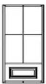 |
| 3 | 5 | 3 | 1 | ||||
| 08-131-32 SLIDING DOOR C | 2 | 1 |  | 08-132-32 SLIDING DOOR FRAME D | 2 | 1 | 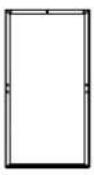 |
| 3 | 1 | 3 | 1 | ||||
| 08-133-32 CONNECTING PIECE E Length 200.6 cm | 4 | 12 |  | 08-136-32 TOP DOOR RAIL F Length 206 cm | 4 | 2 |  |
| 08-137-32 BOTTOM DOOR RAIL G Length 206 cm | 4 | 2 |  | 08-138-32 PLASTIC STOPPER H | 5 | 4 |  |
| 08-139-32 135° ANGLED OUTSIDE CONNECTOR I Length 200.6 cm | 4 | 8 |  | 08-140-32 135° ANGLED INSIDE CONNECTOR J Length 200.6 cm | 4 | 8 |  |
| 08-141-32 ROOF RAFTER K Length 239.7 cm | 4 | 8 |  | 08-142-32 ROOF RAFTER L Length 211 cm | 4 | 6 |  |
| 08-179-32 TOP CAP M | 5 | 1 |  | 08-178-32 CENTRAL HUB N | 5 | 1 |  |
| 08-145 MIDDLE ROOF JOINT O | 5 | 4 | 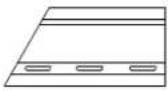 | 08-146 MIDDLE ROOF JOINT P | 5 | 4 |  |
| 08-147-32MIDDLEROOF JOINTQ | 5 | 4 |  | 08-148-32ROOFRAFTER CAPR | 5 | 14 |  |
| 08-149-32EDGINGSLength 120.6 cm | 5 | 4 |  | 08-150-32ROOF CROSSBARTLength 94.4 cm | 5 | 4 |  |
| 08-151-32EDGINGULength 120.6 cm | 5 | 4 |  | 08-152-32ROOF CROSSBARVLength 94.4 cm | 5 | 4 |  |
| 08-153-32EDGINGWLength 120.6 cm | 5 | 4 |  | 08-154-32ROOF CROSSBARXLength 94.4cm | 5 | 4 |  |
| 08-155(24 1⁄4"X42 1⁄4")TOP ROOFLEFT PANELY | 1 | 4 |  | 08-156-32SCREWZ | 5 | 28 |  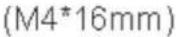 |
| 08-157(24 1⁄2"x46 1⁄2")TOP ROOFCORNERPANELAa | 1 | 4 |  | 08-158-32BOLTBb | 5 | 54 |  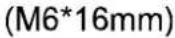 |
| 08-161-32BOLTCc | 5 | 12 |  (M6*70mm) (M6*70mm) | 08-165-32RIGHT DOORLATCHDd-R | 5 | 2 | 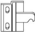 |
| 08-169-32LEFT DOORLATCHDd-L | 5 | 2 |  | 08-167-32SCREWEe | 5 | 24 |  (M6x63.5mm) (M6x63.5mm) |
| 08-168-32 BOLT Ff | 5 | 18 | 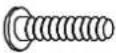 (M6*12mm) (M6*12mm) | 08-187-32 WASHER Gg | 5 | 39 | [2035] |
| 08-189-32 ACORN NUT Hh | 5 | 3 | [M2V] | 08-193-32 PLASTIC PLUG li | 5 | 24 | [2048] |
| 08-195 (47"x47 1⁄2") BOTTOM ROOF CORNER PANEL Jj | 1 | 4 |  | 08-196 (46 1⁄4"x43") BOTTOM ROOF LEFT PANEL Kk | 1 | 4 |  |
| 08-197 (24 1⁄4"x42 1⁄2") TOP RIGHT ROOF PANEL LI | 1 | 4 | 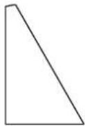 | 08-198 (46 1⁄4"x43") BOTTOM ROOF RIGHT PANEL Mm | 1 | 4 |  |
| 08-134-32 UPPER DOOR RAIL END CAP Nn | 5 | 4 |  | 08-135-32 SCREW Oo | 5 | 4 |  |
| 08-170 MIDDLE ROOF JOINT Pp | 5 | 2 |  | 08-172 (41 1⁄4"x42 1⁄4") TOP ROOF CENTER PANEL Qq | 1 | 2 |  |
| 08-171 (41 1⁄4"x43") BOTTOM ROOF CENTER PANEL Rr | 1 | 2 |  | 08-173 EDGING Ss | 5 | 2 |  |
| 08-174 ROOF CROSS BAR Tt | 5 | 2 |  | 08-175 TOP ROOF CROSS BAR Uu | 5 | 2 |  |
| 12-037 FEMALE BOLT Cc-2 | 5 | 12 |  M6*60mm M6*60mm | 12-047 BOLT Ww | 5 | 12 | 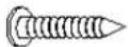 M5*15mm M5*15mm |
| AVAILABLE REPLACEMENT PARTS | ||||
| DESCRIPTION | DRAWING | DESCRIPTION | DRAWING | |
| 08-219-32PVC WINDOW(in frame) |  | 11-572-32BOTTOMPLASTIC PANEL(for wall panels) | 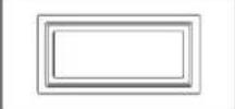 | |
| 10-493PVC WINDOW(replacementmaterial only) |  | 11-823-32BOTTOMPLASTIC PANEL(for double doors) | 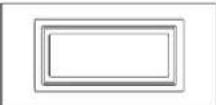 | |
| 85-417-PROUND SPLINEFOR PVCWINDOW |  | 15-097-32DOOR WHEELASSEMBLY | 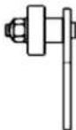 | |
| 15-123-32PIN FOR PVCWINDOW |  | 11-736-32RECEIVERCHANNEL FORDOUBLE DOOR | ||
| 13-054PC WINDOW(for double door) |  | 10-458REPLACEMENTWEATHERSTRIP |  | |
| 12-046-32MOSQUITOSCREEN (inframe) |  | 15-124-32MOUNTINGBRACKET FORRAFTER (K) | 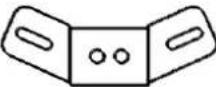 | |
| 85-014REPLACEMENTSCREENING(no frame) |  | 15-125-32MOUNTINGBRACKET FORRAFTER (L) | 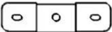 | |
| 85-417-SROUND SPLINEFORSCREENING |  | 19-102-32MOUNTINGBRACKET FORRAFTER (Xx) |  | |
| DESCRIPTION | COLOUR | PART # | ||
| SPRAY PAINT | SLATE | 18-125 | ||
| PAINT PEN | 18-126 | |||
Note: The dimensions are approximate.

41215 SOLARIUM
AU REBOARD DU TOIT
ROOF OVERHANG
- GAZEBO PENGUIN INC
- DO NOT DESTROY THE BOXES UNTIL COMPLETELY ASSEMBLED PLEASE VERIFY THE CONTENT OF EACH BOX AGAINST THE LIST OF PARTS
- WARNING
- PRIOR TO ASSEMBLY
- ANCHORING INSTRUCTIONS
- CARE AND MAINTENANCE
- ROOF PANELS
- STRUCTURE
- MAINTENANCE NOTES
- ONE YEAR LIMITED WARRANTY
- CONDITIONS FOR EXERCISING THE WARRANTY
- LIMITATIONS ON THE WARRANTY
- BEFORE YOU ASSEMBLE THE SOLARIUM
- PLEASE DON'T DESTROY THE BOXES UNTIL COMPLETELY ASSEMBLED
- TOOLS NEEDED
- 12X15 SOLARIUM ASSEMBLY INSTRUCONS
- STEP 1
- STEP 2
- STEP 3: PLEASE NOTE THE SLIDING DOOR SHOULD BE INSTALLED FROM THE INSIDE OF THE SOLARIUM
- STEP 4
- STEP 5
- STEP 6
- STEP 7
- STEP 8
- NOTE
- STEP 9
- STEP 10
- STEP 11
- STEP 12
- SPECIAL NOTES
- SUGGESTIONS
- FOR WOODEN DECK
Brand : Gazebo Penguin
Model : 41215-12
Category : Tent