
DSH-HWK - Dash cam Dashmate - Free user manual and instructions
Find the device manual for free DSH-HWK Dashmate in PDF.

| Product Type | Hardwire Kit for Dashcams |
| Compatibility | Universal for dashcams with Mini USB or Micro USB input; works with 12V and 24V vehicles |
| Input Voltage | 10V - 32V DC |
| Output Voltage | 5V DC (5.2V no load, 5.1V at 0.5A, 5V at 1A) |
| Output Current | 2A max |
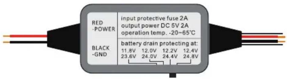
| Battery Drain Protection | Selectable voltage cut-off bands: 11.8V / 12.0V / 12.2V / 12.4V (12V system) or 23.6V / 24.0V / 24.4V / 24.8V (24V system) |
| Additional Protections | Reverse polarity, short circuit, over-temperature, over-voltage, over-load |
| Input Cable Length | 1 meter (twin red/black wires, 22 AWG) |
| Output Cable Length | 3 meters (twin wires, 22 AWG) |
| Output Connector | DC 3.5x1.35 mm female |
| Dashcam USB Connectors Included | Mini USB and Micro USB adaptor cables (400 mm each) |
| Fuse Tap Cables Included | ATS (Standard), Mini, Micro2, Micro – all with 5A fuse, 125 mm length |
| Control Box Material | Flame retardant ABS (94V0), contains DC-DC converter |
| Working Temperature | -20°C to 65°C |
| Installation Difficulty | Recommended professional installation; DIY possible with vehicle manual |
| Warranty | 12 months from date of purchase (conditions apply) |
| Included Accessories | Cable ties (4 pcs), adhesive pad for control box |
Frequently Asked Questions - DSH-HWK Dashmate
User questions about DSH-HWK Dashmate
0 question about this device. Answer the ones you know or ask your own.
Ask a new question about this device
Download the instructions for your Dash cam in PDF format for free! Find your manual DSH-HWK - Dashmate and take your electronic device back in hand. On this page are published all the documents necessary for the use of your device. DSH-HWK by Dashmate.
USER MANUAL DSH-HWK Dashmate
Constant power for your dashcam.

natural_image
Close-up of a dashmate technology driver module connected to a camera lens via cable (no text or symbols visible)
Universal Kit

Car & Truck
Compatible

Constant Power

Battery Drain Protection
DSH-HWK | USER MANUAL
TABLE OF CONTENTS
NOTES AND INSTALLATION ....4
1 PRODUCT INFORMATION......5
1.1 INTRODUCTION ....5
1.2 FEATURES....5
1.3 PACKAGE CONTENTS....6-7
2 BATTERY DRAIN PROTECTION....7
2.1 SETTING THE CUT OFF VOLTAGE 7
2.2 VEHICLE BATTERY LEAD ACID STATES AND CAPACITY....8
3 INSTALLATION....9
3.1 CONNECTING HARDWIRE KIT TO YOUR DASHCAM....10
3.1.1 ATTACHING THE USB CONNECTOR TO THE DASHCAM.....10
3.2 ROUTING THE OUTPUT CABLE
FROM THE DASHCAM TO THE FUSE BOX 10-11
3.2.1 INSTALLING THE OUTPUT CABLES IN VEHICLE....11-14
3.2.2 HOUSING THE OUTPUT CABLE 14-15
3.3.1 CONNECTING TO THE FUSE BOX....16-17
3.3.2 CONNECTING TO GROUND....18
4 SPECIFICATIONS 19
5 WARRANTY TERMS & CONDITIONS 20
6 NOTES 21-22
NOTES AND INSTALLATION
IMPORTANT: REFER TO YOUR VEHICLE OWNER'S MANUAL TO DETERMINE:
- Location of the fuse box
• How to access the fuse box
• The type of fuse tap required
It is highly recommended that you have a quick read of the installation instructions in this user guide. If you are not comfortable with the process please seek further assistance from an authorised technician.
Since power to your dashcam will be running via a power cable from the fuse box you will need to determine your vehicle's fuse box location. Most vehicles have a fuse box underneath the dashboard on the driver's side which is easily accessible below the steering column (behind a removable panel). However the location does vary between vehicle make and model.
There are 4 types of fuse tap cables included in this kit. Check to see if these fuses suit your vehicle's fuse box. If none are suitable you will need to purchase the correct fuse to attach the hardwire kit to your vehicle's power source.
Note: You may need to consult your vehicle manufacturer for instructions on how to remove vehicle fittings (example A pillar cover) for routing the hardwire kit cables inside your vehicle and for where airbags are located so that these are not obstructed in case of deployment by routed cables.
Installation of DSH-HWK is recommended to be performed by a technician. Working with your vehicle's power system can be dangerous to both you and your vehicle if you do not know what you are doing. If you have any doubts please consult a professional. Dashmate recommends professional installation only of this dashcam hardwire kit.
IMPORTANT: Refer to your dashcam owner's manual for initial installation of your dashcam in your vehicle.
DSH-HWK is a kit that allows for the provision of constant power from your vehicle battery to your dashcam. Any issues with your dashcam should be referred to your dashcam's manufacturer.
1 PRODUCT INFORMATION
Get constant power for your dashcam. DSH-HWK connects to your vehicle battery through your vehicle's fuse box and provides constant power to your dashcam when the engine is turned off. It includes several fuse tap options that suit most vehicles* and your dashcam connects to the hardwire kit with either the Micro USB or Mini USB connectors included. For latest manual and product updates please visit our website.
*A suitable fuse tap cable will need to be purchased separately if the fuse tap cable options included in this pack are not suitable for your vehicle's fuse box.
1.1 INTRODUCTION
Thank you for purchasing a DSH-HWK Hardwire Kit. DSH-HWK is a simple plug and play solution to hardwire your Dashmate dashcam or any other dashcam with a Mini USB and Micro USB connection. Please read through these instructions carefully before attempting to install or use this product.
1.2 FEATURES
- Universal kit suits Dashmate and all other dashcams with Mini USB or Micro USB connections.
- Can be installed in cars and trucks as is compatible with 12V and 24V batteries.
- Provides constant power to your dashcam when your vehicle is turned off.
- Is protected with Battery Drain Protection to safeguard your dashcam from draining your vehicle's battery. Your battery will stop providing power to your dashcam if your battery level gets too low.
- Includes 4 different fuse tap cables – simply plug the required fuse tap cable into the vehicle's fuse box to provide your dashcam with its own power supply without engaging the cigarette socket.
- Includes both Mini USB and Micro USB connectors for connection to all Dashmate dashcam models
1.3 PACKAGE CONTENTS
HARDWIRE KIT

- Red Input Connector
- Black Input Connector
- Input Cable
- Control Box with Adhesive Pad
- Output Cable
- Output Connector
VEHICLE FUSE OPTIONS (USE ONLY ONE OPTION FOR INSTALLATION)


- ATS (Standard) Fuse Cable
- Mini Fuse Cable
- Micro2 Fuse Cable
- Micro Fuse Cabler
DASHCAM OUTPUT CONNECTOR OPTIONS (USE ONLY ONE OPTION FOR INSTALLATION)


- Mini USB Cable
- Micro USB Cable
1.3 PACKAGE CONTENTS CONT'D
ACCESSORIES

natural_image
Close-up of black cable clips with a loop, no text or symbols visible- Cable Ties x 4
2 BATTERY DRAIN PROTECTION
The Hardwire Kit will protect your dashcam from draining your vehicle's battery. If your vehicle's battery voltage gets too low, DSH-HWK will stop powering your camera to save power. You will never have to worry about your car's battery dying when DSH-HWK is in use.
2.1 SETTING THE CUT OFF VOLTAGE
Set the cut off voltage according the temperature and the capacity you'd like to consume before the hardwire kit cuts off the output.
There are 4 protecting bands set in the hardwire kit, you can switch according your requirement.
For 12V Batteries
The protecting voltages are 11.8V / 12.0V / 12.2V / 12.4V.
12.2V recommended for most users in general driving conditions.
For 24V Batteries
The protecting voltages are 23.6V / 24.0V / 24.4V / 24.8V.
24.4V recommended for most users in general driving conditions.
The hardwire kit will identify the lead acid battery type automatically (12V or 24V) and protect your battery from draining accordingly.
2.2 VEHICLE BATTERY LEAD ACID STATES AND CAPACITY
Use the below table to assist in determining your desired voltage cut off level for battery drain protection.
For example if the temperature is 38^ C and you want to keep a 75% lead acid state capacity remaining in your battery when the hardwire kit cuts off output (meaning the battery voltage is approximately 12.402V) the cut off voltage should be set at the 12.4V band. This means there will be 25% capacity in your vehicle battery which will be used for your dashcam while your vehicle is parked.
Using a 50Wh lead acid battery for an example, the 25% consumption will support approximately 50 hours of dashcam use.
| Temperature Lead Acid State & Voltage (Volt) | |||||
| °C 100% | 75% 50% 2 | 5% 0 | |||
| -7 12.794 | 12.594 12.38 | 4 12.204 12.034 | |||
| -1 12.77 12 | 57 12.36 12.18 | 12.01 | |||
| 4 | 12.746 | 12.546 | 12.336 | 12.156 | 11.986 |
| 10 | 12.722 | 12.522 | 12.312 | 12.132 | 11.962 |
| 16 | 12.698 12 | 498 12.288 | 12.108 | 11.938 | |
| 21 12.674 | 12.474 | 12.264 12.084 | 11.914 | ||
| 27 | 12.65 | 12.45 | 12.24 | 12.06 | 11.89 |
| 32 | 12.626 12 | 462 12.216 | 12.036 | 11.866 | |
| 38 | 12.602 12 | 406 12.192 | 12.012 | 11.842 | |
| 43 | 12.578 | 12.378 | 12.168 | 11.988 | 11.818 |
| 49 | 12.554 | 12.354 | 12.144 | 11.964 | 11.794 |
NOTE: Please be advised that the above table is to be used as a reference guide only in order to determine an appropriate voltage selection dependent on the battery age and condition.
3INSTALLATION
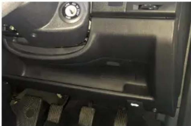
The location of the vehicle's fuse box varies from vehicle make and model. Locations may include underneath the driver's side dashboard, behind the glove box and underneath the central console. Where in doubt, always refer to your vehicle owner's manual to determine the location of the fuse box in your vehicle.
NOTE: The images in this installation were taken for a vehicle where the fuse box is located under the driver's side dashboard (Fig. 1, 2) and should be used as a guide only for a DIY installation. To ensure proper installation Dashmate recommends DSH-HWK be installed by a professional technician.
natural_image
Close-up of a car interior showing dashboard, steering wheel, and gear (no visible text or symbols)FIG. 1

natural_image
Interior view of a car dashboard with visible wiring and components (no text or symbols)FIG. 2
There are 2 main stages in the hardwire kit installation
- Connecting output cable to your dashcam
- Connecting input cables to your fuse box and grounding
NOTE: Determine the location of your vehicle's fuse box before commencing the installation of the hardwire kit. Where in doubt, refer to the vehicle owner's manual.
3.1 CONNECTING HARDWIRE KIT TO YOUR DASHCAM
IMPORTANT: Refer to your dashcam owner's manual for initial installation of your dashcam in your vehicle.
3.1.1 ATTACHING THE USB CONNECTOR TO THE DASHCAM
-
Two dashcam connector cables are included with DSH-HWK – one with a Mini USB plug and one with a Micro USB plug. Determine the connection interface type on your dashcam and then select the appropriate USB connector cable. (Fig 3)
-
Insert the USB connector cable to your dashcam (Fig 4)

natural_image
Close-up of hands holding a black digital camera module with a small connector, no visible text or symbolsFIG. 3

natural_image
Close-up of hands holding a black remote camera with a cable inserted, showing no visible text or symbols.FIG. 4
3.2 ROUTING THE OUTPUT CABLE FROM THE DASHCAM TO THE FUSE BOX
NOTE: You may need to consult your vehicle manufacturer for instructions on how to remove vehicle fittings (example A pillar cover) for routing the hardwire kit cables inside your vehicle and for where airbags are located so that these are not obstructed in case of deployment by routed cables.
3.2 ROUTING THE OUTPUT CABLE FROM THE DASHCAM TO THE FUSE BOX CONT'D
3.2.1 INSTALLING THE OUTPUT CABLES IN VEHICLE
- Once the USB connector cable is attached to your dashcam, it then needs to be connected to the hardwire kit's output cable. (Fig 5)
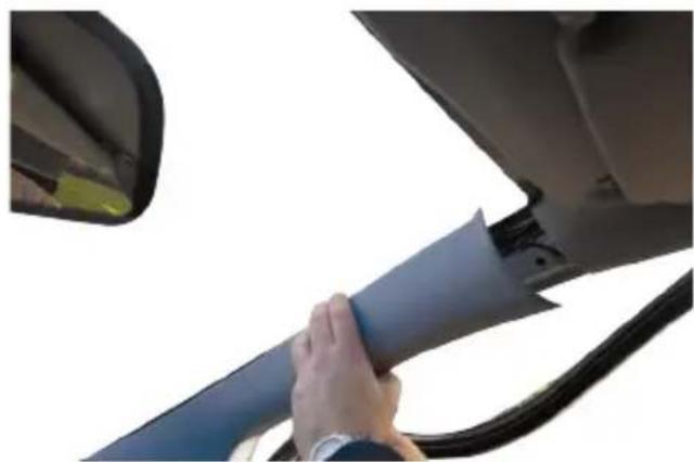
- The hardwire kit output cable will then need to be recessed into the roof lining where it meets the edge of the windscreen to conceal the cable (Fig 6a, 6b)
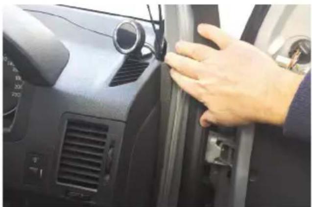
- At the farthest end of the roof lining the output cable needs to then be routed along the A pillar that is closest to the fuse box of the vehicle. You will need to remove the door seal (Fig 7) and A pillar cover (Fig 8) to route the cable (Fig 9a, 9b). Route the cable all the way down to the end of the A pillar where it meets the dashboard.
- Use the provided cable ties to attach the output cable to any existing cable(s) that may be housed in the A pillar (Fig 10a, 10b).
NOTE: The A pillar used to route the cable is not always the driver's side one as shown. Refer to the vehicle owner's manual to determine location of fuse box in your vehicle. The output cable needs to be routed in the A-pillar closest to the fuse box.

natural_image
Close-up of hands holding a small object near a car's front panel with a mounted sensor device above (no visible text or symbols)FIG. 5

natural_image
Close-up of hands adjusting a car's rearview mirror and camera module (no visible text or symbols)FIG. 6a
3.2 ROUTING THE OUTPUT CABLE FROM THE DASHCAM TO THE FUSE BOX CONT'D
3.2.1 INSTALLING THE OUTPUT CABLES IN VEHICLE CONT'D

natural_image
Interior view of a car showing a mounted sensor and rear-mounted device (no visible text or symbols)FIG. 6b

natural_image
Close-up of a person's hand gripping a car trunk, no visible text or symbolsFIG. 7
natural_image
Close-up of a hand adjusting a blue car seat cover, with a partial view of the door and window visible (no text or symbols)FIG. 8
3.2 ROUTING THE OUTPUT CABLE FROM THE DASHCAM TO THE FUSE BOX CONT'D
3.2.1 INSTALLING THE OUTPUT CABLES IN VEHICLE CONT'D

natural_image
Close-up of a hand inserting cable into a car's side panel (no text or symbols visible)FIG. 9a

natural_image
Close-up of hands installing or adjusting a car door panel on the steering wheel (no visible text or symbols)FIG. 9b

natural_image
Close-up of hands installing or adjusting a black plastic component (no visible text or symbols)FIG. 10a
3.2 ROUTING THE OUTPUT CABLE FROM THE DASHCAM TO THE FUSE BOX CONT'D
3.2.1 INSTALLING THE OUTPUT CABLES IN VEHICLE CONT'D

natural_image
Close-up of hands installing or adjusting a black metal panel with wires and small holes (no visible text or symbols)FIG. 10b
3.2.2 HOUSING THE OUTPUT CABLE
- Where the output cable from the A pillar meets the side of the dashboard, the output cable will then need to be routed towards the direction of the fuse box by concealing the cable along the side of the vehicle dash (Fig 11a, 11b).
- Any excess output cable length can be wrapped and held together with a cable tie when it reaches the fuse box (Fig 12)
- Tuck away any excess output cable behind the fuse box (Fig 13)
- If required, peel off the control box label to attach the control box to the vehicle (near the fuse box) with the adhesive tape.

natural_image
Close-up of a car's front panel showing a hand adjusting the grille and vent, with no visible text or symbols.FIG. 11a
3.2 ROUTING THE OUTPUT CABLE FROM THE DASHCAM TO THE FUSE BOX CONT'D
3.2.2 HOUSING THE OUTPUT CABLE
natural_image
Close-up of a hand adjusting a car's front panel with a sensor and ventilation grille (no visible text or symbols)FIG. 11b

natural_image
Hand holding a small electronic component with wires and wiring inside a vehicle (no visible text or symbols)FIG. 12

natural_image
Close-up of a car interior showing wiring and components, no visible text or symbolsFIG. 13
3.2 CONNECTING HARDWIRE KIT TO YOUR FUSE BOX AND GROUNDING
3.3.1 CONNECTING TO THE FUSE BOX
NOTE: Refer to your vehicle's fuse layout panel to determine the permanent power fuse for constant power feed. The fuse cable needs to be connected to the 12V/24V battery feed.
- Determine the fuse tap cable required for connection to your fuse box. Where in doubt refer to the vehicle owner's manual.
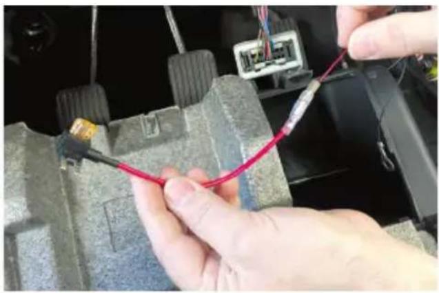
- Place the vehicle fuse in the fuse tap cable. Note the correct position location for both the vehicle fuse and the hardwire kit fuse in the fuse tap cable (Fig 14).
- Locate the input cable and connect the fuse tap cable to the red input connector (Fig 15a, 15b). Ensure connection is secure.
- Insert the fuse tap into the fuse box (Fig 16a, 16b).
- Tuck away any excess red input cable behind the fuse box.
NOTE: To determine constant power feed fuse use a voltage meter.


natural_image
Close-up of hands using a tool to wire a red cable on a mechanical component (no text or symbols visible)FIG. 15a
3.2 CONNECTING HARDWIRE KIT TO YOUR FUSE BOX AND GROUNDING CONT'D
3.3.1 CONNECTING TO THE FUSE BOX CONT'D
natural_image
Close-up of hands connecting a red cable to a car's electrical connector (no visible text or symbols)FIG. 15b

natural_image
Close-up of hands installing or adjusting a car electrical panel with red and blue wires (no visible text or symbols)FIG. 16a

natural_image
Close-up of hands holding a red cable with multiple red and blue connectors on an electrical panel (no visible text or symbols)FIG. 16b
3.2 CONNECTING HARDWIRE KIT TO YOUR FUSE BOX AND GROUNDING CONT'D
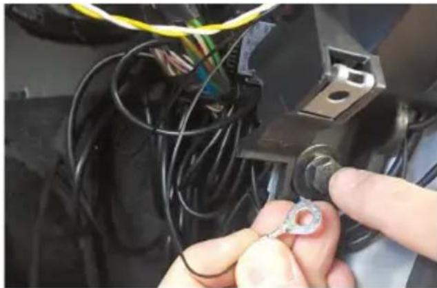
3.3.2 CONNECTING TO GROUND
-
Locate earth terminal/bolt or any vehicle bolt accessible that is mounted to the chassis of the vehicle or any metal part of the vehicle - located near the vehicle fuse box (Fig (17).
-
Feed black input wire eyelet into bolt and screw bolt back on existing location.
-
Tuck away any excess input cable behind the fuse box.
NOTE: The black earth cable needs to be connected to the vehicle chassis otherwise it will not earth out.
natural_image
Close-up of hands installing a small electrical component with wires and a terminal block (no visible text or symbols)FIG. 17
4SPECIFICATIONS
| HARDWIRE KIT: CABLES | |
| RED INPUT CONNECTOR BULLET | T PLUG OD4MM |
| BLACK INPUT CONNECTOR ROUND | UND RING TERMINAL, NICKEL PLATED, OD10MM ID6MM L20MM |
| INPUT CABLE TWIN CABLES (RED: 12V/24V POWER; BLACK: GROUND), 2X22AWG, CONDUCTOR, SR-PVC INSULATION, PVC JACKET, UL1015/2586, 1M, 150MM CLEARANCE | |
| OUTPUT CABLE TWIN CABLES, | 2X22AWG CONDUCTOR; SR-PVC INSULATION, PVC JACKET; UL/1007/2464, 3M |
| OUTPUT CONNECTOR DC3.5X1.35 FEMALE RECEPTOR | |
| HARDWIRE KIT: CONTROL BOX | |
| FLAME RETARDANT ABS 94V0, CONTAINS DC-DC CONVERTER | |
| INPUT VOLTAGE MIN 10V | |
| INPUT VOLTAGE MAX 32V | |
| OUTPUT VOLTAGE NO LOAD: | 5.2V0.5A LOAD: 5.1V1A LOAD: 5V |
| OUTPUT POWER DC 5V 2A | |
| BATTERY DRAIN PROTECTION BANDS | 11.8V/23.6V12.0V/24.0V12.2V/24.4V12.4V/24.8V |
| OTHER PROTECTION REVERSE | POLARITY; SHORT CIRCUIT; OVER TEMPERATURE; OVER VOLTAGE; OVER LOAD |
| WORKING TEMP -20°C TO 65°C | |
| FUSE CABLES | |
| ATS (STANDARD) FUSE CABLE | CABLE WITH 5A ATS (STANDARD) FUSE, L125MM |
| MINI FUSE CABLE CABLE WITH | 5A MINI FUSE, L125MM |
| MICRO2 FUSE CABLE | CABLE WITH 5A MICRO2 FUSE, L125MM |
| MICRO FUSE CABLE | CABLE WITH 5A MICRO FUSE, L125MM |
| ACCESSORIES | |
| MINI USB CABLE DC3.5X1.35 MALE TO MINI USB ADAPTOR, L400MM | |
| MICRO USB CABLE | DC3.5X1.35 MALE TO MICRO USB ADAPTOR, L400MM |
| CABLE TIES | QUICK FIX CABLE TIE, BLACK PA66, UL94V2, -20°C TO 105°C, 8KGs, W2.5MM L80MM |
5 WARRANTY TERMS & CONDITIONS
Our goods come with guarantees that cannot be excluded under the Australian & New Zealand Consumer Law. You are entitled to a replacement or refund for a major failure and for compensation for any other reasonably foreseeable loss or damage. You are also entitled to have the goods repaired or replaced if the goods fail to be of acceptable quality and the failure does not amount to a major failure.
This warranty is provided in addition to your rights under the Australian & New Zealand Consumer Law.
Directed Electronics warrants that this product is free from defects in material and workmanship for a period of 12 months from the date of purchase or for the period stated on the packaging. This warranty is only valid where you have used the product in accordance with any recommendations or instructions provided by Directed Electronics. This warranty excludes defects resulting from alterations of the product, accident, misuse, abuse or neglect.
In order to claim the warranty, you must return the product to the retailer from which it was purchased or if that retailer is part of a National network, a store within that chain, along with satisfactory proof of purchase. The retailer will then return the goods to Directed Electronics.
Directed Electronics will repair, replace or refurbish the product at its discretion. The retailer will contact you when the product is ready for collection. All costs involved in claiming this warranty, including the cost of the retailer sending the product to Directed Electronics, will be borne by you.
Email: service@dashmate.com.au
NOTES
NOTES

natural_image
Abstract orange geometric logo design with interlocking curved lines (no text or symbols)dashmate®
TECHNOLOGY DRIVEN™


- TABLE OF CONTENTS
- NOTES AND INSTALLATION
- PRODUCT INFORMATION
- INTRODUCTION
- FEATURES
- PACKAGE CONTENTS
- HARDWIRE KIT
- VEHICLE FUSE OPTIONS (USE ONLY ONE OPTION FOR INSTALLATION)
- DASHCAM OUTPUT CONNECTOR OPTIONS (USE ONLY ONE OPTION FOR INSTALLATION)
- PACKAGE CONTENTS CONT'D
- ACCESSORIES
- BATTERY DRAIN PROTECTION
- SETTING THE CUT OFF VOLTAGE
- For 12V Batteries
- For 24V Batteries
- VEHICLE BATTERY LEAD ACID STATES AND CAPACITY
- 3INSTALLATION
- CONNECTING HARDWIRE KIT TO YOUR DASHCAM
- ATTACHING THE USB CONNECTOR TO THE DASHCAM
- ROUTING THE OUTPUT CABLE FROM THE DASHCAM TO THE FUSE BOX
- ROUTING THE OUTPUT CABLE FROM THE DASHCAM TO THE FUSE BOX CONT'D
- INSTALLING THE OUTPUT CABLES IN VEHICLE
- INSTALLING THE OUTPUT CABLES IN VEHICLE CONT'D
- HOUSING THE OUTPUT CABLE
- CONNECTING HARDWIRE KIT TO YOUR FUSE BOX AND GROUNDING
- CONNECTING TO THE FUSE BOX
- CONNECTING HARDWIRE KIT TO YOUR FUSE BOX AND GROUNDING CONT'D
- CONNECTING TO THE FUSE BOX CONT'D
- CONNECTING TO GROUND
- WARRANTY TERMS & CONDITIONS
- NOTES
- dashmate®
- TECHNOLOGY DRIVEN™
Brand : Dashmate
Model : DSH-HWK
Category : Dash cam