
XAS1A - Speaker Stand SANUS - Free user manual and instructions
Find the device manual for free XAS1A SANUS in PDF.

| Product Type | Speaker Stand |
| Brand | Sanus |
| Model | XAS1A |
| Weight Capacity (per speaker) | 11 kg (25 lbs) |
| Maximum Extension | 162 cm (64 in) |
| Compatibility | Sanus VMDD26 VisionMount Full Motion TV Mount |
| Material | Steel (estimated) |
| Color | Black (typical, not explicitly stated) |
| Included Components | 2 speaker brackets, 2 cross tubes, 4 extension tubes, 4 threaded tube clamps, 4 clamp knobs, hardware kit (bolts, washers, nuts, Allen key) |
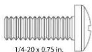
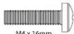
| Speaker Mounting Options | Threaded fasteners (M4, M5, M6, 1/4-20) and hex studs |
| Installation Required | Yes, steps include cross tube installation, extension tube installation, speaker bracket attachment |
| Safety Warnings | Choking hazard for small parts; not for purposes other than specified; improper installation may cause injury |
| Customer Support | Contact Sanus Systems Customer Service |
| Documentation | Manual available in PDF on notice-facile.com |
Frequently Asked Questions - XAS1A SANUS
User questions about XAS1A SANUS
0 question about this device. Answer the ones you know or ask your own.
Ask a new question about this device
Download the instructions for your Speaker Stand in PDF format for free! Find your manual XAS1A - SANUS and take your electronic device back in hand. On this page are published all the documents necessary for the use of your device. XAS1A by SANUS.
USER MANUAL XAS1A SANUS
natural_image
Technical line drawing of a mechanical frame with multiple cylindrical components and mounting holes (no text or symbols)Thank you for choosing the Sanus Systems XAS1A. The XAS1A is designed to mount speakers on each side of a VMDD26 VisionMount full motion TV mount. The XAS1A will support speakers weighing up to 11 kg (25 lbs.) each.

CAUTION
Do not use this product for any purpose not explicitly specified by Sanus Systems. Improper installation may cause property damage or personal injury. If you do not understand these directions, or have doubts about the safety of the installation, contact Sanus Systems Customer Service or call a qualified contractor. Sanus Systems is not liable for damage or injury caused by incorrect mounting, assembly, or use.

WARNING
This product contains small items that could be a choking hazard if swallowed. Keep these items away from young children!
natural_image
Simple line drawing of a toolbox inside a circle (no text or symbols)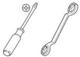
natural_image
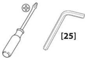
Line drawings of two screwdriver tools, one with a plus symbol and the other with a circular end (no text or labels)Supplied Parts and Hardware
Before starting assembly, verify all parts are included and undamaged. If any parts are missing or damaged, do not return the item to your dealer; contact Sanus Systems Customer Service. Never use damaged parts!
natural_image
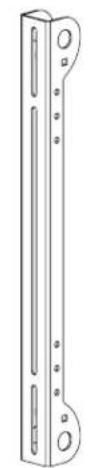
Technical line drawing of a vertical metal bracket with mounting holes and internal slots (no text or symbols)[01] × 2
![[02] x 2](/content/2026/06/1225166/images/33408d389463ef25a078816e3966f56a745f3666e75b700f283d8cf73dc45c17.jpg)
natural_image
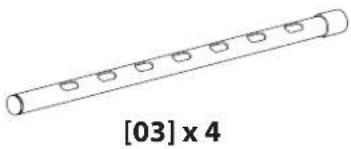
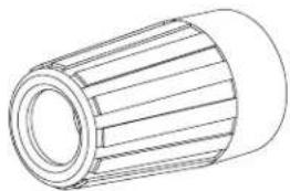
Simple line drawing of a cylindrical object with four circular indentations, labeled [03] x 4 below (no text or symbols on the object itself)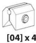
natural_image
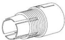
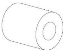
Technical line drawing of a cylindrical mechanical component with ribbed texture (no text or symbols)[05] x 4 [06] x 4

[07] x 4
[08] × 4

[09] x 4
[10] x 4

[11]×4
[12] x 4

[13] x 4
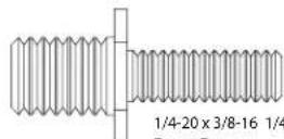
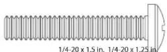
1/4-20×3/8-16 1/4-20×3/8-16
[14] x 4
natural_image
Technical drawing of a threaded bolt with no text or symbols[15] x 4

natural_image
Simple geometric diagram of two concentric circles (no text or symbols)M4 M6 M6 M4 M6M4
[16] × 4 [17] × 4 [18] × 4 [19] × 4 [20] × 4

natural_image
Simple diagram of two concentric circles with no text or symbols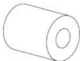


[21] x 4

1/4-20 Nyloc
[22] × 4

1/4-20
natural_image
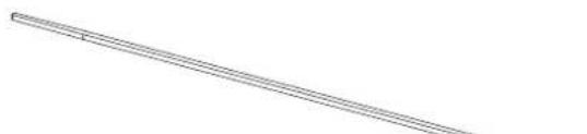
Pure diagonal line drawing without any text, numbers, or symbols[24] × 18[23] × 4

6901-100148 <01>
1: Preparation
1- 1: New Installations
If you have purchased a VMDD26 VisionMount™ Full Motion Mount, but have not installed it, begin by following the large VMDD26 installation instructions. Replace Cross Tube Installation with Step 2: Cross Tube Installation of the XAS1A instructions. When completed, refer back to this Instruction manual, starting at Step 3: Install Extension Tubes.
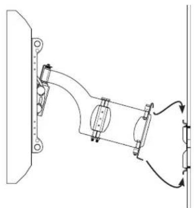
1-2: Existing Installations
natural_image
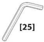
Technical line drawing of a screwdriver and a L-shaped tool, both without any text or symbolsNOTE All graphics in this section are generic and are only used to illustrate a procedure.
Disconnect all electrical connections and release all cables from any cable tie downs. Remove the safety bolt [A] as shown.
![[A]](/content/2026/06/1225166/images/31f92416c47b2acc63efeb3d42d08a572614c33830b9e7339fa91353842a2d05.jpg)
Lift the TV and arm assembly [B] off the wall plate [C] as shown Lean the assembly against a wall or other vertical surface.
![[B] [C]](/content/2026/06/1225166/images/728afe348da13e363dac63f3620fb822667aa04ecc40cb4f52f015b7711e7df1.jpg)

HEAVY! You will need assistance with this step.
Using an Allen Key, loosen the eight vise assemblies [D]. Remove the lower cross tube [E]; then, remove the upper cross tube [F] as shown.
![[D] [F] [E] [D]](/content/2026/06/1225166/images/2110323da466047aa8b19c642471770df370701a544c2e1c9a2196222098ec71.jpg)
6901-100148 <01>
2: Cross Tube Installation

Slide the cross tubes [02] into the first monitor bracket [g], through the arm assembly [H] and then through the second monitor bracket [J]. Center the cross tubes on the back of the TV. Using the Allen Key, tighten the six vise assemblies until the cross tubes no longer rotate.
![[02] [G] [02] [H] [J]](/content/2026/06/1225166/images/238353cdf1099a7ce21bb77843fb57a468abe676706a388df50ed18321194c70.jpg)
Attach the TV and arm assembly to the wall plate according to the instructions provided with the VMDD26 Full Motion Mount.

HEAVY! You will need assistance with this step.
NOTE
If you no longer have your VMDD26 Installation Manual, download one from www.Sanus.com or call Sanus Systems Customer Service.
natural_image
Technical line drawing of a mechanical assembly with no visible text or symbols3: Install Extension Tubes
Slide the four extension tubes [03] (felt end first) into the cross tubes [02].
![[02] [03] (felt end [03] [03] [02] [03]](/content/2026/06/1225166/images/0832524905f76d218a944c7ff6f77eceefc7720478e8996ea41ef30d2fce0c7d.jpg)
6901-100148 <01>
4: Install Threaded Tube Clamp & Clamp Knob
Slide the threaded tube clamps [05] onto the extension tubes [03], aligning the notches in the threaded tube clamp and cross tubes [02].
Snap the threaded tube clamps onto the cross tubes.
Thread a clamp knob [04] onto each threaded tube clamp [05]. Do not tighten at this time.
![[04] onto each threaded tube often at this time. [02] [03] [06] [05] [02] [03] [06] [05]](/content/2026/06/1225166/images/26b043a0dc9d70bfd23f7966d27473bb38969a312a2eed2a749903e0db72ff75.jpg)
5: Secure Vise Assemblies to Brackets

![[07] [04] [22] [01] 4x](/content/2026/06/1225166/images/ee005331a20c065dee31bd937abea5bc2601bc1a1b0371fc59c355a9df510f4d.jpg)
NOTE
Do not overtighten the nut [22]. The vise assembly [04] must rotate freely around the carriage bolt [07].
6: Attach Speaker Brackets
Slide the speaker brackets [01] into the extension tubes [03]. Use the Allen key to tighten the four vise assemblies [04] until the speaker brackets do not slide on the extension tubes.
NOTE
Maximum extension of the cross tubes is 162 cm (64 in.). Do not exceed the maximum extension.
![[03] [01] [04] [03]](/content/2026/06/1225166/images/ba189661f04f6be9a546d9f1faca9e3c2e73b2c044f3f8448ab3713ef81defa5.jpg)
7: Attach Speakers
7 - 1: Attach Speakers Using Threaded Fasteners
![[03] [03] [08] - [13] Determine the thread of the fastener required by threading size fastener into the back of the speaker. Stop immediately you encounter any resistance. Choose the correct thread size fastener length for your speakers. If using M4 fasteners, [12][13], be sure to install the lock washer [20].](/content/2026/06/1225166/images/6a3be1e371284295293e35b4ee2ecc97c9d26b64d95a855823f7a23f7b8c6b1b.jpg)
Determine the thread of the fastener required by threading each size fastener into the back of the speaker. Stop immediately if you encounter any resistance. Choose the correct thread size and fastener length for your speakers. If using M4 fasteners, [12] or [13], be sure to install the lock washer [20].
The speaker wires may be routed to the speaker terminals through the extension tubes [03]. Refer to the instructions provided with the large VisionMount™ Full Motion Mount for routing speaker wires.

CAUTION
Disconnect the speaker wire from the receiver or amplifier when you route it through the upper or lower extension tubes [03] to avoid damage to the speakers, amplifier, or receiver.
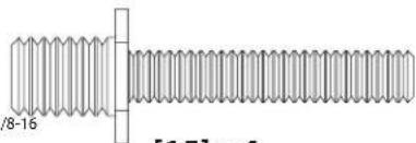
7 - 2: Attach Speakers Using Hex Studs
![[14], [15] [03] [23] Choose the correct fastener length, [14] or [15] for your speakers. The speaker wires may be routed to the speaker terminals through the extension tubes [03]. Refer to the instructions provided with the large VisionMount™ Full Motion Mount for routing speaker wires.](/content/2026/06/1225166/images/0bbdd72f4024df83e8653e6e51a3ff49aec824a18eedc6a89da36b35b5aee9ed.jpg)

CAUTION
Disconnect the speaker wire from the receiver or amplifier when you route it through the upper or lower extension tubes [03] to avoid damage to the speakers, amplifier, or receiver.
CSAV, Inc. and its affiliated corporations and subsidiaries (collectively, "CSAV"), intend to make this manual accurate and complete. However, CSAV makes no claim that the information contained herein covers all details, conditions, or variations. Nor does it provide for every possible contingency in connection with the installation or use of this product. The information contained in this document is subject to change without notice or obligation of any kind. CSAV makes no representation of warranty, expressed or implied, regarding the information contained herein. CSAV assumes no responsibility for accuracy, completeness or sufficiency of the information contained in this document.


- CAUTION
- WARNING
- Supplied Parts and Hardware
- 1: Preparation
- 1- 1: New Installations
- 1-2: Existing Installations
- 2: Cross Tube Installation
- NOTE
- 3: Install Extension Tubes
- 4: Install Threaded Tube Clamp & Clamp Knob
- 5: Secure Vise Assemblies to Brackets
- 6: Attach Speaker Brackets
- 7: Attach Speakers
- - 1: Attach Speakers Using Threaded Fasteners
Brand : SANUS
Model : XAS1A
Category : Speaker Stand