Drummer From Another Mother - Synthesizer Moog - Free user manual and instructions
Find the device manual for free Drummer From Another Mother Moog in PDF.

User questions about Drummer From Another Mother Moog
0 question about this device. Answer the ones you know or ask your own.
Ask a new question about this device
Download the instructions for your Synthesizer in PDF format for free! Find your manual Drummer From Another Mother - Moog and take your electronic device back in hand. On this page are published all the documents necessary for the use of your device. Drummer From Another Mother by Moog.
USER MANUAL Drummer From Another Mother Moog
natural_image
Abstract geometric logo design with a stylized letter 'E' inside a circle (no text or symbols)DFAM™
DRUMMER FROM ANOTHER MOTHER™
USER'S MANUAL
text_image
VCO 1-2 FV HARD CYNE TENDER DRUM / STOP AVANCE VELOCITY DFAM | DRUMMER FROM ANOTHER MOTHER | SEMI-MODULAR ANALOG PERCUSSION SYNTHESIZER meog® VCO 1 V VCO 1 V VCO 1 WIRE VCO 1 V VCO 2 V VCO 2 WIRE VCO 2 V VCO 2 WIRE VCO 2 V VCO 2 WIRE VCO 2 V VCO 2 WIRE VCO 2 V VCO 2 WIRE VCO 2 V VCO 2 WIRE VCO 2 V VCO 2 WIRE VCO 2 V VCO 2 WIRE VCO 2 V VOC CUT RESO VCA 50 RAC GLOW IN / 10000 VCC DB 1/2000 10000 10000 10000 10000 10000 10000 10000 10000 10000 10000 10000 10000 10000 10000 10000 10000 10000"I'm 100% sure that things like this (synthesizer), even though they're not living in the biological sense, there is in some sense a consciousness that we connect with."
- Dr. Robert Moog -
IMPORTANT SAFETY INSTRUCTIONS
WARNING - WHEN USING ELECTRIC PRODUCTS, THESE BASIC PRECAUTIONS SHOULD ALWAYS BE FOLLOWED:
- Read all the instructions before using the product.
- Do not use this product near water - for example, near a bathtub, washbowl, kitchen sink, in a wet basement, or near a swimming pool or the like.
- This product, in combination with an amplifier and headphones or speakers, may be capable of producing sound levels that could cause permanent hearing loss. Do not operate for a long period of time at a high volume level or at a level that is uncomfortable.
- The product should be located so that its location does not interfere with its proper ventilation.
- The product should be located away from heat sources such as radiators, heat registers, or other products that produce heat. No naked flame sources (such as candles, lighters, etc.) should be placed near this product. Do not operate in direct sunlight.
- The product should be connected to a power supply only of the type described in the operating instructions or as marked on the product.
- The power supply cord of the product should be unplugged from the outlet when left unused for a long period of time or during lightning storms.
- Care should be taken so that objects do not fall and liquids are not spilled into the enclosure through openings.
There are no user serviceable parts inside. Refer all servicing to qualified personnel only.
NOTE: This equipment has been tested and found to comply with the limits for a Class B digital device, pursuant to Part 15 of the FCC rules. These limits are designed to provide reasonable protection against harmful interference in a residential installation. This equipment generates, uses, and can radiate radio frequency energy and, if not installed and used in accordance with the instructions, may cause harmful interference to radio communications. However, there is no guarantee that interference will not occur in a particular installation. If this equipment does cause harmful interference to radio or television reception, which can be determined by turning the equipment off and on, the user is encouraged to try to correct the interference by one or more of the following measures:
—Reorient or relocate the receiving antenna.
—Increase the separation between the equipment and receiver.
—Connect the equipment to an outlet on a circuit different from that to which the receiver is connected.
—Consult the dealer or an experienced radio/TV technician for help.
CAUTION: Please note that any changes or modifications made to this product not expressly approved by Moog Music Inc. could void the user's authority granted by the FCC to operate the equipment.
TABLE OF CONTENTS
06 UNPACKING & INSPECTION
06 SETUP & CONNECTIONS
07 DFAM OVERVIEW
07 Signal Flow
08 Exploring The DFAM
13 PANEL CONTROLS & FUNCTIONS
13 Voltage Controlled Oscillators
16 Mixer
17 Voltage Controlled Filter
20 Voltage Controlled Amplifier
22 Analog 8-Step Sequencer
24 Patchbay
30 SYNCING MULTIPLE DFAMS
31 SYNCING DFAM WITH A MOTHER-32
32 USING DFAM AS A EURORACK MODULE
33 PRESETS & PATCH SHEETS
40 SPECIFICATIONS & ACCESSORIES
41 SERVICE & SUPPORT INFORMATION
UNPACKING AND INSPECTION
Be careful when unpacking your new Drummer From Another Mother so that nothing is lost or damaged. We recommend saving the carton and all packing materials in case you ever need to ship the instrument for any reason.
The Moog DFAM ships with the following items:
DFAM Semi-Modular Analog Percussion Synthesizer
Power Supply
Owner's Manual
Overlays 4.
Patch Cables.
Registration6Card
What you will need:
Headphones with a 1/4" TRS plug, or a 1/4" TS instrument cable and an amplified speaker.
A properly wired AC outlet.
SETUP AND CONNECTIONS
text_image
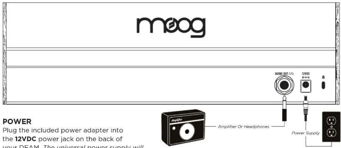
meog POWER Plug the included power adapter into the 12VDC power jack on the back of your DEAM. The universal power supply will Amplifier Or Headphones AUDIO OUT /Ω 12VDC Power SupplyPOWER
Plug the included power adapter into the 12VDC power jack on the back of your DFAM. The universal power supply will operate with a power source from 100 to 240 Volts AC, 50/60Hz. Plug the other end of the included power adapter into an AC outlet.
NOTE: There is no power switch on your DFAM. Once connected to the power supply, the unit is ON. Your DFAM is an all-analog instrument and should be allowed a few minutes to warm up before use. In cases where it has been left in a cold car overnight, for example, it may take even longer for the oscillator tuning to stabilize. Do not operate your DFAM in direct sunlight.
AUDIO OUT /
With the Master VOLUME knob turned all the way down, plug one end of a 1/4" TS instrument cable into the AUDIO OUT jack on the rear panel. Then plug the other end into an amplified speaker or mixing console input. This jack can also be used with a set of mono or stereo headphones.
WARNING: Do not use a TRS (balanced) cable for line output applications as this will cause phase cancellation and a very weak signal.
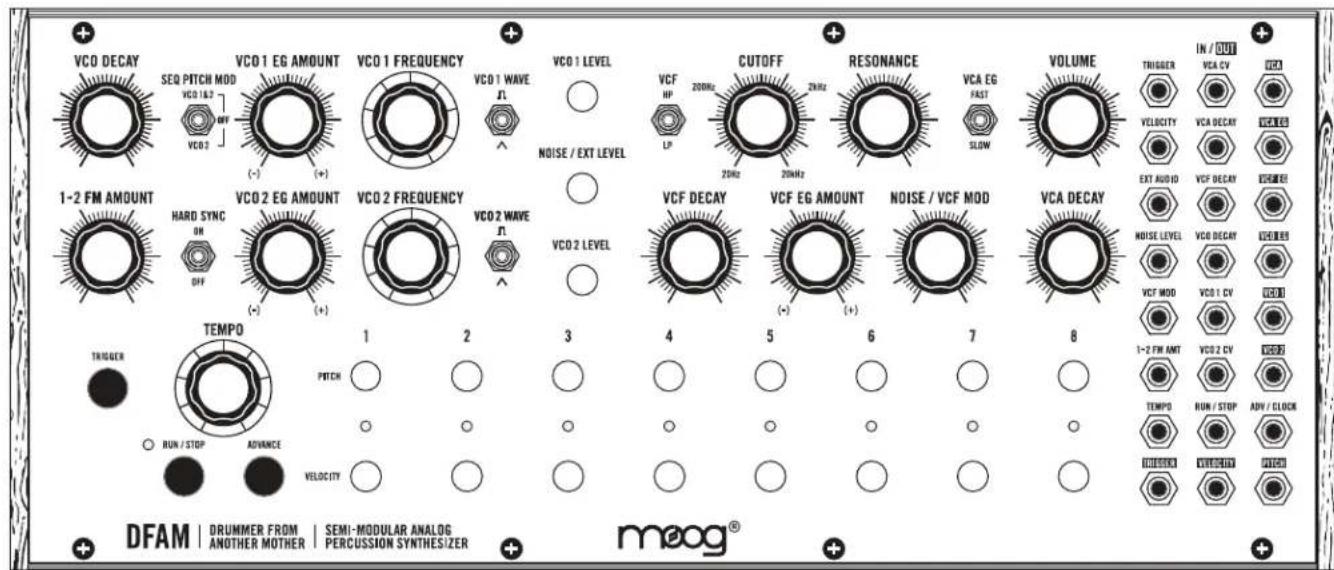
DFAM OVERVIEW
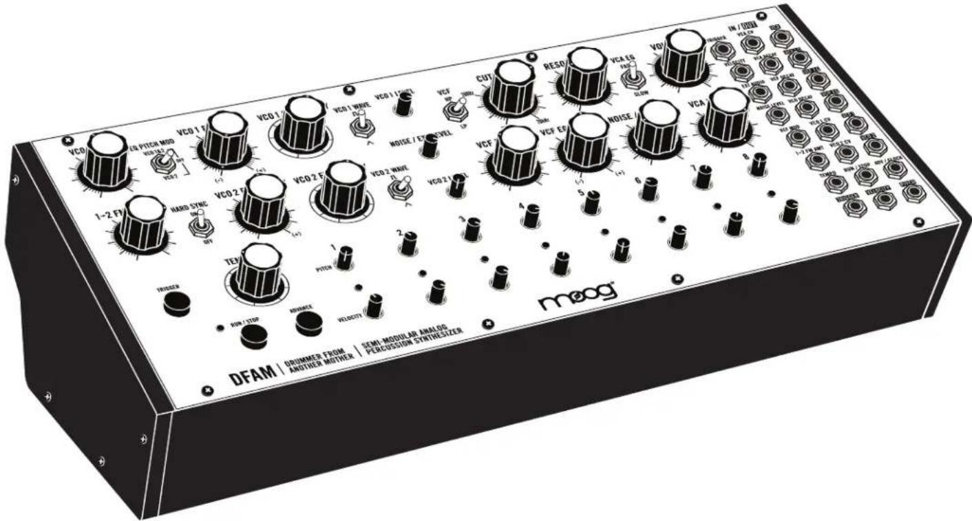
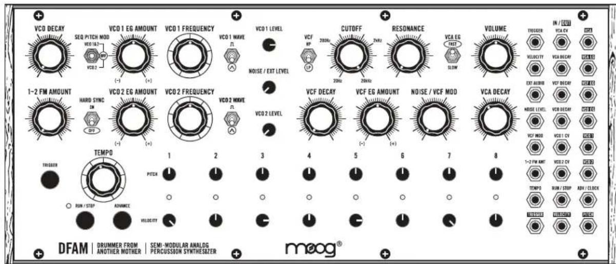
Your new Drummer From Another Mother (DFAM) is a highly-interactive, Semi-Modular Analog Percussion Synthesizer and a vibrant deviation from the traditional drum machine. As an addition to the Mother-32 family of Semi-Modular Analog Synthesizers, DFAM presents a uniquely expressive hands-on approach to percussive pattern creation.
text_image
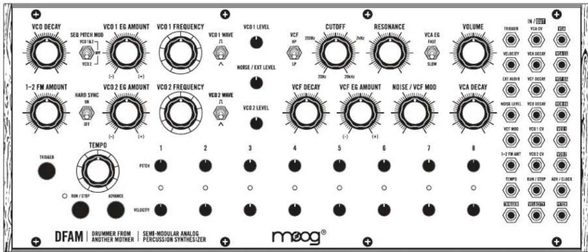
VCO DECAY SEQ PITCH MOD VCO 1&2 VCO 2 VCO 1 EG AMOUNT (-) VCO 1 FREQUENCY VCO 1 WAVE N VCO 1 LEVEL CUTOFF VCF RP 20Hz 2Hz RESONANCE VCA EG FAS SLOW VOLUME TRIGGER VELOCITY EXT AIR ON VCF DECAV VCA DECAV VCA DECAV VCA DECAV VCF MODE 1-2 FM ANT VCO 2 CV TEMP0 RUN / STOP ADV / CLOCK TEMP0 OUTDOCT TEMP0 DRUMMER FROM ANOTHER MOTHER SEM-MODULAR ANALOG PERCUSSION SYNTHESIZER DFAM | DRUMMER FROM | SEMI-MODULAR ANALOG AND/OR MOTHER | PERCUSSION SYNTHESIZER meog®SOUND SOURCES
Two Voltage Controlled Oscillators and a White Noise Generator
MODULATION
3 Envelope Generators with Voltage Controlled Decay
SOUND BLENDING
3-Channel Mixer
SEQUENCING
8-Step Analog Sequencer with Variable Pitch and Velocity per step
SOUND SHAPING
Selectable 4-pole Low Pass or High Pass Ladder Filter
PATCHING
24-point Modular Patchbay with 15 inputs and 9 outputs
DFAM SIGNAL FLOW
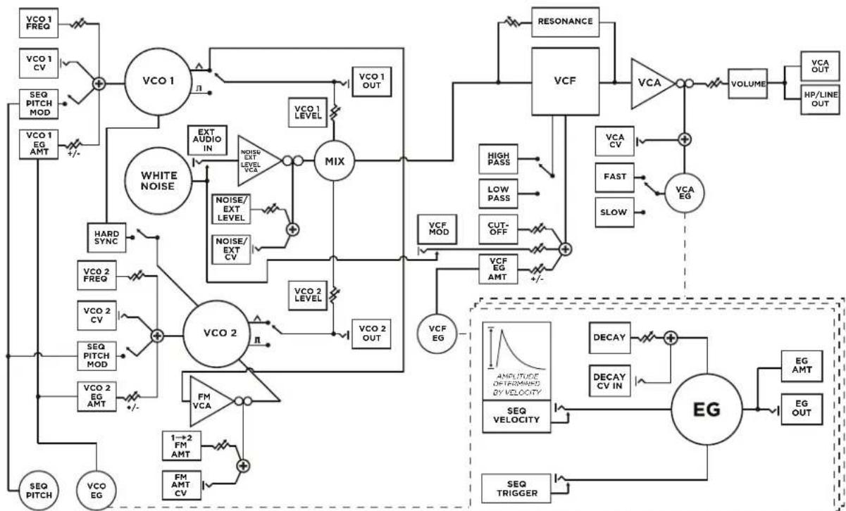
flowchart
graph TD
    A["VCO 1 FREQ"] --> B["+"]
    C["VCO 1 CV"] --> B
    D["SEQ PITCH MOD"] --> B
    E["VCO 1 EG AMT"] --> B
    B --> F["VCO 1"]
    F --> G["EXT AUDIO IN"]
    G --> H["NOISE/EXT LEVEL VCA"]
    H --> I["MIX"]
    I --> J["VCO 2"]
    J --> K["NOISE/EXT CV"]
    K --> L["HARD SYNC"]
    L --> M["VCO 2 FREQ"]
    M --> N["+"]
    O["SEQ PITCH"] --> N
    P["VCO EG"] --> N
    Q["VCO 2 EQ AMT"] --> N
    R["VCO 2 VCA"] --> S["FM VCA"]
    T["1→2 FM AMT"] --> U["FM AMT CV"]
    V["SEQ PITCH"] --> W["+/-"]
    X["VCO 1 OUT"] --> Y["VCO 1 LEVEL"]
    Z["VCO 2 OUT"] --> AA["VCO 2 LEVEL"]
    AB["RESONANCE"] --> AC["VCF"]
    AD["High PASS"] --> AE["VCA"]
    AF["Low PASS"] --> AG["VCA EV"]
    AH["CUT-OFF"] --> AI["VCF EMT"]
    AJ["VCA EG"] --> AK["+/-"]
    AL["LOW PASS"] --> AM["VCA EV"]
    AN["SLOW"] --> AO["VCA EG"]
    AP["DECAY"] --> AQ["+"]
    AR["DECAY CV IN"] --> AS["+"]
    AT["EMG"] --> AU["EG"]
    AV["SEQ TRIGGER"] --> AW["+/-"]
    AX["AMOUNTURE OF PERMID BY VELOCITY"] --> AY["SEQ VELOCITY"]
    AZ["SEQ TRIGGER"] --> BA["SEQ TRIGGER"]
EXPLORING THE DFAM
This hands-on tour of your DFAM will give you a basic foundation with which visceral rhythms can be synthesized. There are loads of tips, tricks and patching suggestions contained within this manual, but if you want to just jump to making cool sounds - go to page 33.
text_image
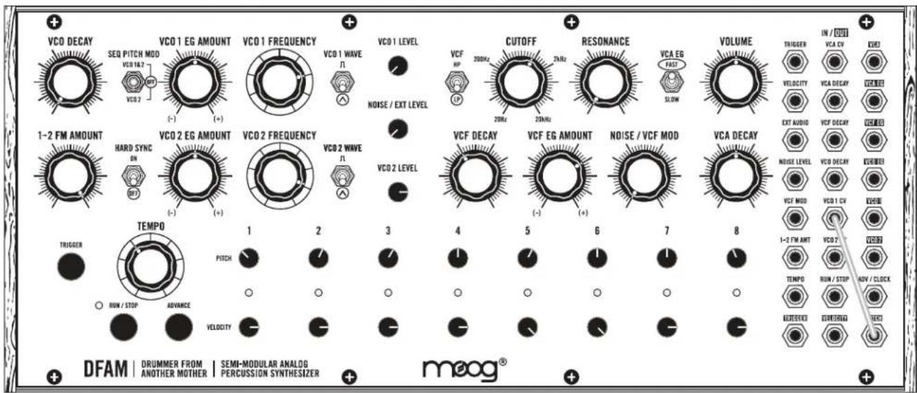
VCO DECAY SEQ PITCH MOD VCO 16.2 VCO 2 VCO 1 EG AMOUNT (-) (+) VCO 1 FREQUENCY VCO 1 WAVE F VCO 1 LEVEL NOISE / EXT LEVEL VCF HP CUTOFF 20Hz 2kHz RESONANCE 20Hz 2kHz VCA EG PART SLOW VOLUME TROGER IN / DUT VCA CV OUT VELOCITY VCA DECAV VCA 10 EXT ALUMID VCF DECAV OUT 10 1-2 FM AMOUNT HARD SYNC ON (-) (+) VCO 2 EG AMOUNT VCO 2 FREQUENCY VCO 2 WAVE F VCO 2 LEVEL VCF DECAY VCF EG AMOUNT (-) (+) NOISE / VCF MOD VCA DECAY VCA 10 OUT 10 TEMP0 RUN / STOP ADV / CLOCK TEMP0 RUN / STOP AVI / CLOCK TEMP0 DRUM/STOP DRUM/STOP DFAM | DRUMMER FROM | SEMI-MODULAR ANALOG | PERCUSSION SYNTHESIZER | meog®DEFAULT SETTINGS
Start by setting your DFAM to the Default settings shown above.
text_image
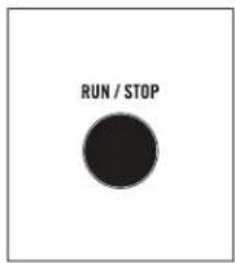
RUN / STOPSTART THE SEQUENCER
Push the RUN / STOP button to start the Sequencer.

text_image
VCO 1 FREQUENCYSET THE PITCH
Turn the VCO 1 FREQUENCY knob slowly to the left until you hear a nice, deep bass note repeating (Somewhere between 10 and 11 O'clock). This is how you set the starting pitch for an Oscillator.
NOTE: DFAM has two Oscillators, which are its primary sources of sound. It has a White Noise Generator too, but we'll get to that later.
text_image
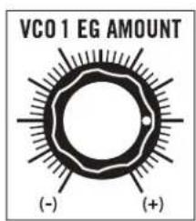
VCO 1 EG AMOUNT (-) (+)ADDING PUNCH
Now, let's add some punch to that bass note. Turn up the VCO 1 EG AMOUNT knob to 3 O'clock. This adds Envelope Modulation to the Pitch of Oscillator 1.
EXPLORING THE DFAM (Continued)

text_image
VCO DECAYThe VCO DECAY knob is going to add some more motion to the pitch of the note. It works in conjunction with the position of the VCO EG AMOUNT knobs. Try turning the VCO DECAY knob up slowly and listen to how it affects the sound. When you're done experimenting, set this knob to 9 O'clock.
TIP: The VCO EG AMOUNT knob plays an extremely important role in how the DFAM sounds and behaves. It is the difference between a silly sound and a slamming kick drum. Take some time to rotate the VCO 1 EG AMOUNT knob and
listen to how it changes the character of a sound. When you are done, be sure to set it back to 3 O'clock.
SEQUENCER VELOCITY

text_image
VELOCITYTurn all 8 Sequencer VELOCITY knobs to their maximum position. Notice how every hit now sounds the same.
RHYTHMIC VARIATION

text_image
VELOCITYMake some adjustments to all 8 of the Sequencer VELOCITY knobs and listen to how they affect both the volume and punch of the sound. They also have an enormous impact on the rhythm and feel of a sequence. Once you have a rhythm you are happy with, go to the next step.
text_image
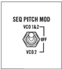
SEQ PITCH MOD VCO 1&2 OFF VCO 2SEQUENCING PITCH
It's time to start using the Sequencer to control the pitch of your bass note. Move the SEQ PITCH MOD switch to the VCO 1&2 position. You should now be hearing subtle variations in pitch for each step of the sequence.
PITCH VARIATION

text_image
PITCHMake very small adjustments to all 8 of the Sequencer PITCH knobs and listen to how they affect the sound. These knobs have an extremely wide range, which will become very handy as you experiment with your DFAM over time.
TIP: If the notes your DFAM is playing have too much punch, try gently turning the VCO 1 EG AMOUNT knob toward the center until you like what you hear.
EXPLORING THE DFAM (Continued)
text_image
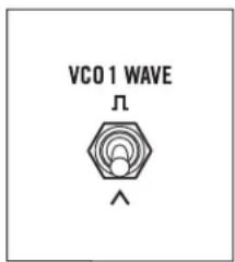
VCO 1 WAVE ΛCHANGING THE WAVEFORMS
Let's change up the sound. Set the VCO 1 WAVE switch to the SQUARE wave position and listen to how it affects the sound.

text_image
VCO 2 LEVELADDING AN OSCILLATOR
Turn the VCO 2 LEVEL knob all the way up.

text_image
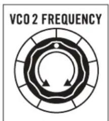
VCO 2 FREQUENCYCREATING HARMONY
Turn the VCO 2 FREQUENCY knob to the right until it sounds in tune with VCO 1 FREQUENCY.

text_image
HARD SYNC ON OFFHARD SYNC
Set the HARD SYNC switch to ON.
text_image
VCO 2 FREQUENCYLISTENING TO HARD SYNC
Now grab the VCO 2 FREQUENCY knob and turn it all the way up and down a few times. Notice that the pitch of Oscillator 2 stays directly related to the pitch of Oscillator 1 when HARD SYNC is ON.
NOTE: Because of the way that HARD SYNC works when it is ON, if the Frequency of Oscillator 2 goes below the Frequency of Oscillator 1, little to no sound will be output.
PICK A SOUND
Set the VCO 2 FREQUENCY knob to a place that makes a sound you like and then go to the next step.
EXPLORING THE DFAM (Continued)
text_image
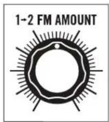
1-2 FM AMOUNTEXPLORING FM
Gently turn the 1→2 FM AMOUNT knob to 12 O'clock and listen to how the sound is changing. You are now shaking or "modulating" the pitch of Oscillator 2 with Oscillator 1.
Take a moment to experiment with how the 1→2 FM AMOUNT knob and the VCO 2 FREQUENCY knob interact with each other. Feel free to adjust these controls individually or at the same time. A lot of sounds can be created from here.
NOTE: FM is much more noticeable when HARD SYNC is set to OFF.
When you find a sound you really like, leave it where it is and we'll shape it further.
text_image
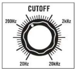
CUTOFF 200Hz 2kHz 20Hz 20kHzFILTERING SOUND
Set the Filter CUTOFF knob to 11 O'clock. Notice that the sound is now dark and flat.
text_image
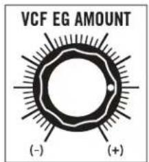
VCF EG AMOUNT (-) (+)FILTER MODULATION
Slowly increase the VCF EG AMOUNT knob to 3 O'clock. This is adding Envelope Modulation to the Filter Cutoff Frequency.

text_image
VCF DECAYFILTER ARTICULATION
The VCF DECAY knob will add a lot more motion to the timbre of this sound. Try turning it up slowly and listen to how it affects the articulation of each step in the sequence.
TIP: Adding a little RESONANCE will lighten the low end and give the Filter more of a peak.
When you're done experimenting, set the VCF DECAY knob to 10 O'clock.
text_image
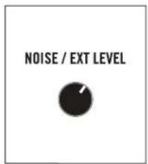
NOISE / EXT LEVELNOISE AS A SOUND SOURCE
Turn the NOISE / EXT LEVEL knob to 1 O'clock. Adding a little noise as a sound source to a percussive sound will give it a more natural attack and can also create greater sonic depth.
EXPLORING THE DFAM (Continued)

text_image
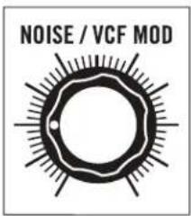
NOISE / VCF MODNOISE AS A MODULATION SOURCE
Now slowly turn the NOISE / VCF MOD knob all the way up. Notice the difference when Noise is used as a Modulation Source for the Filter. Instead of creating depth, it makes the sound seem distorted or lo-fi.
text_image
NOISE / VCF MODSET THE NOISE MODULATION
Set the NOISE / VCF MOD knob to 9 O'clock.

text_image
VCA DECAYSHORTENING VCA DECAY
Turn the VCA DECAY knob to 10 O'clock and listen to how the sound tightens up. This is because the natural Decay tails are being chopped off by the VCA, which is essentially a dynamic volume control.

text_image
VCA DECAYEXTENDING THE VCA DECAY
Turn the VCA DECAY knob to 1 O'clock and listen to how the sound opens up. This is because the natural Decay tails are allowed to pass through.

text_image
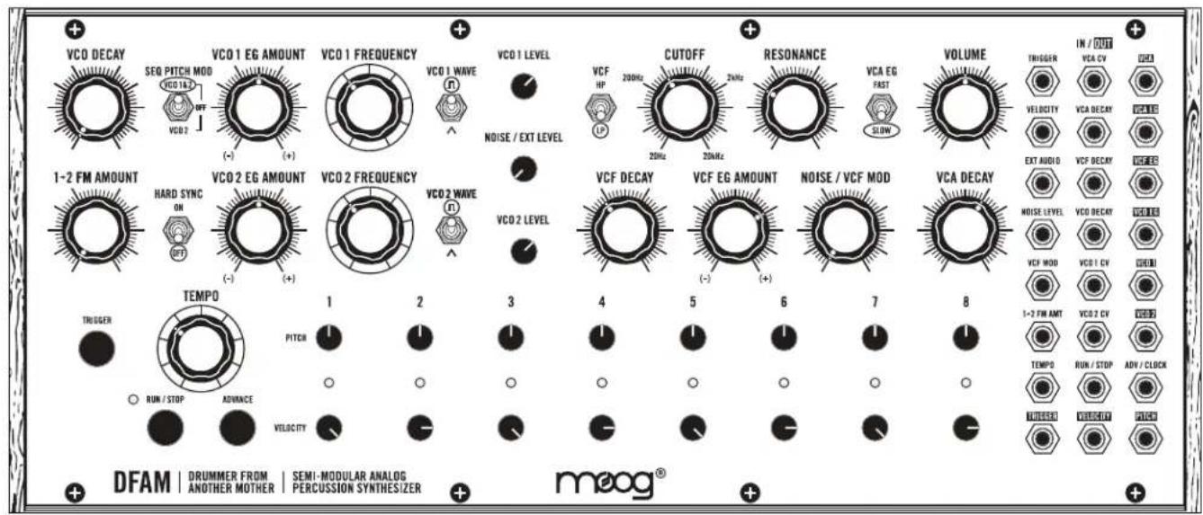
VCA EG FAST SLOWSOFTENING THE ATTACK
Set the VCA EG switch to SLOW and turn the VCA DECAY knob between 9 and 10 O'clock. Listen to how it softens the attack of the sound.
NOTE: Shorter VCA DECAY settings will result in more dramatic results when the VCA EG switch is set to SLOW.
This concludes our walkthrough.
REMEMBER: Experimentation and learning will reward you with a lifetime of rich synthesizer experiences.
PANEL CONTROLS & FUNCTIONS
■ VOLTAGE CONTROLLED OSCILLATORS (VCO)
In an analog synthesizer, oscillators are the primary source of sound. Your Drummer From Another Mother contains two Voltage Controlled Oscillators, also referred to as VCOs.

text_image
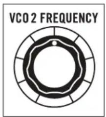
VCO 1 FREQUENCYVCO 1 FREQUENCY / VCO 2 FREQUENCY
The VCO FREQUENCY knobs specify the starting Pitch of each Oscillator over a ten-octave range. With no modulation applied, these Oscillators will track pitch accurately over multiple octaves, allowing your DFAM to be utilized for a wide range of musical applications beyond percussive sounds alone.
text_image
VCO 2 FREQUENCYFrom the panel, the Pitch of Oscillator 1 and Oscillator 2 can be modified in 3 ways:
- With the VCO FREQUENCY knobs
- With the Sequencer PITCH 1-8 knobs (See page 22)
- With the VCO EG AMOUNT knobs (See page 16)
TIP: We recommend starting with both VCO FREQUENCY knobs at their center position. This setting is the equal to the center position of the Sequencer PITCH 1-8 knobs.
WARNING: Because there are multiple ways to effect the Pitch of the Oscillators, it is possible for them to extend beyond the range of human hearing. If your DFAM stops making sound, this may be the case. Start by checking the patchbay as a
wrong patch is the most common cause of muted sound. Then, return both VCO FREQUENCY knobs to their center position. If this does not resolve the issue, set both VCO EG AMOUNT knobs to their center position. If this has not resolved the issue, set the SEQ PITCH MOD switch to OFF. If this still does not resolve the issue, we recommend going back to the Default settings found on page 8.
text_image
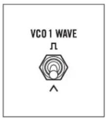
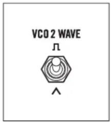
VCO1 WAVE ΛVCO 1 WAVE / VCO 2 WAVE
Each Oscillator contains two selectable Waveforms, each with a distinctly different sound or timbre. The VCO WAVE switch is used to select between the two.
TRIANGLE
The Triangle wave is a very smooth and “warm” sounding waveform consisting of odd-numbered harmonics only. Its fundamental is very strong, and its overtones are very weak, making it less harmonically complex than other waveforms. The Triangle wave is useful for crafting organic percussion sounds like toms or marimbas, and also for recreating classic analog drum sounds.
text_image
VCO 2 WAVE ΛTIP: Adding little bit of Noise as a sound source via the NOISE / EXT LEVEL knob in the Mixer is a great way to mimic classic '80s percussion sounds.
SQUARE
The Square wave provides more harmonic content and a much fuller or more aggressive sound than the Triangle wave. Its basic timbre is rich, but somewhat hollow due to the lack of even-numbered harmonics. The Square wave is useful for creating deep, hard-hitting bass sounds and for adding metallic characteristics to higher pitched FM sounds.
TIP: Use the Filter CUTOFF knob to shape Square wave sounds and to create more impactful percussive timbres.
OSCILLATOR INTERACTION
DFAM's Oscillators can interact with each other to provide new timbres and to create new sounds. HARD SYNC and FM are both useful tools that can be utilized individually or at the same time.
text_image
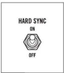
HARD SYNC ON OFFHARD SYNC
When set to ON, HARD SYNC forces the phase of Oscillator 2 to match — or to be in sync with — the phase of Oscillator 1. This forced synchronization causes the waveform of Oscillator 2 to take on a more complex waveshape as it works to stay aligned with Oscillator 1. This is useful for creating sharp, metallic, and flange-like sounds while also ensuring that the pitch of Oscillator 2 stays locked to Oscillator 1.

text_image
MASTER OSCILLATOR HARD SYNC'D OSCILLATORTIP: With the HARD SYNC switch set to ON, turn the VCO 2 FREQUENCY knob and listen. Notice that it has an effect on the timbre of Oscillator 2, while maintaining a synchronized pitch with Oscillator 1.
NOTE: When the HARD SYNC switch is set to ON and the Frequency of Oscillator 2 is set below the Frequency of Oscillator 1, Oscillator 2 may be unable to complete a wave cycle before resetting to match the phase of Oscillator 1. In this case, Oscillator 2 may have little or no output. This is especially the case with Square waveforms.
text_image
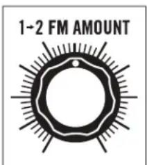
1-2 FM AMOUNT1→2 FM AMOUNT (FREQUENCY MODULATION)
A common application of modulation is pitch vibrato. This occurs when a Low Frequency Oscillator (LFO) is used to smoothly vary the pitch of an audio oscillator up and down. If the frequency of that LFO is increased enough, the pitch of the audio oscillator is being moved up and down just as before, but at an extremely fast rate. This creates new sidebands and other harmonics not present in either of the original signals.

text_image
SIGNAL FMThe sonic characteristics of FM are highly dependant on the pitch of both Oscillator 1 and Oscillator 2. Depending on the settings, the sound of FM can be described as complex, springy, bell-like, or aggressive.
Turning the 1→2 FM AMOUNT knob to the right will gradually increase the amount by which the Frequency of Oscillator 2 is being modulated by Oscillator 1.
TIP: Slowly turn the 1→2 FM AMOUNT knob to the right and listen to how it affects the sound. Now try adjusting the VCO FREQUENCY knobs and listen to how they interact with each other.
OSCILLATOR MODULATION
Changes in Oscillator pitch can come from multiple sources, but two are immediately available without patching: the Sequencer PITCH 1-8 knobs and the VCO Envelope Generator, which is itself directly affected by the Sequencer VELOCITY 1-8 knobs.

text_image
SEQ PITCH MOD VCO1&2 OFF VCO2SEQ PITCH MOD
This three-position switch determines which Oscillators are being controlled, or modulated, by the Sequencer PITCH 1-8 knobs.
VCO 1 & 2
The Sequencer PITCH 1-8 knobs are assigned to the Frequency of Oscillator 1 and Oscillator 2. This is useful for creating sequenced bass and lead lines where Oscillator 1 and Oscillator 2 are tuned in unison.
OFF
The Sequencer PITCH 1-8 knobs are not assigned to either Oscillator, but can still be used in conjunction with the PITCH CV output in the Patchbay. This selection is useful for creating droning and non-pitched percussion sounds like high-hats.
TIP: With the SEQ PITCH MOD switch set to OFF, try patching the PITCH CV output to different CV inputs and experiment with using the Sequencer PITCH 1-8 knobs as a sequenced modulation source. (See preset Quick Hats on page 33.)
VCO 2
The Sequencer PITCH 1-8 knobs are assigned to the Frequency of Oscillator 2 only. This is useful when used with FM or HARD SYNC for adding synchronized motion to a static percussion sound.

text_image
VCO DECAYVCO DECAY
Your DFAM is equipped with an Envelope Generator (EG) dedicated to modulating the Pitch of its Oscillators. The Decay Time of this EG is set using the VCO DECAY knob.
IMPORTANT NOTE: If the VCO EG AMOUNT knobs are at center position, no Pitch Modulation will occur and the VCO DECAY knob will appear to have no function. This setting can be quite useful for creating sequenced bass lines.
7 O'CLOCK (MINIMUM)
The Decay is almost immediate and its effect on the Pitch of the Oscillators is extremely snappy. This is good for adding a sharp impact to the initial attack of a sound.
9 - 10 O'CLOCK
This setting is useful for creating the punch that occurs when a drum head is hit with a drum stick or beater. As this knob approaches the 10 O'clock mark, it will introduce more of an exaggerated or rubbery sound to the attack of a note.
12 O'CLOCK AND BEYOND
These settings are useful when paired with slower sequences for creating exaggerated “booms” or spacey sounds that decay slowly over time.
NOTE: The Sequencer VELOCITY 1-8 knobs are connected to the Velocity input of the Envelope Generators, providing dynamic variations to both the Amplitude and Decay Time of the VCO Envelope Generator.
text_image
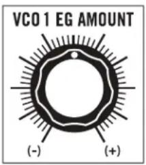
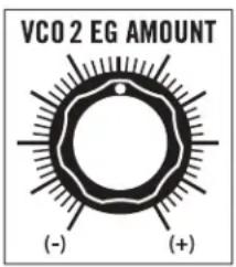
VCO 1 EG AMOUNT (-) (+)VCO 1 EG AMOUNT / VCO 2 EG AMOUNT
This pair of knobs determines how much effect the VCO Envelope Generator will have on the Pitch of Oscillator 1 and Oscillator 2, respectively. All AMOUNT knobs on DFAM are bipolar, meaning that they have both positive (+) and negative (-) modulation values available.
CENTER POSITION
No Envelope is applied to the Pitch of the Oscillator and its Frequency remains steady.
text_image
VCO2 EG AMOUNT (-) (+)(+) AMOUNT
As the VCO EG AMOUNT knob is rotated to the right of center, more Envelope Modulation is applied to the Pitch of the Oscillator. This results in larger jumps or spikes in pitch as each note is played, creating sounds that may be perceived as harder hitting, more aggressive or exaggerated.
NOTE: The VCO DECAY knob will determine how quickly the jump, or spike in pitch falls back to its original note.
(-) AMOUNT
As the VCO EG AMOUNT knob is rotated to the left of center, negative Envelope Modulation is applied to the Pitch of the Oscillator. This results in dips or large drops in pitch as each note is played, creating sounds that may be perceived as boingy or somewhat videogame-esque in character.
NOTE: The VCO DECAY knob will determine how quickly the drop, or dip, in pitch rises back to its original note.
TIP: Using lower VCO EG AMOUNT values will result in more natural percussion sounds, while larger values will result in more exaggerated and extreme sounds.
MIXER
In addition to Level knobs for VCO 1 and VCO 2, your Drummer From Another Mother's Mixer also includes a Level knob for its built-in White Noise Generator, which is useful for creating snare drums and high-hats, and also for adding depth and attack to pitched percussion sounds.
NOTE: Your DFAM is an all-analog instrument. Varying levels in the Mixer section will have an effect on the overall sound. Lower levels will result in increased headroom and dynamics, while higher levels will produce a more aggressive and clipped sound.
text_image
VCO 1 LEVELVCO 1 LEVEL
Use this knob to set the level of Oscillator 1.
NOTE: The Square Wave will be perceived as louder than the Triangle Wave. This is due to differences in harmonic content and is completely normal.
MIXER (Continued)

text_image
NOISE / EXT LEVELNOISE / EXT LEVEL
This knob is used to set the level of the White Noise Generator. Its value can also be controlled via the NOISE LEVEL CV input (VCA) on the Patchbay.
An External Audio signal can be used in place of the White Noise Generator by connecting it to the EXT AUDIO input jack on the DFAM Patchbay. The level of the External Audio signal would then be attenuated using this knob.
NOTE: The EXT AUDIO input jack is a 3.5mm TS input and will not work with a
standard 1/8" TRS headphone-style cable. Because this is a unity gain input designed for Eurorack signal levels, an external audio source applied to this input should be 10V peak to peak. Signals lower than this (an MP3 player for instance) will need to be amplified prior to being input to the EXT AUDIO jack for proper volume performance levels.
text_image
VCO 2 LEVELVCO 2 LEVEL
Use this knob to set the level of Oscillator 2.
NOTE: The Square Wave will be perceived as louder than the Triangle Wave. This is due to differences in harmonic content and is completely normal.
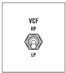
■ VOLTAGE CONTROLLED FILTER (VCF)
Your Drummer From Another Mother features a Voltage Controlled Ladder Filter that can be used in either Low Pass or High Pass mode. The purpose of this Filter is to dynamically shape the timbre of a sound by selectively removing harmonic content above or below the Filter's manually selected Cutoff Frequency.
text_image
VCF HP LPVCF
This switch is used to determine whether the Filter is in Low Pass or High Pass mode.
LP (LOW PASS)
In this mode, harmonic content above the Filter's Cutoff Frequency is attenuated, allowing only lower frequencies to pass. This mode is ideal for sculpting thick, dark, or natural sounds.
HP (HIGH PASS)
In this mode, harmonic content below the Filter's Cutoff Frequency is attenuated, allowing only higher frequencies to pass. This mode is ideal for crafting bright, thin, or snappier sounds.
VOLTAGE CONTROLLED FILTER (VCF) (Continued)
text_image
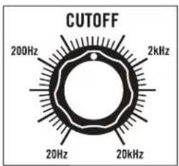
CUTOFF 200Hz 2kHz 20Hz 20kHzCUTOFF
The CUTOFF knob specifies the Frequency at which the Filter begins to attenuate (or reduce) sound in either the Low Pass or High Pass mode.
NOTE: The 4-pole Ladder Filter provides 24dB of attenuation per octave beginning at the Filter's Cutoff point.
LOW PASS MODE
As the Filter CUTOFF knob is turned to the right, the top end of the Filter will open, resulting in a brighter and more articulate sound, while retaining lower frequency harmonics. As the Filter CUTOFF knob is turned to the left, the Filter will close, resulting in a thicker or dark sound.
HIGH PASS MODE
As the Filter CUTOFF knob is turned to the right, low frequency harmonics are removed, creating a bright and more cutting sound. As the Filter CUTOFF knob is turned to the left, low frequency information is allowed to pass while retaining a bright upper spectrum of sound.
WARNING: The Filter CUTOFF knob can be set manually from 20Hz to 20kHz — roughly the same range as human hearing. Certain Filter and Modulation settings can cause DFAM to seem as if it is not making sound. If you think this is the case, set the Filter CUTOFF knob and the VCF EG AMOUNT knob to center position. If this does not resolve the issue, try setting the VCF switch to LP. If this still does not resolve the issue, we recommend going back to the Default settings found on page 8.
text_image
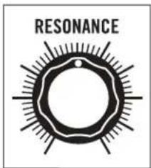
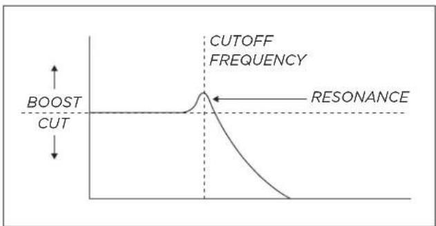
RESONANCERESONANCE
The RESONANCE knob determines how much signal is routed from the Filter's output back to its input. As the RESONANCE knob is turned to the right, a peak or harmonic boost at the Filter's Cutoff frequency is created and bass frequencies may be attenuated.
TIP: Resonance settings above 3 O'clock in LOW PASS mode will cause the Filter to self oscillate, creating a Sine Wave that can be used as an additional sound
source. (See preset Filter As An Oscillator on page 35.)
line
| Condition | Value | | ------------- | ----- | | CUTOFF FREQUENCY | Peak | | RESONANCE | Baseline |NOTE: In HIGH PASS mode, the RESONANCE knob does not have the same scaling as in LOW PASS mode. With the RESONANCE knob set to its maximum position, self-oscillation begins with the Filter CUTOFF knob set to approximately 1kHz. This is normal.
VOLTAGE CONTROLLED FILTER (VCF) (Continued)

text_image
VCF DECAYVCF DECAY
The VCF Envelope Generator is dedicated to modulating the Cutoff Frequency of the Filter. The Decay time of this EG is set using the VCF DECAY knob. This value may also be affected by the Sequencer VELOCITY 1-8 knobs. These Velocity levels are connected to the Velocity inputs of the Envelope Generators, providing an additional source of voltage control to both the Amplitude and Decay Time of the VCF EG.
IMPORTANT NOTE: If the VCF EG AMOUNT knob is at center position, no Filter modulation will occur, and the VCF DECAY knob will appear to have no function.
7 O'CLOCK (MINIMUM)
The Decay is almost immediate and its effect on the Filter is minimal. This is good for adding a gentle tap, click, or pop to the beginning of a sound.
10 O'CLOCK
This setting is useful for creating a sharp slap or crack to the initial attack of a sound.
12 O'CLOCK
This setting creates a more natural sweep of the Filter and is useful for allowing the decay of kick drums, toms, and other sounds to ring through naturally.
PAST 12 O'CLOCK
These settings cause the Filter to remain open for an extended period of time and are ideal for crafting aggressive or long-tailed sounds.
TIP: Turning the RESONANCE knob to the right will exaggerate any modulation of the Filter's Cutoff Frequency. This is useful for adding more motion or "squawk" to a sound.
NOTE: VCF Decay times range from 10ms to 10 seconds. How much of that effect can be heard is dependant on the VCF EG AMOUNT settings.
text_image
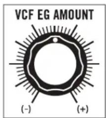
VCF EG AMOUNT (-) (+)VCF EG AMOUNT
This knob determines how much effect the VCF Envelope Generator will have on the Cutoff Frequency of the Filter. All AMOUNT knobs on DFAM are bipolar, meaning that they have both positive (+) and negative (-) values available.
CENTER POSITION
No Envelope is applied to the Filter's Cutoff Frequency.
(+) AMOUNT
As the VCF EG AMOUNT knob is rotated to the right of center, more Envelope
Modulation is applied to the Filter's Cutoff Frequency. This causes the Filter Cutoff Frequency to be increased, regardless of the VCF switch setting.
Positive VCF EG AMOUNT settings result in larger jumps or spikes in timbre as each note is played, creating sounds that may be perceived as more articulate, dynamic, or aggressive.
NOTE: The VCF DECAY knob determines how quickly the change in timbre returns to its original value over time.
VCF EG AMOUNT (Continued)
(-) AMOUNT
As the VCF EG AMOUNT knob is rotated to the left of center, negative Envelope Modulation is applied to the Filter's Cutoff Frequency. This causes the Filter Cutoff Frequency to be decreased, regardless of the VCF switch setting.
Negative VCF EG AMOUNT settings result in dips or large drops in Filter Frequency as each note is played, creating sounds that may be perceived as blooming, boingy, or somewhat videogame-esque in character.
NOTE: The VCF DECAY knob determines how quickly the change in timbre returns to its original value over time.
text_image
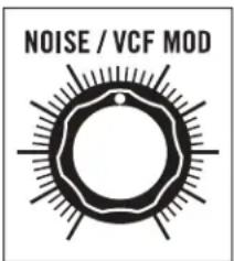
NOISE / VCF MODNOISE / VCF MOD
The Filter's Cutoff Frequency can be Modulated using the onboard Noise Generator, resulting in dirty, distorted, or lo-fi sounds. It is also useful for adding sizzle to cymbal sounds. Turning the NOISE / VCF MOD knob to the right determines how much the Filter's Cutoff Frequency is being modulated (or shaken) by the Noise Generator.
By patching into the VCF MOD input jack on the Patchbay, any control signal can modulate the Filter's Cutoff Frequency. Utilizing this patchpoint will
override Noise as the Modulation Source and will cause the NOISE / VCF MOD knob to now determine how much the Filter's Cutoff Frequency is being modulated by the new signal that has been patched into the VCF MOD input jack.
TIP: Try patching out of VCO 2 into the VCF MOD input. With the NOISE / VCF MOD knob set at maximum, listen to how the Pitch of Oscillator 2 affects the sound of the Filter. (See preset FM Toys on page 34.)
■ VOLTAGE CONTROLLED AMPLIFIER (VCA)
The VCA controls the volume of your DFAM. Its output level is determined by the VCA Envelope Generator and by the values set per step on the Sequencer VELOCITY 1-8 knobs. In addition to Decay Time, the VCA Envelope Generator also offers two selectable speeds for its Attack Time.

text_image
VCA EG FAST SLOWVCA EG
This switch is used to determine the Attack Time of the VCA EG.
FAST
In this position, the Attack Time of the VCA EG is set to 1ms. This setting is ideal for creating quick and articulate sounds with immediate snap and punch such as high-hats and kick drums.
NOTE: 1ms is the same Attack Time utilized by the VCO and VCF Envelope Generators.
SLOW
In this position, the Attack Time of the VCA EG is set to 100ms. This setting is effective for crafting sounds with softer attacks such as soft mallets, brushed snares, or gong sounds.
TIP: When used with sequenced bass sounds, the SLOW VCA setting can subtly emulate the effect of Glide. (See preset Sequenced Bass on page 34.)

text_image
VCA DECAYVCA DECAY
The third and final Envelope Generator in your DFAM is dedicated to modulating the Output volume of the VCA. The Decay time of this EG is set using the VCA DECAY knob. This value may also be affected by the Sequencer VELOCITY 1-8 knobs. These Velocity levels are connected to the Velocity inputs of the Envelope Generators, providing an additional source of voltage control to the Amplitude and Decay time of the VCA EG.
7 O'CLOCK (MINIMUM)
The Decay is nearly immediate and will result in little sound being output. This setting is ideal for crafting short sounds with sharp attacks, such as tight hi-hats.
9 O'CLOCK
Sound is now audible for a brief moment. This setting is useful for creating short blips, hits, and claps where a small portion of the body of a sound is desirable.
10 O'CLOCK
This setting allows a greater amount of sound to pass over time while still remaining percussive and tight. It is ideal for short, but hard-hitting thumps and tuned percussion sounds.
11 O'CLOCK
Sounds are now able to ring out and resonate. The decaying “note” of a pitched percussion sound is now much easier to hear, while the punch of the sound is still prominent. This setting is useful at faster tempo settings.
12 O'CLOCK
Sounds are now able to ring out over a long period of time and the more musical resonances of DFAM can be heard. This setting is particularly useful when creating percussion sounds that share both low and high frequency information.
PAST 12 O'CLOCK
Sounds begin to wash together in an almost drone-like manner, while retaining their individuality. Settings above 12 O'Clock are useful for creating deep, musical experiences where note articulation and dynamics are crafted in the Filter.
TIP: Patch the PITCH CV output into the VCA DECAY input and use the Sequencer PITCH 1-8 knobs to vary the feel of a sound. (See preset Quick Hats on page 33.)
text_image
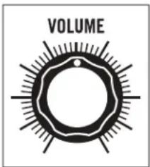
VOLUMEVOLUME
Use the VOLUME knob to a set a comfortable headphone listening level, or to adjust the final output level of your DFAM.
■ ANALOG 8-STEP SEQUENCER
Your Drummer From Another Mother includes an all-analog 8-Step Sequencer with two rows of knobs. One is for PITCH; the other is for VELOCITY. Together, they provide the tools for crafting dynamic and expressive rhythmic percussion patterns.
text_image
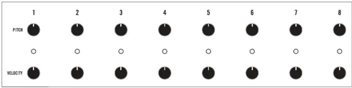
1 PITCH 2 0 VELOCITY 3 0 0 1 4 0 0 5 0 0 6 0 0 7 0 1STEP CONTROLS
Each Sequencer step (1—8) features a PITCH knob, a VELOCITY knob, and an LED that indicates the currently active step.
NOTE: In order for the Sequencer to effect the Pitch of the Oscillators in your DFAM, the SEQ PITCH MOD switch must be set to VCO 1&2 or VCO 2.
PITCH
PITCH knob values set to the right of center will add to the value of the VCO FREQUENCY knob, raising the Pitch for that step only. Values to the left of the center position will subtract from the VCO FREQUENCY knob, lowering the Pitch for that step.
NOTE: The Sequencer PITCH 1-8 knobs have roughly a 10-octave range (+/- 5 Volts). This voltage is also available at the PITCH CV output on your DFAM patchbay.
VELOCITY
The values specified by the Sequencer VELOCITY 1-8 knobs determine the Velocity level of each step as it played. The Velocity value is connected to the Velocity input and sets the Amplitude of all three Envelope Generators: the VCO EG, the VCF EG, and the VCA EG. Low Velocity settings will create quieter and less impactful sounds, while higher Velocity settings will create much louder and hard-hitting sounds. If the VELOCITY 1-8 knobs are turned to their minimum position, DFAM will not output sound.
TIP: Try varying Velocity values between steps on any sequence for a more lifelike behavior. Sequencer steps with higher Velocity values may cause the Envelope Generators to have slightly longer Decay times. Lower Velocity values may not be audible.
NOTE: The full range of each Velocity knob is 0 Volts to 5 Volts. This voltage is also available at the VELOCITY output on your DFAM patchbay.
text_image
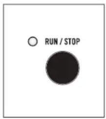
RUN / STOPRUN / STOP
Pressing the RUN / STOP button will cause the Sequencer to begin playing from the current step (indicated by a Red LED), and at the current Tempo. If the Sequencer is already running, pressing the RUN / STOP button will halt playback of the Sequencer.
NOTE: The red LED adjacent to the RUN/STOP button indicates whether the Sequencer is running (lit) or stopped (unlit).
ANALOG 8-STEP SEQUENCER (Continued)
text_image
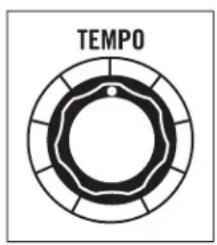
TEMPOTEMPO
The TEMPO knob sets the Sequencer playback speed, which is continuously variable from .7Hz to 700Hz. Assuming each step represents a 16th note, the Tempo can be set from roughly 10 BPM to about 10,000 BPM.
TIP: Try patching from the PITCH CV or VELOCITY CV output, into the TEMPO CV input. The Sequencer PITCH 1-8 or Sequencer VELOCITY 1-8 knobs will now determine the length of each step in the sequence. Be patient, this one can be tricky! (See preset Swing Time on page 36.)

text_image
ADVANCEADVANCE
With Sequencer playback stopped, pressing the ADVANCE button will manually cycle to the next step of the Sequence without triggering each note it passes.
NOTE: An external clock source can be connected to the ADV/CLOCK input on the DFAM patchbay. This input can also be used to advance the Sequencer to the next step, allowing for different timings and rhythmic patterns to be created using an external clock source like the Mother-32.
text_image
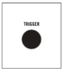
TRIGGERTRIGGER
With Sequencer playback stopped, pressing the TRIGGER button will Trigger the current Sequencer Step (indicated by the LED) without advancing to the next step. This makes it simple to fine-tune settings for a specific step by playing it as many times as needed while adjustments are made.
■ PATCHBAY

text_image
IN / OUT TRIGGER VCA CV VCA VELOCITY VCA DECAY VCA EG EXT AUDIO VCF DECAY VCF EG NOISE LEVEL VCO DECAY VCO EG VCF MOD VCO 1 CV VCO 1 1-2 FM AMT VCO 2 CV VCO 2 TEMPO RUN / STOP ADV / CLOCK TRIGGER VELOCITY PITCHPATCHBAY
The DFAM Patchbay is equipped with 24 x 3.5mm patch points, which allow for extended synthesis capabilities and modular interconnectivity. There are 15 inputs LABELED in standard text, and 9 outputs identified by REVERSE
The Patchbay is designed to work with 3.5mm patch cables only. A pack of five is included with your DFAM. If you should need more, 6" and 12" packs of Moog cables are available for purchase at authorized Moog dealers.
NOTE: When patching, it is OK to split an output signal with a "Mult", a TS to dual TS "Y" cable, or by using cables with stackable plugs. Connect only one output signal to a CV input to prevent over-voltages.
AVAILABLE INPUTS
TRIGGER, VCA CV, VELOCITY, VCA DECAY, EXT AUDIO, VCF DECAY, NOISE LEVEL, VCO DECAY, VCF MOD, VCO 1 CV, 1→2 FM AMT, VCO 2 CV, TEMPO, RUN / STOP, ADV / CLOCK.
AVAILABLE OUTPUTS
VCA, VCA EG, VCF EG, VCO EG, VCO 1, VCO 2, TRIGGER, VELOCITY, PITCH.
text_image
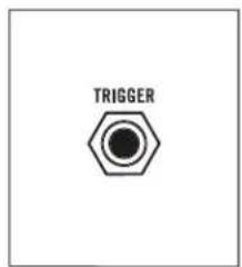
TRIGGERTRIGGER (TRIGGER INPUT)
This input will Trigger all three DFAM Envelope Generators at the currently selected Sequencer Step Velocity level without causing DFAM to advance to the next step in a sequence. This is useful when connecting to external sequencers.
INPUT
0 to +5V Pulse or Gate signal (+10V tolerant)
NOTE: The TRIGGER input is normalled (or hard-wired) to the Sequencer Clock Signal and then routed to the Envelopes and the TRIGGER output.

text_image
VCA CVVCA CV (VCA CONTROL VOLTAGE INPUT)
This input allows a control voltage to be applied to DFAM's output VCA, providing another means of varying or modulating the overall volume or timbre of the sound.
INPUT
0 to +8V Control Voltage
NOTE: This input is summed with the internal VCA EG control signal, which may cause certain patches to "clip" the VCA. This may or may not be desirable.
PATCHBAY (Continued)
text_image
VCAVCA (AUDIO OUTPUT)
This is the main audio output of the internal VCA set by the VOLUME knob.
OUTPUT
-5V to +5V Audio Signal at typical Eurorack levels

text_image
VELOCITYVELOCITY (VELOCITY CONTROL VOLTAGE INPUT)
This input controls the maximum amplitude of DFAM's Envelope Generators, and is one of the keys to DFAM's highly dynamic and expressive sound.
INPUT
0V to +5V Control Voltage
NOTE: The VELOCITY input is normalled (or hard-wired) to the Sequencer VELOCITY 1-8 knobs.

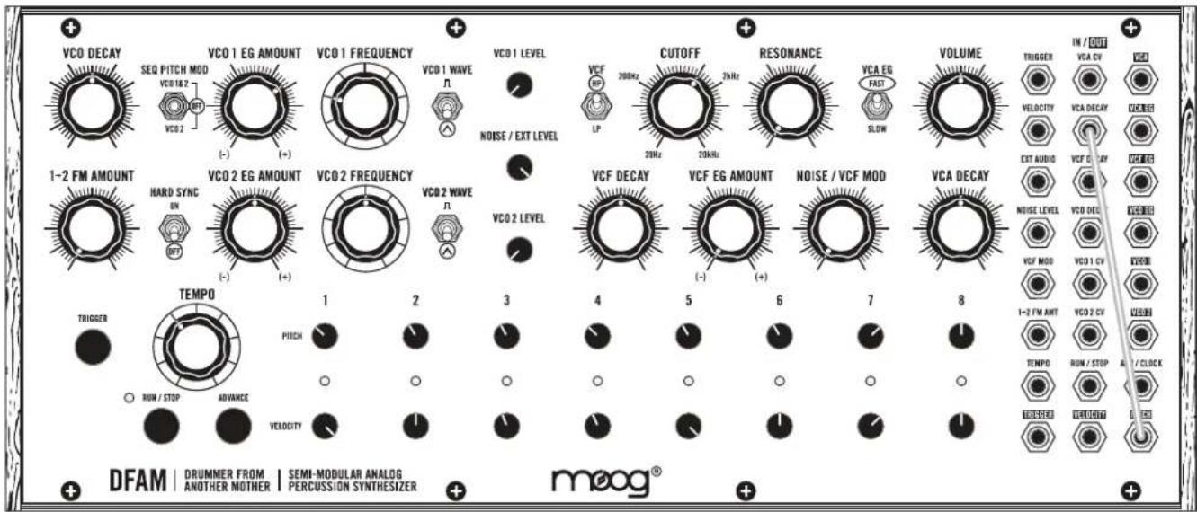
text_image
VCA DECAYVCA DECAY (VCA DECAY CONTROL VOLTAGE INPUT)
This input determines the Decay Time of the VCA EG and is useful for adding variations to non-pitched percussion patterns such as hi-hats.
INPUT
-5V to +5V Control Voltage
NOTE: The VCA DECAY input is summed with the manual VCA DECAY knob.
Setting the VCA DECAY knob to its middle position will offer the widest range
of values from an external CV signal.

text_image
VCA EGVCA EG (VCA EG CONTROL VOLTAGE OUTPUT)
This output provides a copy of the control voltage used to modulate the VCA internally.
OUTPUT
0V to +8V Control Voltage
NOTE: The VCA EG output voltage is based on the Sequencer VELOCITY 1-8 knobs, the VCA DECAY knob, and the VCA EG SLOW / FAST switch.
text_image
EXT AUDIOEXT AUDIO (EXTERNAL AUDIO INPUT)
Plugging an External Audio source into this jack removes the Noise Generator from the signal path and replaces it with the External Audio Signal. The volume of this signal is then controlled by the NOISE / EXT LEVEL knob in the DFAM Mixer.
INPUT
10V peak to peak audio signal
NOTE: Because this is a unity gain input designed for typical Eurorack signal levels, an external audio source applied to this input should be 10V peak to peak. Signals lower than this (an MP3 player for instance) will need to be amplified prior to being input to the EXT AUDIO jack for proper volume performance levels.

text_image
VCF DECAYVCF DECAY (VCF DECAY CONTROL VOLTAGE INPUT)
This input determines the Decay Time of the VCF EG and is useful for creating large variations in timbre for more complex sounds.
INPUT
-5V to +5V Control Voltage
NOTE: The VCF DECAY input is summed with the manual VCF DECAY knob.
Setting the VCF DECAY knob to its middle position will offer the widest range
of values from an external CV signal.
text_image
VCF EGVCF EG (VCF EG CONTROL VOLTAGE OUTPUT)
This output provides a copy of the control voltage used to modulate the VCF internally.
OUTPUT
0V to +8V Control Voltage
NOTE: The VCF EG output voltage is informed by the Sequencer VELOCITY 1-8 knobs and the VCF DECAY knob.

text_image
NOISE LEVELNOISE LEVEL (NOISE LEVEL CONTROL VOLTAGE INPUT)
This input modulates the value of the NOISE / EXT LEVEL knob in the Mixer section regardless of whether it is controlling the Noise level, or the level of an External Audio Signal connected via the EXT AUDIO input jack.
INPUT
0 to +8V Control Voltage
NOTE: A voltage applied to the NOISE LEVEL input is added to the position of the manual NOISE / EXT LEVEL knob in the mixer section. It is possible to clip the Noise Level VCA which may or may not be desirable.

text_image
VCO DECAYVCO DECAY (VCO DECAY CONTROL VOLTAGE INPUT)
This input determines the Decay Time of the VCO EG and is useful for adding pitched dynamics to various tuned percussion sounds.
INPUT
-5V to +5V Control Voltage
NOTE: The VCO DECAY input is summed with the manual VCO DECAY knob.
Setting the VCO DECAY knob to its middle position will offer the widest range of values from an external CV signal.
PATCHBAY OVERVIEW (Continued)
text_image
VCO EGVCO EG (VCO EG CONTROL VOLTAGE OUTPUT)
This output provides a copy of the control voltage used to modulate the VCOs internally.
OUTPUT
0V to +8V Control Voltage
NOTE: The VCO EG output voltage is informed by the Sequencer VELOCITY 1-8 knobs and the VCO DECAY knob.
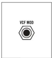
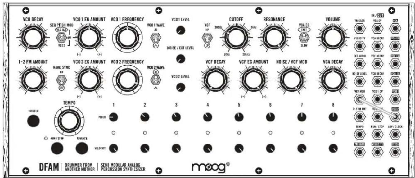
text_image
VCF MODVCF MOD (VCF MODULATION CONTROL VOLTAGE INPUT)
Plugging a control voltage into this jack replaces the Noise Generator as a hard-wired modulation source for the VCF. The maximum amount of modulation applied to the Filter will still be controlled by the NOISE / VCF MOD knob.
INPUT
-5V to +5V Control Voltage
NOTE: The VCF MOD input is the only means of directly applying a control voltage to the Filter's Cutoff Frequency. For complete CV control over the Filter, ensure that the NOISE / VCF MOD knob is set to its maximum position.
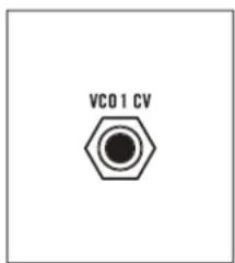
text_image
VCO1 CVVCO 1 CV (VCO 1 CONTROL VOLTAGE INPUT)
This input provides 1V/Octave control over the Pitch of Oscillator 1. It is summed with the VCO 1 FREQUENCY knob, the VCO 1 EG AMOUNT knob, and the individual Sequencer PITCH 1-8 knobs (if the SEQ PITCH MOD switch is set to VCO 1&2).
INPUT
-5V to +5V Control Voltage
NOTE: For accurate 1V/Octave control over the Pitch of Oscillator 1, set the VCO 1 FREQUENCY and VCO 1 EG AMOUNT knobs to their middle positions, and ensure that the SEQ PITCH MOD switch is set to OFF or VCO 2.
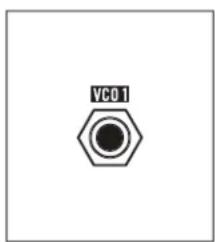
text_image
VC01VCO 1 (VCO 1 SIGNAL OUTPUT)
This is the direct output of Oscillator 1. It can be used as a sound source or as a modulation source.
OUTPUT
-5V to + 5V (10V peak to peak)
NOTE: The VCO 1 output is affected by the VCO 1 FREQUENCY knob, the VCO 1 WAVE switch, the VCO 1 EG AMOUNT knob, and the individual Sequencer PITCH 1-8 knobs (if the SEQ PITCH MOD switch is set to VCO 1&2).
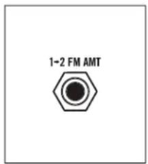
text_image
1-2 FM AMT1→2 FM AMT (VCO 1 TO VCO 2 FREQUENCY MODULATION AMOUNT INPUT)
This input modulates the value of the 1→2 FM AMOUNT knob to determine the amount of modulation (Linear FM) applied to Oscillator 2 by Oscillator 1.
INPUT
0V to +8V Control Voltage
NOTE: A voltage applied to the 1→2 FM AMT input is summed with the position of the manual 1→2 FM AMT knob.

text_image
VCO 2 CVVCO 2 CV (VCO 2 CONTROL VOLTAGE INPUT)
This input provides 1V/Octave control over the Pitch of Oscillator 2. It is summed with the VCO 2 FREQUENCY knob, the VCO 2 EG AMOUNT knob, and the individual Sequencer PITCH 1-8 knobs (if the SEQ PITCH MOD switch is set to VCO 1&2 or to VCO 2).
INPUT
-5V to +5V Control Voltage
NOTE: For accurate 1V/Octave control over the Pitch of Oscillator 2, set the VCO 2 FREQUENCY and VCO 2 EG AMOUNT knobs to their middle positions, and ensure that the SEQ PITCH MOD switch is set to OFF.

text_image
VC02VCO 2 (VCO 2 SIGNAL OUTPUT)
This is the direct output of Oscillator 2. It can be used as a sound source or as a modulation source.
OUTPUT
-5V to +5V (10V peak to peak)
NOTE: The VCO 2 output is affected by the VCO 2 FREQUENCY knob, the VCO 2 WAVE switch, the VCO 2 EG AMOUNT knob, and the individual Sequencer PITCH 1-8 knobs (if the SEQ PITCH MOD switch is set to VCO 1&2 or to VCO 2).

text_image
TEMPOTEMPO (CLOCK VCO CONTROL VOLTAGE INPUT)
This input provides 1V/Octave control over the Frequency of the Sequencer Clock VCO. This allows the Clock speed (Tempo) to be controlled by an external source all the way into audio rates.
INPUT
-5V to +5V Control Voltage
NOTE: A voltage applied to the TEMPO input is summed with the position of the TEMPO knob.
PATCHBAY OVERVIEW (Continued)

text_image
RUN / STOPRUN / STOP (GATE INPUT)
This input allows an external voltage to start and stop the DFAM Sequencer. When a +5V signal is applied to this input, the Sequencer will play from its current pattern location for the duration that the voltage is applied. When a 0V signal is applied to this input, the Sequencer will stop at its current pattern location.
INPUT
0V to +5V Gate (+10V tolerant)
NOTE: An external Clock Signal applied here will advance the steps of the pattern in the same way repeatedly pressing the RUN/STOP button does, but the Internal Clock is NOT synchronized.
text_image
ADV / CLOCKThis input allows the DFAM to be synchronized to an external clock source such as another DFAM or a Mother-32. When the input of a clock's rising edge is detected, the Sequencer pattern is advanced by one step. In this mode, the TEMPO knob is ignored.
INPUT
0V to +5V Clock Signal (+10V tolerant)
NOTE: Slowly changing signals may be ignored. An example of this would be an Accent assigned to the Assignable output jack on the Mother-32.
text_image
TRIGGERTRIGGER (TRIGGER OUTPUT)
This output provides a pulse derived from the Sequencer Clock that can be used as a clock source for synchronizing to other instruments, or as a Trigger signal. Each time a new note is played via the sequencer, a +5V Trigger signal is output both to DFAMs Envelope Generators and to the TRIGGER output jack.
OUTPUT
0V to +5V pulse (roughly 1ms in width)
text_image
VELOCITYVELOCITY (SEQUENCER VELOCITY CONTROL VOLTAGE OUTPUT)
This output provides a voltage that varies based on the VELOCITY setting of the currently selected Sequencer step.
OUTPUT
0V to +5V Control Voltage
text_image
PITCHPITCH (SEQUENCER PITCH CONTROL VOLTAGE OUTPUT)
This output provides a voltage that varies based on the Pitch setting of the currently selected Sequencer step.
OUTPUT
-5V to +5V Control Voltage
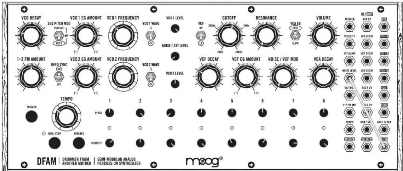
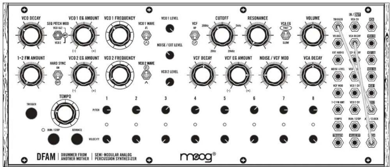
SYNCING MULTIPLE DFAMS

text_image
IN / OUT TRIGGER VCA CV VCA VELOCITY VCA DECAY VCA EG EXT AUDIO VCF DECAY VCF EG NOISE LEVEL VCO DECAY VCO EG VCF MOD VCO 1 CV VCO 1 1-2 FM AMT VCO 2 CV VCO 2 TEMPO RUN / STOP ADV / CLOCK TRIGGER VELOCITY PITCH IN / OUT TRIGGER VCA CV VCA VELOCITY VCA DECAY VCA EG EXT AUDIO VCF DECAY VCF EG NOISE LEVEL VCO DECAY VCO EG VCF MOD VCO 1 CV VCO 1 1-2 FM AMT VCO 2 CV VCO 2 TEMPO RUN / STOP ADV / CLOCK TRIGGER VELOCITY PITCHTo Sync multiple DFAM units together, simply patch from the TRIGGER output on the Patchbay of the Primary unit, into the ADV / CLOCK input on the Secondary unit.
PRIMARY UNIT SECONDARY UNIT
text_image
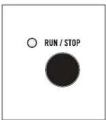
RUN / STOPSECONDARY UNIT
Press RUN / STOP on the Secondary unit first. This will ensure that it is ready to play when it begins receiving a Clock signal from the Primary unit.
text_image
RUN / STOPPRIMARY UNIT
Press RUN / STOP on the Primary unit. Both units should now be playing in sync.
SYNCING DFAM WITH A MOTHER-32
text_image
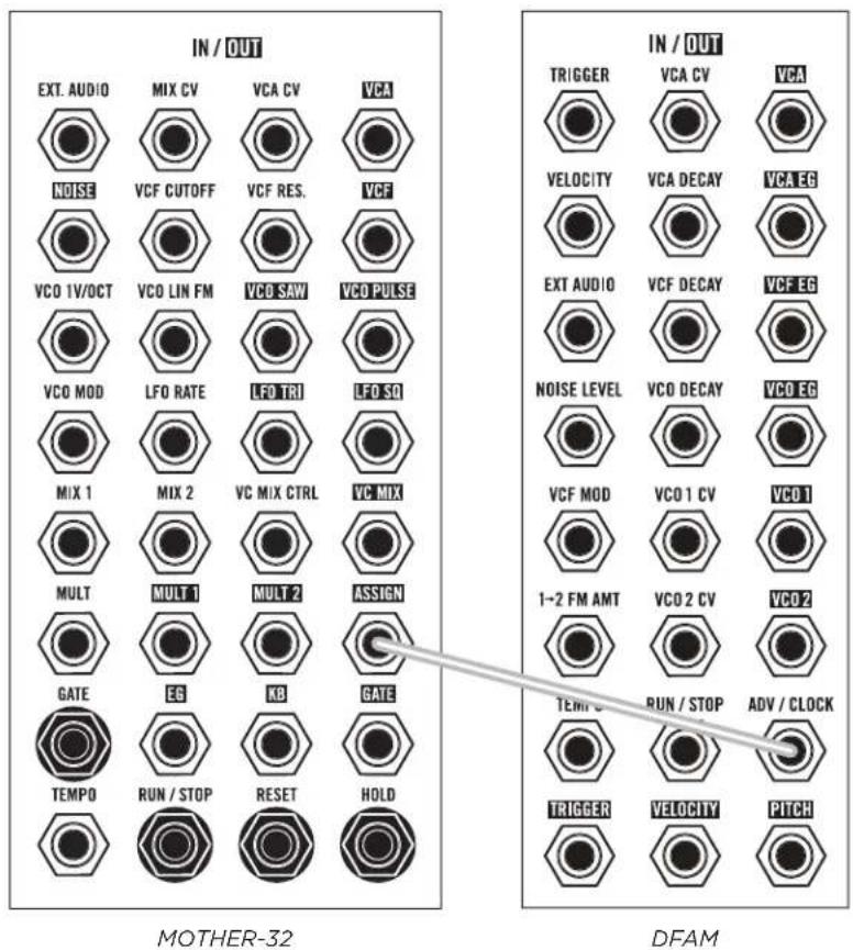
IN / OUT EXT. AUDIO MIX CV VCA CV VCA NOISE VCF CUTOFF VCF RES. VCF VCO 1V/OCT VCO LIN FM VCO SAW VCO PULSE VCO MOD LFO RATE LFO TRI LFO SCI MIX 1 MIX 2 VC MIX CTRL VC MIX MULT MULT 1 MULT 2 ASSIGN GATE EG KB GATE TEMPO RUN / STOP RESET HOLD IN / OUT TRIGGER VCA CV VCA VELOCITY VCA DECAY VCA EG EXT AUDIO VCF DECAY VCF EG NOISE LEVEL VCO DECAY VCO EG VCF MOD VCO 1 CV VCO 1 1~2 FM AMT VCO 2 CV VCO 2 TEMP U RUN / STOP ADV / CLOCK TRIGGER VELOCITY PITCH MOTHER-32 DFAMTo Sync your DFAM to a Mother-32, simply patch from the ASSIGN output jack on the Mother-32 Patchbay, into the ADV / CLOCK input on the DFAM.
IMPORTANT NOTE: You will need to ensure that the Mother-32's Assignable output is set to transmit clock. To learn more about Mother-32's Assignable output, see pages 44, 49, and 50 in the Mother-32 User's Manual.

text_image
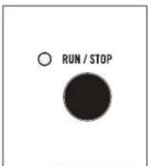
RUN / STOPDFAM
Press RUN / STOP on your DFAM. This will ensure that it is ready to play when it begins receiving a Clock signal from the Mother-32.
text_image
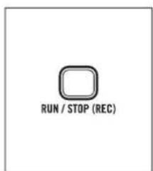
RUN / STOP (REC)MOTHER-32
Press RUN / STOP on the Mother-32. Both units should now be playing in sync.
TIP: Mother-32 can transmit different clock divisions depending on its internal settings. Experimenting with these clock divisions allows DFAM to play in sync with Mother-32, but at a division of the master tempo.
USING DFAM AS A EURORACK MODULE
Your Drummer From Another Mother can be removed from its case, and easily installed into a Eurorack system as a 60HP module. Before doing this, it is important to note that the DFAM draws a maximum of 230mA from a +12V supply. It does not use the -12V supply at all.
Make sure there is enough headroom on the +12V supply in your system to power the DFAM. You will need to know the current rating of the system's +12VDC supply, and the current draw of the +12VDC supply from all modules in the system combined. The sum of all current draw at +12VDC should never exceed the power supply rating. Note that it is good practice to leave some headroom to reduce stress on the supply.
Moog accepts NO responsibility or liability for improperly installed modules.
TO INSTALL THE DFAM IN A EURORACK SYSTEM
- Disconnect external power from the unit.
- Remove the eight black M3 screws on the front panel and keep them somewhere safe.
- Lift the panel slowly from the bottom so you can see the two cables going to the Front Panel module.
- Disconnect the two cables from the front panel. Now the module is free from its enclosure.

text_image
10 1 PIN 1 STRIPE +1 +2 6 9 -1 ZWN3 8 88 88 P3 1- Look at the back of your DFAM module. There is a 10-pin power header on the back of the PCB that accepts a 10-pin Eurorack power ribbon cable.
-
Connect PIN-1 (-12V) of the power ribbon cable to PIN-1 of the DFAM Eurorack power header. The darkened wire (typically red) on the ribbon cable indicates the PIN-1 (-12V) side of the cable.
-
After power is connected, your DFAM may be installed into the rails of the Eurorack system case with the eight black M3 screws.
- Once fully installed, you may power up your Eurorack system.
PRESETS
Please note that your DFAM is 100% analog, and as a result, each unit has subtle sonic differences due to component tolerances that make it unique. This means that two different units set the same way may sound slightly different. This is normal.
NOTE: Additional presets and blank patch sheets can be downloaded at www.moogmusic.com.
MUSIC BOX
text_image
VCO DECAY SEQ PITCH MOD VCO 16.2 VCO 2 VCO 1 EG AMOUNT (-) VCO 1 FREQUENCY VCO 1 WAVE N VCO 1 LEVEL NOISE / EXT LEVEL VCF HP CUTOFF 20kHz 2kHz RESONANCE 20kHz VCA EG FAST SLOW VOLUME TRIGGER IN / OUT VCA CV VEGET VELOCITY VCA DECAV VCEBEI EXT AUDIO VCF DECAV VCEBEI 1-2 FM AMOUNT HARD SYNC ON VCO 2 EG AMOUNT (-) VCO 2 FREQUENCY VCO 2 WAVE N VCO 2 LEVEL VCF DECAY VCF EG AMOUNT (-) NOISE / VCF MOD VCA DECAY NOISE LEVEL VCD DECAV VCEBEI VCF MOD VCO 1 CV VCEBEI 1-2 FM AMT VCO 2 VCEBEI TEMP0 PITCH RUN / STOP ADVANCE VELOCITY DFAM | DRUMMER FROM | SEMI-MODULAR ANALOG | PERCUSSION SYNTHESIZER | + DFAM | ANOTHER MOTHER | semi-modular analog | meog® | + meog®NOTES
• The Sequencer PITCH 1-8 knobs determine the Pitch of VCO 1
- Small tweaks to the Pitch of the sequence will have a large impact on tonality
- Try turning the VCO 2 FREQUENCY knob and listen to how it affects the sound
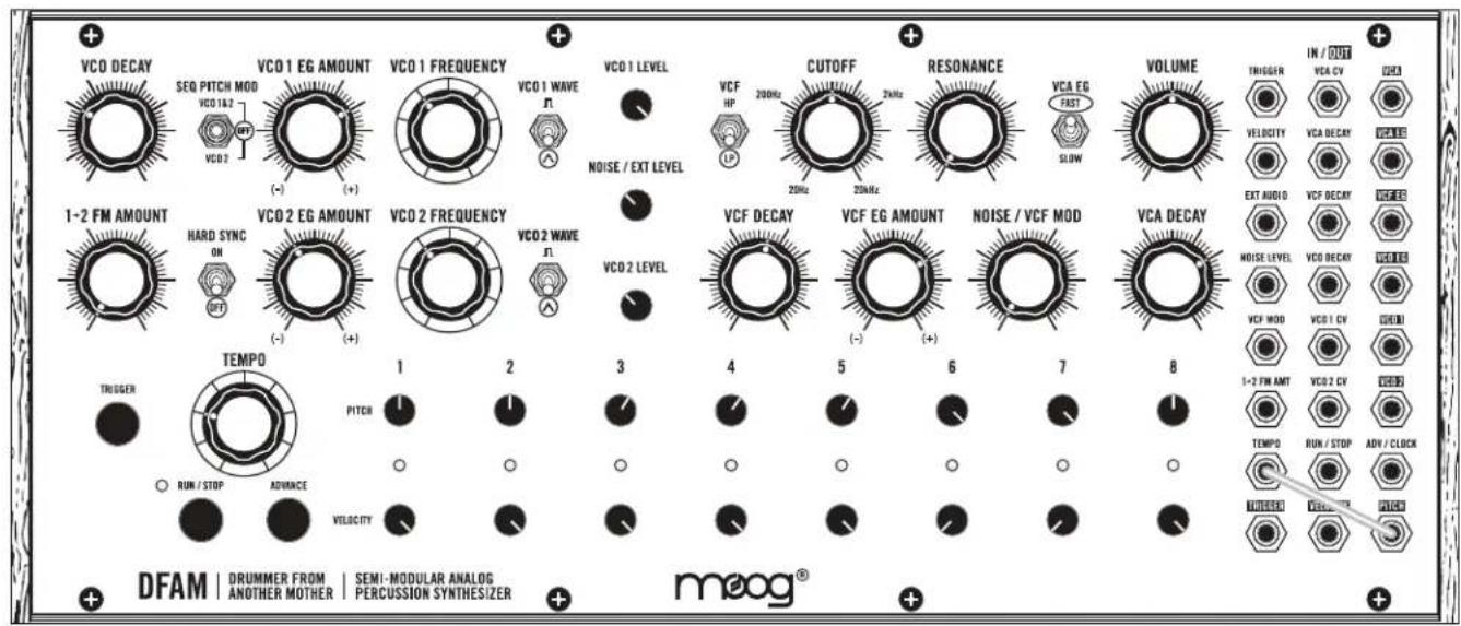
QUICK HATS
text_image
VCO DECAY SEQ PITCH MOD VCO 1&2 VCO 2 VCO 1 EG AMOUNT (-) VCO 1 FREQUENCY VCO 1 WAVE n VCO 1 LEVEL NOISE / EXT LEVEL VCF RP LP CUTOFF 20kHz 2kHz RESONANCE 20kHz 2kHz VCA EG FAST SLOW VOLUME TRIGGER IN / OUT VCA CV VELOCITY VCA DECAV VZUBE3 EXT AUDIO VCF EG AMOUNT VCO 1&2 VCO 1&2 VCO 2 EG AMOUNT (-) VCO 2 FREQUENCY VCO 2 WAVE n VCO 2 LEVEL VCF DECAY VCF EG AMOUNT (-) VCO 1&2 VCA DECAY VCO 1&2 VCO 1&2 VCO 1&2 VCO 1&2 TEMP0 1 2 3 4 5 6 7 8 1-2 FM AMT VCO 2 CV TEMP0 RUM / STOP AVANCE o o o o o o o o o o o o o o o o o o o o o o o o o o o o o o o o o o o o o o o o o o o o o o o o o o o o o o o o o o o o o o o o o o o o o o o o o o o o o o o o o o o o o o o o o o o o o o o o o o o o o DRUMMER FROM | SEMI-MODULAR ANALOG | ANOTHER MOTHER | PERCUSSION SYNTHESIZER | DFAM | DRUMMER FROM | SEMI-MODULAR ANALOG | meog®NOTES
• The Sequencer PITCH 1-8 knobs determine tightness per step
- Experiment with the Sequencer VELOCITY 1-8 knobs
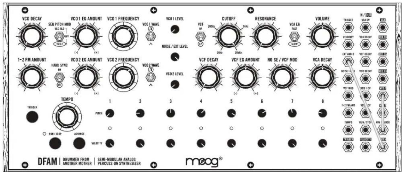
FM TOYS
text_image
VCO DECAY SEQ PITCH MOD VCO 1.62 VCO 2 VCO 1 EG AMOUNT (-) VCO 1 FREQUENCY VCO 1 WAVE A VCO 1 LEVEL NOISE / EXT LEVEL VCF HP 20MHz CUTOFF 2MHz RESONANCE 20MHz VCA EG FAST SLOW VOLUME TRIGGER IN / OUT VCA CV VCA VELOCITY VCA DECAY WACC EXT AUDIO VCP DECAY WACC 1-2 FM AMOUNT HARD SYNC ON VCO 2 EG AMOUNT (-) VCO 2 FREQUENCY VCO 2 WAVE VCO 2 LEVEL TEMP0 1 2 3 4 5 6 7 8 VCA DECAY NOISE LEVEL VCO DECAY VCO 1.62 VCA VCF MOD 1-2 FM AMT VCO 1.62 VCO 2.62 TEMP0 RUN / STOP ADV / CLOCK RUM / STOP ADVANCE VELOCITY DFAM | DRUMMER FROM | SEMI-MODULAR ANALOG | PERCUSSION SYNTHESIZER | moog®NOTES
• VCO 2 is modulating the Filter Cutoff
- Try adjusting the VCO 2 FREQUENCY knob
- Listen to the difference between the VCF in LP and HP mode
SEQUENCED BASS
text_image
VCO DECAY SEQ PITCH MOD VCO 16.3 VCO 2 VCO 1 EG AMOUNT (-) VCO 1 FREQUENCY VCO 1 WAVE VCO 1 LEVEL NOISE / EXT LEVEL VCF HP CUTOFF 200Hz 2MHz 20MHz RESONANCE VCA EG FAST VOLUME TRIGGER IN / OUT VCA CV VCA CC VELOCITY VCA DECAV VCA CC EXT AUDIO VCF DECAY VCA CC VCA CC VCA CC VCA DECAY VCA MEL VCA MEL TEMP0 1 2 3 4 5 6 7 8 1-2 FM AMT VCO 2 DV TEMP0 RUN / STOP ADV / CLOCK UNIVERSAL VELOCITY PICKD DFAM | DRUMMER FROM | SEMI-MODULAR ANALOG | PERCUSSION SYNTHESIZER + + + + + + + + + + + + + + + + + + + + + + + + + + + + + + + + + + + + + + + + + + + + + + + + + + + + + + + + + + + + + + + + + + + + + + + + + + + + + + + + + + + + + + + + + + + + + + + + + + + + + + - DFAM | DRUMMER FROM | SEMI-MODULAR ANALOG | PERCUSSION SYNTHESIZER | + + + + + + + + + + + + + + + + + + + + + + + + + + + + + + + + + + + + + + + + + + + + + + + + + + + + + + + + + + + + + + + + + + + + + + + + + + + + + + + + + + + + + + + + + + + + + + + + + + + vco1.1.3.1.1.1.1.1.1.1.1.1.1.1.1.1.1.1.1.1.1.1.1.1.1.1.1.1.1.1.1.1.1.1.1.1.1.1.1.1.1.1.1.1.1.1.1.1.1.1.1.1.1.0NOTES
- Use the VCO FREQUENCY knobs to ensure VCO 1 and VCO 2 are exactly in tune
- Minor adjustments to the Sequencer PITCH 1-8 knobs will add motion to your bass line
- Tweak the Filter CUTOFF knob to taste
KICK / SNARE / FM OSC 2
text_image
VCO DECAY SEQ PITCH MOD VCO 16.2 OFF VCO 2 VCO 1 EG AMOUNT (-) (+) (+) VCO 1 FREQUENCY VCO 1 WAVE Ω VCO 1 LEVEL NOISE / EXT LEVEL VCF HP 200Hz 2kHz CUTOFF 20Hz 2kHz RESONANCE VCA EG FAST SLOW VOLUME TRIGGER IN / OUT VCA CV VCA VELOCITY VCA DECY VWA/BE EXT AUDIO VCF DECY VCREBES 1-2 FM AMOUNT HARD SYNC OFF VCO 2 EG AMOUNT (-) (+) (+) VCO 2 FREQUENCY VCO 2 WAVE Ω VCO 2 LEVEL VCF DECAY VCF EG AMOUNT (-) (+) (+) NOISE / VCF MOD VCA DECAY NOISE LEVEL VCO DECY VWA/BE VCF MG VCO 1 CV VGA 1-2 FW AMT VD 2 CV VDRB TEMPD RUN / STI ADV / CLK RINK / STOP ADVANCE VELOCITY DTMOS NEUTCHY TDCS DFAM | DRUMMER FROM | SEMI-MODULAR ANALOG | mooog® ANOTHER MOTHER | PERCUSSION SYNTHESIZERNOTES
• The Sequencer PITCH 1-8 knobs determine the voicing for each step
• The Sequencer PITCH 1-8 knobs also determine the Snare volume
- Turn the Sequencer VELOCITY 1-8 knobs up and down to vary the Kick pattern
FILTER AS AN OSCILLATOR

text_image
VCO DECAY SEQ PITCH MOD VCO 162 OFF VCO 2 VCO 1 EG AMOUNT (-) (+) (+) VCO 1 FREQUENCY VCO 1 WAVE N VCO 1 LEVEL NOISE / EXT LEVEL VCF HP CUTOFF 20kHz 2kHz RESONANCE 20kHz VCA EG FAST SLOW VOLUME TRIGGER IN / OUT VCA DV VECC VELOCITY VCA DECAV VEECE EXT AUDIO VCF DECAV VEEC VCA DECAV VCA DECAV VCA 1 CV VECC VCF MOD 1-2 FM AMOUNT HARD SYNC OFF VCO 2 EG AMOUNT (-) (+) (+) VCO 2 FREQUENCY VCO 2 WAVE N VCO 2 LEVEL VCF DECAY VCF EG AMOUNT (-) (+) (+) NOISE / VCF MOD VCA DECAY NOISE LEVEL VCO DECAV VECC VECC 1-2 FM AMOUNT TEMP0 PITCH ROW / STOP ADVANCE VELOCITY 1 2 3 4 5 6 7 8 TEMP0 RUN - TOP AVI / CLOCK UNLESS VEECE / CLK DFAM | DRUMMER FROM | SEMI-MODULAR ANALOG | PERCUSSION SYNTHESIZER | moog®NOTES
• The Filter CUTOFF knob is being controlled by the Sequencer PITCH 1-8 knobs
- Turn up the VCO 2 LEVEL control to add a watery wobble
- Increasing the NOISE / EXT LEVEL will add a more ghostly tone to the sound
INSANE TOMS
text_image
VCO DECAY SEQ PITCH MOD VCO 1&2 VCO 2 VCO 1 EG AMOUNT (-) (+) VCO 1 FREQUENCY VCO 1 WAVE A VCO 1 LEVEL NOISE / EXT LEVEL VCF HP 20MHz CUTOFF 2MHz RESONANCE 20MHz VCA EG FAST SLOW VOLUME TRIGGER IN / OUT VCA CV VCA VELOGI VCA DECAY WINS EXT AUDIO CP - CRY VCEER 1-2 FM AMOUNT HARD SYNC ON OPF VCO 2 EG AMOUNT (-) (+) VCO 2 FREQUENCY VCO 2 WAVE A VCO 2 LEVEL VCF DECAY VCF EG AMOUNT (-) (+) NOISE / VCF MOD VCA DECAY NOISE LEVEL VCO 1 CV VCA 1 DV VCF MOD 1-2 FM AMT VCO 2 CV TEMPD RUN / STOP A / CLOCK RUM / STOP ADVANCE VELOCITY THIGHER TEMPO 1 2 3 4 5 6 7 8 DFAM | DRUMMER FROM ANOTHER MOTHER | SEMI-MODULAR ANALOG PERCUSSION SYNTHESIZER | moog®NOTES
• VCO 2 is adding extra triggers
- Try experimenting with the VCO 2 EG AMOUNT knob
• The Sequencer PITCH 1-8 knobs determine how each hit rings out
SWING TIME
text_image
VCO DECAY SEQ PITCH MOD VCO 1&2 VCO 2 VCO 1 EG AMOUNT (-) VCO 1 FREQUENCY VCO 1 WAVE n VCO 1 LEVEL NOISE / EXT LEVEL VCF HP 200Hz CUTOFF 2MHz RESONANCE 2MHz VCA EG FAST SLOW VOLUME TRIGGER IN / OUT VCA CV VCA DECAV VELOCITY EXT AUDIO VCF DECAY VCEE HARD SYNC ON (+) (+) VCO 2 EG AMOUNT (-) VCO 2 FREQUENCY VCO 2 WAVE n VCO 2 LEVEL VCF DECAY VCF EG AMOUNT (-) VCO 1 WAVE NOISE / VCF MOD VCA DECAY NOISE LEVEL VCO DECAY WELLER VCF MOD VCD 1 CV WDR 1-2 FM AMT VCD 2 CV TEMPD RUN / STOP ADV / CLOCK RUN / STOP ADVANCE VELOCITY TEMPD TEMPD TEMPD DFAM | DRUMMER FROM | SEMI-MODULAR ANALOG | meog® ANOTHER MOTHER PERCUSSION SYNTHESIZERNOTES
• The Sequencer PITCH 1-8 knobs determine the length of each Step in a Sequence
- Lower Sequencer PITCH settings will result in extremely long step lengths
- Higher Sequencer PITCH settings will result in extremely short step lengths
SEQUENCER AS AN OSCILLATOR
text_image
VCO DECAY SEQ PITCH MOD VCO 1&2 VCO 2 VCO 1 EG AMOUNT (-) (+) (+) VCO 1 FREQUENCY VCO 1 WAVE R VCO 1 LEVEL NOISE / EXT LEVEL VCF HP 200Hz 20Hz CUTOFF 20Hz 20kHz RESONANCE VCA EG FAST SLOW VOLUME TRIGGER IN / OUT VCA CV VCA VELOCITY VCA DECAY VCA EXT AUDIO VCF DECAY VCA 1-2 FM AMOUNT HARD SYNC ON (HP) VCO 2 EG AMOUNT (-) (+) (+) VCO 2 FREQUENCY VCO 2 WAVE R VCO 2 LEVEL VCF DECAY VCF EG AMOUNT (-) (+) (+) NOISE / VCF MOD VCA DECAY NOISE LEVEL VCO DECAY VCA VCF MOD VCEL 1 CV VCEL 0 1-2 FM AMT VCEL CV TEMP0 RUN / STOP ADV / LOCK RUN / STOP ADVINCE VELOCITY TEMP0 RUN / STOP ADV / LOCK RUN / STOP DELENT VOUTOUT VCCD DFAM | DRUMMER FROM | SEMI-MODULAR ANALOG | PERCUSSION SYNTHESIZER | moog®NOTES
• The VCO 1 FREQUENCY knob controls the Sequencer Rate and Pitch
• The Sequencer PITCH 1-8 knobs alter and shape the waveform
- Add some VCO 2 LEVEL for wild sounds
TALKING DRUM

text_image
VCO DECAY SEQ PITCH MOD VCO 1&2 VCO 2 VCO 1 EG AMOUNT (-) VCO 1 FREQUENCY VCO 1 WAVE R VCO 1 LEVEL NOISE / EXT LEVEL VCF HP CUTOFF 200Hz 2MHz 20MHz RESONANCE VCA EG FAST SLOW VOLUME TRIGGER IN / OUT VCA CV VCA DECAV VELOCITY VCA DECAV OUT EXT AUDIO VCF DECAY VCA DECAV NOISE VCA DECAY OUT VCA DECAV OUT VCF MDD VCB 1 CV VCEB 1-2 FM AMT VLECCY VCEB TEMPD RUN / STOP ADV / CLOCK DRUMMER FROM ANOTHER MOTHER | SEMI-MODULAR ANALOG PERCUSSION SYNTHESIZER DFAM | DRUMMER FROM ANOTHER MOTHER | VMEOG® meog®NOTES
• VCO 2 is modulating the Filter Cutoff position
• The NOISE / VCF MOD knob determines how vocal the drum is
- Turn the RESONANCE knob down to add more thump
PRESET NAME:

text_image
VCO DECAY SEQ PITCH MOD VCO 1&2 OFF VCO 2 VCO 1 EG AMOUNT VCO 1 FREQUENCY VCO 1 WAVE VCO 1 LEVEL CUTOFF 20kHz 2kHz RESONANCE VCA EG FAST SLOW VOLUME TRIGGER IN / OUT VCA CV VCEA VELOCITY VCA DECAV VERMES EXT AUDIO VCF DECAV VCEA NOISE/EXT LEVEL HARD SYNC ON OFF VCO 2 EG AMOUNT VCO 2 FREQUENCY VCO 2 WAVE VCO 2 LEVEL VCF DECAY VCF EG AMOUNT NOISE / VCF MOD VCA DECAY NOISE LEVEL VCO DECAV VCEA VCF MOD VCO 1 CV VERM 1-2 FM ANT VCO 2 CV VERM TEMPD RUN / STOP ADV / CLOCK RUN / STOP ADVANCE VELOCITY TEMPD RUN / STOP AVOC RUSSEL VERCOUT AVOC DFAM | DRUMMER FROM | SEMI-MODULAR ANALOG | mooog® ANOTHER MOTHER | PERCUSSION SYNTHESIZERNOTES
PRESET NAME:
text_image
VCO DECAY SEQ PITCH MOD VCO 1&2 OFF VCO 3 VCO 1 EG AMOUNT VCO 1 FREQUENCY VCO 1 WAVE VCO 1 LEVEL NOISE / EXT LEVEL VCF HP CUTOFF 200Hz 2Hz 20kHz RESONANCE VCA EG FAST SLOW VOLUME TRIGGER VELOCITY EXT AUDIO VCF DECAY VCREER MOISE LEVEL VCO DECAY VCREER VCA DECAY VCT MOD 1-2 FW AMT VCO 2 CV TEMPD RUN / STOP ADV / CLOCK RUSSELL VELOCITY DRUMMER FROM ANOTHER MOTHER SEMI-MODULAR ANALOG PERCUSSION SYNTHESIZER DFAM | DRUMMER FROM | SEMI-MODULAR ANALOG | AND/OR MOTHER | PERCUSSION SYNTHESIZER moog®NOTES
PRESET NAME:

text_image
VCO DECAY SEQ PITCH MOD VCO 1&2 OFF VCO 2 VCO 1 EG AMOUNT VCO 1 FREQUENCY VCO 1 WAVE VCO 1 LEVEL CUTOFF 20kHz 2kHz RESONANCE VCA EG FAST SLOW VOLUME TRIGGER IN / OUT VCA CV VCEA VELOCITY VCA DECAV VERMES EXT AUDIO VCF DECAV VCEA 1-2 FM AMOUNT HARD SYNC ON OFF VCO 2 EG AMOUNT VCO 2 FREQUENCY VCO 2 WAVE VCO 2 LEVEL VCF DECAY VCF EG AMOUNT NOISE / VCF MOD VCA DECAY NOISE LEVEL VCO DECAV VCEA VCF MOD VCO 1 CV VERM 1-2 FM ANT VCO 2 CV VERM TEMPD RUN / STOP ADV / CLOCK RUN / STOP ADVANCE VELOCITY TEMPD RUN / STOP AVOC RUSSEL VERCOUT AVOC DFAM | DRUMMER FROM | SEMI-MODULAR ANALOG | mooog® ANOTHER MOTHER | PERCUSSION SYNTHESIZERNOTES
PRESET NAME:

text_image
VCO DECAY SEQ PITCH MOD VCO 1&2 OFF VCO 2 VCO 1 EG AMOUNT VCO 1 FREQUENCY VCO 1 WAVE VCO 1 LEVEL NOISE / EXT LEVEL VCF HP CUTOFF 200Hz 2Hz RESONANCE VCA EG FAST SLOW VOLUME TRIGGER IN / OUT VCA CV VCO VELOCITY VCA DECAV VCREER EXT AUDIO VCF DECAY VCREER MOISE LEVEL VCO DECAY VCREER VCT MOD VCO 1 CV VCO 1 1-2 FM AMT VCO 2 CV TEMPD RUN / STOP ADV / CLOCK TEMPD AVOCUT PICK DRUMMER FROM ANOTHER MOTHER | SEMI-MODULAR ANALOG PERCUSSION SYNTHESIZER DFAM | DRUMMER FROM | SEMI-MODULAR ANALOG PERCUSSION SYNTHESIZER moog®NOTES
SPECIFICATIONS
ANALOG SOUND ENGINE
SOURCES: VCO 1, VCO 2, White Noise Generator
FILTER: Selectable High Pass/Low Pass 4-pole (-24dB/Oct) Ladder Filter
MODULATION: VCO EG with Voltage Controlled Decay, VCF EG with Voltage Controlled
Decay Time, VCA EG with with Voltage Controlled Decay Time and selectable Attack Time
ANALOG SEQUENCER
CONTROL: 8 Steps with dedicated PITCH and VELOCITY knobs per step
TEMPO: 10 BPM to 10,000 BPM
OTHER: Manual Trigger and Advance buttons
PATCHBAY
JACKS: 24x 3.5mm
INPUTS: 15x 3.5mm
OUTPUTS: 9x 3.5mm
REAR PANEL
AUDIO: 1/4" TRS Headphone or 1/4" TS Instrument
POWER: Connection for external power supply
DIMENSIONS
SIZE (W X D X H): 12.57" x 4.21" x 5.24
WEIGHT: 3.5lbs
POWER SUPPLY (INCLUDED)
STYLE: Wall adaptor; barrel connection, center-pin positive
INPUT: 100 - 240VAC; 50Hz - 60Hz
OUTPUT: +12VDC; 1200mA
POWER CONSUMPTION
TYPICAL: 3.0 Watts
EURORACK SPECS
CURRENT DRAW: 230mA (maximum) from +12VDC (10-pin header)
MOUNTING DIMS: 60HP (1"/26mm Module Depth)
All specifications subject to change without notice.
ACCESSORIES
The following accessories are available at authorized Moog dealers.
2-TIER VERTICAL RACK KIT
3-TIER VERTICAL RACK KIT
GIG BAG
Moog warrants its products to be free of defects in materials or workmanship and conforming to specifications at the time of shipment. The Warranty Period is one year from the date of purchase. If, in Moog's determination, it has been more than five years since the product shipped from our factory, it will be at Moog's discretion whether or not to honor the warranty without regard to the date of the purchase. During the Warranty Period, any defective products will be repaired or replaced, at Moog's option, on a return-to-factory basis. This warranty covers defects that Moog determines are no fault of the user.
The Moog Limited Warranty applies to USA purchasers only. Outside the USA the warranty policy and associated service is determined by the laws of the country of purchase and supported by our local authorized distributor. A listing of our authorized distributors is available at moogmusic.com.
If you purchase outside of your country, you can expect to be charged for warranty as well as non-warranty service by the service center in your country.
RETURNING YOUR PRODUCT TO MOOG MUSIC
You must obtain prior approval in the form of an RMA (Return Material Authorization) number from Moog before returning any product. Email techsupport@moogmusic.com for the RMA number via email or call us at (828) 251-0090. All products must be packed carefully and shipped with the Moog supplied power adapter. The DFAM must be returned in the original inner packing including the cardboard inserts. Sorry, the warranty will not be honored if the product is not properly packed. Once you have received the RMA number and carefully packed your Moog, ship the product to Moog Music Inc. with transportation and insurance charges paid, and be sure to include your return shipping address.
MOOG MUSIC
160 Broadway St.
Asheville NC, 28801
WHAT WE WILL DO
Once received, we will examine the product for any obvious signs of user abuse or damage as a result of transport. If the product abused, damaged in transit, or is out of warranty, we will contact you with an estimate of the repair cost. Warranty work will be performed and Moog will ship and insure your product to your United States address free of charge.
HOW TO INITIATE YOUR WARRANTY
Please initiate your warranty online at www.moogmusic.com/register. If you do not have web access, please call (828) 251-0090 to register your product.
CARING FOR THE DRUMMER FROM ANOTHER MOTHER
Clean the DFAM with a soft, dry cloth only - do not use solvents or abrasive detergents. Heed the safety warnings at the beginning of the manual. Do not drop the unit.
AN IMPORTANT NOTE ABOUT SAFETY: There are no user serviceable parts in the DFAM. Refer all servicing to qualified personnel only.
©2017 MOOG MUSIC INC. | 160 Broadway St. Asheville, NC 28801
Moog is a registered trademark of Moog Music Inc.
The Moog Wordmark is a registered trademark of Moog Music Inc.
The Moog Icon is a registered trademark of Moog Music Inc.
DFAM is a trademark of Moog Music Inc.
Drummer From Another Mother is a trademark of Moog Music Inc.
All rights reserved to Moog Music Inc. on all text & graphics here within.
Phone: 828.251.0090 | Email: info@moogmusic.com | Website: www.moogmusic.com