Werkstatt-01 - Synthesizer Moog - Free user manual and instructions
Find the device manual for free Werkstatt-01 Moog in PDF.


| Product Type | Analog Synthesizer Kit |
| Brand | Moog |
| Model | Werkstatt-01 |
| Category | Synthesizer |
| Power Supply | 12V DC, 1.2A, center pin positive; included AC adapter (100-240VAC, 50-60Hz) |
| Power Consumption | 2W typical |
| Sound Engine | 100% analog, semi-modular design |
| Oscillator (VCO) | Voltage Controlled Oscillator with Saw and Pulse waveforms, Pulse Width Modulation (PWM), 8Hz-16kHz range |
| Filter (VCF) | 24dB/octave Moog Ladder low-pass filter with resonance, self-oscillating |
| Amplifier (VCA) | Voltage Controlled Amplifier with ON/EG mode switch |
| Modulation Sources | Low Frequency Oscillator (LFO) with Triangle and Square waves, Envelope Generator (EG) with Attack/Decay/Sustain |
| Keyboard | 13 keys (1 octave), low-note priority, with Glide (portamento) |
| Patch Points | Patchable header with CV and audio I/O; optional CV Expander adds 3.5mm jacks |
| Audio Output | 1/4" unbalanced TS jack |
| Controls | Knobs for frequency, cutoff, resonance, modulation amount, LFO rate, envelope attack/decay; switches for waveforms, modulation source/destination, sustain |
| Assembly | No soldering required; includes all parts and hardware; easy step-by-step instructions |
| Included Accessories | PCB, metal bottom chassis, top panel, 12V DC power adapter, hardware kit (screws, nuts, rubber feet, button caps), patch cables |
| Safety | Read instructions, keep away from water, use only included adapter, clean with dry cloth |
| Warranty | 1 year domestic (USA), varies internationally; register at moogmusic.com |
| Manufacturer | Moog Music Inc., 160 Broadway St., Asheville, NC 28801, USA |
Frequently Asked Questions - Werkstatt-01 Moog
User questions about Werkstatt-01 Moog
0 question about this device. Answer the ones you know or ask your own.
Ask a new question about this device
Download the instructions for your Synthesizer in PDF format for free! Find your manual Werkstatt-01 - Moog and take your electronic device back in hand. On this page are published all the documents necessary for the use of your device. Werkstatt-01 by Moog.
USER MANUAL Werkstatt-01 Moog
natural_image
Abstract black and white geometric logo design with circular and angular shapes (no text or symbols)WERKSTATT-01
Analog Synthesizer Kit
ASSEMBLY INSTRUCTIONS
& USER'S MANUAL
IMPORTANT SAFETY INSTRUCTIONS
WARNING - WHEN USING ELECTRIC PRODUCTS, THESE BASIC PRECAUTIONS SHOULD ALWAYS BE FOLLOWED.
- Read these instructions.
- Keep these instructions.
- Heed all warnings.
- Follow all instructions.
- Do not use apparatus near water - for example, but not limited to: near a bathtub, washbowl, or kitchen sink; in a wet basement; or near a swimming pool or the like.
- Clean only with dry cloth.
- Do not block any ventilation openings. Install in accordance with the manufacturer's instructions.
- Do not install near any heat sources such as radiators, heat registers, stoves, or other apparatus (including amplifiers) that produce heat. Do not operate this apparatus with the case in direct sunlight.
- Protect the power cord from being walked on or pinched particularly at plugs, convenience receptacles, and the point where they exit from the apparatus.
- Use attachments/accessories specified by the manufacturer. Ensure that any external equipment used in conjunction with this product is installed according to the safety specifications supplied with that equipment.
- Unplug this apparatus during lightning storms or when unused for a long period of time.
- This product, in combination with an amplifier and headphones or speakers, may be capable of producing sound levels that could cause permanent hearing loss. Do not operate for a long period of time at a high volume level or at a level that is uncomfortable.
- The product should only be connected to the AC adapter supplied with the product. Do not connect the AC adapter to an Mains AC socket-outlet that is outside the adapter's input specifications.
- Care should be taken so that objects do not fall and liquids are not spilled into the enclosure through openings. Do not expose this product to rain or moisture.
- Refer all servicing to qualified service personnel. Servicing is required when the apparatus has been damaged in any way, such as if power supply cord or plug is damaged; liquid has been spilled or objects have fallen into the apparatus; or the apparatus has been exposed to rain or moisture, does not operate normally, or has been dropped.
NOTE:
This equipment has been tested and found to comply with the limits for a Class B digital device, pursuant to part 15 of the FCC Rules. These limits are designed to provide reasonable protection against harmful interference in a residential installation. This equipment generates, uses and can radiate radio frequency energy and, if not installed and used in accordance with the instructions, may cause harmful interference to radio communications. However, there is no guarantee that interference will not occur in a particular installation. If this equipment does cause harmful interference to radio or television reception, which can be determined by turning the equipment off and on, the user is encouraged to try to correct the interference by one or more of the following measures:
— Reorient or relocate the receiving antenna.
— Increase the separation between the equipment and receiver.
- Connect the equipment into an outlet on a circuit different from that to which the receiver is connected.
— Consult the dealer or an experienced radio/TV technician for help.
CAUTION: Please note that any changes or modifications made to this product not expressly approved by Moog Music Inc. could void the user's authority granted by the FCC to operate the equipment.
TABLE OF CONTENTS
INTRODUCTION 6
ANALOG SYNTHESIZER BASICS 7
ASSEMB LY
Parts List 8
Instructions 9
WERKSTATT FEATURES AND CONTROLS
Default Settings 12
Voltage Controlled Oscillator 13
Voltage Controlled Filter 14
Voltage Controlled Amplifier 14
Oscillator Modulation 15
Filter Modulation 16
Low Frequency Oscillator 17 ____
Envelope Generator 18
Keyboard 19
Patchable Header 20
Rear Panel 21
ABOVE AND BEYOND
Interfacing with Other Synthesizers and Effects 21
Hacking & Circuit Bending 23.
SPECIFICATIONS 24
![WERKSTATT-01 ANALOG SYNTHESIZER VGO FREQ PULSE SAW VCO VWF VCF VCO MOD EG LFO SOURCE MOUNT PWM FREQ DEST LFO CATE SQUARE TRIANGLE WAVE ENVELOPE ON SUSTAIN PACK POULARITY VCA ON EQ MODE [+] [-] CV IN VCA IN VCS IN VCO EXP IN VFD IN GAT IN VCF ADD IN KB CV GUT TWO GUT GATE GUT BG GUT LED GUT VCF GUT VCO GUT CVG T OUTOFF RES VCF MOD EG LFO SOURCE MOUNT Polarity](/content/2026/05/884420/images/247edb59e9cae5f1ece9d65d00be36a6cc7d54eedc1589856ef87aa889549496.jpg)
WERKSTATT-01
The Moog Werkstatt-01 is a patchable, 100% analog synthesizer whose design is based on classic Moog circuits. Assembly is extremely simple: Anyone can quickly build this analog synthesizer with minimal tools and expertise. Through assembly and inspired investigation, the Werkstatt-01 is an excellent platform for exploring the world of analog synthesizer circuits.
A lifetime of experimentation, knob twisting, and sound design awaits.
ANALOG SYNTHESIZER BASICS
An analog synthesizer generates two types of signals: Audio signals and Control signals. Audio signals are the sounds you hear emanating from the sound creation circuits of an instrument. Control signals, on the other hand, are used to change and/or modify the settings of these circuits. Due to the analog nature of the instrument, these Control signals carry a continuously variable voltage level. These signals are referred to as Control Voltages, and most analog synthesizer components are “Voltage Controlled.” An additional type of control signal is known as a Gate, or Trigger, which is simply used to initiate an event. Changing Pitch or frequency is an example of using a Control Voltage; playing a key on a keyboard is an example of generating a Gate signal.
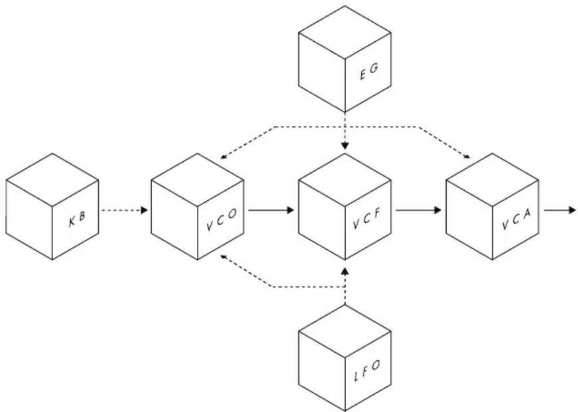
In an analog synthesizer, each set of circuits performs a particular job. The oscillators, filters, and envelopes, etc. are each self-contained modules. By design, these modules are wired together using both audio signals and control signals. However, patch points and patch cables can allow these modules to be reconnected in new ways. This is the basis for the term Modular Synthesizer. The first Moog synthesizers were modular synthesizers.
flowchart
graph TD
    KB["KB"] --> VCO["VCO"]
    VCO --> VCF["VCF"]
    VCF --> VCA["VCA"]
    VCA --> LFO["LFO"]
    VCO -.-> VCF
    VCO -.-> LFO
    VCG["EG"] --> VCF
In this diagram of the Werkstatt modules, the solid lines represent audio signals, and the dotted lines represent control signals. The definitions and functions of each module are described in the Werkstatt Features and Controls section.
ASSEM B LY
Putting together your Werkstatt is easy. No soldering is required, and all of the electronic components have been pre-assembled. The only tool you will need is a #1 Phillips [ + ] screwdriver. And while assembly is not complicated, it is important to follow each step, in order. Be mindful that you are working with electronics, so a good measure of caution and care is always in order.
A NOTE ABOUT ELECTROSTATIC DISCHARGE:
You may have noticed that little electric shock you sometimes receive when you touch something like a metal doorknob. This is called electrostatic discharge, and it can be harmful to electronic components. To protect the circuitry when you are assembling your Werkstatt, leave the circuit board in its protective anti-static sleeve until you are ready to install it. Also, take a moment to ground yourself by touching a metal surface or grounded object before you handle the circuit board.
PARTS LIST
Unpack your Werkstatt synthesizer kit and make sure all parts are present and accounted for before you get started.
A) Werkstatt-01 printed circuit board (PCB) x 1 ____
B) Bottom chassis (metal) × 1 ____
C) Top panel with silkscreened printing (metal) x 1.
D) 12 volt DC power adapter x 1.
E) Hardware kit containing:
a) Keyboard button caps x 13 ____
b) 1/4" Sheet metal screws (black) x 4
c) 1/4" Pan head machine screws (silver) x 5
d) Sheet metal screws for CV Expander (silver/pointed tip) x.2.
e) Black nylon washer x1
f) Black nylon hex nut x1
g) Rubber feet x 4
ASSEMBLY INSTRUCTIONS
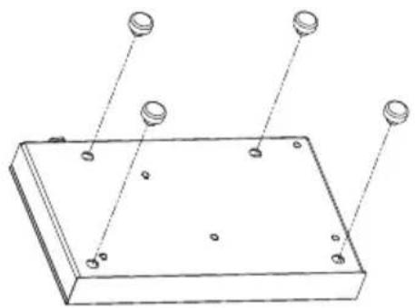
1) ATTACHING THE FEET
Attach the four rubber feet by pushing them into the holes of the Bottom Chassis and twisting.
natural_image
Technical line drawing of a rectangular electronic component with four circular features and mounting holes (no text or symbols)2) ATTACHING THE WASHER
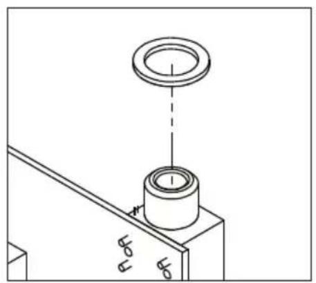
Carefully remove the printed circuit board from the protective sleeve. Take the black nylon washer and slide it onto the audio output jack.
natural_image
Technical line drawing of a mechanical assembly with a cylindrical component and a ring, no text or symbols present3) INSTALLING THE ELECTRONICS
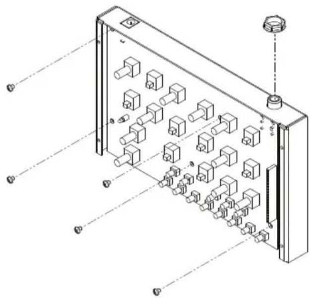
Place the Printed Circuit Board into the Bottom Chassis. Slide the audio jack through the jack hole, and be sure the five mounting holes in the Printed Circuit Board line up with the standoffs on the Bottom Chassis. Using the silver pan head machine screws (x5), loosely attach the Printed Circuit Board to the chassis. Take a moment to make sure everything is lined up neatly and correctly—including the power input jack—and then go ahead and tighten the screws.
Finally, place the black nylon hex nut on the audio jack, and hand-tighten the nut to hold the jack securely to the Bottom Chassis.
natural_image
Isometric technical diagram of a mechanical or electronic device with internal components and mounting points (no text or labels)4) POWER / LED TEST
Using only the included power supply, connect the barrel end to the power supply input of your Werkstatt; connect the other end to an AC wall outlet (100-240 Volts AC / 50-60 Hz). At this point, the red LED on the front panel (LFO) should begin blinking. If it does, you're ready to move on.
NOTE: Unplug the power supply from the Werkstatt before proceeding.
natural_image
Technical line drawing of an electrical enclosure with multiple ports and wiring (no text or symbols)5) ATTACHING KEYBOARD BUTTONS
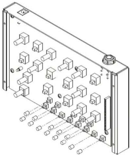
Place the 13 button caps on the keyboard buttons.
6) ADDING THE TOP PANEL
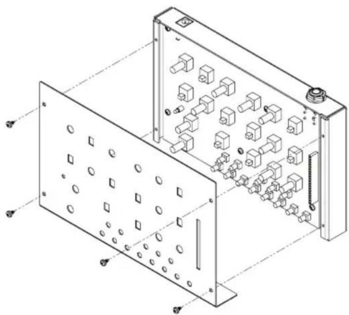
Place the Top Panel in position so that all of the knobs, switches, and keyboard buttons pass through the corresponding holes. Secure the Top Panel using the four (x4) black sheet metal screws. The screw holes in the Top Panel should line up with the screw holes in the Bottom Chassis.
NOTE: Tightening these screws may require a little extra effort the first time, as these screws must cut threads into the metal holes.
NOTE: Leave out the screws on the right side if you plan to install the CV Expander (Step 7).
natural_image
Technical line drawing of an electronic device casing with internal components and mounting holes (no text or symbols)7) ATTACHING THE CV EXPANDER
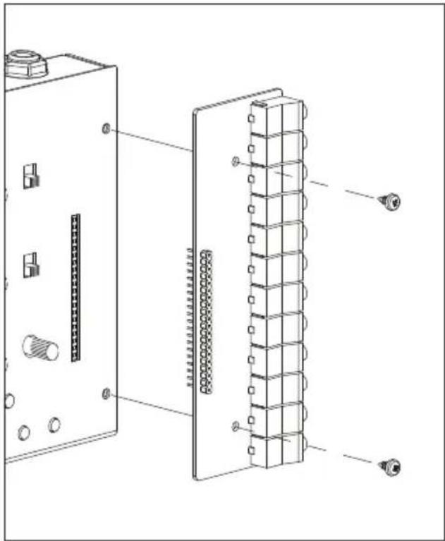
7a: Remove the two screws on the Werkstatt-01 right front panel.
NOTE: This step is only needed if you have fully attached the front panel (Step 6).
7b: Carefully plug the header pins on the bottom of the CV Expander into the expansion header of the Werkstatt-01 so that the bottom of the CV Expander circuit board is flush with the top of the front panel and the pins are fully seated in the female header.
7c: Install the two silver sheet metal screws included with this kit through the holes in the expander PCB that line up with the holes in the Werkstatt-01 panel. Tighten until they are secured, taking care not to over-tighten.
natural_image
Technical line drawing of an electronic device showing internal components and wiring (no text or symbols)8) APPLYING THE SERIAL NUMBER LABEL
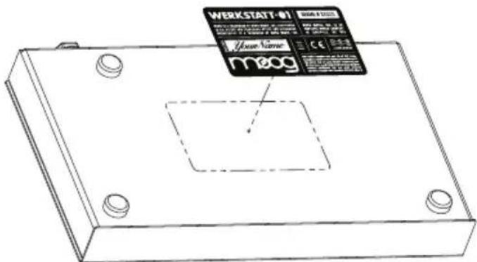
Lastly, peel the serial number label sticker from its backing paper and apply it to the back of your Werkstatt-01. You are now ready to write your name in the Built By section of the serial number label, connect the power supply, and begin exploring your new synthesizer!
YOUR WERKSTATT IS NOW COMPLETE.
Visit moogmusic.com/werkstatt for video assembly and calibration instructions.
A NOTE ABOUT 1V/OCTAVE
Your synthesizer and expander are calibrated to work together out of the box. Please note that in analog circuits, not all CV Outputs are designed the same. It is very possible that when the Werkstatt-01 Pitch CV input is calibrated to one source of a 1V/octave CV, it may respond slightly differently to a different source of 1V/octave CV, especially if that source is driving multiple loads, or if the source is not calibrated accurately. You can re-calibrate your Werkstatt-01 or the source of 1V/octave CV depending on the situation or your preference. Please visit www.moogmusic.com/werkstatt to download calibration instructions.
FEATURES AND CONTROLS
The Werkstatt is a monophonic (one note at a time) analog synthesizer, and as with many analog synthesizers, the Werkstatt is semi-modular in nature. While there are many hard-wired connections that allow the Werkstatt to be used as-is, the addition of a Patchable Header allows the freedom to connect the modules in new and creative ways.
DEFAULT SETTINGS
Carefully set all of the controls to the default positions shown below. This will provide a great starting point for exploring the functions and features of the Werkstatt-01 Analog Synthesizer.
![WERKSTATT-01 ANALOG SYNTHESIZER moog VCO FREQ WAVE PULSE SAW PWM VCF CUTOFF RES VCA ON EG MODE VCO MOD EG LFO AMOUNT PWM FREQ SOURCE AMOUNT DEST VCF MOD EG LFO AMOUNT [+] [-] POLARITY LFO RATE WAVE SQUARE TRIANGLE ENVELOPE ON OFF SUSTAIN ATTACK DECAY GLIDE](/content/2026/05/884420/images/69a8662a512e8945ac46f26d54f76bb52bbb57e48434fd4151853b4b8d228676.jpg)
VCO (VOLTAGE CONTROLLED OSCILLATOR)
The Oscillator is the primary sound generating component of an analog synthesizer. Based on the same circuitry as the Minimoog Voyager and Little Phatty, the Werkstatt oscillator produces a raw waveform that is rich in harmonics. While the keyboard determines the note being played, the frequency knob determines the pitch of that note.
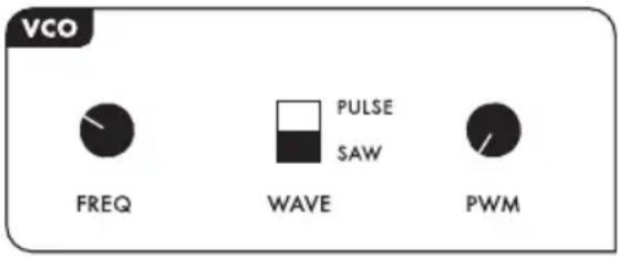
The keyboard determines the note played based on the setting of the Freq control - these two control inputs are summed together.
FREQ (FREQUENCY KNOB)
The Frequency knob offers a wide pitch range, extending over nine octaves. Keep in mind, the pitch is also controlled via the keyboard, and can be modified by other control signals. Depending on your monitoring system—and your ears—the outer ranges of the FREQ knob may appear to be inaudible.
Two waveform options are available on the Werkstatt. Each waveform, or wave-shape, carries a distinct harmonic content, creating a different sonic signature, known as timbre.
SAW: Short for Sawtooth, the Saw wave looks similar to the cutting edge of a saw blade. The Saw wave contains both even and odd numbered harmonics, and creates a bright and buzzy sound before filtering. The strength—or level—of each harmonic is the reciprocal of its number in the harmonic series.
PULSE: This waveform is unique in that it only contains the odd numbered harmonics. The ratio that controls the relative volume of these harmonics is determined by the Pulse Width. The width of the pulse can be anything from a wide rectangle to a square to a very narrow rectangle. The thinner the wave, the more the upper harmonics are accentuated.
PWM (PULSE WIDTH MODULATION)
When the Pulse waveform is selected, the Pulse Width Modulation knob can be used to determine the shape of the Pulse, thereby changing the timbre of the wave. With the knob set just a little left of center, the wave will be square, with a 50% duty cycle. The duty cycle is commonly thought of as the positive portion of the wave. The range of this knob can create a narrow pulse wave with a duty-cycle of almost zero, all the way up to a wide rectangular wave having about a 95% duty cycle.
NOTE: This knob will not function when the VCO MOD DEST switch is set to PWM. In this case, the Pulse Width will be controlled by the VCO MOD SOURCE.
VCF (VOLTAGE CONTROLLED FILTER)
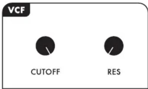
The Werkstatt uses the classic 24dB per octave Moog Ladder filter. This low-pass Voltage Controlled Filter (VCF) selectively shapes the timbre of the sound created by the oscillator, by attenuating and/or emphasizing certain harmonic elements.
CUTOFF (CUTOFF FREQUENCY KNOB)
The Cutoff knob specifies the frequency where the Filter is applied. Turning the knob to the right will open the filter, allowing more harmonic content to be heard, creating a brighter sound. Turning the knob to the left will close the filter, causing more harmonic content to be filtered, creating a darker sound.
RES (RESONANCE KNOB)
Directing the output of the filter back to the input allows the Moog filter to create a harmonic boost at the cutoff frequency. The amount of this boost, or emphasis, is controlled by the Resonance knob. By increasing the Resonance and decreasing the cutoff, the Werkstatt filter can be made to self-oscillate, creating a sine wave that can be used as second audio sound source.
VCA (VOLTAGE CONTROLLED AMPLIFIER)
This section controls the output level of the Werkstatt. As you may have noticed, there is no Volume knob on the Werkstatt. The VCA boosts the final audio signal to a suitable level.
MODE (MODE SWITCH)
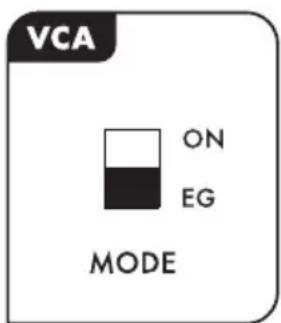
The VCA can function in one of two ways, controlled by the Mode switch.
ON: In this position, the VCA is always on, and the audio signal of the Werkstatt is output continuously, all the time. This setting is great for when you are creating synthesizer sounds and effects that need to play for an extended period, or droning sounds.
EG: EG is short for Envelope Generator. When the switch is in this position, the VCA is controlled by the Attack, Sustain, and Decay characteristics of the Envelope Generator Module.
VCO MOD (MODULATION OF THE VOLTAGE CONTROLLED OSCILLATOR)
Modulation is a way of introducing subtle or drastic changes to a sound—or anything in between. In order to use modulation effectively, you will need to select a modulation source, choose a destination, and control the depth of the effect.
VCO MOD

EG
LFO
SOURCE

AMOUNT

DEST
PWM
FREQ
SOURCE (SOURCE SWITCH)
This switch allows you to choose which Modulation Source will be applied to the Oscillator.
EG: EG is short for Envelope Generator. When the switch is in this position, the Attack, Sustain, and Decay characteristics of the Envelope Generator will be used as the modulation source.
LFO: LFO is short for Low Frequency Oscillator. The LFO produces a cyclic change that can be used to create a repeating effect. When the switch is in this position, the LFO will be used as the modulation source.
AMOUNT (AMOUNT KNOB)
Once a modulation source has been selected, the Amount knob can be used to control the depth of the modulation effect.
DEST (DESTINATION SWITCH)
This switch allows you to choose which control will be affected by the chosen Modulation Source.
PWM: When the switch is in this position, the Modulation source will be used to continually vary the width of the Pulse wave. The VCO Wave switch must be set to Pulse.
NOTE: Placing the switch in the PWM position will override the Pulse Width Modulation (PWM) knob in the VCO section.
FREQ: When the switch is in this position, the Modulation source will be used to continually vary the pitch of the Oscillator. This can be used to create a gentle vibrato or wild swoops in pitch, all depending on the Amount Knob and the setting of the LFO Rate knob (or EG).
VCF MOD (MODULATION OF THE VOLTAGE CONTROLLED FILTER)
Filter Modulation changes the value of the Filter's Cutoff Frequency. Either the EG or the LFO can be used as a Filter modulation source. When the EG is chosen as the modulation source, the polarity of the EG can be reversed for even greater sound creation options.
![VCF MOD EG LFO SOURCE AMOUNT POLARITY [+] [-]](/content/2026/05/884420/images/dbec0a05424ebe2fa08eaba610c692c26867023bb0d7e6cba001500c81778d6c.jpg)
SOURCE (SOURCE SWITCH)
This switch allows you to choose which Modulation Source will be applied to the filter.
EG: EG is short for Envelope Generator. When the switch is in this position, the Attack, Sustain, and Decay characteristics of the Envelope Generator will be used as the modulation source.
LFO: LFO is short for Low Frequency Oscillator. The LFO produces a cyclic change that can be used to create a repeating effect. When the switch is in this position, the LFO will be used as the modulation source.
AMOUNT (AMOUNT KNOB)
Once a modulation source has been selected, the Amount knob can be used to control the depth of the modulation effect.
POLARITY (POLARITY SWITCH)
The Polarity of the VCF modulation source can be reversed. That is, the normally negative portions will become positive, and vice-versa. For example, instead of using the Attack portion of the EG to boost the Filter Cutoff frequency, inverting the polarity will allow the Attack portion to lower the Filter Cutoff Frequency. Just be aware that if the Cutoff is already set low, inverting the EG polarity might close the Filter too far, making it appear as if the Werkstatt is not creating any sound.
[ + ]: Positive is the normal polarity for the VCF Modulation Source.
[-]: The negative position reverses the VCF Modulation Source.
LFO MOD (LOW FREQUENCY OSCILLATOR)
The Low Frequency Oscillator creates a consistent modulation source that can be used to add a repeating, cyclical change to any of the modulation sources. It can be used to modulate the Filter Cutoff Frequency, the Pitch of the Oscillator, or the Width of a Pulse wave. Using the Patchable Header, you can also use the LFO to modulate other parameters, such as the VCA output level. The Werkstatt LFO has an upper frequency of around 600 Hz—well within the audio range. This ability allows the LFO to create rich and unusual sounds when modulating the Oscillator pitch or other destinations.
RATE (RATE KNOB)
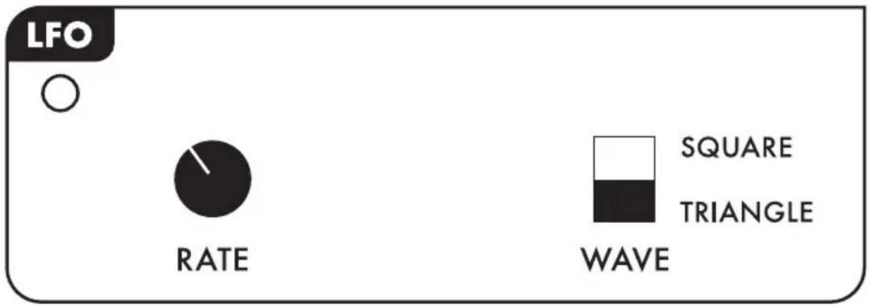
The speed, or frequency, of the LFO is controlled via this knob. The red LED will flash once for every wave cycle, providing visual feedback of the LFO speed.
WAVE (WAVE SWITCH)
This switch allows you to select the Waveform of the LFO.
SQUARE: When the Square wave is selected, the LFO will alternate between two distinct values representing the upper and lower limits of the wave. Some good examples of Square wave modulation are the emulation of an acoustic instrument playing a trill, or many vintage video game sounds.
TRIANGLE: The Triangle wave creates a continuously changing value that sweeps between the upper and lower limits of the wave. Vibrato is a good example of Triangle wave modulation.
ENVELOPE (ENVELOPE GENERATOR)
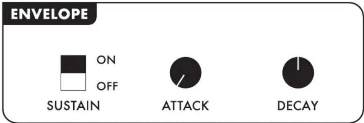
Each time a key is pressed or a trigger received, the Envelope Generator can produce a series of control voltages that allow you to change the value of certain parameters over time. The Attack, Sustain, and Decay parameters combine to create an Envelope shape that can be chosen as a modulation source.
SUSTAIN (SUSTAIN SWITCH)
In a simple sense, the Sustain switch allows you to choose either a piano-like behavior, or something more like an organ, by activating the Sustain segment of the Envelope Generator.
ON: When the Sustain switch is set to On, the Envelope will continue to sustain as long as the keyboard key is being played. In this mode, the Werkstatt behaves more like an organ.
OFF: The Off position bypasses the sustain segment of the envelope generator. The Envelope will advance directly from the Attack stage to the Decay stage. In this mode, the Werkstatt creates more of a plucked sound, like a piano.
NOTE: With the SUSTAIN switch in the OFF position, the attack must be very short or the EG will not produce an output.
ATTACK (ATTACK KNOB)
The time it takes for the Envelope Generator to reach its maximum level is known as the Attack time. For a fast Attack, turn this knob counter-clockwise. For a slower Attack, increase the value by turning the knob clockwise.
NOTE: Keep this knob turned down when the SUSTAIN switch in the OFF position, or the EG will not produce an output.
DECAY (DECAY KNOB)
The time it takes for the Envelope Generator to reach its lowest level after the key is released, or after the attack segment is complete is known as the Decay time. For a fast Decay, turn this knob counter-clockwise. For a slower Decay, increase the value by turning the knob clockwise.
KBD (KEYBOARD)
The Werkstatt is equipped with a one-octave, C to C keyboard. The keyboard features round buttons as opposed to traditional keys, but the layout is the same. The keyboard operates with a low note priority; if more than one note is played at the same time, the lowest note will sound.
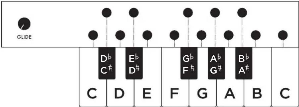
This diagram shows how the “button” keyboard of the Werkstatt (above) relates to a standard piano keyboard. Although the note names shown are correct for this layout, the actual note being produced will also depend on many factors, including the VCO FREQ knob, etc...
KEYBOARD OCTAVE SCALING
Play the lowest note [ C ] on the keyboard; now play the highest note [ C1 ]. The interval you hear between these notes should be one octave. If you have an electronic guitar tuner, you can use it to verify the notes being played. If the interval is not one octave, there is a Variable Resistor trimmer [ VR10 ] on the Printed Circuit Board labeled KB TRIM that can be adjusted to finetune the keyboard octave setting.
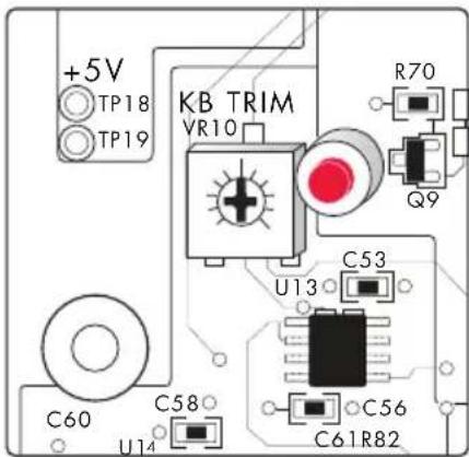
To perform the Keyboard Octave Scaling Calibration, press the lowest key on the keyboard and use the FREQ knob (VR1 VCO PITCH) to tune the Werkstatt to produce a C on your tuner. Next, press the highest key on the Werkstatt keyboard and gently turn KB TRIM VR10 until your tuner reads a C one octave higher.
For a video walk-through of this and other Werkstatt calibrations, please visit www.moogmusic.com/werkstatt
GLIDE (GLIDE KNOB)
To achieve a smooth pitch transition from one note to another, increase the Glide amount. Turning the knob clockwise increases the amount of time required to glide from one note to another. Turning the knob counter-clockwise will cancel the glide effect.
PATCH (PATCHABLE HEADER)
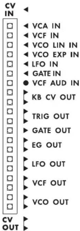
Unlike fully modular analog synthesizers that have patch points on every module, the Werkstatt has gathered these inputs and outputs into a single compact Patchable Header.
The physical format is different, but the function is the same. The Patchable Header allows control signals generated by the Werkstatt to be easily routed to the control inputs of the VCO, VCF, VCA, and LFO, vastly expanding the sound creation possibilities of the synthesizer. The five patchable header cables included with the Werkstatt are designed to make the most of these patch points. In addition to control signal inputs, the Patchable Header also features an audio input that feeds directly into Werkstatt-01's analog filter for the processing of external audio signals.
NOTE: By connecting the Werkstatt-01 CV Expander, 12 of the most useful inputs from the Patchable Header are broken out as 3.5mm jacks suitable for connecting to external synth gear via standard 3.5mm patch cables.
BEST PRACTICES
In general, the Werkstatt is designed so there are no “illegal” patches, though not all make musical sense. In experimenting with the Patchable Header, there are some ground rules/best practices that apply.
It is common to create a "Y" connection at a CV out point and drive two separate inputs. Many of the Werkstatt's outputs already have two connections. However, it is best to avoid mixing two Control signals by creating a "Y" connection at a CV input, as adding these voltages together can possibly exceed the capabilities of the input. You should also avoid patching an output to an output; this is another version of passive voltage summing that can lead to unpredictable results. Patching an input to an input is not likely to result in any useful response.
Note that there are control outputs for both the VCO and VCF signals. Technically, these are audio outputs; these audio outputs can serve double duty as control signals. For example, the VCO output can be used for audio rate modulation, or it can go down to 8 Hz—low enough to use as a LFO.
PATCHING WITH OTHER ANALOG INSTRUMENTS
The Patchable Header was not designed to connect with external CV gear, but it is possible. For more information and cautions, please refer to the Interfacing with Other Synthesizers and Effects section of this manual.
REAR PANEL
The Werkstatt's rear panel features two connection points; one audio output, and one power jack.
AUDIO OUTPUT
The Werkstatt's single audio output features a 1/4" unbalanced (TS) jack.
POWER INPUT
Use only the DC power supply that was provided to power your Werkstatt. Plug the connector end into the Werkstatt, and plug the other end into a compatible wall outlet.
ABOVE AND BEYOND
For some, the Werkstatt is simply a starting point for exploring new sonic possibilities. It is possible to modify the internal circuitry, and to interface with other music-making devices. Here are a few guidelines to get you started.
INTERFACING WITH OTHER SYNTHESIZERS AND EFFECTS
COMMON GROUND
If you elect to use Werkstatt-01 without the CV Expander, please note that the Patchable Header wasn't specifically designed to connect with external CV gear, but it is possible to do so. If a CV connection between an external piece of CV gear and the Werkstatt is desired, the two devices must share a common ground connection or the external control will not work. The simplest way to achieve this is to plug the two devices into the same audio mixer. Both devices will have ground at the sleeve of their audio jacks. Make this audio/ground connection before connecting the units together.
USE CAUTION
Patching to external CV and Audio sources can subject the Werkstatt to voltages and currents that are beyond what it was designed to withstand. Caution should be exercised when selecting gear that will connect to the Werkstatt. Verify that the equipment used to provide a common ground connection is not faulty. Refer to the Specifications section for acceptable voltages.
CALIBRATING THE WERKSTATT FOR 1 VOLT PER OCTAVE
The VCO EXP IN connection point on the Patchable Header (also available as 3.5mm jack by connecting the CV Expander) can be set to receive one-volt-per-octave control signals. This calibration is performed using the Variable Resistor trim pot [VR5] labeled VCO EXP TRIM. It is located on the Printed Circuit Board, below and to the right of the VCO Pitch potentiometer.
To calibrate, connect an instrument tuner to the 1/4" output of your Werkstatt-01 and patch the pitch output of an external CV controller to the VCO EXP FM IN jack on the Werkstatt-01.
NOTE: if using the 3.5mm CV Expander, you must connect the screws at the top and bottom of the CV Expander to ground the device for accurate calibration. Visit www.moogmusic.com/werkstatt for a detailed video walkthru of this and other Werkstatt-01 calibrations.
Next, press the lowest note on the Werkstatt-01 keyboard, and set the VCO FREQ knob slightly right of center position until the tuner reads Middle C. Using an external CV controller, alternate playing the note C across a three octave range. Adjust VR5 until your instrument tuner reads a C note consistently across all three octaves. Repeat this process to verify calibration accuracy.
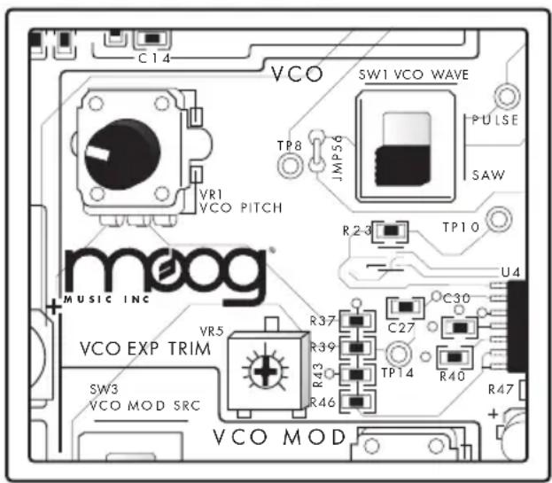
Note that on the Patchable Header, the KB CV is output as about 0.3 Volts/semitone, which is equivalent to about 3.6 Volts/Octave. This allows the use of the Keyboard as a wider range controller than if it were output as 1 Volt/Octave.
STUDYING THE WERKSTATT'S ANALOG CIRCUITS
The Werkstatt circuitry was designed to invite exploration and study of its analog circuits. The complete schematic for the Werkstatt Printed Circuit Board can be downloaded from the Moog Music Website: www.moogmusic.com/werkstatt.
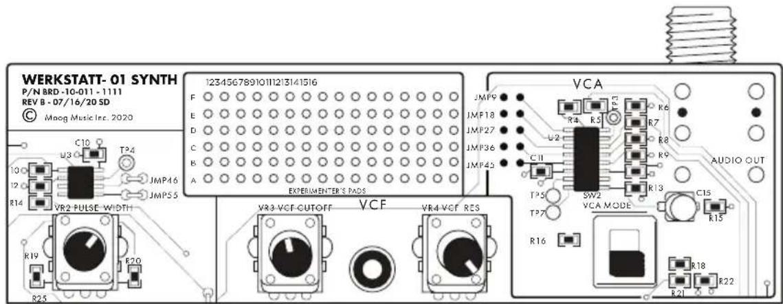
Test Points, Jumpers, and a mini 16 x 6 Experimenter's pad are provided on the Werkstatt Printed Circuit Board. Although the Printed Circuit Board was created using Surface Mount Design, these features use plated through-hole construction to make measuring and experimenting easier.
TEST POINTS (TP)
Plated through-hole test points are provided, allowing the ability to breakout the most important signals. In some cases, Test points have been added to control nodes for studying the behavior of the outputs of the circuits.
JUMPERS (JMP)
Plated through-hole jumpers exist for certain Audio Signal and Control Signals. Jumpers also exist for the unused Integrated Circuit pins (IC Gates) in order to terminate the unused inputs.
EXPERIMENTER'S BREADBOARD PADS
This 16 x 6 grid of unconnected through-hole pads provides an area for bread-boarding new circuit designs. On the schematic these appear as a group of unconnected jumpers.
WARRANTY WARNING
Hacking or modifying your Werkstatt in any way will naturally void your warranty, as Moog Music cannot warrant parts and labor outside the original configuration of the product.
In addition, please note that any changes or modifications made to this product could void the user's authority granted by the FCC to operate the equipment. Moog Music Inc. does not recommend the modification of this product.
SCHEMATIC DOWNLOAD AGREEMENT
BY DOWNLOADING THE WERKSTATT SCHEMATIC, YOU ARE AGREEING TO THE FOLLOWING TERMS:
- All copyrights to the circuit diagrams for the Werkstatt are the property of MOOG MUSIC INC. Copying this content in part or in whole without the permission of the copyright owner is forbidden by copyright law. However, you are permitted to make a single copy for personal non-commercial purposes.
- You are expressly forbidden to engage in commercial activities such as selling the circuit diagram materials that you have copied in part or in whole.
- The circuit diagrams are provided for customers who have purchased the product, and the reader is assumed to be a user of the product. Please be aware that in some cases, MOOG MUSIC INC., its authorized dealers, and distributors may be unable to respond to inquiries regarding published circuit diagram materials from people who have not purchased the product.
- Specifications and electronic circuits of products are subject to change without notice.
- MOOG MUSIC INC. does not recommend modification of its products.
- Please be aware that modifying any Moog Music product will void the warranty.
- MOOG MUSIC INC., its authorized dealers, and the distributors shall bear no liability for any damages (loss of business profits or data, financial loss, or impairment of health) resulting from your use of these circuit diagrams. This limitation of liability shall apply even if MOOG MUSIC INC., its authorized dealers, and the distributors had been informed beforehand of the possibility of such damages.
- Please be aware that this downloading service may be terminated or modified without notice.
SPECIFICATIONS
All Specifications subject to change without notice.
SOUND SOURCE:
VCO - VOLTAGE CONTROLLED OSCILLATOR
Range: 0 to +5 Volt Signal; 8Hz \~ 16KHz from KB and VCO Freq Control
CONTROLLERS:
Waveform Switch: Saw or Pulse
PWM Knob: Pulse Width Modulation
FREQ Knob: Sweeps VCO over 8 Octaves
CONTROL INPUTS:
KB CV: 1 Octave; with Glide
VCO MOD: Selectable LFO/EG Switch; Assignable Pitch or PWM
VCO EXP IN: Exponential FM Input - 1 Volt/Octave nominal, trimmable via VR 5
VCO LIN IN: Linear FM Input - this is an inverted input (increase in voltage applied lowers the frequency)
CONTROL OUTPUTS:
VCO CV: Control Voltage / Audio Output
SOUND MODIFIERS:
VCF - VOLTAGE CONTROLLED FILTER
Type: 4-pole (24 dB/Octave), Ladder; self-oscillating low-pass filter with resonance
CONTROLLERS:
CUTOFF knob: Selectable LFO/EG Switch; Polarity Switch
VCF IN: Filter Cutoff Input
CONTROL INPUTS:
VCF MOD: Selectable LFO/EG Switch; Polarity Switch
VCF IN: Filter Cutoff Input
CONTROL OUTPUTS:
VCF Output: ±2 Volt Signal usable as CV or Sound Source
VCA - VOLTAGE CONTROLLED AMPLIFIER
CONTROLLERS:
MODE switch: EG / ON
CONTROL INPUTS:
VCA IN: Control Voltage Input
MODULATION SOURCES:
LFO - LOW FREQUENCY OSCILLATOR
Range: ± 2.5 Volt
CONTROLLERS:
RATE knob: Modulation Frequency (.2 Hz \~ 600 Hz)
WAVE switch: Triangle / Square
CONTROL INPUTS:
LFO IN: LFO Rate Control Voltage
CONTROL OUTPUTS:
LFO OUT: LFO Rate Control Voltage
EG - ENVELOPE GENERATOR
Range: 0 to +5 Volt
CONTROLLERS:
ATTACK knob: Attack Time
DECAY knob: Decay Time
SUSTAIN switch: Sustain Level ON / OFF
CONTROL OUTPUTS:
EG OUT: Envelope Control Voltage
KBD - KEYBOARD
Type: 13 keys (1 Octave); Low-Note Priority; Legato Triggering with Glide
CONTROLLERS:
GLIDE knob: Time of Glide (Portamento) effect
CONTROL INPUTS:
GATE: Keyboard Gate Input; 0 \~ +5 Volt signal
CONTROL OUTPUTS:
KB CV OUT: Keyboard Control Voltage Output;
3.7 Volts per Octave, nominal level
TRIG: Keyboard Trigger Output; 5 msec pulse;
0 - +5 Volt signal
GATE: Keyboard Gate Output; 0 \~ +5 Volt signal
PATCHABLE HEADER
CONTROL VOLTAGE INPUTS:
VCA IN: 0 to +5 Volt (VCA MODE switch set to ON) -2.5 to +2.5 Volt (VCA MODE switch set to EG)
VCF IN: -5 to +5 Volt (Cutoff Frequency)
VCO LIN IN: Linear Pitch Input; 3 2.5 Volt (Inverting control input)
VCO EXP IN: Exponential Pitch Input; -5 \~ +5 Volt, 1V/Octave, trimmable
LFO IN: -5 to +5 Volt (Negative CV slows LFO further than available on panel)
GATE IN: 0V (off) to +5V (on) gate signal to trigger EG
AUDIO INPUTS:
VCF AUD IN: Filter Audio Input (Un-buffered/Un-mixed AC coupled)
CONTROL VOLTAGE OUTPUTS:
KB CV OUT (x2): Nominal 0.3V/semitone from 1 octave keyboard (Note: Attenuate for 1 V/Octave)
TRIG OUT (x2): 5 msec, 0 to +5 Volt pulse from keyboard GATE OUT (x1): 0V (off) to +5 Volt (on) gate signal from keyboard EG Output (x2): ASD / AD type Envelope Generator, 0 to +5V signal
LFO Output (x2): -2.5 to +2.5 Volt Triangle or Square wave; Shape selected by LFO WAVE switch
VCF Output (x2): -2 to +2 Volt signal for audio or CV uses.
VCO Output (x2): 0 to +5 Volt VCO signal; Shape selected by VCO WAVE switch
AUDIO OUTPUT:
1/4" Unbalanced Output; Nominal 3 1.5 Volt Signal
POWER:
AC wall transformer
Output: +12 Volts DC; 1.2 Amperes; 2.1mm Center Pin Positive
Input: 100 to 240VAC, 50 to 60 Hz; Typical power consumption - 2 Watts
natural_image
Illustration of a screwdriver with a flathead end (no text or symbols)WARRANTY AND SERVICE INFO
INSIDE THE USA
WHAT IS MOOG'S STANDARD DOMESTIC WARRANTY?
Moog warrants its products to be free of defects in materials or workmanship and conforming to specifications at the time of shipment.
Inside the USA, the Warranty Period is one year from the date of purchase. If, in Moog's determination, it has been more than five years since the product shipped from our factory, it will be at Moog's discretion whether or not to honor the warranty without regard to the date of the purchase. During the Warranty Period, any defective products will be repaired or replaced, at Moog's option, on a return-to-factory basis. This warranty covers defects that Moog determines are no fault of the user.
If you have questions regarding your domestic warranty, please contact techsupport@moogmusic.com
HOW TO INITIATE YOUR WARRANTY.
Please initiate your warranty online at www.moogmusic.com/register. If you do not have web access, please call (828) 251-0090 to register your product.
HOW TO RETURN YOUR INSTRUMENT FOR SERVICE.
Customer is responsible for all shipping and freight charges to transport product to Moog's specified authorized service center. An RMA or return merchandise authorization is required and can be requested by contacting techsupport@moogmsuic.com. Include serial number, description of the problem, and full contact information. All products must be packed carefully and shipped with the Moog supplied power adapter. Your instrument must be returned in the original inner packing including the cardboard inserts. The warranty will not be honored if the product sustains damage from being improperly packed. Once you have received the RMA# and carefully packed your Moog, ship the product to Moog's Authorized Service Center with transportation and insurance charges paid, and be sure to include your return shipping address.
WHAT WE WILL DO
Once received, we will examine the product for any obvious signs of user abuse or damage as a result of transport. If the product abused, damaged in transit, or is out of warranty, we will contact you with an estimate of the repair cost. Warranty work will be performed, and Moog will ship and insure your product to your United States address free of charge.
WARRANTY AND SERVICE INFO OUTSIDE THE USA
WHAT IS MOOG'S STANDARD INTERNATIONAL WARRANTY?
Moog warrants its products to be free of defects in materials or workmanship and conforming to specifications at the time of shipment.
Outside the USA the warranty policy and associated service is determined by the laws of the country of purchase and supported by our local authorized distributors. A listing of our authorized distributors is available at moogmusic.com. Please feel free to reach out to them or the retailer from whom you purchased your instrument for support.
If you have questions regarding your international warranty, please contact techsupport@moogmusic.com
HOW TO INITIATE YOUR WARRANTY
Please initiate your warranty online at www.moogmusic.com/register. If you do not have web access, please call (828) 251-0090 to register your product.
HOW TO RETURN YOUR INSTRUMENT FOR SERVICE.
Outside the USA, service is determined by the laws of the country of purchase and supported by our local authorized distributors. Please reach out to them or the retailer from whom you purchased your instrument for service support.
If you have questions regarding your international service, please contact techsupport@moogmusic.com
natural_image
Illustration of a screwdriver with a pointed tip and hexagonal head (no text or symbols)Note: Specifications subject to change without notice.
Moog®, and Werkstatt-01® are registered trademarks of Moog Music Inc.
©2020 Moog Music Inc.
MOOG MUSIC INC. 160 Broadway St., Asheville, NC 28801
P: (828) 251-0090 E: info@moogmusic.com W: www.moogmusic.com
- WERKSTATT-01
- IMPORTANT SAFETY INSTRUCTIONS
- WARNING - WHEN USING ELECTRIC PRODUCTS, THESE BASIC PRECAUTIONS SHOULD ALWAYS BE FOLLOWED.
- NOTE:
- TABLE OF CONTENTS
- ASSEMB LY
- WERKSTATT FEATURES AND CONTROLS
- ABOVE AND BEYOND
- ANALOG SYNTHESIZER BASICS
- ASSEM B LY
- A NOTE ABOUT ELECTROSTATIC DISCHARGE:
- PARTS LIST
- ASSEMBLY INSTRUCTIONS
- 1) ATTACHING THE FEET
- 2) ATTACHING THE WASHER
- 3) INSTALLING THE ELECTRONICS
- 4) POWER / LED TEST
- 5) ATTACHING KEYBOARD BUTTONS
- 6) ADDING THE TOP PANEL
- 7) ATTACHING THE CV EXPANDER
- 8) APPLYING THE SERIAL NUMBER LABEL
- YOUR WERKSTATT IS NOW COMPLETE.
- A NOTE ABOUT 1V/OCTAVE
- FEATURES AND CONTROLS
- DEFAULT SETTINGS
- VCO (VOLTAGE CONTROLLED OSCILLATOR)
- FREQ (FREQUENCY KNOB)
- PWM (PULSE WIDTH MODULATION)
- VCF (VOLTAGE CONTROLLED FILTER)
- CUTOFF (CUTOFF FREQUENCY KNOB)
- RES (RESONANCE KNOB)
- VCA (VOLTAGE CONTROLLED AMPLIFIER)
- MODE (MODE SWITCH)
- VCO MOD (MODULATION OF THE VOLTAGE CONTROLLED OSCILLATOR)
- VCO MOD
- SOURCE (SOURCE SWITCH)
- AMOUNT (AMOUNT KNOB)
- DEST (DESTINATION SWITCH)
- VCF MOD (MODULATION OF THE VOLTAGE CONTROLLED FILTER)
- POLARITY (POLARITY SWITCH)
- LFO MOD (LOW FREQUENCY OSCILLATOR)
- RATE (RATE KNOB)
- WAVE (WAVE SWITCH)
- ENVELOPE (ENVELOPE GENERATOR)
- SUSTAIN (SUSTAIN SWITCH)
- ATTACK (ATTACK KNOB)
- DECAY (DECAY KNOB)
- KBD (KEYBOARD)
- KEYBOARD OCTAVE SCALING
- GLIDE (GLIDE KNOB)
- PATCH (PATCHABLE HEADER)
- BEST PRACTICES
- PATCHING WITH OTHER ANALOG INSTRUMENTS
- REAR PANEL
- AUDIO OUTPUT
- POWER INPUT
- INTERFACING WITH OTHER SYNTHESIZERS AND EFFECTS
- COMMON GROUND
- USE CAUTION
- CALIBRATING THE WERKSTATT FOR 1 VOLT PER OCTAVE
- STUDYING THE WERKSTATT'S ANALOG CIRCUITS
- TEST POINTS (TP)
- JUMPERS (JMP)
- EXPERIMENTER'S BREADBOARD PADS
- WARRANTY WARNING
- SCHEMATIC DOWNLOAD AGREEMENT
- BY DOWNLOADING THE WERKSTATT SCHEMATIC, YOU ARE AGREEING TO THE FOLLOWING TERMS:
- SPECIFICATIONS
- SOUND SOURCE:
- VCO - VOLTAGE CONTROLLED OSCILLATOR
- CONTROLLERS:
- CONTROL INPUTS:
- CONTROL OUTPUTS:
- SOUND MODIFIERS:
- VCF - VOLTAGE CONTROLLED FILTER
- VCA - VOLTAGE CONTROLLED AMPLIFIER
- MODULATION SOURCES:
- LFO - LOW FREQUENCY OSCILLATOR
- EG - ENVELOPE GENERATOR
- KBD - KEYBOARD
- PATCHABLE HEADER
- CONTROL VOLTAGE INPUTS:
- AUDIO INPUTS:
- CONTROL VOLTAGE OUTPUTS:
- AUDIO OUTPUT:
- POWER:
- AC wall transformer
- WARRANTY AND SERVICE INFO
- INSIDE THE USA
- WHAT IS MOOG'S STANDARD DOMESTIC WARRANTY?
- HOW TO INITIATE YOUR WARRANTY.
- HOW TO RETURN YOUR INSTRUMENT FOR SERVICE.
- WHAT WE WILL DO
- WARRANTY AND SERVICE INFO OUTSIDE THE USA
- HOW TO INITIATE YOUR WARRANTY
Brand : Moog
Model : Werkstatt-01
Category : Synthesizer