
KIPICT555 - Mounting bracket Peerless-AV - Free user manual and instructions
Find the device manual for free KIPICT555 Peerless-AV in PDF.

| Product Type | Interactive Kiosk (Mounting Bracket Category) |
| Screen Size | 55" |
| Resolution | 1920 x 1080 |
| Brightness | 450 nits |
| Contrast Ratio | 1100:1 |
| Viewing Angle | 178° x 178° |
| Response Time | 12 ms |
| Refresh Rate | 60 Hz |
| Life Expectancy | 50,000 hours |
| Speakers | 2 x 10W |
| Product Dimensions (W x H x D) | 75" x 33" x 3" (1907mm x 827mm x 79.5mm) |
| Package Dimensions (W x H x D) | 89" x 40" x 23" (2255mm x 1004mm x 572mm) |
| Net Weight | 211.6 lbs (96 kg) |
| Gross Weight | 260.14 lbs (118 kg) |
| Operating Temperature | 32°F to 104°F (0°C to 40°C) |
| Storage Temperature | -14°F to 140°F (-10°C to 60°C) |
| Power Input | 100-240V AC, 50-60Hz, 5A |
| Power Consumption | 73W max |
| Connectivity | Wi-Fi/Bluetooth (M.2), Ethernet (RJ45), USB 2.0 x2, GPIO, RS-232, IR In/Out, microSD slot, 3.5mm audio |
| Included Accessories | Remote control (AAA batteries), power cords (US, UK, EU), Wi-Fi antenna |
| Safety Features | GFCI outlet requirement, ground connection, surge protection advised, no user-serviceable parts, keep away from heat/moisture |
Frequently Asked Questions - KIPICT555 Peerless-AV
User questions about KIPICT555 Peerless-AV
0 question about this device. Answer the ones you know or ask your own.
Ask a new question about this device
Download the instructions for your Mounting bracket in PDF format for free! Find your manual KIPICT555 - Peerless-AV and take your electronic device back in hand. On this page are published all the documents necessary for the use of your device. KIPICT555 by Peerless-AV.
USER MANUAL KIPICT555 Peerless-AV
natural_image
Line drawing of a rectangular electronic device with a flat top and base (no text or symbols)WARNING
RISK OF ELECTRICAL SHOCK
To reduce the risk of electric shock, do not disassemble the unit under any circumstances. No user serviceable parts inside. All product services should be done by the Peerless-AV certified service personnel.
Read before operating equipment
Thank you for purchasing our product. Before using it, please read this user manual carefully and follow the instructions correctly for safe operation. Please keep this manual handy for future reference. Also, please be sure to always include this user manual in the packaging when transferring or transporting this product to a different location.
Batteries Installed Warning
CAUTION - Danger of explosion if batteries are incorrectly replaced. Replace only with the same or equivalent type. Even though the remote is designed for outdoor usage, the batteries should not be exposed to excessive heat due to sunlight, fire or other heat sources.
CAUTION:
To reduce the risk of electric shock, do not perform any servicing other than that contained in the operating instructions unless you are qualified to do so.
- These kiosks are heavy and should be moved and installed by at least two individuals. Do not attempt to move or install the kiosk yourself, otherwise injury and/or damage may occur. When moving the kiosk, always hold the kiosk firmly.
- When moving kiosk carton, do not tilt or invert the carton. Always keep it in an upright position.
- Disconnect all accessories and cables before moving the display.
- Refer to this guide for proper startup and shutdown procedures.
- Follow all warnings and cautions in this manual and on the kiosk.
- Locate the kiosk at least 4 feet away from heating and cooling vents.
- Do not block ventilation openings. Locate the kiosk in a well-ventilated area without obstructions to intake or exhaust vents.
- Do not install or use the kiosk near any heat sources such as radiators, heat registers, stoves, or other devices (including amplifiers) that produce heat.
- Do not place kiosk in direct sunlight, humid, greasy or dusty places or in places where the kiosk may come into contact with rain, smoke or steam.
- The kiosk should not be used with the power cord near water, for instance, near a bathtub, washbowl, kitchen sink or swimming pool, etc.
- Do not use of the kiosk near water. Warning: To reduce the risk of fire or electric shock, do not expose this equipment to rain or moisture.
- Do not drop the display.
- Do not spill liquid on the display. Spilled liquid may damage the kiosk.
- Warning: It is recommended that this display is securely attached to floor per installation instructions. Tipping, shaking, or rocking the machine may cause injury or death.
- The power outlet used to power this kiosk should be readily accessible for fast disconnection in case of emergency.
- No flame source, such as lighted candles, should be placed on the display.
- Use the power cord provided. Connect the power cord to a receptacle with a protective safety (earth) ground terminal. A surge-protected power strip is recommended. Do not overload wall outlets.
- Do not install the display in places subject to mechanical vibration.
-
Do not place the display on an instable surface, which could result in serious personal injuries and kiosk damage.
-
When disconnecting the power cord, hold the plug, not the cord.
- Protect the power cord from being walked on or pinched particularly at plugs, convenience receptacles and the point where they exit from the display.
- Unplug the kiosk if you are not going to use it for an extensive period of time.
- Unplug the kiosk if you need to clean it with a microfiber cleaning cloth. The screen may be wiped with the cleaning cloth when the power is off. Never use alcohol, solvents or ammonia-based liquids on this kiosk.
- Wash hands after handling the cables supplied with this kiosk.
- The kiosk remote control uses batteries (included). Make sure the batteries' polarity (+/-) is aligned correctly. Dispose of used batteries in accordance with local disposal laws.
- Refer all servicing to qualified service personnel. Do not remove the cover or back. Servicing your own kiosk can be dangerous to you and will void the warranty.
- Store all small accessories and parts out of the reach of children.
- Follow these instructions to help ensure image quality over the life of the display. Failure to follow these instructions may affect the warranty.
- Do not defeat the safety purpose of the polarized or grounding type electrical plug. A polarized plug has two blades with one wider than the other. A grounding type plug has two blades and a third grounding prong. The wide blade or the third prong are provided for your safety. If the provided plug does not fit into your outlet, consult an electrician for replacement of the obsolete outlet.
- In case of emergency such as fire or electric shock caused by the product, immediately contact 911 or proper emergency police/fire service agencies in your country.
- If LCD or glass is broken, do not come in contact with the liquid crystal and handle with care.
- Use properly rated electrical voltage. Use of non-rated voltage may cause fire, electric shock and severe damages to the product.
- Do not open the cabinet under any circumstances. High voltage inside of this product may cause electric shock.
- Do NOT climb on the product.
- Do NOT, under any circumstances, modify or disassemble this product as it may cause fire, electric shock, or severe damages to the product. Also, any unauthorized modifications made to the product automatically void product warranty.
- Any severe physical impact on the product may cause certain components to fall out of place within and break, which may cause fire or electric shock. In such event, do not operate the product. Contact the manufacturer for support.
- Periodically clean dust off the electrical plug to keep it clean and dry, ensuring proper and safe operation of the product.
- Do NOT touch electrical plugs with wet hands.
- Always make sure to plug in the electrical plug firmly and completely. Incompletely placed electrical plugs may cause fire or electric shock due to built up heat emission.
- In case of product malfunction or unusual events such as electrical burning smell, smoke, or loss of content signals due to internal overheating, immediately turn off and unplug the electrical cord and contact the manufacturer.
- Do NOT move or transport the product with any cables (electrical cables, content connectivity cables) plugged in to the source devices. Damages may occur to the cables, plugs, or jointing connectors of the cables due to forcible bending and stress, which may cause damages to the waterproof seal of the product, making it subject to fire, electric shock, or shorted circuit.
- Always leave the Power Off when plugging or unplugging the electrical cords or connection cables to avoid electric shock or damages to the product.
- Do NOT use any chemical such as paint thinner or benzene to clean the product's exterior. It may cause scratches on the surface, erasing proper indications, identification labels, or instructions on the exterior, which may cause misuse and improper operation of the product.
FCC STATEMENT
This equipment has been tested and found to comply with the limits for a Class A digital device, pursuant to Part 15 of the FCC Rules. These limits are designed to provide reasonable protection against harmful interference in a commercial installation. This equipment generates, uses and can radiate radio frequency energy and, if not installed and used in accordance with these instructions, may cause harmful interference to radio communications; however, there is no guarantee that interference will not occur in a particular installation.
Operation of the equipment in a residential area is likely to cause harmful interference in which case the user will be required to correct the interference at his own expense. Changes or modification not expressly approved by Peerless-AV may void the authority to operate the equipment.
This device complies with Part 15 of the FCC Rules. Operation is subject to the following two conditions:
- This device may not cause harmful interference.
- This device must accept any interference received, including interference that may cause undesired operation.
Canada
This Class A digital apparatus complies with Canadian ICES-003. This device complies with part 15 of the FCC Rules / RSS-210. Operation is subject to the following two conditions:
- This device may not cause harmful interference.
- This device must accept any interference received, including interference that may cause undesired operation.
Relevant Information
Record your product's model and serial number here for future reference. Keep this user manual in an accessible location in the event service is required.
Note: Your kiosk's serial number can be found inside the lower cabinet on the label.
Model Number ____
Serial Number ____
SET UP INSTRUCTIONS
Parts List
Description Qty
A kiosk assembly 1
B BrightSign wi-fi antenna 1
C power cord (US) 1
D power cord (UK) 1
E power cord (EU) 1
F remote control 1
G AAA battery 2
A (1)
kiosk assembly

natural_image
Isometric line drawing of a rectangular electronic device with a flat top and base (no text or symbols)B (1)
BrightSign wifi antenna
natural_image
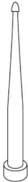
Simple line drawing of a conical object with a pointed tip and base (no text or symbols)F (1)
remote

G (2)
AAA battery

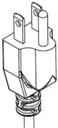
C (1)
power cord (US)
natural_image
Technical line drawing of a mechanical component with two protruding pins and a coiled spring (no text or symbols)D (1)
power cord (UK)
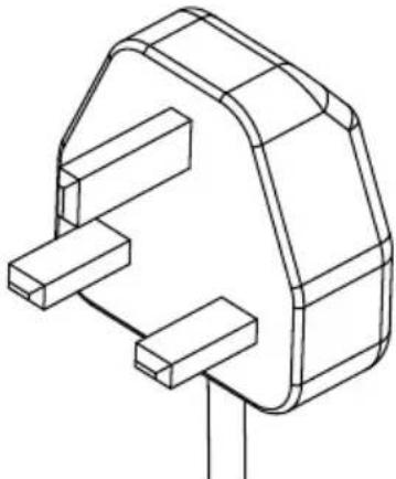
natural_image
Technical line drawing of a mechanical component with no visible text or symbolsE (1)
power cord (EU)
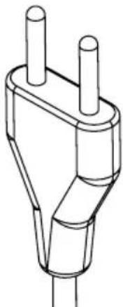
natural_image
Line drawing of a plug socket with two leads (no text or symbols)Connecting Cables
Connect cables from the source devices to their appropriate connector on the display.
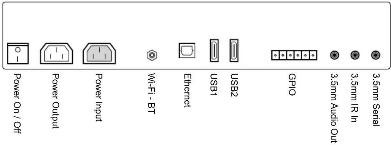

External Ethernet Extension
External USB 1 Extension
External USB 2 Extension
Power Source
The kiosk must be connected to a mains socket outlet with a protective grounding connection.
The mains plug is used as the disconnect device and shall remain readily accessible.
This display operates on 100-240 volts 50-60 Hz, AC current. Insert the power cord into a 120-220 volt 60 Hz outlet. Never connect the kiosk to direct current or anything other than the specified voltage. To prevent electric shock from the kiosk, do not use with an extension cord, receptacle, or other outlet unless the blades and ground terminal can be fully inserted to prevent blade exposure.
WARNING
- Never remove the back cover of the kiosk as this can expose you to very high voltages and other hazards. If the kiosk does not operate properly, unplug the kiosk and call your authorized dealer or service center.
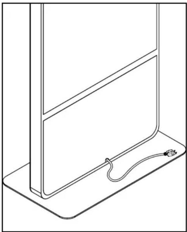
Connect To The Power Source
Connect power cord to GFCI outlet.
CAUTION
- Please use the electrical cord provided with this display. If a electrical cord is not supplied with this equipment, please contact your supplier. Only plug equipment into receptacles with GFCI protection.
- Peerless-AV is not responsible for any issues created by water present at the plug/receptacle insertion point.
natural_image
Line drawing of a simple electrical component with a cable and plug, no text or symbols present| Power | |
| Input rating | 100-240V, 50-60Hz, 5A |
| Output rating | 100-240V, 50-60Hz, 1A |
natural_image
Pure electrical circuit lines without any symbols
natural_image
Simple line drawing of a rectangular electrical socket with two vertical slots and four rectangular outlets (no text or symbols)Remote Control Battery Installation And Replacement
The remote control is powered by two 1.5V AAA batteries.
- To remove the battery cover of the remote control, pinch then pull off battery cover.
- Insert two new "AAA" size batteries into the battery module.
- Snap the battery cover back into the remote control.
CAUTION
Incorrect usage of batteries can result in leaks or bursting. Peerless-AV recommends the following battery use:
- Do not mix battery brands.
- Do not combine new and old batteries. This can shorten the battery life or cause liquid leakage of the batteries.
- Remove dead batteries immediately to prevent battery acid from leaking into the battery compartment.
- Do not touch exposed battery acid as it may injure skin.
- Remove the batteries if you do not intend to use the remote control for a long period of time.

Using The Remote Control
The buttons not specified below are reserved for future versions.
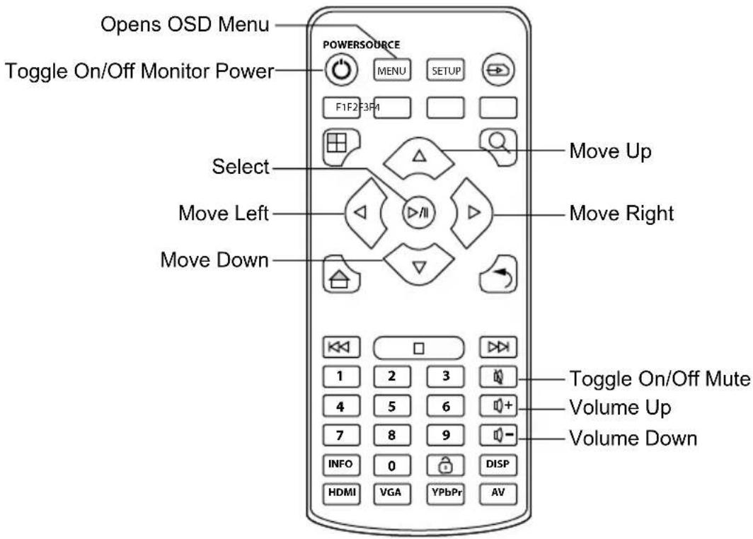
OPERATING INSTRUCTIONS
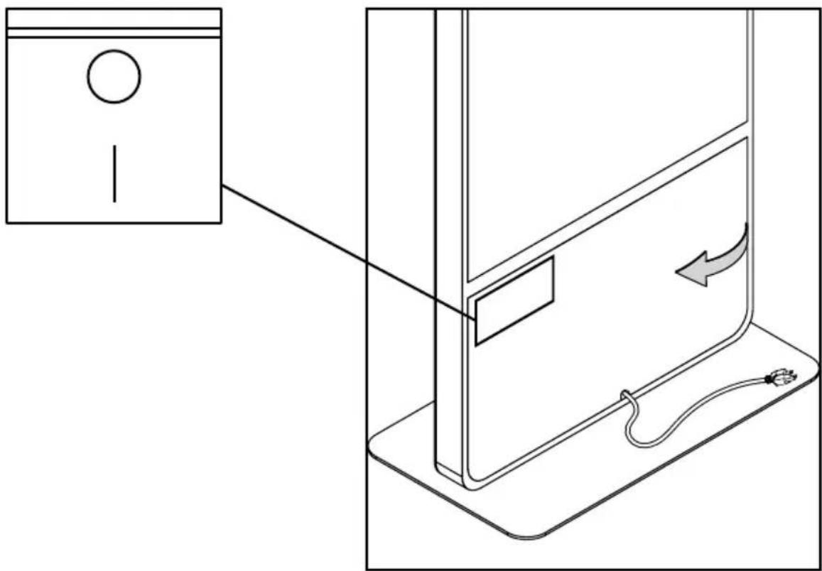
Power On/Off Your New Kiosk
Power on your Kiosk by flipping the power switch in the rear compartment, then pressing the power button on your remote control.
natural_image
Diagram of a device with a lock and cable, showing a close-up view of the front panel (no text or symbols)Getting Started
- Install BrightAuthor. BrightAuthor requires the latest version of Microsoft.Net Framework. If this component is not already on your PC, BrightAuthor installs it during the installation; however, if BrightAuthor needs to install Microsoft.Net framework. The installation may take up to 45 minutes to complete, and you may need to restart your PC to complete installation.
a. Go to the BrightSign downloads page: https://www.brightsign.biz/downloads/overview
b. Locate the model series BrightSign DSM of your player and click on More Downloads.
c. Select the Official Release or Beta Release of BrightAuthor software for download.
d. Unzip the contents of the download .zip file.
e. Double click the setup.exe file to begin the installation.
f. Follow the on-screen instructions to install BrightAuthor on your PC.
- Launch BrightAuthor
a. Double-click the BrightAuthor icon on your desktop
b. (Optional) If prompted, sign in to BrightSign Network (account required).
- Set-up BrightSign Player
a. Depending on how you want to publish your presentations, create the appropriate setup files for your BrightSign player.
b. Insert an SD card or USB flash drive containing the setup files into the player.
c. Connect your player to a display and power it on.
- Use BrightAuthor to add content, create presentations and publish presentations.
Power Connector
The power connector is rated for 125V at 10A. The plug for the connector is a standard, 3-pin shroud Female (IEC320C13). Connector 2 is a 3-prong grounded plug Male (NEMA 5-15P).
Wi-Fi / Bluetooth
The KIPICT555 has an option of adding a Wi-Fi / Bluetooth module (WS103). The following specs are for the wireless / Bluetooth module:
Wireless
802.00 protocols: A, B, G, N, AC
Frequency bands: 2.4GHz, 5GHz
Tx power: Up to +16dBm
RX sensitivity: <-82dBm
Security: WEP (64 & 128), WPA, (TKIP), WPA2 (PSK + 802.1x), and 802.1.1i.
*WPA Enterprise is also supported using DER, PEM, or PKCS#12 certificates. The PEAPv0/MSCHAPv2 protocol is supported with firmware.
RJ45 LAN
The KIPICT555 has an RJ45 connector for 1000BASE-T networking. The maximum length for Cat 5E cable is 100 meters; the allowed length can be higher or lower depending on the quality of the cable.
USB
The KIPICT555 has two USB 2.0 Type A ports, which are capable of transfer speeds up to 480 Mbit/s. The maximum length for a USB cable is 5 meters. The following table illustrates the pinout of the USB 2.0 Type A host ports:
| Pin Description |
| 1 VBUS |
| 2 D- |
| 3 D+ |
| 4 Ground |
GPIO
The KIPICT555 display has a 6-pin GPIO switch and LED connector, which allows the player to control external LEDs or other devices requiring 24mA of current or less.
The GPIO port is a standard design manufactured by Phoenix Contract, Wurth Electronics, and others. The KIPICT555 display ships with a pluggable GPIO terminal block, which can be inserted into the GPIO connector to make bare-wire contacts.
If you are using the GPIO connector to drive LEDs, connect the LED outputs to the LED ANODE, and connect the LED CATHODE to the ground. If you want to connect another device, then the output is capable of sourcing or sinking up to 3.3V at up to 24mA, but there is a series resistor of 100 in each line.
The connector also allows the connecting of external contact closures to the ground. In order to connect a switch, connect one side of the switch to the switch input, and connect the other side to one of the ground pins on the GPIO connector. The connector can also supply 3.3V at up to 500mA to an external device. The 3.3V output is polyfuse-protected and can source up to 500mA.
The GPIO outputs have 100 series resistors; the GPIO inputs have 1K pullup resistors to 3.3V; and the input threshold is 2V high and .8V low. The high voltage is not problematic, but the low voltage can be if there are too many inputs connected to one output.
If one BrightSign player is driving the inputs of another, you can drive at most three inputs from one output. The following calculation explains this limitation:
| 1 out driving 1 in V=3.3*100/(100+1,000)=0.3 |
| 1 out driving 2 in V=3.3*100/(100+500)=0.55 |
| 1 out driving 3 in V=3.3*100/(100+333.3)=0.76 |
| 1 out driving 4 in V=3.3*100/(100+250)=0.94 (exceeds maximum) |
The following table describes the pinout of the GPIO on the KIPICT555 display:
| Pin Description |
| 1 GND |
| 2 3.3V |
| 3 BUTTON 0 |
| 4 BUTTON 1 |
| 5 BUTTON 2 |
| 6 BUTTON 3 |
The following schematic illustrates the pinout of the GPIO connector:
1 2 3 4 5 6
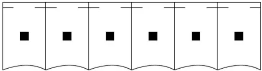
natural_image
Pure diagram of six vertical panels with black squares at each level, no text or symbols present3.5mm Audio Connector
The PF series display has a combination analog audio jack.
The full scale voltage output of the analog audio is 2V RMS. The minimum load impedance is 32.
The analog audio connector has the following pinout.
- Tip: Left audio
- Ring: Right audio
- Sleeve: Ground for audio signal
3.5mm IR Input/Output
The IR blaster generates or receives a space-encoded NEC or Pronto Hex signal. The two transported bit values of the signal (0 and 1) are encoded using different lengths of low-time IR pulses.
The 3.5mm IR in/out port has the following pinout:
- Tip: 3.3V
- Ring: IR Input
- Sleeve: IR Output
*The sleeve is used as a ground during input operations
3.5mm Serial
The UART (asynchronous serial) interface is a 3.5mm (1/8") jack and will interoperate with most RS-232 compatible devices. The receiver will tolerate input voltages between -30V and +30V, with anything below 3V interpreted as a logical 1. The transmitter drives +5V for logical 0 and 0V for logical 1.
The default baud rate of the RS-232 interface is 115200, with no parity, 8 data bits, and 1 stop bit. These settings can be configured in the software. The serial interface supports TX, RX, and ground only -- RTS/CTS hardware flow control is not supported.
A serial plug that is inserted into the 3.5mm jack should use the following signaling:
- Tip: Transmit
- Ring:Receive
- Sleeve: Ground
The following diagram illustrates the behavior of the TX and RX signal:
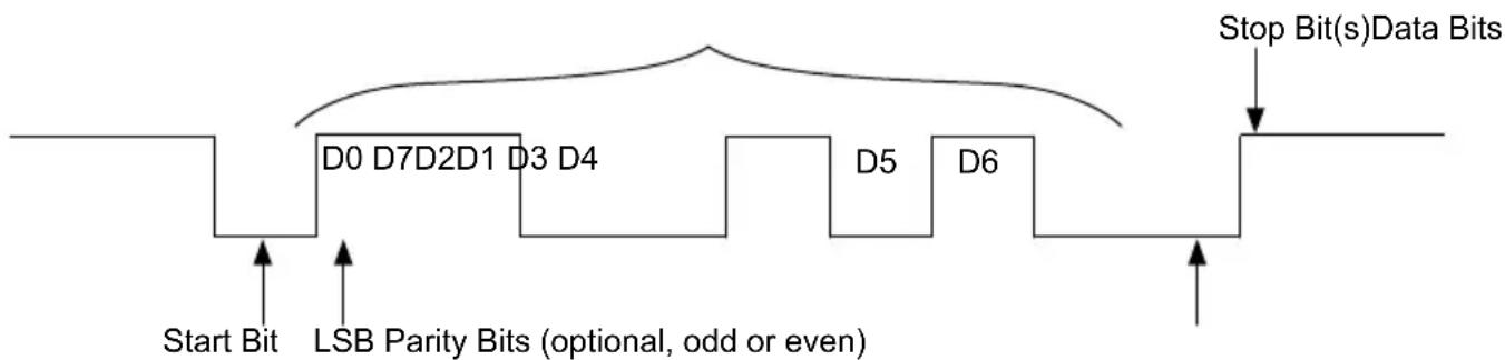
flowchart
graph LR
    Start Bit --> D0_D7_D2_D1_D3_D4
    D0_D7_D2_D1_D3_D4 --> D5_D6
    D5_D6 --> Stop_Bits["Stop Bit(s)Data Bits"]
    D0_D7_D2_D1_D3_D4 --> LSB_ParityBits["LSB Parity Bits (optional, odd or even)"]
    D5_D6 --> D5_D6
    D5_D6 --> Stop_Bits
    D0_D7_D2_D1_D3_D4 --> Stop_Bits
    D5_D6 --> Stop_Bits
    Stop_Bits --> Stop_Bits
On-Board LEDs
There are four on-board LEDs that indicate the following:
| LED Indication | |
| Green file system activity (BSY) F | ashes any time there is file-system activity (on any storage device) |
| Green power (Pwr) Displays when | the board is powered up and not in reset mode. Flashes during firmware update process. |
| Yellow WiFi (▼) Flashes when the | player is connecting to the wireless network. Displays when connected. |
| Red status (Err) Flashes a certain | number of times to indicate which error is occurring. The flash codes are described below. |
| 2 Unspecified error. | |
| 3 Network recovery script is preparing to run on a device configured for network recovery. | |
| 4 No upgrade file found. | |
| 5 Failed to load kernel module. | |
| 6 Board is not capable of running the current firmware version. | |
| 7 A piece of on-board hardware is not working correctly. | |
| 8 Problem related to the storage device (either USB or Micro SD card) | |
| 9 Problem related to the registry/NAND | |
| 10 The autorun script encountered a load/run error. | |
| 11 Wi-Fi related error | |
| 12 Unable to find a bootable image. |
On-Board Switch
The on-board switch is connected to the GPIO02, which is pulled low when the service (SVC) button is pressed. Conversely, a pull up on the button normally sets the GPIO02 to be pulled high.
Reset Switch/GPIO Button
The on-board switch is connected to the reset circuit. Pressing down the reset button will send an initial signal to the system software, and holding the reset button low for approximately 4 seconds will cause a hard reset.
MicroSD Slot
The KIPICT555 has one microSD slot, which supports transfer modes up to UHS-1 DDR50 (50MB/s). There is no inherent limit on the storage capacity of microSD cards used with the player.
Wireless Module
The KIPICT555 display has an internal M.2 slot for installing a compatible wireless module. The M.2 wireless module connects via cable to a single, external, attachable wireless antenna.
Navigating The On Screen Menu
Pressing the menu key on the remote will cause the On Screen Display (OSD) main page to be displayed with two menu tabs: Picture and System settings. Use the cursor keys to move through the various sub menus. Press menu again to quit.
| Picture | |
| Picture Mode | StandardDynamicMildUser |
| Brightness | 50 |
| Color | 50 |
| Sharpness | 50 |
| Tint | 50 |
| Color Temp. | CoolMediumWarmUser |
| System Settings | |
| Menu Languages | English Chinese |
| Software Update (USB) | |
| System Info | |
| Return | |
Specifications subject to change without notice
| Display | |
| Screen Size | 55" |
| Aspect Ratio | 9:16 |
| Resolution | 1920x1080 |
| Active Area | 26.8" (680.4mm)horizontal47.6" (1209mm) vertical |
| Brightness | 450 nits |
| Contrast Ratio | 1100:1 |
| Viewing Angle | 178°x178° |
| Response Time | 12ms |
| Refresh Rate | 60 Hz |
| Life Expectancy | 50,000 hours |
| Speakers | (2) 10 watt |
| Mechanical | |
| Product Size: (W | x H x D)75" x 33" x 3"(1907mm x 827mm x 79.5mm) |
| Package Size (W | x H x D)89" x 40" x 23"(2255mm x 1004mm x 572mm) |
| Net Weight 211 | 6 lbs (96 Kg) |
| Gross Weight 26 | 0.14 lbs (118 Kg) |
| Environmental | |
| Operating Temperature | 32°F to 104°F(0°C to 40°C)humidity 10% to 85% |
| Storage Temperature | -14°F to 140°F(-10°C to 60°C)humidity 10% to 90% |
| Media Formats | |
| Video Codecs H | 265, H.264 ( |
| Video Containers | ts, .mpg, .vob, .mov, .mp4, .m2ts, .wmv |
| Images BMP, | JPEG, PNG |
| Audio Mp2, M | Mp3, ACC, WAV(Ac3 passing through) |
| HTML | |
| AC Adaptor | |
| Input AC~10 | 0-240V, 50-60Hz |
| Power Consumption | 73W (max) |
| Output 12V, 2A | |
| Power supply UL/CBcertified | |
| Input/Output Connections |
| 802.11 bgn Wi-Fi/ Bluetooth Module (M.2 (E) Keyed Connector) |
| Ethernet |
| 3.5mm audio out (analog and digital) |
| USB 2.0 x2 (supports content updates) |
| Phoenix GPIO Port (4pin bi-directional terminal block) |
| 3.5mm RS-232 Serial Port |
| 3.5mm IR In/Out |
| Local Storage |
| External micro SD slot (SDHC, SDXC) |
| SDHC storage up to 32GB SDXC storage up to Tb |
Maintenance
Care Of The Kiosk
Do not rub or strike the kiosk with anything hard as this may scratch, mark, or even damage the kiosk permanently. Ensure that the kiosk is installed in a location where it will be safe from abrasives and flying debris, which could damage the LCD panel. Never pressure wash the screen. Doing so may result in permanent damage. Do not use dry-erase markers on the screen. If dry-erase markers are used on the screen, remove the ink as soon as possible. Never use ammonia or any product containing ammonia, as it will damage the anti-glare coating on the face of the screen. Only use an approved screen cleaner to clean the display face. Unplug the power cord before cleaning the screen. Dust the display by wiping the screen and the cabinet with a soft, clean cloth. If the screen requires additional cleaning, spray water or glass cleaner onto a lint free non-abrasive cloth and them clean the touchscreen. Water or glass cleaner sprayed directly on the screen could possibly leak inside a non-sealed unit and cause damage.
Mobile Telephone Caution
Keep your mobile telephone away from your kiosk to avoid disturbances in the picture or sound, possibly causing permanent damage to your kiosk.
End Of Life Directives
In an effort to produce environmentally friendly products, your new kiosk contains materials that can be recycled and reused. At the end of your kiosk's life, specialized companies can minimize waste by separating reusable materials from non-reusable materials. Please ensure you dispose
of your kiosk according to local regulations. The crossed-out wheeled bin symbol indicated that products should be disposed of in the appropriate recycling stream and not as regular waste.

License Agreement And Trademark Notice

HDMI, the HDMI logo and High-Definition Multimedia Interface are trademarks or registered trademarks of HDMI Licensing LLC in the United States and other countries.
Brightsign is a registered trademark of Brightsign LLC. Avnu, and Avnu Digital are wither registered trademarks of Avnu digital Corporation in the United States and all other countries. All other trademarks are property of their respective owners. Any other trademarks, service marks, personal names or product names are assumed to be the property of their respective owners and are used only for reference. There is no implied sponsorship, affiliation, certification, approval or endorsement if we use one of these terms.
LIMITED ONE-YEAR WARRANTY
ONE-YEAR PARTS & LABOR LIMITED WARRANTY
Terms of Peerless-AV®
The Peerless-AV kiosk is warranted to be free of defects in material and workmanship from the time of purchase by the original owner. If this product is proven to be defective under the terms and conditions of this warranty, Peerless-AV will repair or replace defective parts with new and/or reconditioned parts at no charge for the parts and labor to the original owner, subject to the terms and conditions of this Limited Warranty. This Limited Warranty covers failures due to defects in material or workmanship that occur during normal use as follows:
- Parts – the warranty period for parts is: one (1) year from the date of original purchase. During the applicable Limited Warranty period for parts, defective parts will be replaced at no charge. Parts used for the repair will be warranted for the remainder of the original warranty period for those parts.
- Labor – the warranty period for labor is: one (1) year from the date of original purchase. During the applicable Limited Warranty period for labor, Peerless-AV will provide the labor for warranty repair at no charge for a period of one (1) year from the date of original purchase.
- Original owner must provide verification of the date of purchase when requesting Limited Warranty Services. A copy of the original Dated Sales Receipt is required together with the product serial number to obtain service under this Limited Warranty.
- All repairs must be performed by a Peerless-AV Authorized Service Provider.
- Customer is responsible for returning (including any freight and shipping cost) defective unit to Peerless-AV Authorized Service Provider. If the product is found to have no defects, the customer will be responsible for return shipping costs as well the diagnostic bench fee. If the product is found to be covered by the manufacturer's warranty, Peerless will assume responsibility for return freight charges.
THIS LIMITED WARRANTY DOES NOT COVER:
• Labor to uninstall and reinstall the kiosk.
- Shipping damage.
- Damage caused during customer unpacking, and/or removal of protective packing materials.
- Damage due to improper, incorrect or insufficient AC voltage, power surges or lightning strikes.
- Damage due to inadequate signal pickup, incorporation into other products or repairs by anyone other than a Peerless-AV Technician.
- Damage due to tampering or removal of any screws.
- Damage which results from fire, flood, lightning, tornado, hurricane, large hail, extremely gusty winds, sand storms, vandalism, terrorism or other acts of nature.
- Any unit which has been modified or damaged due to improper installation or failure to obey the operating instructions provided in the User Manual.
- Any failure, loss, damage or personal injury due to accident, neglect, misuse, abuse, improper operation, improper storage, alteration to the unit, or failure by the consumer to follow operating instructions provided in the User Manual.
- Any owner other than the original owner.
- Any unit purchased from an unauthorized seller.
- If the original product serial number has been removed, defaced or tampered with in any way.
- Any packaging or transportation charges incurred in connection with warranty services.
- Indirect, consequential, or special damages except as required by federal or state laws.
- Any unit tampered with, modified, adjusted, or repaired by any party other than the Peerless-AV Authorized Service Provider.
- Any cosmetic damages to the surface or exterior that has been defaced or faded, or caused by normal wear and tear or exposure to chemicals, acid rain, large hail or adverse weather conditions.
- Minor cabinet blemishes or minor scratches to the exterior of the unit or other cosmetic imperfections that are not within the viewable area of the LCD.
- The LCD is a Class 2 ISO panel. As such, the Pixel Fault for Class II Panels states:
• Type 1 = Hot Pixel (always on – white);
• Type 2 = Dead Pixel (always off – black); or
- Type 3 = A Stuck Pixel (one or more sub-pixels (red, blue or green) are always on or always off.
- The total number of permitted defects per 2 million pixels:
- Type 1 = (4)
-
Type 2 = (4)
• Type 3 = (10) -
Picture quality when installed in direct sunlight where sun is shining directly on the face of the LCD.
- Any damage, scratches or blemishes to the face of the LCD and/or exterior cabinet due to end-user cleaning.
- Dirty air waves, and/or unusual signal interference due to weak signal from multi-wire runs, weak signal from cable or satellite service providers, or unusual signal interference.
- Any damage incurred through improper packaging. If the kiosk needs to be returned, original packaging is required. (If packaging is needed, the end user is required to contact a Peerless-AV Care Customer Representative to request a new box to be delivered to customer shipping site)
- Return shipping when no defect is found.
For Non-Warrantied Repairs, or for claims found to not be covered by the Limited Warranty, the customer will be responsible for the diagnostic bench fee, the cost of replacement parts, and any applicable shipping charges. Repaired Non-Warrantied claims require payment in full before repaired products are returned to customer.
Peerless-AV and its representatives or agents shall in no event be liable for any general, indirect or consequential damages arising out of/or caused by the use of/or inability to use this product.
The Warranty is made in lieu of all other warranties, expressed or implied, and all other liabilities on the part of Peerless-AV. Any other warranties, including warranties of merchantability and fitness for a particular purpose are hereby disclaimed by Peerless-AV and its representatives and/or agents.
The laws of some states do not allow exclusion of implied warranties; therefore, this warranty shall be deemed modified to be consistent with such laws. This limited Warranty gives you specific legal rights. You may also have other rights that vary from state to state.
All warranty inspections and repairs must be performed by Peerless-AV or its authorized service representatives.
Please call 800.865.2112 or 630.375.5100 so that the Peerless-AV technical support team can assist with proper troubleshooting steps. Please have your receipt and serial number available during the time of call while onsite. Technical support will determine whether the product will need to be replaced or returned for repair. If a repair is needed Customer Care will issue a Return Material Authorization (RMA) number. The product will need to be in the original packaging and banded to a skid in the upright position. If the product is not covered by the warranty, Peerless-AV will contact you with repair estimates after inspection.
© 2017 Peerless Industries, Inc. All rights reserved.
ENG This page intentionally left blank.
ENG This page intentionally left blank.
peerless-AV®
Peerless-AV
2300 White Oak Circle
Aurora, IL 60502
Email: tech@peerlessmounts.com
Ph: (800) 865-2112
Fax: (800) 359-6500
www.peerless-av.com
Peerless-AV Europe
Unit 3 Watford Interchange,
Colonial Way, Watford, Herts.
WD24 4WP, United Kingdom
Customer Care
44 (0) 1923 200 100
www.peerless-av.com
Peerless-AV de Mexico


- WARNING
- RISK OF ELECTRICAL SHOCK
- Read before operating equipment
- Batteries Installed Warning
- CAUTION:
- FCC STATEMENT
- Canada
- Relevant Information
- SET UP INSTRUCTIONS
- Parts List
- Description Qty
- Connecting Cables
- Power Source
- Connect To The Power Source
- CAUTION
- Remote Control Battery Installation And Replacement
- Using The Remote Control
- OPERATING INSTRUCTIONS
- Power On/Off Your New Kiosk
- Getting Started
- Power Connector
- Wi-Fi / Bluetooth
- RJ45 LAN
- USB
- GPIO
- 2 3 4 5 6
- 3.5mm Audio Connector
- 3.5mm IR Input/Output
- 3.5mm Serial
- On-Board LEDs
- On-Board Switch
- Reset Switch/GPIO Button
- MicroSD Slot
- Wireless Module
- Navigating The On Screen Menu
- Maintenance
- Care Of The Kiosk
- Mobile Telephone Caution
- End Of Life Directives
- License Agreement And Trademark Notice
- LIMITED ONE-YEAR WARRANTY
- ONE-YEAR PARTS & LABOR LIMITED WARRANTY
- Terms of Peerless-AV®
- THIS LIMITED WARRANTY DOES NOT COVER:
- peerless-AV®
Brand : Peerless-AV
Model : KIPICT555
Category : Mounting bracket