
AVX-DVI-FO-SP4 - KVM switch Black Box - Free user manual and instructions
Find the device manual for free AVX-DVI-FO-SP4 Black Box in PDF.

| Product Type | 4-Port Fiber Splitter for DVI-D and Stereo Audio |
| Model | AVX-DVI-FO-SP4 |
| Dimensions | 0.6" H x 1.5" W x 2.7" D (1.5 x 3.9 x 6.9 cm) |
| Weight | 0.2 lb (0.1 kg) |
| Power Requirement | Passive, no external power needed |
| Connectors | 5 LC fiber optic connectors (1 input, 4 outputs) |
| Video Support | DVI-D, up to WUXGA (1920 x 1200), 24-bit color |
| Audio Support | Stereo audio, transmitted over same fiber |
| Fiber Type | Single-mode or multimode (single-mode recommended for distance) |
| Maximum Distance | Up to 1.5 km (4921 ft) over single-mode fiber |
| Optical Loss | 6 dB |
| Operating Temperature | 32 to 122°F (0 to +50°C) |
| Compliance | DVI 1.0, FCC Class A, Industry Canada Class A |
| Maintenance | Keep connectors clean; no user-serviceable parts |
| Safety | Not for residential use; may cause interference |
| Spare Parts & Repairability | Contact Black Box Technical Support for replacements; no user repair |
| Included Accessories | 1x 4-Port Fiber Splitter only (no power supply) |
| Additional Information | Part of the Mini Extender Kit series; passive distribution |
Frequently Asked Questions - AVX-DVI-FO-SP4 Black Box
User questions about AVX-DVI-FO-SP4 Black Box
0 question about this device. Answer the ones you know or ask your own.
Ask a new question about this device
Download the instructions for your KVM switch in PDF format for free! Find your manual AVX-DVI-FO-SP4 - Black Box and take your electronic device back in hand. On this page are published all the documents necessary for the use of your device. AVX-DVI-FO-SP4 by Black Box.
USER MANUAL AVX-DVI-FO-SP4 Black Box
Mini Extender Kit for DVI-D and Stereo Audio over Fiber
Extend DVI-D video and stereo audio up to 1.5 kilometers over a strand of single-mode fiber distribute DVI-D and stereo audio to 32 displays.

natural_image
Two black BLACK BOX devices with visible ports and connectors, no text or symbols on the devices themselves.Customer Support Information
Order toll-free in the U.S.: Call 877-877-BBOX (outside U.S. call 724-746-5500) FREE technical support 24 hours a day, 7 days a week: Call 724-746-5500 or fax 724-746-0746 Mailing address: Black Box Corporation, 1000 Park Drive, Lawrence, PA 15055-1018
Web site: www.blackbox.com • E-mail: info@blackbox.com
FEDERAL COMMUNICATIONS COMMISSION AND INDUSTRY CANADA RADIO FREQUENCY INTERFERENCE STATEMENTS
This equipment generates, uses, and can radiate radio-frequency energy, and if not installed and used properly, that is, in strict accordance with the manufacturer's instructions, may cause interference to radio communication. It has been tested and found to comply with the limits for a Class A computing device in accordance with the specifications in Subpart B of Part 15 of FCC rules, which are designed to provide reasonable protection against such interference when the equipment is operated in a commercial environment. Operation of this equipment in a residential area is likely to cause interference, in which case the user at his own expense will be required to take whatever measures may be necessary to correct the interference.
Changes or modifications not expressly approved by the party responsible for compliance could void the user's authority to operate the equipment.
This digital apparatus does not exceed the Class A limits for radio noise emission from digital apparatus set out in the Radio Interference Regulation of Industry Canada.
Trademarks Used in this Manual
Black Box and the Double Diamond logo are registered trademarks of BB Technologies, Inc.
Any other trademarks mentioned in this manual are acknowledged to be the property of the trademark owners.
Contents
- Specifications 7
- Overview 8
2.1 Introduction....8
2.2 Features 8
2.3 What's Included 9
2.4 Hardware Description 10
2.4.1 AVX-DVI-FO-MINI and AVX-DVI-FO-MINI-RX 10
2.4.2 AVX-DVI-FO-SPCS 11
2.4.3 AVX-DVI-FO-SP4 12
2.4.4 AVX-DVI-FO-SP8 13
2.4.5 AVX-DVI-FO-USBPS....14
2.5 System Configuration....14
2.5.1 AVX-DVI-FO-MINI and AVX-DVI-FO-MINI-RX 14
2.5.2 AVX-DVI-FO-SPCS 15
2.5.3 AVX-DVI-FO-SP4 16
2.5.4 AVX-DVI-FO-SP8 17
- Installation 18
3.1 Connections 18
3.2 EDID Setting....18
3.3 Installation Steps 20
- Troubleshooting 25
4.1 Problems/Solutions 25
4.2 Contacting Black Box 26
4.3 Shipping and Packaging 26
1. Specifications
Color Depth — 24-bit true color
Data Rate — 5 Gbps (2.5 Gbps per single wavelength)
Distance — Multimode cable: 1640.4 ft. (500 m);
Single-mode cable: 4921.3 ft. (1.5 km)
Fiber Type — Single-mode or multimode
Optical Budget — 16 dB
Receiver Sensitivity — -21 dB
Resolutions — Supports up to WUXGA (1920 x 1200)
Wavelength — 1310 nm/1550 nm (dual wavelength)
Operating Temperature — 32 to 122°F (0 to +50°C)
Power Consumption — 2.5 W max.
Video Standard — Complies with DVI 1.0
Indicators — (1) two-color LED for Power and Link status
Connector — AVX-DVI-FO (kit): Receiver: (1) 24-pin DVI-D, (2) 3.5-mm audio, (1) barrel connector for power;
Transmitter: (1) 24-pin DVI-D, (2) 3.5-mm audio, (1) barrel connector for power;
Splitters: AVX-DVI-FO-SPCS: (3) LC connectors: (1) for interconnect, (2) for devices;
AVX-DVI-FO-SP4: (5) LC connectors: (1) for interconnect, (4) for devices;
AVX-DVI-FO-SP8: (9) LC connectors: (1) for interconnect, (8) for devices
NOTE: The splitters transmit both audio and video signals over one single-strand, single-mode fiber cable.
Size — 0.6"H x 1.5"W x 2.7"D (1.5 x 3.9 x 6.9 cm)
Weight — 0.2 lb. (0.1 kg)
2. Overview
2.1 Introduction
The DVI Extender transmits high-quality video signal formats and audio to a remote screen, without compromising the original media quality. The DVI Extender delivers a full HD resolution signal through one fiber optic cable up to 1.5 kilometers. It's an ideal solution for systems where high-resolution and high-quality video signals need to be displayed over long distances.
Connect the extender in a point-to-point configuration to transmit high-resolution video to a remote display. The transmitter module is compatible with all kinds of display devices. It reads and stores the display's EDID information to prevent EDID handshake problems. Installing the extender is easy and more flexible than ever.
Connect the extender in a point-to-multipoint configuration to distribute high-resolution video to up to 32 displays. Use the 2-, 4-, and 8-port splitters to achieve flawless video distribution and extension. All splitters are passive devices and do not require external power.
Typical applications include public informational displays in elevators, trains, subways, airports, shopping malls, museums, or hotels.
2.2 Features
- Delivers high-quality multimedia content in real time from a media player to a distant screen while maintaining crystal-clear video. A high-definition video signal from a single player to a display can be extended up to 1.5 km without electrical support for splitters. The DVI Extender increases the range of the display network and enables you to set up your screens at any locations without sacrificing the quality of media.
- Supports audio extension. The DVI Extender transmits both audio and video over a single-strand fiber optic cable.
- Extends all DVI VESA standards all the way up to a 1920 x 1200 resolution.
- Offers programmable EDID. The transmitter reads and stores the display's EDID information and provides a handshaking capability for any type of display with different resolutions.
- Consumes very little power. Transmitters and receivers consume 3 W or less for transmitting and receiving Full HD resolution video signals and CD-quality audio.
- Split, extend, and distribute DVI video and stereo audio using the passive fiber splitters.
2.3 What's Included
Your package should contain the following items. If anything is missing or damaged, contact Black Box Technical Support at 724-746-5500 or info@blackbox.com.
AVX-DVI-FO-MINI:
• (1) Mini Fiber Transceiver
• (1) Mini Fiber Receiver
• (2) 5-VDC wallmount power supplies with international adapters for U.S., U.K., AU, and EU
• (2) 5-ft. (1.5-m) male-male 3.5-mm audio cables
- This user's manual
AVX-DVI-FO-MINI-RX:
• (1) Mini Fiber Receiver
• (1) 5-VDC wallmount power supply with international adapters for U.S., U.K., AU, and EU
• (1) 5-ft. (1.5-m) male-male 3.5-mm audio cable
- This user's manual
AVX-DVI-FO-SPCS:
• (1) 2-Port Fiber Splitter
AVX-DVI-FO-SP4:
• (1) 4-Port Fiber Splitter
AVX-DVI-FO-SP8:
• (1) 8-Port Fiber Splitter
The DVI Extender is the best system to use when extending high-quality DVI video and stereo audio over long distances. The extender includes a transmitter module and a receiver module.
The transmitter module encodes the audio/video signals into an optical signal and the receiver module decodes the optical signal back into the original audio/video signal.
In point-to-point transmission, each display needs a transmitter and a receiver to extend the source.
2.4 Hardware Description
2.4.1 AVX-DVI-FO-MINI and AVX-DVI-FO-MINI-RX
Figure 2-1 shows the transmitter and receiver kit (AVX-DVI-O-MINI). Table 2-1 describes its components. The receiver is also sold separately (AVX-DVI-FO-MINI-RX).

Figure 2-1. Transmitter and Receiver.
Table 2-1. Transmitter and Receiver components.
| Number Component Description |
| 1 DVI-D connector Links to monitor |
| 2 DVI-D connector Connects to PC |
| 3 Power connector Connects to 5-VDC power input |
| 4 Stereo audio out Audio in to monitor/speakers |
| 5 (1) LC connector Links to fiber interconnect |
| 6 Power in Connects to 5-VDC power input |
| 7 Stereo audio in Audio out from PC |
| 8 (1) LC connector Links to fiber interconnect |
2.4.2 AVX-DVI-FO-SPCS
Figures 2-2 and 2-3 show the side panels of the AVX-DVI-FO-SPCS. Table 2-2 describes its components.
natural_image
Pure technical line drawing of a mechanical component with no text or symbolsFigure 2-2. AVX-DVI-FO-SPCS side panel 1.

natural_image
Technical line drawing of a two-pin electrical connector (no text or symbols)Figure 2-3. AVX-DVI-FO-SPCS side panel 2.
Table 2-2. AVX-DVI-FO-SPCS components.
| Number Component Description |
| 1 (1) LC connector Links to fiber interconnect. |
| 2 (2) LC connectors Link to fiber devices. |
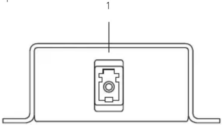
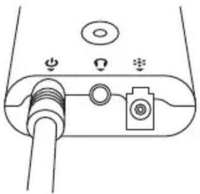
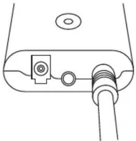
2.4.3 AVX-DVI-FO-SP4
Figures 2-4 shows the side panel of the AVX-DVI-FO-SP4. Table 2-3 describes its components. The panel on the opposite side is blank.

Figure 2-4. AVX-DVI-FO-SP4 side panel.
Table 2-3. AVX-DVI-FO-SP4 components.
| Number Component Description |
| 1 (1) LC connector Links to fiber interconnect. |
| 2 (4) LC connectors Link to fiber devices. |
2.4.4 AVX-DVI-FO-SP8
Figure 2-5 shows the side panel of the AVX-DVII-FO-SP8. Table 2-4 describes its components. The panel on the opposite side is blank.

Figure 2-5. AVX-DVI-FO-SP8 side panel.
Table 2-4. AVX-DVI-FO-SP8 components.
| Number Component Description |
| 1 (1) LC connector Links to fiber interconnect |
| 2 (8) LC connectors Link to fiber devices |
2.4.5 AVX-DVI-FO-USBPS
The AVX-DVI-FO-USBPS is a USB Type A male to a 1.35-mm barrel plug. It can supply 5-VDC to the AVX-DVI-FO-MINI transmitter and/or receiver.
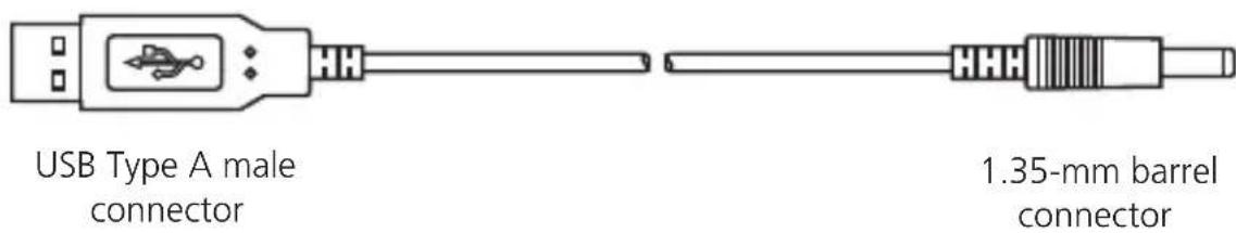
Figure 2-6. AVX-DVI-FO-USBPS.
2.5 System Configuration
2.5.1 AVX-DVI-FO-MINI and AVX-DVI-FO-MINI-RX
The transmitter module encodes the audio/video signal into an optical signal and the receiver module decodes the optical signal back into the original audio/video signal. Figure 2-7 illustrates this application.

Figure 2-7. AVX-DVI-FO-MINI kit Configuration.
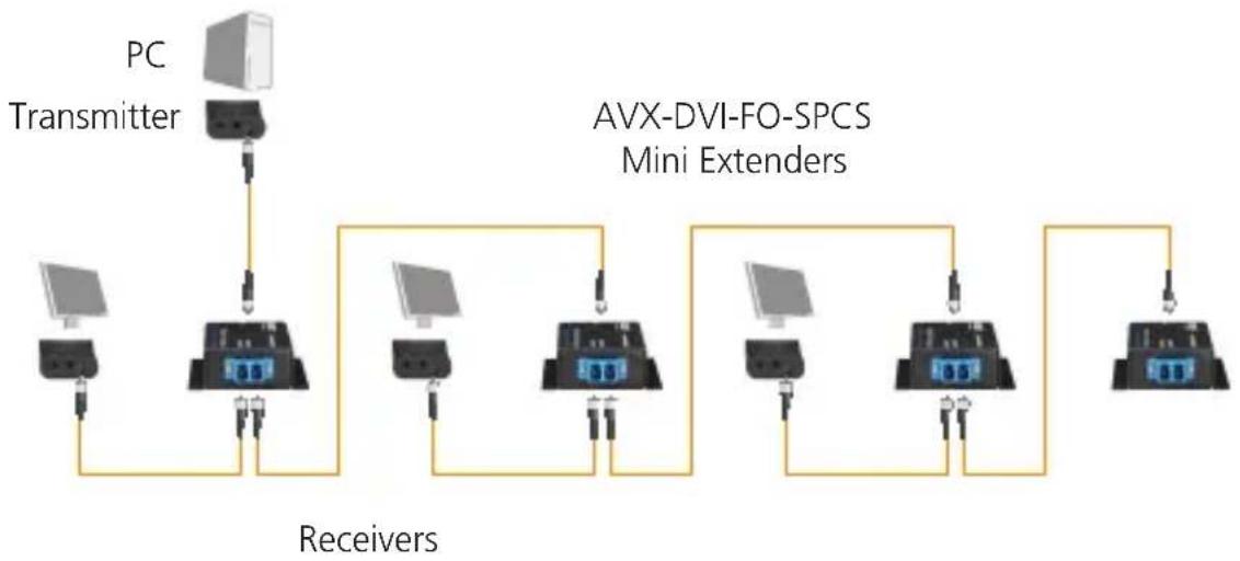
2.5.2 AVX-DVI-FO-SPCS
Figure 2-8 shows an application using the AVX-DVI-FO-SPCS mini extenders.
flowchart
graph TD
    A["PC Transmitter"] --> B["AVX-DVI-FO-SPCS Mini Extenders"]
    B --> C["Receiver"]
    C --> D["Computer 1"]
    C --> E["Computer 2"]
    C --> F["Computer 3"]
    C --> G["Computer 4"]
    C --> H["Computer 5"]
    C --> I["Computer 6"]
    C --> J["Computer 7"]
    C --> K["Computer 8"]
    C --> L["Computer 9"]
    C --> M["Computer 10"]
Figure 2-8. AVX-DVI-FO-SPCS.
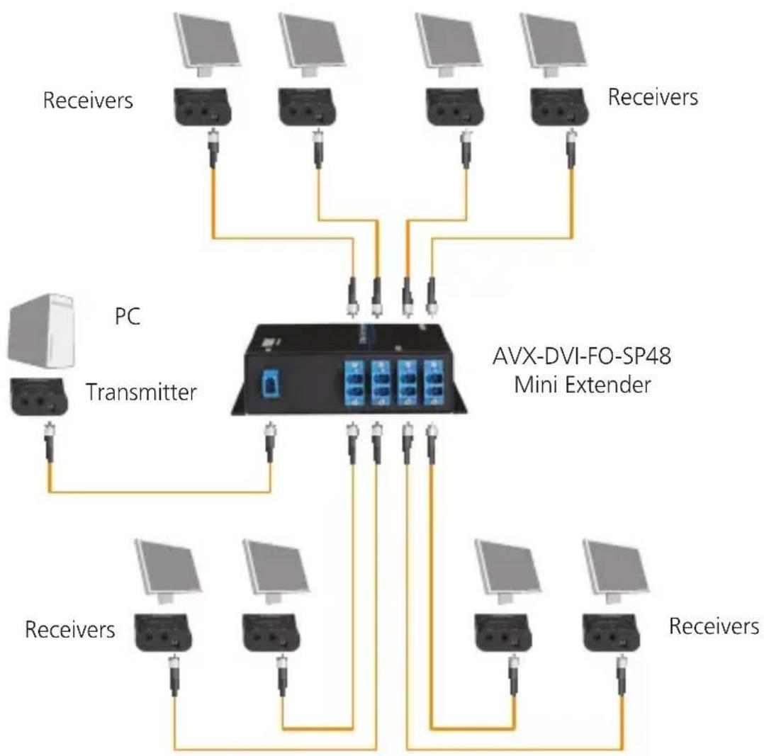
2.5.3 AVX-DVI-FO-SP4
Figure 2-9 shows an application using an AVX-DVI-FO-SP4 mini extender.

flowchart
graph TD
    A["PC"] --> B["Transmitter"]
    B --> C["Receiver"]
    C --> D["Receiver"]
    D --> E["AVX-DVI-FO-SP4 Mini Extender"]
    E --> F["ReceiverReceiver"]
    F --> G["Receiver"]
    G --> H["Receiver"]
    H --> I["Receiver"]
    I --> J["Receiver"]
    J --> K["Receiver"]
    K --> L["Receiver"]
    L --> M["Receiver"]
    M --> N["Receiver"]
    N --> O["Receiver"]
    O --> P["Receiver"]
    P --> Q["Receiver"]
    Q --> R["Receiver"]
    R --> S["Receiver"]
    S --> T["Receiver"]
    T --> U["Receiver"]
    U --> V["Receiver"]
    V --> W["Receiver"]
    W --> X["Receiver"]
Figure 2-9. AVX-DVI-FO-SP4.
2.5.4 AVX-DVI-FO-SP8
Figure 2-10 shows an application using an AVX-DVI-FO-SP8 mini extenders.
flowchart
graph TD
    PC["PC"] --> Transmitter["Transmitter"]
    Transmitter --> AVX_DVI-FO-SP48["AVX-DVI-FO-SP48 Mini Extender"]
    AVX_DVI-FO-SP48 --> multiple1["100+ microphones"]
    AVX_DVI-FO-SP48 --> multiple2["100+ microphones"]
    AVX_DVI-FO-SP48 --> multiple3["100+ microphones"]
    AVX_DVI-FO-SP48 --> multiple4["100+ microphones"]
    Transmitter --> multiple5["100+ microphones"]
    Transmitter --> multiple6["100+ microphones"]
    Transmitter --> multiple7["100+ microphones"]
    Transmitter --> multiple8["100+ microphones"]
    Transmitter --> multiple9["100+ microphones"]
    Transmitter --> multiple10["100+ microphones"]
    Transmitter --> multiple11["100+ microphones"]
    Transmitter --> multiple12["100+ microphones"]
    Transmitter --> multiple13["100+ microphones"]
    Transmitter --> multiple14["100+ microphones"]
    Transmitter --> multiple15["100+ microphones"]
    Transmitter --> multiple16["100+ microphones"]
    Transmitter --> multiple17["100+ microphones"]
    Transmitter --> multiple18["100+ microphones"]
    Transmitter --> multiple19["100+ microphones"]
    Transmitter --> multiple20["100+ microphones"]
    Transmitter --> multiple21["100+ microphones"]
    Transmitter --> multiple22["100+ microphones"]
    Transmitter --> multiple23["100+ microphones"]
    Transmitter --> multiple24["100+ microphones"]
    Transmitter --> multiple25["100+ microphones"]
    Transmitter --> multiple26["100+ microphones"]
    Transmitter --> multiple27["100+ microphones"]
    Transmitter --> multiple28["100+ microphones"]
    Transmitter --> multiple29["100+ microphones"]
    Transmitter --> multiple30["100+ microphones"]
    Transmitter --> multiple31["100+ microphones"]
    Transmitter --> multiple32["100+ microphones"]
    Transmitter --> multiple33["100+ microphones"]
    Transmitter --> multiple34["100+ microphones"]
    Transmitter --> multiple35["100+ microphones"]
    Transmitter --> multiple36["100+ microphones"]
    Transmitter --> multiple37["100+ microphones"]
    Transmitter --> multiple38["100+ microphones"]
    Transmitter --> multiple39["100+ microphones"]
    Transmitter --> Multiple40["100+ microphones"]
    Transmitter --> Multiple41["100+ microphones"]
    Transmitter --> Multiple42["100+ microphones"]
    Transmitter --> Multiple43["100+ microphones"]
    Transmitter --> Multiple44["100+ microphones"]
    Transmitter --> Multiple45["100+ microphones"]
    Transmitter --> Multiple46["100+ microphones"]
    Transmitter --> Multiple47["100+ microphones"]
    Transmitter --> Multiple48["100+ microphones"]
    Transmitter --> Multiple49["100+ microphones"]
    Transmitter --> Multiple50["100+ microphones"]
Figure 2-10. AVX-DVI-FO-SP8.
3. Installation
3.1 Connections
Connect the transmitter module to the DVI port on the PC/video card and connect the receiver module to the DVI port on the digital display device.
Use the DVI Extender with an LC fiber optic cable (single-mode optical fiber: 9/125 μm).
3.2 EDID Setting
The transmitter has a basic EDID table built in that includes the most commonly used display modes. If you encounter problems selecting the right resolution and would like to copy the EDID table from your monitor, follow these instructions:
- Connect the transmitter to the DVI port on the monitor.
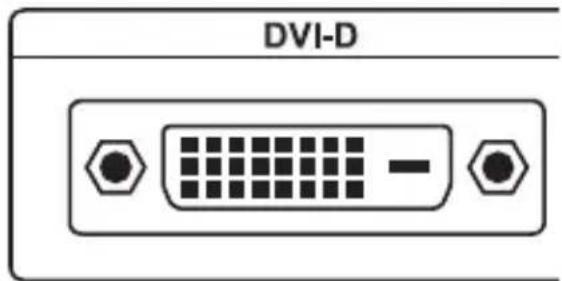
Figure 3-1. DVI-D connector on the monitor.
Figure 3-2. Transmitter plugged into remote monitor.
- Connect the DC power to the transmitter and power on the monitor.
natural_image
Diagram of a device with labeled ports and connectors (no text or symbols)Figure 3-3. DC power on transmitter.
- Use a paper clip to press the switch located on the transmitter for a moment.

natural_image
Technical line drawing of a mechanical component with a circular feature and tool (no text or symbols)Figure 3-4. Switch on the transmitter.
- Check the LED status. If the transmitter has completely read the monitor's EDID, the blue LED will turn off and on by itself three times.
- To use the factory setting, press the switch for 3 seconds. The red LED will blink three times.
3.3 Installation Steps
- Connect the transmitter to the DVI source.
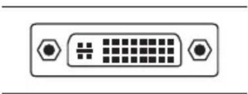
natural_image
Front panel of a D-sub connector with hexagonal connectors (no text or symbols)Figure 3-5. DVI source connector.

natural_image
Line drawing of a device with two connectors and a central button (no text or symbols)Figure 3-6. Transmitter connected to DVI source.
- Connect the receiver to the monitor.

Figure 3-7. DVI connector on monitor.
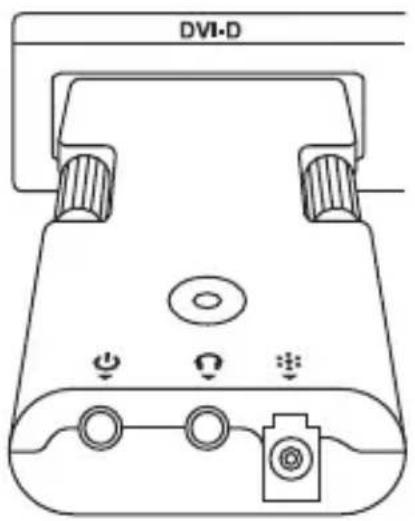
Figure 3-8. Power on the monitor.
- Connect the DC power to the transmitter and the receiver.
natural_image
Diagram of a device interface with ports and connectors (no text or symbols)Figure 3-9. DC power on the transmitter.
natural_image
Line drawing of a device with a connector and cable (no text or symbols)Figure 3-10. DC power on the receiver.
A blue light illuminates while the power is on.
- Connect the fiber cable to the transmitter and the receiver.

natural_image
Technical line drawing of a mechanical or electrical component with no visible text or symbolsFigure 3-11. Fiber cable on the transmitter.

natural_image
Pure technical line drawing of a mechanical component with no text or symbolsFigure 3-12. Fiber cable on the receiver.
- Power on the display and restart the DVI source.
The LED on the transmitter shows a violet light while the transmitter is receiving a normal video signal from the DVI source. Check your DVI source if the LED does not show any activity. The LED on the receiver shows a violet light while the receiver is sensing a normal video signal from the optical cable.
Table 3-1. Console port pin assignments.
| Device | LEDColor Meaning | |
| Transmitter | Blue Power is on. | |
| Violet | Transmitter is receiving a normal video signal from the DVI source. | |
| Receiver | Blue Power is on. | |
| Violet | Receiver is receiving a normal video signal from the transmitter. | |
The extender supports audio extension.
- Connect the transmitter to the DVI source and audio source.
- Connect the receiver to the display and the speaker(s).
- Connect the fiber cable between the transmitter and the receiver or connect any splitters.
- Connect the DC power to the transmitter and the receiver.
- Power on the display(s).
- Restart the DVI source.
Table 3-2. Loss chart.
| Product Code Amount of Loss |
| AVX-DVI-FO-SPCS 3 dB loss |
| AVX-DVI-FO-SP4 6 dB loss |
| AVX-DVI-FO-SP8 9 dB loss |
4. Troubleshooting
4.1 Problems/Solutions
Problem: No image
Solutions:
- Make sure the PC power is on.
- Check whether the computer and the monitor are properly connected.
- Turn the PC power on and off.
- Make sure the fiber cable between the transmitter and the receiver is properly connected.
- Check whether the LED on the transmitter shows a violet light. If the LED does not show any activity, the video settings on the PC may be incorrect.
- Make sure the LED on the receiver shows a violet light. If the LED does not show any activity, the signal from the fiber cable is missing. Check the cable connections.
Problem: Screen artifacts appear.
Solution: Check the resolution of the DVI source. This device supports up to a 1920 x 1200 WUXGA resolution.
Problem: No sound
Solutions:
- Make sure the power is on for the audio source.
- Check whether the speaker power is on.
- Make sure the audio cable is correctly connected.
4.2 Contacting Black Box
If you determine that your DVI Extender is malfunctioning, do not attempt to alter or repair the unit. It contains no user-serviceable parts. Contact Black Box Technical Support at 724-746-5500 or info@blackbox.com.
Before you do, make a record of the history of the problem. We will be able to provide more efficient and accurate assistance if you have a complete description, including:
- the nature and duration of the problem.
- when the problem occurs.
- the components involved in the problem.
- any particular application that, when used, appears to create the problem or make it worse.
4.3 Shipping and Packaging
If you need to transport or ship your DVI Extender:
- Package it carefully. We recommend that you use the original container.
- If you are returning the unit, make sure you include everything you received with it. Before you ship for return or repair, contact Black Box to get a Return Authorization (RA) number.
Black Box Tech Support: FREE! Live. 24/7.
Tech support the way it should be.

natural_image
Close-up portrait of a smiling man holding a phone to her ear (no visible text or symbols)Great tech support is just 30 seconds away at 724-746-5500 or blackbox.com.

BLACK BOX®
NETWORK SERVICES
About Black Box
Black Box provides an extensive range of networking and infrastructure products. You'll find everything from cabinets and racks and power and surge protection products to media converters and Ethernet switches all supported by free, live 24/7 Tech support available in 30 seconds or less.
© Copyright 2012. Black Box Corporation. All rights reserved.
AVX-DVI-FO-MINI, version 3


- FEDERAL COMMUNICATIONS COMMISSION AND INDUSTRY CANADA RADIO FREQUENCY INTERFERENCE STATEMENTS
- Trademarks Used in this Manual
- Contents
- Specifications
- Overview
- Introduction
- Features
- What's Included
- AVX-DVI-FO-MINI:
- AVX-DVI-FO-MINI-RX:
- AVX-DVI-FO-SPCS:
- AVX-DVI-FO-SP4:
- AVX-DVI-FO-SP8:
- Hardware Description
- AVX-DVI-FO-MINI and AVX-DVI-FO-MINI-RX
- AVX-DVI-FO-SPCS
- AVX-DVI-FO-SP4
- AVX-DVI-FO-SP8
- AVX-DVI-FO-USBPS
- System Configuration
- AVX-DVI-FO-MINI and AVX-DVI-FO-MINI-RX
- AVX-DVI-FO-SPCS
- AVX-DVI-FO-SP4
- AVX-DVI-FO-SP8
- Installation
- Connections
- EDID Setting
- Installation Steps
- Troubleshooting
- Problems/Solutions
- Problem: No image
- Solutions:
- Problem: No sound
- Contacting Black Box
- Shipping and Packaging
- Black Box Tech Support: FREE! Live. 24/7.
- BLACK BOX®
- NETWORK SERVICES
- About Black Box
Brand : Black Box
Model : AVX-DVI-FO-SP4
Category : KVM switch