
99-7605 - Car Installation Kit Metra - Free user manual and instructions
Find the device manual for free 99-7605 Metra in PDF.

| Product Type | Dash Installation Kit |
| Brand | Metra |
| Model | 99-7605 |
| Compatible Vehicles | Infiniti G35 Coupe (2005-2007), Infiniti G35 Sedan (2005-2006) |
| Radio Provision | ISO DIN Mount |
| Finish | Painted and finished to match factory dash |
| Material | ABS Plastic |
| Color | Black (matched to OEM) |
| Dimensions (Approx.) | 7 x 2 x 4 inches |
| Weight (Approx.) | 0.5 lbs |
| Package Contents | Radio housing, climate control cable, installation instructions |
| Required Tools | Small flat blade screwdriver, Phillips screwdriver, hook tool, panel removal tool |
| Installation Type | DIY, moderate difficulty |
| Wiring | EIA color code, includes adapter orientation |
| Climate Control Compatibility | Retains factory climate controls with included cable |
| Safety | Disconnect battery before installation; tape unused wires |
| Warranty | 1 year limited warranty (from Metra) |
| Maintenance | Wipe with soft dry cloth; avoid harsh chemicals |
| Reparability | Replacement parts available via Metra; lifetime support |
Frequently Asked Questions - 99-7605 Metra
User questions about 99-7605 Metra
0 question about this device. Answer the ones you know or ask your own.
Ask a new question about this device
Download the instructions for your Car Installation Kit in PDF format for free! Find your manual 99-7605 - Metra and take your electronic device back in hand. On this page are published all the documents necessary for the use of your device. 99-7605 by Metra.
USER MANUAL 99-7605 Metra
INSTALLATION INSTRUCTIONS FOR PART 99-7605
APPLICATIONS
INFINITI G35 Coupe 2005-07
INFINITI G35 Sedan 2005-06
Painted And Finished To Match Factory Dash
99-7605
KIT FEATURES
• ISO Mount Radio Provision
natural_image
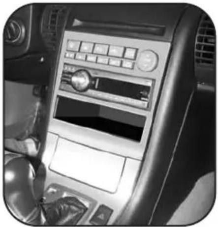
Interior view of a car dashboard with control panel and steering wheel (no visible text or symbols)KIT COMPONENTS
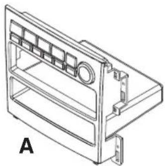
A) Radio Housing B) Climate Control Cable
natural_image
Technical line drawing of a mechanical housing or enclosure with internal compartments and mounting brackets (no text or symbols)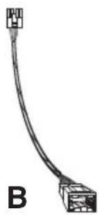
natural_image
Pure electrical connector diagram without any text or symbolsTOOLS REQUIRED:
Small Flat Blade Screwdriver/ Panel Removal Tool
- Phillips Screwdriver - Hook Tool

natural_image
Line drawings of four different screwdriver tools (no text or symbols)TABLE OF CONTENTS
Dash Disassembly
- Infiniti G35 Coupe 2005-2007/G35 Sedan 2005-06 .....1,2
Kit Assembly
ISO Mount Radio Provision ....3
Final Assembly 4
*Note:
Refer also to the instructions included with the aftermarket radio.
INFINITI G35 Coupe 2005-07 / INFINITI G35 Sedan 2005-06
1 Disconnect the negative battery terminal to prevent an accidental short circuit.
2 Push down on the collar below the shift knob to unclip. Using a small screwdriver or hook tool remove the spring clip to release and remove the shift knob. (Figure A)
3 Unclip and remove the shifter trim panel including the ashtray/cigarette lighter. (Figure B)
4 Remove (2) Phillips screws (exposed under the trim panel removed in step 3) from the panels on the left and right side of the radio/climate control panel assembly. (Figure C)
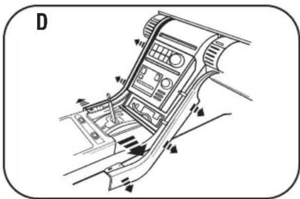
5 Unclip and remove the trim panels on the left and right side of the radio/climate control panel assembly.
(Figure D)
6 Unclip and remove the thin plastic trim piece at top edge of dash. (Figure E)
7 Unclip and remove the hood panel above the clock on the top of the dash. (Figure F)
Continued on page 2.

natural_image
Line drawing of a car air intake manifold with control panel and directional arrows (no text or symbols)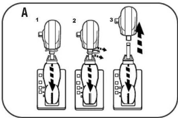

natural_image
Diagram of a car gear shift lever with labeled components and directional arrows (no text or symbols beyond labels)
natural_image
Diagram of a car air intake system with directional arrows indicating airflow or movement (no text or labels)INFINITI G35 Coupe 2005-07 / INFINITI G35 Sedan 2005-06
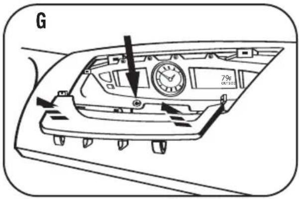
8 Unclip and remove the trim panel at the bottom of the clock panel then remove the (1) Phillips screw exposed below it. (Figure G)
9 Remove (2) Phillips screws below the radio/climate control panel and (2) Phillips screws at the top of the radio/climate control panel assembly (between the a/c vents). (Figure H)
10 Unclip the radio/climate control panel/factory bracket. Unplug and remove the assembly. (Figure H)
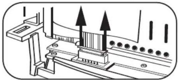
11 Unclip the ribbon cable joining the radio/climate control panel to the radio chassis. (Figure I)
12 Remove (8) Phillips screws securing the radio chassis and (6) Phillips screws securing the radio/climate control panel to the factory bracket assembly. Save screws and bracket for re-use during kit assembly.
(Figure J,K)
Continue to kit assembly.
natural_image
Technical diagram of a mechanical assembly with two upward-pointing arrows indicating motion or force direction (no text or symbols present)


ISO MOUNT RADIO PROVISION
*Note: Refer also to the instructions included with the aftermarket radio.
1 Position the radio into the factory bracket assembly and secure with the screws supplied with the aftermarket radio. (Figure A)
2 Attach the radio housing to the factory bracket assembly using the factory hardware. (Figure B)
3 Connect the black end of the climate control cable to the climate controls in the radio housing and connect the other end of the cable to the factory climate control harness during final assembly.
Continue to final assembly.

natural_image
Technical line drawing of a mechanical device with no visible text or symbols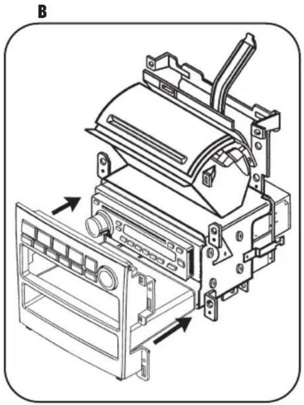
natural_image
Technical line drawing of an electronic device with internal components and mounting brackets (no text or symbols)FINAL ASSEMBLY

(A) Strip wire ends back 1/2"
B) Twist ends together
C) Solder
D) Tape
1 Locate the factory wiring harness in the dash. Metra recommends using the proper mating adapter and making connections as shown. (Isolate and individually tape off the ends of any unused wires to prevent electrical short circuit.)
2 Re-connect the negative battery terminal and test the unit for proper operation.
3 Reassemble radio and dash assemblies in reverse order of disassembly.
FINAL WIRING CONNECTIONS
Make wiring connections using the EIA color code chart shown below and the instructions included with the head unit. Metra recommends making connections as shown below; Strip, Splice, Solder, Tape. Isolate and individually tape off ends of any unused wires to prevent electrical short circuit.
METRA / EIA WIRING CODE
| 12V Ignition / Acc. . . . . . . . Red | Right Front (+) . . . . . . . . . . . . . . . . . . . . . . . . . . . . . . . . . . . . . . . . . . . . . . . . . . . . . . . . . . . . . . . . . . . . . . . . . . . . . . . . . . . . . . . . . . . . . . . . . . . . |
| 12V Batt / Memory. . . . . . . . . . . . Yellow | Right Front (-). . . . . . . . . . . . . . . . . . . . . . . . . . . . . . . . . . . . . . . . . . . . . . . . . . . . . . . . . . . . . . . . . . . . . . . . . . . . . . . . . . . . . . . . . . . . . . . . . . . . Ground. . . . . . . . . . . . . . . . . . . . . . . . . . . . . . . . . . . . . . . . . . . . . . . . . . . . . . . . . . . . . . . . . . . . . . . . . . . . . . . . . . . . . . . . . . . . . . . . . . . . Power Antenna. . . . . . . . . . . . . . . . . . . . . . . . . . . . . . . . . . . . . . . . . . . . . . Amp Turn-On. . . . . . . . . . . . . . . . . . . . . . . . . . . . . . . . . . . . . . . . Amp Ground. . . . . . . . . . . . . . . . . . . . . . . . . . . . . . . . Illumination. . . . . . . . . . . . . . . . . . . . . . . . . Dimmer. . . . . . . . . . . . . . . . . . . . . . . . . . . . . . . . . . . . . . . . . . . . . . . . . . . . . . . . . . . . . . . . . . . . . . . . . . . . . . . . . . . . . . . . . . . . . . . . . . . |
*NOTE: When a Black wire is not present, ground radio to vehicle chassis. All colors may not be present on all leads due to manufacturer's specifications.
NOTES
99-7605 INSTRUCTIONS


- INSTALLATION INSTRUCTIONS FOR PART 99-7605
- APPLICATIONS
- INFINITI G35 Coupe 2005-07
- INFINITI G35 Sedan 2005-06
- Painted And Finished To Match Factory Dash
- 99-7605
- TABLE OF CONTENTS
- Dash Disassembly
- Kit Assembly
- INFINITI G35 Coupe 2005-07 / INFINITI G35 Sedan 2005-06
- ISO MOUNT RADIO PROVISION
- FINAL ASSEMBLY
- FINAL WIRING CONNECTIONS
- NOTES
Brand : Metra
Model : 99-7605
Category : Car Installation Kit