500 Density Compressor - Audio Compressor GC Audio - Free user manual and instructions
Find the device manual for free 500 Density Compressor GC Audio in PDF.

User questions about 500 Density Compressor GC Audio
0 question about this device. Answer the ones you know or ask your own.
Ask a new question about this device
Download the instructions for your Audio Compressor in PDF format for free! Find your manual 500 Density Compressor - GC Audio and take your electronic device back in hand. On this page are published all the documents necessary for the use of your device. 500 Density Compressor by GC Audio.
USER MANUAL 500 Density Compressor GC Audio
Thank you for purchasing the Density Compressor.
We hope you have as much fun using it as we had designing it!
Warning : When you remove the module from an 500 rack, never pull on the electronic card, always pull from the front face.
The GC Audio Density compressor is a complete VCA Compressor.
The balancing and unbalancing stage consists of Lundhal transformers which remains to this day the only way to perform common mode rejection without adding distortion. The follower OPA have been chosen for optimal operation of the VCA.
Great care has been taken in the choice of capacitors. Each coupling and decoupling link is optimized for an impulse response. The low values are ensured by Wima plastics and the higher values by Long Life low ESR electrolytic.
The output balancing stage consists of a Lundhal high level Output transformer preceded by a solid low output impedance current generator stage.
The few uH generated naturally by the output coil of the transformer brings density and a feeling of proximity.
No sound goes through the front panel switches, each switch drives gold contact mechanical relays or ultra low R-On solid state relays.
The result is a responsive, quiet compressor with lots of character.
Technical data :
Threshold : -30dB / +10dB.
Ratio : 1 / 20
Attack : 0.1ms / 15ms
Release : 1.5ms / 150ms
Output gain : -20dB / +20dB
HP filter side chain : 20Hz / 200Hz
Auto time setting with « brick wall » limiter curve
Knee setting
All measurements are made with Audio Precision device, Z input = 100K Ohms :
THD + N @ max gain = 0.05%
Noise = -81 dBu @ max gain (150 Input Load - 20Hz/20Khz)
Curve :

line
| dBu | T | Blue Line | Pink Line | Red Line | |------|-------|-----------|-----------|----------| | -60 | -60 | -60 | -60 | -60 | | -55 | -55 | -55 | -55 | -55 | | -50 | -50 | -50 | -50 | -50 | | -45 | -45 | -45 | -45 | -45 | | -40 | -40 | -40 | -40 | -40 | | -35 | -35 | -35 | -35 | -35 | | -30 | -30 | -30 | -30 | -30 | | -25 | -25 | -25 | -25 | -25 | | -20 | -20 | -20 | -20 | -25 | | -15 | -15 | -15 | -15 | -25 | | -10 | -10 | -10 | -10 | -25 | | -5 | -5 | -5 | -5 | -25 | | 0 | 0 | 0 | 0 | -25 | | 5 | 5 | 5 | 5 | -25 | | 10 | 10 | 10 | 10 | -25 | | 15 | 15 | 15 | 15 | -25 | | 20 | 20 | 20 | 20 | -25 |Frequency Response :
line
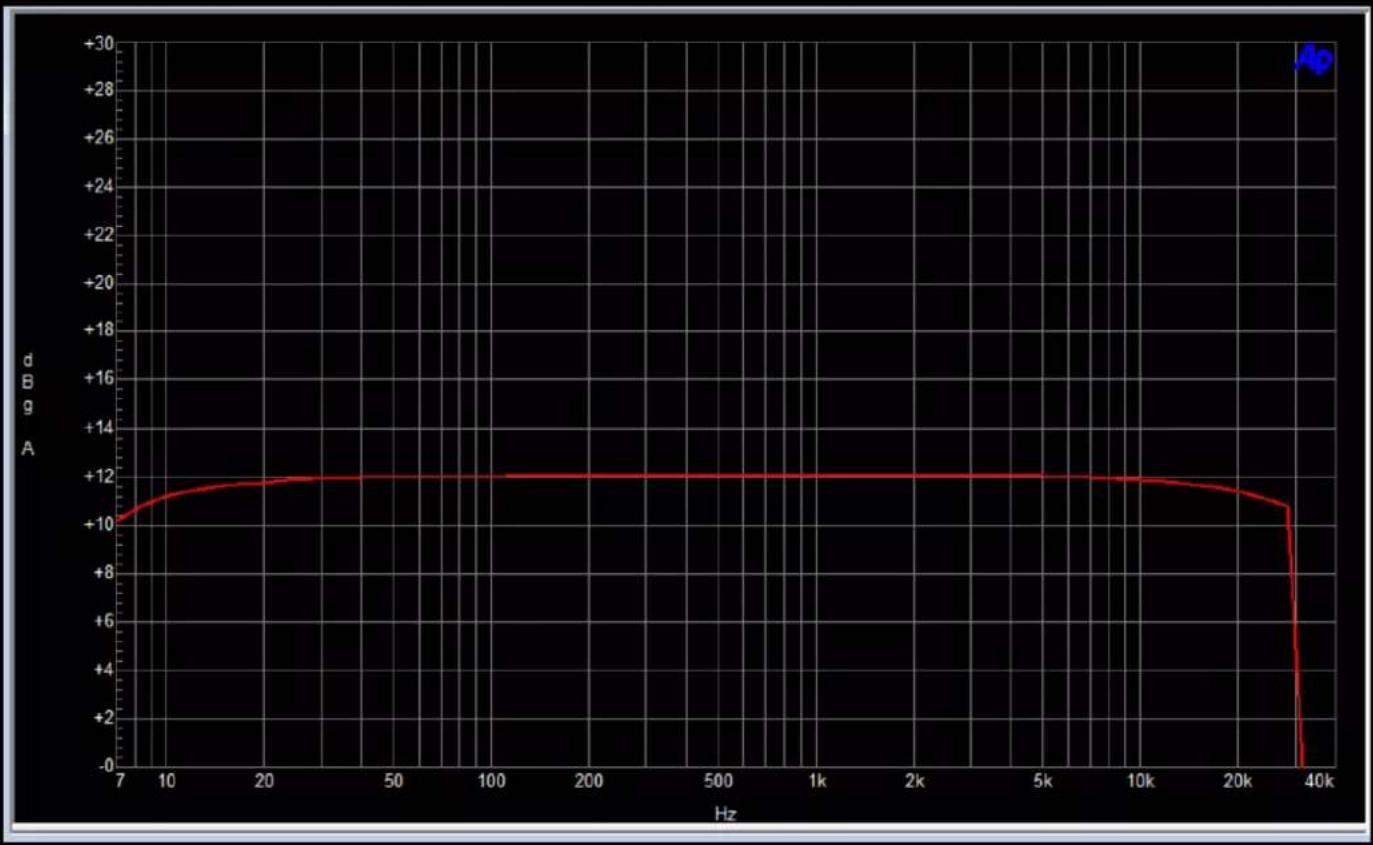
| Hz | dB/gA | | ---- | ----- | | 7 | +10 | | 10 | +11 | | 20 | +12 | | 50 | +12 | | 100 | +12 | | 200 | +12 | | 500 | +12 | | 1k | +12 | | 2k | +12 | | 5k | +12 | | 10k | +12 | | 20k | +11 | | 35k | -1 | | 40k | -3 |Phase:
line
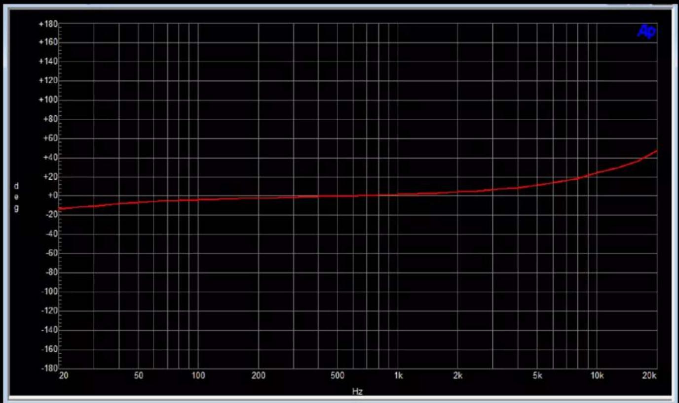
| Hz | deg | | ---- | ---- | | 20 | -18 | | 50 | -16 | | 100 | -14 | | 200 | -12 | | 500 | -10 | | 1k | -8 | | 2k | -6 | | 5k | -4 | | 10k | -2 | | 20k | 0 |Curve with Side Chain Filter :
(Red without side chain, Yellow @ 100hz, Blue @ 200hz.)

line
| dBu | Blue Line | Yellow Line | Red Line | |------|-----------|-------------|----------| | -60 | -60 | -60 | -60 | | -55 | -55 | -55 | -55 | | -50 | -50 | -50 | -50 | | -45 | -45 | -45 | -45 | | -40 | -40 | -40 | -40 | | -35 | -35 | -35 | -35 | | -30 | -30 | -30 | -30 | | -25 | -25 | -25 | -25 | | -20 | -20 | -20 | -25 | | -15 | -15 | -15 | -25 | | -10 | -15 | -15 | -25 | | -5 | -15 | -15 | -25 | | +0 | -15 | -15 | -25 | | +5 | -15 | -15 | -25 |Noise @ gain Max :
