Analog Riser - Audio GC Audio - Free user manual and instructions
Find the device manual for free Analog Riser GC Audio in PDF.

User questions about Analog Riser GC Audio
0 question about this device. Answer the ones you know or ask your own.
Ask a new question about this device
Download the instructions for your Audio in PDF format for free! Find your manual Analog Riser - GC Audio and take your electronic device back in hand. On this page are published all the documents necessary for the use of your device. Analog Riser by GC Audio.
USER MANUAL Analog Riser GC Audio
Thank you for purchasing the GC Audio Analgo Riser. We hope you enjoy using it as much as we enjoyed designing it!
text_image
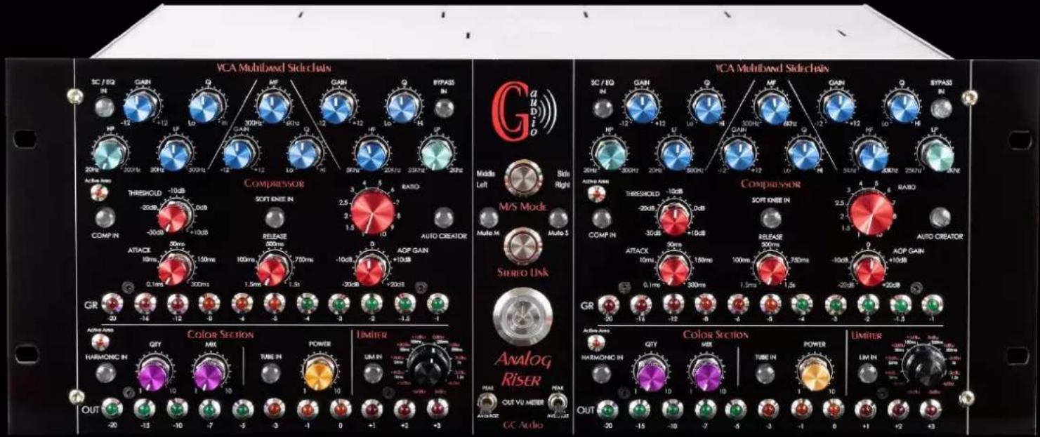
VCA Multibased SideChain SC / EQ IN GAIN Q MF GAIN Q BYPASS IN HP -12 -12 LF 300Hz 30Hz LO -12 -12 Lo -12 LF 50Hz 20Hz 250Hz 25Hz 20Hz 20Hz 20Hz 20Hz 20Hz 20Hz 20Hz 20Hz 20Hz 20Hz 20Hz 20Hz 20Hz 20Hz 20Hz 20Hz 20Hz 20Hz 20Hz 20Hz 20Hz 20Hz 20Hz 20Hz 20Hz 25Hz Audio Left Side Right Audio Mode THRESHOLD -10dB -20dB 0dB -30dB +10dB COMP IN 30ms ATTACX 18ms 150ms 100ms 750ms 1.5ms 1.5s 1.5s 1.5s 1.5s 1.5s 1.5s 1.5s 1.5s 1.5s 1.5s 1.5s 1.5s 1.5s 1.5s 1.5s 1.5s 1.5s 1.5s 1.5s 1.5s 1.5S Multi M- Audio Creator AOP GAIN +10dB -20dB +20dB GR -30 -16 -12 6 -4 -5 -4 -3 -2 -1.5 -1 Color Section HARMONIC IN QTY MIX TUBE IN POWER LIMIER UBA IN OUT VU MEER CC Audio AVGND OUT -20 -13 -10 -7 -5 -3 -1 0 +1 +2 +3 VCA Multibased SideChain SC / EQ IN GAIN Q MF GAIN Q BYPASS IN HP -12 -12 LF 300Hz 30Hz 60Hz Q -12 +12 LF 30Hz 20Hz 250Hz 25Hz HP -12 +12 LO -4R -3D+3C+6C+9C Q -12 +12 LO 30Hz 20Hz 250Hz 25Hz AMP IN 30MHz 30MHz 30MHz 30MHz 30MHz 30MHz 30MHz 30MHz 30MHz 30MHz 30MHz 30MHz 30MHz 30MHz 30MHz 30MHz 30MHz 30MHz 30MHz 30MHz 30MHz 30MHz 30MHz 30MHz 30MHz 30kHz Audio Mode: THRESHOLD -10dB -20dB 0dB -30dB +10dB COMP IN 30ms + ATTACX 18ms +15ms +75ms +75ms +75ms +75ms +75ms +75ms +75ms +75ms +75ms +75ms +75ms +75ms +75ms +75ms +75ms +75ms +75ms +75ms +75ms +75ms +75ms +75ms +75ms +75ms +75ms +TROCKE IN RATIO: -30dB -30dB -30dB -30dB -30dB -30dB -30dB -30dB -30dB -30dB -30dB -30dB -30dB -30dB -30dB -30dB -30dB -30dB -30dB -30dB -30dB -30dB -30dB -30dB -30dB -30dB - AUTO VU MEER CC Audio AVGND OUT VU MEER CC Audio Color Section: HARMONIC IN QTY MIX TUBE IN POWER LIMIER UBA IN OUT VU MEER CC Audio AVGND OUT VU MEER CC AudioThe GC Audio Analog Riser is a high-end dynamics and harmonics processor, which allows you to obtain sharp and unique dynamics and harmonics processing. It offers a unique sound signature for demanding engineers, right up to the mastering stage.
Several years of research and development have been necessary to create this analog processor so that it can be used in all areas of the audio business.
An uncompromising electronic design has been made to obtain an irreproachable sound quality.
The GC Audio Analog Riser will allow you to process sound with confidence and pleasure for recording, mixing and mastering.
The Analog Riser is a fully analog design built around 5 tubes, 4 VCAs, 4 Lundhal transformers, a hundred low noise operational amplifiers, Grayhill switches, IP knobs, etc. Its powerful combinations of harmonic processing / make up and MS mode make it a unique machine.
No signal goes through the front panel switches. About 40 relays ensure a routing as close as possible to the motherboard.
Each functions is trimmed in factory in order to have the best matching between left and right.
Technical Data:
1) Equalizer stage:
➢ High pass 12 dB / octave, 20hz to 300hz.
Low pass 12 dB / octave, 250hz to 20khz.
Low frequency 20hz to 500hz, gain -12dB to + 12dB, variable Q.
Medium frequency 300hz to 6khz, gain -12dB to + 12dB, variable Q.
High frequency 5khz to 20khz, gain -12dB to + 12dB, variable Q.
2) Compressor stage:
Threshold -30dB to +10dB
Ratio 12 steps, 1.5 to 10.
Attack 0.5ms to 300ms.
Release 1.5ms to 1.5s
Make up -20dB to +20dB
Knee setting (Soft / Hard)
Auto creator setting (automatic fast Attack and Release for transcient).
3) Harmonic Stage:
Harmonic generator.
Harmonic mix density.
4) Tube Stage:
Gain 0dB to 20 dB.
4 stages of 12AY7 tubes on each channel.
High voltage power supply with EZ81 bridge.
5) Brickwall limiter stage.
➢ Fixed ultra fast attack trimmed in factory.
12 steps threshold +6dBu to +5dBu.
8 steps release 10ms to 1.5s.
Typical curve limiter:

line
| dBu | u (Line 1) | u (Line 2) | u (Line 3) | u (Line 4) | u (Line 5) | u (Line 6) | u (Line 7) | u (Line 8) | u (Line 9) | |------|------------|------------|------------|------------|------------|------------|------------|------------|------------| | -8 | -6.0 | -6.0 | -6.0 | -6.0 | -6.0 | -6.0 | -6.0 | -6.0 | -6.0 | | -7 | -5.0 | -5.0 | -5.0 | -5.0 | -5.0 | -5.0 | -5.0 | -5.0 | -5.0 | | -6 | -4.0 | -4.0 | -4.0 | -4.0 | -4.0 | -4.0 | -4.0 | -4.0 | -4.0 | | -5 | -3.0 | -3.0 | -3.0 | -3.0 | -3.0 | -3.0 | -3.0 | -3.0 | -3.0 | | -4 | -2.0 | -2.0 | -2.0 | -2.0 | -2.0 | -2.0 | -2.0 | -2.0 | -2.0 | | -3 | -1.0 | -1.0 | -1.0 | -1.0 | -1.0 | -1.0 | -1.0 | -1.0 | -1.0 | | -2 | 0.0 | 0.0 | 0.0 | 0.0 | 0.0 | 0.0 | 0.0 | 0.0 | 0.0 | | -1 | 1.0 | 1.0 | 1.0 | 1.0 | 1.0 | 1.0 | 1.0 | 1.0 | 1.0 | | 0 | 2.0 | 2.0 | 2.0 | 2.0 | 2.0 | 2.0 | 2.0 | 2.0 | 2.0 | | +1 | 3.0 | 3.0 | 3.0 | 3.0 | 3.0 | 3.0 | 3.0 | 3.0 | 3.0 | | +2 | 4.0 | 4.0 | 4.0 | 4.0 | 4.0 | 4.0 | 4.0 | 4.0 | 4.0 | | +3 | 5.0 | 5.0 | 5.0 | 5.0 | 5.0 | 5.0 | 5.0 | 5.0 | 5.0 | | +4 | 6.0 | 6.0 | 6.0 | 6.0 | 6.0 | 6.0 | 6.0 | 6.0 | 6.0 | | +5 | 6.0 | 6.0 | 6.0 | 6.0 | 6.0 | 6.0 | 6.0 | 6.0 | 6.0 | | +6 | 6.0 | 6.0 | 6.0 | 6.0 | 6.0 | 6.0 | 6.0 | 6.0 | 6.0 |The Analog Riser offers 5 processing stages in one machine:
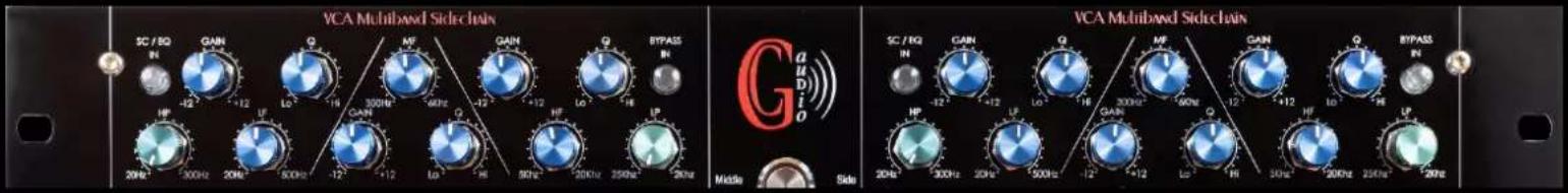
1) A 3-band full parametric equalizer with Low Cut and High Cut:
text_image
VCA Multiband Side chain SC / 50Ω IN -12° 300Hz 20Hz GAIN Q Lo +12 300Hz -12° GAIN Q Lo +12 300Hz -12° GAIN Q Lo +12 300Hz -12° GAIN Q Lo +12 300Hz -12° GAIN Q Lo +12 300Hz -12° GAIN Q Lo +12 300MHz -12° GAIN Q Lo +12 300MHz -12° GAIN Q Lo +12 300MHz -12° GAIN Q Lo +12 300MHz -12° GAIN Q Lo +12 300MHz -12° GAIN Q Lo +11.5m² -12° GAIN Q Lo +11.5m² -12° GAIN Q Lo +11.5m² -12° GAIN Q Lo +11.5m² -12° GAIN Q Lo +11.5m²Although the primary function of this EQ is to define a multiband contour for the compressor detection threshold, it can also be used as a stand-alone EQ.
In Sidechain mode (compressor stage on), it has a narrow bandwidth for optimal VCA stability. The use of the equalizer in insert in the compressor sidechain allows to realize very precise dynamic treatments. Indeed, to avoid a compression "pumping", a Low Cut is often used in the Sidechain to discriminate for example, the bass drum. Unfortunately this does not only discriminate the bass drum but the whole low end of the spectrum. With the multiband contour you can first find the exact frequency of the bass drum and only separate this frequency at the level of the compressor's release threshold.
In the opposite case, which may be desired for electro music for example, you can turn up the gain only on the bass drum frequency which will give you a stable pumping with a good rhythmic behavior. More globally, the multiband VCA contour will allow you to compress at different thresholds the pleasant and the unpleasant frequencies.
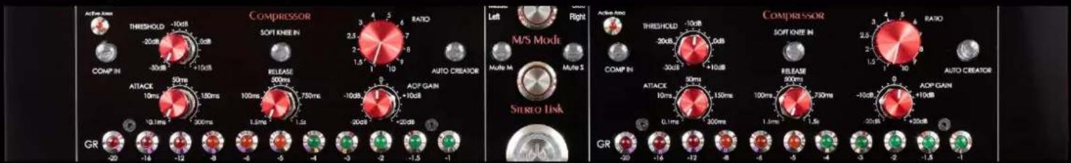
2) A full VCA compressor:
text_image
Action Arm THRESHOLD -10dB -20dB 1.0dB COMP IN -30dB +10dB COMP IN ATLACK 50ms 10ms 150ms 1.0ms 300ms GR -20 -16 -12 -8 -5 -4 -3 -2 -1.5 -1 COMPRESSOR SOFT KNEE IN RELEASE 500ms 100ms 750ms 1.5ms 1.5s -10dB 9 -20dB -20dB Ratio 2.5 7 2.5 8 1.5 10 Auto CREATOR AOP GAIN +10dB -20dB -20dB Left M/S Mode Right Multi M Multi S Stereo Link Active Arm THRESHOLD -10dB -20dB 1.0dB COMP IN -30dB +10dB RELEASE 500ms 100ms 750ms 1.5ms 1.5s -10dB 9 -20dB -20dB Ratio 2.5 7 2.5 8 1.5 10 Auto CREATOR AOP GAIN +10dB -20dB -20dB GR -20 -16 -12 -8 -5 -4 -3 -2 -1.5 -1This compressor is built around a state-of-the-art VCA and features full adjustment of the Time, Threshold and Make Up components. With impeccable characteristics in terms of signal to noise ratio and distortion, it is particularly stable.
Note that it is equipped with a new and original function: "Auto Creator". In this mode, the Attack and Release are automatic. They will be globally fast but vary according to the speed of the input signal. The times will be different depending on the nature of the signal: transient or constant signal. This is a very interesting function on percussive sources or bass.
3) A Harmonic treatment stage :

text_image
Color Sceitic HARMONIC IN QTY 10 1 10 OUT -20 -13 -10 -7 -5 LAMBIC EN-IN ANALOG RISER FLEX OUT VU METER AVIANCE G.C. Audio Color Sceitic HARMONIC IN QTY 10 1 10 OUT -20 -13 -10 -7 -5 LAMBIC EN-INThis stage generates odd harmonics. It is possible to define the amount of harmonics generated as well as the density integrated in the original signal. The electronic design has been optimized so that this function adds a proximity presence to the signal, thus treating more the top of the spectrum.
4) A full tube gain stage :

text_image
ON TUBE IN POWER 10 5 -3 -1 0 ANALOG RISER OUT VU METER AVERAGE GC Audio ON TUBE IN POWER 10 5 -3 -1 0 1 -3 -1 0The spirit of this tube stage is to extract the full essence of the vacuum tube character. Each channel consists of four 12AY7 lamp stages. A high voltage EZ81 tube power supply is also present and offers a high quality choke filtering system allowing a very low residual ripple. The lamp power supply also allows for a gradual rise in high voltage, which preserves the life of the 12AY7 lamps.
The Analog Riser allows two types of make up: The discrete make up of the compressor stage which will have a very transparent rendering and the lamp make up which allows to color the signal, or even give it a saturation.
To use the maximum potential of the headroom of the tube stage, it is interesting to reduce the make up of the compressor stage beforehand.
5) A Brickwall type Limiter:

text_image
LIMITER LIM N +1 +2 +3 Analog RISER 70k OUT VUMBER AVGAGE AVGAGE GC Audio LIMITER LIM N +1 +2 +3 -5.0V 1.0V 1.0V 1.0V -5.0V 1.0V 1.0V 1.0V -5.0V 1.0V 1.0V 1.0V +1 +2 +3The last output stage of the Analog Riser is a Brickwall Limiter with 12 Threshold positions. To avoid saturating your converters, the optimal setting is +4dBu, which will give you 0dBfs at the input of your DAW.
Each position is factory set to a negative tolerance. For example, the +ddBu position will have a real level of -0.00 dBfs, which ensures no digital saturation.
The Limiter does not defy the laws of physics, but by pushing the Make Up to its limits, the dynamic range will be reduced and the overall volume impression can increase considerably without exceeding +4dBU (0db VU).
The Analog Riser has 3 operating modes:
1) Mode Dual Mono
Configuration A: All stages are active.

text_image
In Left VCA Multiband Sidechain In Right Compressor Eq insert in sidechain Audio Middle Left M/S Mod Side Right VCA Multiband Sidechain COMpressor Eq insert in sidechain Stereo Link Color Section Out Left Analog Riser Out Right OUT OUT VU METER GC AudioThis is the default mode when you power on the. An analog processor with two completely independent channels. In this mode, you can simultaneously process two tracks independently. As the device has many functions, it is necessary to understand its routing, which prioritizes dynamic processing above all. Please consider the following diagrams:
Configuration A: When all stages are on, the machine offers the following functions in order from top to bottom: Multi-band sidechain stage with LPF and HPF > VCA compressor > Harmonic > Tube > Limiter
Configuration B: When all stages are active but the Compressor stage:

text_image
In Left VCA Multibewd Side Chain In Right SC / IQ IN GAIN Q HF GAIN Q BYPASS IN HP -12 +12 LO 10 300Hz 8kHz -12 +12 LO 10 300Hz 70kHz 20Hz 20Hz 20Hz 20Hz 20Hz 20Hz 20Hz 20Hz 20Hz 20Hz 20Hz 20Hz 20Hz 20Hz 20Hz 20Hz 20Hz 20Hz 20Hz 20Hz 20Hz 20Hz 20Hz 20Hz 20Hz 20kHz 20kHz 20kHz 20kHz 20kHz 20kHz 20kHz 20kHz 20kHz 20kHz 20kHz 20kHz 20kHz 20kHz 20kHz 20kHz 20kHz 20kHz 20kHz 20kHz 20kHz 20kHz 20kHz 20kHz 20kHz 20kΩ 300Hz 20kΩ 500Hz -12 -12 -12 -12 -12 -12 -12 -12 -12 -12 -12 -12 -12 -12 -12 -12 -12 -12 -12 -12 -12 -12 -12 -12 -12 -12 -12 -12 -12 -12 -12 -12 -12 -12 - Active Area Threshold -10dB -20dB 7.5dB 6.5dB 4.5dB 3.5dB 3.5dB 3.5dB 3.5dB 3.5dB 3.5dB 3.5dB 3.5dB 3.5dB 3.5dB 3.5dB 3.5dB 3.5dB 3.5dB 3.5dB 3.5dB 3.5dB 3.5dB 3.5dB 3.5dB 4mS Mod. COMP IN COMP IN AUTO CREATOR ATTACK 50ms 100ms 750ms -10dB AOP GAIN +10dB AOP GAIN +10dB AOP GAIN +10dB AOP GAIN +10dB AOP GAIN +10dB AOP GAIN +10dB AOP GAIN +10dB AOP GAIN +10dB AOP GAIN +10dB AOP GAIN +10dB AOP GAIN +10dB AOP GAIN +10dB AOP GAIN +10dB C Mio Mode Control SMO Section Limiter CG Audio Color Section Limiter GC Audio Color Section Out Left Out Right Out Right2) Stereo Mode:
After turning on the machine, press the "STEREO LINK" button.
This mode is dedicated to stereo BUS compression.
The BUS compression being generally positioned on moderate ratios, it has been chosen a L+R summation for the Sidechain input. The limiter works on a ratio of +Infinite, it has no summation on the sidechain input in order to keep a faithful stereo image. A common Threshold, calibrated from factory, allows a precise adjustment between L and R. Also a Link of the VCA time control allows an identical behavior.
In this mode, all control knobs are linked to obtain a very precise and identical adjustment between Left and Right.
An "Active zone area" LED allows you to define the zones whose knobs are functional.
Although the potentiometers are linked, the functions of both channels work and to activate a function, it is therefore necessary to switch it on the left channel and on the right channel.
As the machine has many functions, it is necessary to understand its routing which prioritizes above all the dynamic processing. Please consider the following synoptic:
Configuration A : When all stages are active

text_image
In Left Sum L+R In Right VCA Multiband Sidechain Compressor SOFT KNEIN Ratio Eq insert in sidechain M/S Modi Stereo Ink Color Section Lumber Analog Riser Out Left Out Right True L/R with one knob SC / EQ IN CJAM Q MF GAIN Q BYPASS IN UP -12 -12 LO 30kHz M/FN -12 -12 LO -14 50Hz 20kHz 50Hz 20Hz 20Hz 30Hz 30Hz 30Hz 30Hz 30Hz 30Hz 30Hz 30Hz 30Hz 30Hz 30Hz 30Hz 30Hz 30Hz 30Hz 30Hz 30Hz 30Hz 30Hz 30Hz 30Hz 30Hz 30Hz 30Hz 30Hz SC / EQ IN CAIN Q MF GAIN Q BYPASS IN UP -12 -12 LO 30kHz M/FN -12 -12 LO -14 50Hz 20kHz 50kHz 20Hz 20Hz 30Hz 30Hz 30Hz 30Hz 30Hz 30Hz 30Hz 30Hz 30Hz 30Hz 30Hz 30Hz 30Hz 30Hz 30Hz 30Hz 30Hz 30Hz 30Hz 30Hz 30Hz 30Hz 30kHz 20kHz 20kHz 20kHz 20kHz 20kHz 20kHz 20kHz 20kHz 20kHz 20kHz 20kHz 20kHz 20kHz 20kHz 20kHz 20kHz 20kHz 20kHz 20kHz 20kHz 20kHz 20kHz 20kHz 20kHz 20kHz 19.5mV 18.5mV 17.5mV 16.5mV 15.5mV 14.5mV 13.5mV 12.5mV 11.5mV 10.5mV 9.5mV 8.5mV 7.5mV 6.5mV 5.5mV 4.5mV 3.5mV 2.5mV 1.5mV 0.5mV 9.5mV 8.5mV 7.5mV 6.5mV 5.5mV 4.5mV 3.5mV 2.5mV 1.5mV 0.5mV 9.5mV 8.5mV 7.5mV 6.5mV 5.5mV 4.5nV 3.5nV 2.5nV 1.5nV 9.5nV 8.5nV 7.5nV 6.5nV 5.5nV 4.5nV 3.5nV 2.5nV 1.5nV 9.5nV 8.5nV 7.5nV 6.5nV 5.5nV 4.5nV 3.5nV 2.5nV 1.5nV 9.5nV 8.5nV 7.5nV 6,4,4,4,4,4,4,4,4,4,4,4,4,4,4,4,4,4,4,4,4,4,4,4,4,4,4,4,4,4,4,4,4,4,4,4,4,4,4,4,4,4,4,4,4,4,4,4,4,4,4,8Note that in this configuration, it is sufficient to deactivate the compressor for monitoring the sidechain contour.
In stereo mode, it is not possible to have a stereo equalizer, this one being exclusively dedicated to the stereo compression contour.
3) M/S Mode (Mid/Side)
To activate this mode, after powering up the machine, simply press the "M/S" button. This mode dedicated to mastering is a very powerful tool that allows a different dynamic treatment between what is mixed in the center (Mid) and what is mixed on the sides (Side).
The M/S encoder and decoder of the Analog Riser are built around dedicated differential amplifiers with laser-etched calibration, which allows for the most precise signal processing. This mode remains completely analog, without A/D - D/A conversion.
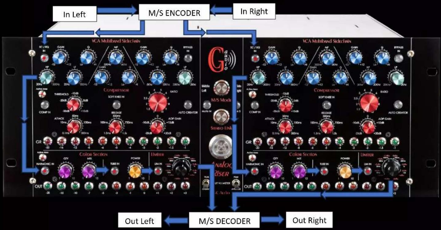
Configuration A: All stages activated. The left channel controls the signal in the middle, and the right channel controls the signal on the sides:

text_image
In Left M/S ENCODER In Right VCA Multibased Sidechain SC/ROQ IN CASH Q MF GAIN Q BYPASS IN HP LP 300Hz 60Hz 12+12 HF 300Hz 280Hz 290Hz 20Hz 300Hz 20Hz 300Hz 12-12-12 H4 50Hz 300Hz 280Hz 290Hz Active areas COMP IN THRESHOLD -10dB -20dB 1.5ms -30dB -10dB ATTACK 50ms 10ms 1.5ms 300ms 1.5ms 1.5ms 1.5ms -1.5-1 GR Color Section MAX TUBE IN POWER LIMETER LM IN OUT -20 -15 -10 -7 -5 -3 -1 0 +1 +2 +3 Out Left M/S DECODER Out Right VCA Multibased Sidechain SC/ROQ IN GAIN Q HF NF GAIN Q BYPASS IN HP LP 300Hz 60Hz 12+12 HF 300Hz 280Hz 290Hz 20Hz 300Hz 20Hz 300Hz 12-12-12 H4 50Hz 300Hz 280Hz 290Hz Middle Left M/S Mode Multi M Audio S COMPRESSION SOFT KNEE IN COMP IN THRESHOLD -10dB -20dB 1.5ms -30dB -10dB -30dB -1.5ms -30dB -2.5ms -30dB -4.5ms -4.5-5.5ms -4.5-6.5ms -4.5-7.5ms -4.5-8.5ms -4.5-9.5ms -4.5-1.5ms -4.5-2.5ms -4.5-3.5ms -4.5-4.5ms -4.5-5.5ms -4.5-6.5ms -4.5-7.5ms -4.5-8.5ms -4.5-9.5ms -4.5-1.5ms GR Color Section MAX TUBE IN POWER LIMETER C Audio OUT -20 -15 -10 -7 -5 -3 -1 0 +1 +2 +3 Out Left M/S DECODER Out RightConfiguration B : When all stages are active but the Compressor stage :
flowchart
graph TD
    A["In Left"] --> B["M/S ENCODER"]
    B --> C["In Right"]
    D["VCA Multibased Side chains"] --> E["Compressor"]
    E --> F["Audio Creator"]
    G["AVIO"] --> H["AVIO"]
    I["AVIO"] --> J["AVIO"]
    K["AVIO"] --> L["AVIO"]
    M["AVIO"] --> N["AVIO"]
    O["AVIO"] --> P["AVIO"]
    Q["AVIO"] --> R["AVIO"]
    S["AVIO"] --> T["AVIO"]
    U["AVIO"] --> V["AVIO"]
    W["AVIO"] --> X["AVIO"]
    Y["AVIO"] --> Z["AVIO"]
    AA["AVIO"] --> AB["AVIO"]
    AC["AVIO"] --> AD["AVIO"]
    AE["AVIO"] --> AF["AVIO"]
    AG["AVIO"] --> AH["AVIO"]
    AI["AVIO"] --> AJ["AVIO"]
    AK["AVIO"] --> AL["AVIO"]
    AM["AVIO"] --> AN["AVIO"]
    AO["AVIO"] --> AP["AVIO"]
    AQ["AVIO"] --> AR["AVIO"]
    AS["AVIO"] --> AT["AVIO"]
    AU["AVIO"] --> AV["AVIO"]
    AW["AVIO"] --> AX["AVIO"]
    AY["AC Audio"] --> AZ["Color Section"]
    AZ --> BA["TUBE IN"]
    BA --> BB["POWER"]
    BB --> BC["LIMIN IN"]
    BC --> BD["LIMIN IN"]
    BE --> BEA["FEAM"]
    BEB --> BEF["AVIO"]
    BF --> BFAN["AVIO"]
    BG["AVIO"] --> BH["AVIO"]
    BI["AVIO"] --> BJ["AVIO"]
    BK["AVIO"] --> BL["AVIO"]
    BM["AVIO"] --> BN["AVIO"]
    BO["AVIO"] --> BP["AVIO"]
    BQ["AVIO"] --> BQAF["AVIO"]
    BR["AVIO"] --> BR["AVIO"]
    BS["AVIO"] --> BS["AVIO"]
    BT["AVIO"] --> BTAF["AVIO"]
    BU["AVIO"] --> BUAF["AVIO"]
    BV["AVIO"] --> BVAF["AVIO"]
    BW["AVIO"] --> BWAF["AVIO"]
    BX["AVIO"] --> BYA["AVIO"]
    CA["AVIO"] --> CAAF["AVIO"]
    CB["AVIO"] --> CBAF["AVIO"]
    CC["AVIO"] --> CCAF["AVIO"]
    DD["AVIO"] --> DDAF["AVIO"]
    DB["AVIO"] --> DBAF["AVIO"]
    DC["AVIO"] --> DCAF["AVIO"]
The M/S function of the Analog Riser is very powerful. It allows new settings where it will be possible for example to make-up the tube gain on the sides and a discreet make-up on the middle. The same goes for all other functions. In this mode, a large number of sound configurations are possible.
TECHNICAL OVERVIEW
The Analog Riser has 3 operation modes
1) Dual Mono Mode:
This is the default mode when you turn on the machine. It is a completely independent two channel analog processor. It is possible in this mode to simultaneously process two separate tracks in a mix.
As the device has many functions, it is necessary to understand its routing, which prioritizes dynamic processing above all. Please consider the following synoptic.
Configuration A : When all stages are active

flowchart
graph LR
    A["In"] --> B["Compressor"]
    C["Equalizer"] --> D["In Sidechain compressor"]
    B --> E["Harmonic"]
    D --> E
    E --> F["Tube"]
    F --> G["Limiter"]
    G --> H["Out"]
Configuration B : When all stages are active but the Compressor stage

flowchart
graph LR
    A["In"] --> B["Equalizer"]
    B --> C["Harmonic"]
    C --> D["Tube"]
    D --> E["Limiter"]
    E --> F["Out"]
2) Stereo Mode:
After switching on the machine, you just have to press the "Stereo" button. This mode is dedicated to the compression of stereo BUSSES.
The bus compression being generally positioned on moderate ratios, it was chosen a L+R summation for the Side Chain input.
As the limiter works on a ratio of +infinity, it does not have any summation on the input of its side chain in order to keep a faithful stereo image. A common threshold, calibrated from the factory, allows a precise adjustment between L and R. Also a link of the VCA time control allows an identical behavior.
In this mode, all the control knobs are linked to obtain a very precise and identical adjustment between the Left and the Right channels.
An "Active zone area" LED allows to define the zones whose potentiometers are functional.
Although the potentiometers are linked, the functions of the two channels work and to activate a function, it is necessary to switch it on both left and right sections.
The device having many functions, it is necessary to understand its routing which prioritizes above all the dynamic processing. Please consider the following synoptic:
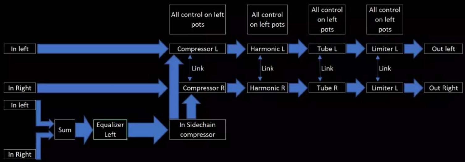
Configuration A : When all the are active
flowchart
graph TD
    A["In left"] --> B["Compressor L"]
    C["In Right"] --> D["Compressor R"]
    E["In Left"] --> F["Sum"]
    G["In Right"] --> H["Equalizer Left"]
    B <--> I["Harmonic L"]
    D <--> J["Harmonic R"]
    I <--> K["Tube L"]
    J <--> L["Tube R"]
    K <--> M["Limiter L"]
    L <--> N["Limiter L"]
    M <--> O["Out left"]
    N <--> P["Out Right"]
    B <--> Q["All control on left pots"]
    D <--> R["All control on left pots"]
    J <--> S["All control on left pots"]
    K <--> T["All control on left pots"]
    L <--> U["All control on left pots"]
    M <--> V["All control on left pots"]
    N <--> W["All control on left pots"]
    B <--> X["In Sidechain compressor"]
    D <--> X
    J <--> X
    K <--> X
    L <--> X
    M <--> X
    N <--> X
Note that in this configuration, you only need to switch off the compressor to monitor the sidechain contour.
In stereo mode, it is not possible to have a stereo equalizer, this one being exclusively dedicated to the stereo compression contour.
3) The M/S (Middle/Side) mode:
After switching on the machine, just press the "M/S" button.
This mode dedicated to mastering is a very powerful tool that allows a different dynamic treatment between what is mixed in the middle and what is mixed on the sides.
The M/S encoder and decoder of the Analog Riser is built around dedicated differential amplifiers with a laser engraved calibration which allows a very precise processing of the signal.
This mode remains completely analog, without A/D - D/A conversion.
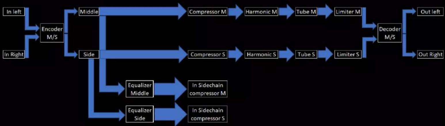
Configuration A : When all the stages are ON
flowchart
graph TD
    A["In left"] --> B["Encoder M/S"]
    C["In Right"] --> B
    B --> D["Middle"]
    B --> E["Side"]
    D --> F["Compressor M"]
    D --> G["Compressor S"]
    F --> H["Harmonic M"]
    G --> I["Harmonic S"]
    H --> J["Tube M"]
    I --> K["Tube S"]
    J --> L["Limiter M"]
    K --> M["Limiter S"]
    L --> N["Decoder M/S"]
    M --> N
    N --> O["Out left"]
    N --> P["Out Right"]
    E --> Q["Equalizer Middle"]
    E --> R["Equalizer Side"]
    Q --> S["In Sidechain compressor M"]
    R --> T["In Sidechain compressor S"]
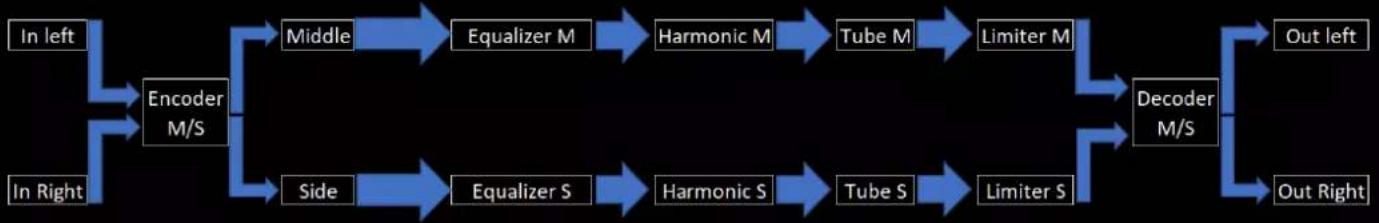
Configuration B: When all stages are ON but the Compressor stage
flowchart
graph LR
    A["In left"] --> B["Encoder M/S"]
    C["In Right"] --> B
    B --> D["Middle"]
    B --> E["Side"]
    D --> F["Equalizer M"]
    E --> G["Equalizer S"]
    F --> H["Harmonic M"]
    G --> I["Harmonic S"]
    H --> J["Tube M"]
    I --> K["Tube S"]
    J --> L["Limiter M"]
    K --> M["Limiter S"]
    L --> N["Decoder M/S"]
    M --> N
    N --> O["Out left"]
    N --> P["Out Right"]
The M/S function of the Analog Riser is very powerful. It will allow you to make new settings where it will be possible for example to make a lamp Make Up on the sides and a discreet Make Up on the middle. The same goes for all the other functions. In this mode, a large number of sound configurations are possible.
Position
This device is designed and tested to minimize internal electromagnetic emissions and provide immunity to external electromagnetic fields. To reduce the risk of performance degradation due to external interference, do not place this device near strong magnetic field sources such as power supplies, power amplifiers, speakers, etc.
Rack Mounting
The unit is designed to be rack mounted to preserve the front panel finish. The front panel graphic layer is printed below the surface to provide a rugged, durable surface designed to last the life of the product in virtually any operating environment. Failure to use the provided fasteners may damage the faceplate surface, which may void the warranty. It is recommended that additional side brackets be used for rack mounting along with the front panel fasteners, especially when the unit is mounted in a case or vehicle where vibration and transport shock are to be expected.
Maintenance
The product should be cleaned with a soft brush around the controls. If the front panel is dirty, use a damp cloth with a little household soap to remove the dirt. Do not use any solvent-based cleaners, as this could permanently damage the front panel and void the warranty!
Audio Connections
Two 3-pin XLR connectors are provided at the back panel. The inputs are female, the outputs are male connectors. All connectors follow the European wiring convention: Pin 1 = Ground, Pin 2 = Hot (+) Pin 3 = Cold.
Power
The GC Audio Analog Riser can be powered from either a 230V or 115V source via a switch on the rear panel. Please refer to the safety instructions.