PLCMDVR72 - Camera Pyle - Free user manual and instructions
Find the device manual for free PLCMDVR72 Pyle in PDF.

| Product Type | Vehicle Camera System with Monitor and DVR Recorders |
| Brand | Pyle |
| Model | PLCMDVR72 |
| Monitor Size | 7 inches |
| Display Type | Quad view (4-channel video input) |
| Included Cameras | 1 super slim license plate backup camera |
| Included Recorders | 2 mini DVR recorders (without cameras; require external cameras) |
| Storage | TF card (microSD), Class 10 recommended (not included) |
| Power Supply | 12V DC (red/black power wires) |
| Reverse Trigger | Green wire, priority on CH1 |
| Video Inputs | 4 channels via RCA jacks (2 yellow, 1 red, 1 white) |
| Monitor Functions | Mode switching (V1/V2), image left/right reverse, menu for color/brightness, volume control via remote |
| Remote Control | Yes, included |
| Mounting | Stand mount with metal buckle, adjustable tilt and height, clamp knobs |
| Installation | Professional installation recommended; avoid interfering with vehicle safety features |
| Safety | Do not watch videos while driving; no user-serviceable parts |
| Package Contents | 7" quad monitor, 2 mini DVRs, 1 backup camera, remote control, power cables, mounting hardware, user manual |
| Dimensions (Monitor, approx.) | 7.5 x 5 x 1 inches |
| Weight (Monitor, approx.) | 1.5 lbs |
| Warranty | 1 year (typical) |
| Color | Black |
Frequently Asked Questions - PLCMDVR72 Pyle
User questions about PLCMDVR72 Pyle
0 question about this device. Answer the ones you know or ask your own.
Ask a new question about this device
Download the instructions for your Camera in PDF format for free! Find your manual PLCMDVR72 - Pyle and take your electronic device back in hand. On this page are published all the documents necessary for the use of your device. PLCMDVR72 by Pyle.
USER MANUAL PLCMDVR72 Pyle
natural_image
Medical device display showing navigation screens, a black tool handle, and two camera modules (no visible text or symbols)Please read instructions carefully before installation and use. Installation should be performed by a professional installer. To ensure your safety, the driver should not watch videos or operate features on the monitor while driving. There are noserviceable parts in this unit, do not disassemble or try to repair this unit. If the unit malfunctions please return to your vendor or send to a Pyle repair facility. Please observe and obey the local laws and regulations when installing the unit.
Upon Installation, please make sure as to not to interfere with any of the vehicle's safety features, wiring, components, etc. We are not responsible for any damages, injury, malfunctions or otherwise noted due to faulty or non-professional installation.
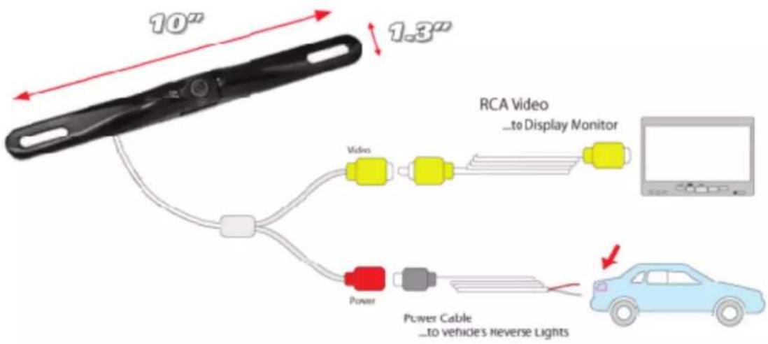
wires to assist in the video camera system setup. See the wiring diagram for connections between cameras, monitor and your vehicle.
PLCMDVR72 INTRODUCTION
This model is with one 7 inch quad monitor with RCA jack, and with 2 mini DVR recorder, and with one super slim license plate backup camera. The 2 mini DVR and backup camera can connect to the 7 inch quad monitor for display. The mini DVR need to insert the TF card( we suggest use class 10 TF card), can be installed one DVR for front view recorder, and the other DVR can be installed for inside of the car recording. The super slim bar style backup camera is for reverse and parking.
Monitor Wiring & Connection

natural_image
Top: a monitor displaying four video feeds of yellow trucks; bottom: connected cables with colored wires (no visible text or symbols)Red and black wire is for 12V power
Green wire is Reverse trigger cable
The 2 yellow RCA jack and red and white RCA jack is the 4 ch video input.
The Reverse trigger cable is for the Ch1, so please connect the reverse backup camera to the Ch1, so when the truck in reverse status, the reverse camera would be priority.
2 pcs Mini DVR connection

natural_image
Close-up of a black electrical plug with wires and connectors, no visible text or symbolsthere is 2 pcs of this mini DVR included in the package for recording( one may installed at the windscreen for front view driving recording, and one can be installed at inside the car for recording ,or other placed customers want to installed)
The DVR cable red and yellow cable is for 12V power, and black for GND, the yellow video jack is video output, connected with the 7 inch monitor for display.
Backup camera connection:
Monitor Buttons:
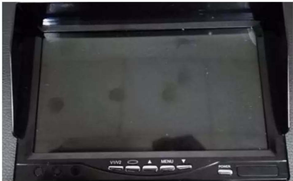
- V1/V2: change the mode, 1 ch, 2ch,3ch,4ch display
- This button for reverse the picture image left and right
- Menu: Adjust the color, brightness, etc.
- Power button
- Increase/Decrease
Remote Control

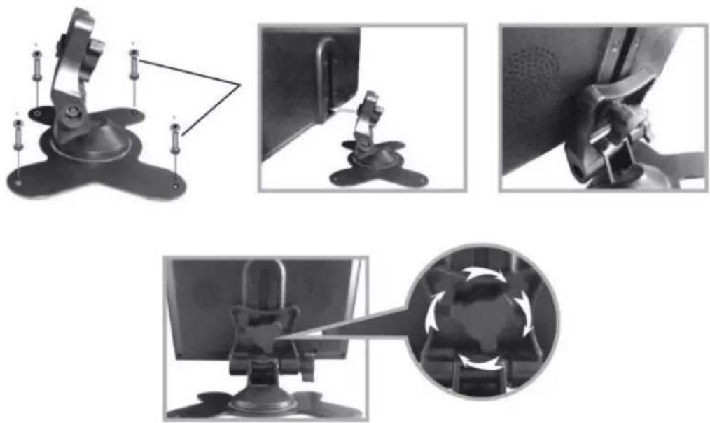
Monitor Stand Mounting
-
Set the mount stand in the desired location, then use screws to secure the mount stand into location. Please make sure asto set a location free from vehicle obstruction include ng any wiring, or location where it may obstruct the driver's view, driving conditions, etc.
-
Attach the metal buckle piece on top of the fan shaped mount stand,
and slide it into the receiving slot in back of the display monitor assembly. This metal buckle should slide in and up to the monitor assembly.
- Set the desired position/height of the buckle into the monitor assembly.
- Tighten the clamp-style knob in the back of the stand mount to secure the monitor in the desired position.
- The angle / tilt position of the stand mount is also adjustable. Located toward the base of the stand mount is another clamp-style knob.


Brand : Pyle
Model : PLCMDVR72
Category : Camera