UBL6H - Unspecified Adj - Free user manual and instructions
Find the device manual for free UBL6H Adj in PDF.

User questions about UBL6H Adj
0 question about this device. Answer the ones you know or ask your own.
Ask a new question about this device
Download the instructions for your Unspecified in PDF format for free! Find your manual UBL6H - Adj and take your electronic device back in hand. On this page are published all the documents necessary for the use of your device. UBL6H by Adj.
USER MANUAL UBL6H Adj
natural_image
Technical line drawing of a mechanical component with circular cutouts and mounting brackets (no text or symbols)User Manual
©2023 ADJ Products, LLC all rights reserved. Information, specifications, diagrams, images, and instructions herein are subject to change without notice. ADJ Products, LLC logo and identifying product names and numbers herein are trademarks of ADJ Products, LLC. Copyright protection claimed includes all forms and matters of copyrightable materials and information now allowed by statutory or judicial law or hereinafter granted. Product names used in this document may be trademarks or registered trademarks of their respective companies and are hereby acknowledged. All non-ADJ Products, LLC brands and product names are trademarks or registered trademarks of their respective companies.
ADJ Products, LLC and all affiliated companies hereby disclaim any and all liabilities for property, equipment, building, and electrical damages, injuries to any persons, and direct or indirect economic loss associated with the use or reliance of any information contained within this document, and/or as a result of the improper, unsafe, insufficient and negligent assembly, installation, rigging, and operation of this product.
Europe Energy Saving Notice
Energy Saving Matters (EuP 2009/125/EC)
Saving electric energy is a key to help protecting the environment. Please turn off all electrical products when they are not in use. To avoid power consumption in idle mode, disconnect all electrical equipment from power when not in use. Thank you!

DOCUMENT VERSION
Due to additional product features and/or enhancements, an updated version of this document may be available online.
Please check www.adj.com for the latest revision/update of this manual before beginning installation and/or programming.
| Date | Document Version | Software Version | DMX Channels Notes | |
| 12/01/2023 | 1.0 1.0 | 6 / 11 / 13 / 16 / 18 / 25 / 28 Ch | Initial release | |
CONTENTS
Introduction 4
Limited Warranty (USA Only) 5
Warranty Registration | Features 6
Safety Precautions 7
Overview 9
Installation 10
Wireless Operation 14
IR Button Colors 16
Remote Device Management (RDM) 17
Control Panel 18
System Menu 19
DMX Set Up 22
DMX Traits 24
Pixel Grouping 27
Color Macros Chart 28
Dim Speeds 29
Dim Modes 30
Primary-Secondary Set Up | Multi Unit Power Linking 31
Maintenance Guidelines 32
Dimensional Drawings 33
Specifications 34
Optional Accessories I FCC Statement 35
INTRODUCTION
Unpacking: Thank you for purchasing the UBL6H by ADJ Products, LLC. Every device has been thoroughly tested and has been shipped in perfect operating condition. Carefully check the shipping carton for damage that may have occurred during shipping. If the carton appears to have been damaged, carefully inspect your fixture for any damage and be sure all accessories necessary to operate the unit have arrived intact. In the event that damage has been found or parts are missing, please contact our toll free customer support number for further instructions. Do not return this unit to your dealer without first contacting customer support.
Introduction: The ADJ UBL6H is an LED bar with 64-built in color macros, DMX capability, wireless remote control, and a variety of useful professional control tools for staging and event application. Its six (6) 20W ultra bright RGBAL+UV (Red, Green, Blue, Amber, Lime, and UV) LEDs allow for a wide array of colors to be produced, tunable color temperature control from 2300K to 9900K. This product is intended to be used by professionally trained personnel only and is not suitable for private use.
Customer Support: Contact ADJ Service for any product related service and support needs. Also visit forums.adj.com with questions, comments or suggestions.
Parts: To purchase parts online visit:
http://parts.adj.com (US)
http://www.adjparts.eu (EU)
ADJ SERVICE USA - Monday - Friday 8:00am to 4:30pm PST
Voice: 800-322-6337 | Fax: 323-582-2941 | support@adj.com
ADJ SERVICE EUROPE - Monday - Friday 08:30 to 17:00 CET
Voice: +31 45 546 85 60 | Fax: +31 45 546 85 96 | support@adj.eu
ADJ PRODUCTS LLC USA
6122 S. Eastern Ave. Los Angeles, CA. 90040
323-582-2650 | Fax 323-532-2941 | www.adj.com | info@adj.com
ADJ SUPPLY Europe B.V
Junostraat 2 6468 EW Kerkrade, The Netherlands
+31 (0)45 546 85 00 | Fax +31 45 546 85 99
www.adj.eu | info@adj.eu
ADJ PRODUCTS GROUP Mexico
AV Santa Ana 30 Parque Industrial Lerma, Lerma, Mexico 52000
+52 (728) 282-7070
Warning! This unit is intended for indoor use only! Do not expose to rain or moisture!
CAUTION! There are no user serviceable parts inside this unit. Do not attempt any repairs yourself, as doing so will void your manufacturer's warranty. In the unlikely event your unit may require service, please contact ADJ Products, LLC.
Do not discard the shipping cartoon in the trash. Please recycle when ever possible.
LIMITED WARRANTY (USA ONLY)
A. ADJ Products, LLC hereby warrants, to the original purchaser, ADJ Products, LLC products to be free of manufacturing defects in material and workmanship for a prescribed period from the date of purchase (see specific warranty period on reverse). This warranty shall be valid only if the product is purchased within the United States of America, including possessions and territories. It is the owner's responsibility to establish the date and place of purchase by acceptable evidence, at the time service is sought.
B. For warranty service, you must obtain a Return Authorization number (RA#) before sending the product back—please contact ADJ Products, LLC Service Department at 800-322-6337. Send the product only to the ADJ Products, LLC factory. All shipping charges must be prepaid. If the requested repairs or service (including parts replacement) are within the terms of this warranty, ADJ Products, LLC will pay return shipping charges only to a designated point within the United States. If the entire instrument is sent, it must be shipped in its original package and packaging material. No accessories should be shipped with the product. If any accessories are shipped with the product, ADJ Products, LLC shall incur no liability whatsoever for loss of or damage to any such accessories, nor for the safe return thereof.
C. This warranty is void if the product serial number and/or labels are altered or removed; if the product is modified in any manner which ADJ Products, LLC concludes, after inspection, affects the reliability of the product; if the product has been repaired or serviced by anyone other than the ADJ Products, LLC factory unless prior written authorization was issued to purchaser by ADJ Products, LLC; if the product is damaged because it was not properly maintained as set forth in the product instructions, guidelines and/or user manual.
D. This is not a service contract, and this warranty does not include maintenance, cleaning, or periodic check-up. During the period specified above, ADJ Products, LLC will replace defective parts at its expense with new or refurbished parts, and will absorb all expenses for warranty service and repair labor by reason of defects in material or workmanship. The sole responsibility of ADJ Products, LLC under this warranty shall be limited to the repair of the product, or replacement thereof, including parts, at the sole discretion of ADJ Products, LLC. All products covered by this warranty were manufactured after August 15, 2012, and bear identifying marks to that effect.
E. ADJ Products, LLC reserves the right to make changes in design and/or improvements upon its products without any obligation to include these changes in any products theretofore manufactured.
F. No warranty, whether expressed or implied, is given or made with respect to any accessory supplied with products described above. Except to the extent prohibited by applicable law, all implied warranties made by ADJ Products, LLC in connection with this product, including warranties of merchantability or fitness, are limited in duration to the warranty period set forth above. And all warranties, whether expressed or implied, including warranties of merchantability or fitness, are limited in duration to the warranty period set forth above. The consumer's and/or dealer's sole remedy shall be such repair or replacement as is expressly provided above; and under no circumstances shall ADJ Product, LLC be liable for any loss and/or damage, direct and/or consequential arising out of the use of, and/or inability to use this product.
G. This warranty is the only written warranty applicable to ADJ Products, LLC products, and supersedes all prior warranties and written descriptions of warranty terms and conditions heretofore published.
MANUFACTURER'S LIMITED WARRANTY PERIODS:
- Non-LED Lighting Products = 1-Year (365 Days) (Including Special Effect Lighting, Intelligent Lighting, UV lighting, Strobes, Fog Machines, Bubble Machines, Mirror Balls, Par Cans, Trussing, Lighting Stands, Power/Data Distribution, etc. excluding LED and lamps)
- Laser Products = 1-Year (365 Days) (excluding laser diodes which have a 6-Month Limited Warranty)
- LED Products = 2-Year (730 Days) (excluding batteries which have a 180 Day Limited Warranty)
- NOTE: 2-Year (730 Days) Limited Warranty ONLY applies to product purchased within the United States. StarTec Series = 1-Year (365 Days) (excluding batteries which have a 180 Day Limited Warranty)
• ADJ DMX Controllers = 2 Year (730 Days)
• American Audio Products = 1 Year (365 Days)
WARRANTY REGISTRATION
Please fill out the enclosed warranty card to validate your purchase. All returned service items, whether under warranty or not, must be freight pre-paid and accompanied by a return authorization (R.A.) number. The R.A. number must be clearly written on the outside of the return package. A brief description of the problem as well as the R.A. number must also be written down on a piece of paper included in the shipping carton. If the unit is under warranty, you must provide a copy of your proof of purchase invoice. You may obtain an R.A. number by contacting our customer support team. All packages returned to the service department not displaying an R.A. number on the outside of the package will be returned to the shipper.
FEATURES
• Linear Color Temperature Control (2,300K to 9,900K)
- Smooth RGBAL+UV color mixing
• Horizontal Magnetic Alignment feature (Built-In)
- Compatible with the ADJ UC-IR24 remote. Operates at a distance of up to 32.8 feet (10 meters)
INCLUDED ITEMS
- Power Cable (x1)
• UC-IR24 Remote Control (x1) - 20^ Diffusion Filter (x1)
- Mounting Brackets for Ground or Truss Mounting (x2)
SAFETY PRECAUTIONS
CAUTION
HIGH INTENSITY ULTRAVIOLET LIGHT

natural_image
Symmetrical starburst graphic with central circle labeled 'UV' (no additional text or symbols)AVOID DIRECT EYE & SKIN EXPOSURE. WEAR PROPER EYE & SKIN PROTECTION. SEE MANUAL FOR SAFETY INSTRUCTIONS.
RISK GROUP 3 - RISK OF EXPOSURE TO ULTRAVIOLET UV RADIATION!
FIXTURE EMITS HIGH INTENSITY WAVELENGTH OF ULTRAVIOLET UV LIGHT FROM THE UV COLOR FILTER.
WEAR PROPER EYE AND SKIN PROTECTION. AVOID PROLONGED PERIODS OF EXPOSURE TO UV COLOR FILTER.
AVOID WEARING WHITE COLOR CLOTHING AND/OR USING UV PAINTS ON SKIN. AVOID DIRECT EYE AND/OR SKIN EXPOSURE AT DISTANCES LESS THAN 11 feet (3.3m).
DO NOT OPERATE FIXTURE WITH DAMAGED/MISSING EXTERNAL COVERS.
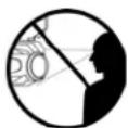
DO NOT LOOK DIRECTLY INTO THE UV LIGHT AND/OR VIEW UV LIGHT DIRECTLY WITH OPTICAL INSTRUMENTS THAT MAY CONCENTRATE THE LIGHT/RADIATION OUTPUT.
INDIVIDUALS SUFFERING FROM A RANGE OF EYE CONDITIONS, SUNLIGHT EXPOSURE DISORDERS, OR INDIVIDUALS USING PHOTOSENSITIVE MEDICATION, MAY EXPERIENCE DISCOMFORT IF EXPOSED TO THE ULTRAVIOLET UV LIGHT EMITTED FROM THE UV LED.
SAFETY PRECAUTIONS
PROTECTION CLASS 1 - FIXTURE MUST BE PROPERLY GROUNDED.

THERE ARE NO USER SERVICEABLE PARTS INSIDE THIS UNIT. DO NOT ATTEMPT ANY REPAIRS YOURSELF, AS DOING SO WILL VOID YOUR MANUFACTURER'S WARRANTY. DAMAGES RESULTING FROM MODIFICATIONS TO THIS FIXTURE AND/OR THE DISREGARD OF SAFETY INSTRUCTIONS AND GUIDELINES IN THIS MANUAL VOID THE MANUFACTURER'S WARRANTY AND ARE NOT SUBJECT TO ANY WARRANTY CLAIMS AND/OR REPAIRS.
NEVER LOOK DIRECTLY INTO THE LIGHT SOURCE! RETINA INJURY RISK - MAY INDUCE BLINDNESS! SENSITIVE PERSONS MAY SUFFER AN EPILEPTIC SHOCK!
- Ambient operating temperature is -4^ to 113^ (-20°C to 45°C)!
- DO NOT TOUCH the fixture housing during operation. Disconnect the power and allow approximately 15 minutes for the fixture to cool down before servicing.
• DO NOT shake the fixture, and avoid brute force when installing and/or operating the fixture. - DO NOT operate the fixture if the power cord has become frayed, crimped and/or damaged. If the power cord is damaged, replace immediately with a new one of the same power rating.
- DO NOT attempt to remove or break off the ground prong from the electrical cord. This prong is used to reduce the risk of electrical shock and fire in case of an internal short.
- DO NOT attempt to operate this unit if it has been damaged in any way.
- Disconnect from main power before making any type of connection.
- DO NOT block any air ventilation slots. All fan and air inlets must remain clean and never blocked. Allow approx. 6" (15cm) between fixture and other devices or a wall for proper cooling.
- Always be sure to mount this unit in an area that will allow proper ventilation. Allow about 6" (15cm) between this device and a wall.
- This device is intended for indoor use only! Outdoors usage voids all manufacturer's warranties.
- DO NOT remove the cover for any reason.
- When installing fixture in a suspended environment, always use mounting hardware that is no less than M10 x 25mm, and always install fixture with an appropriately rated safety cable.
- Never plug this unit in to a dimmer pack.
- During long periods of non-use, disconnect the unit's main power.
• Always mount this unit in safe and stable matter. - Power-supply cords should be routed so that they are not likely to be walked on or pinched by items placed upon or against them, paying particular attention to the point where they exit from the unit.
- Cleaning - The fixture should be cleaned only as recommended by the manufacturer.
- Heat - The appliance should be situated away from heat sources such as radiators, heat registers, stoves, or other appliances (including amplifiers) that produce heat.
- The fixture should be serviced by qualified service personnel when:
A. The power-supply cord or the plug have been damaged.
B. Objects have fallen onto, or liquids have been spilled into, the fixture.
C. The fixture does not appear to operate normally or exhibits a marked change in performance.
D. The fixture has fallen and/or has been subjected to extreme handling.
OVERVIEW
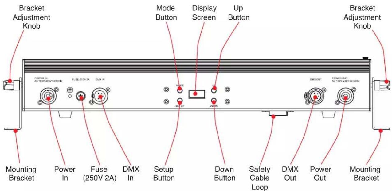
text_image
Bracket Adjustment Knob Power IN: AC 100V 240V 50/60Hz FUSE: 250V 2A DMX IN Mode Button Display Screen Up Button Bracket Adjustment Knob Mounting Bracket Power In Fuse (250V 2A) DMX In Setup Button Down Button Safety Cable Loop DMX Out Power Out Mounting BracketINSTALLATION

DO NOT INSTALL THE FIXTURE IF YOU ARE NOT QUALIFIED TO DO SO!
Fixture MUST be installed following all local, national, and country commercial electrical and construction codes and regulations.
When installing the unit, the trussing or area of installation must be able to hold 10 times the weight of the unit and any attached accessories without any deformation. The unit must be secured with a secondary safety attachment, e.g. an appropriately-rated safety cable.
Before rigging/mounting a single fixture to any metal truss/structure or placing the fixture(s) on any surface, a professional equipment installer MUST be consulted to determine if the metal truss/structure or surface is properly certified to safely hold the combined weight of the fixture(s), clamps, cables, and accessories.
Ambient operating temperature is range -4^ to 113^ ( -20^ to 45^ ). Do not operate this device when ambient temperature falls outside of this range.
Fixture(s) should be installed away from walking paths, seating areas, or areas where unauthorized personnel might reach the fixture by hand.
NEVER stand directly below the fixture(s) when rigging, removing, or servicing.
Overhead fixture installation must always be secured with a secondary safety attachment, such as an appropriately rated safety cable that can hold 10 times the weight of the fixture.
Overhead mounting requires extensive experience, including calculating working load limits, knowledge of installation material being used, and periodic safety inspection of all installation material as well as the unit itself. If you lack these qualifications, do not attempt the installation yourself.
The installaiton should be checked by a skilled person once a year.
INSTALLATION
CLAMP MOUNTING
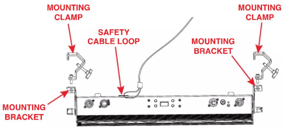
This fixture features two mounting brackets for the attachment of mounting clamps. When mounting the fixture to a truss or any other suspended structure, be sure to secure an appropriate rated clamp (not included) to each mounting bracket. Insert a bolt of appropriate size through the bottom of the mounting clamp and the central hole on the mounting bracket, and secure them together with a matching nut. Additionally, the unit also features a safety cable loop on the top of the fixture (see the illustration below). Attach a separate SAFETY CABLE of the appropriate weight rating to the provided safety cable loop, then secure the other end to a suitable anchor point. Please note that two mounting clamps must be used to safely and securely install this fixture in a suspended environment.
text_image
MOUNTING CLAMP SAFETY CABLE LOOP MOUNTING BRACKET MOUNTING CLAMP MOUNTING BRACKETSAFETY CABLE:

ALWAYS ATTACH A SAFETY CABLE WHENEVER INSTALLING THIS FIXTURE IN A SUSPENDED ENVIRONMENT TO ENSURE THAT THE FIXTURE WILL NOT FALL IF THE CLAMP FAILS.
INSTALLATION

natural_image
Technical line drawing of a mechanical or electrical enclosure with structural supports and control panels (no text or symbols)The unit is fully operational in three different mounting positions: hanging upside-down from the ceiling or trussing, sideways on trussing, or set on a flat level surface. Be sure this fixture is kept at least 12m (40ft) away from any flammable materials (decorations, etc). Always use and install a safety cable (not included) as a safety measure to prevent accidental damage and/or injury in the event the clamp fails. Never use the carrying handles for secondary attachment.
ACCESSORY INSTALLATION
DIFFUSION FILTER
A removeable 20-degree diffusion filter is included with the fixture. To install this filter, simply remove the retaining screw on the side of the fixture's lens and slide the diffusion filter into the slot located in front of the lens. Align the hole in the diffusion filter with the retaining screw hole, then re-install and tighten the retaining screw to secure the filter in place. Please note that the diffusion filter has holes at both ends to allow the filter to be installed facing either direction.
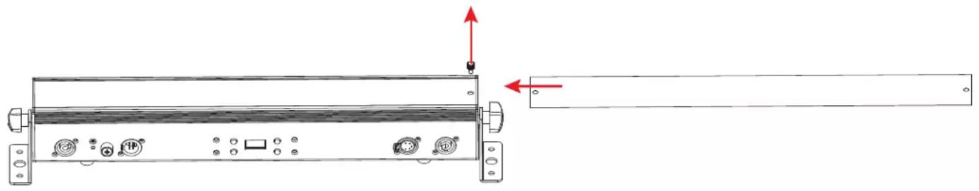
natural_image
Technical line drawing of a device chassis with ports and connectors, showing no text or symbolsIn addition, a 1x40-degree diffusion filter is offered as an optional accessory that is sold separately. Please refer to the Ordering Information section of this manual.
WIRELESS OPERATION
To set up wireless control, follow the steps below:
- Navigate to Personality > IR Remote in the system menu. Press SETUP to select this menu.
- Use UP and DOWN to scroll to the "On" option, then press SETUP to confirm.
There are many factors that can affect and/or interrupt a wireless signal, including walls, glass, metal, objects, and people. Therefore, the following guidelines are recommended in order to maximize the chances of having a clear path for the wireless signal to reach the device:
• Install the device a minimum of 9.8 ft (3m) above audiences and/or ground level.
- Arrange the wireless antenna in an upright, vertical position.
- Position devices in direct line of sight of the transmitting controller.
Careful planning and testing of the selected installation location is critical to ensure optimum and reliable wireless operation.

text_image
9.8 ft (3m) Above GroundWIRELESS OPERATION
The unit can only be controlled when it has been set to Primary mode. The unit will NOT respond to commands when it has been set to Secondary mode.
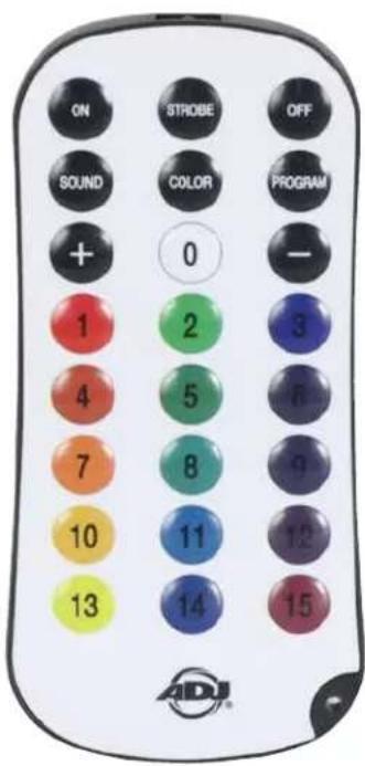
UC IR24 CONTROLS
- On: Fixture turns on and reverts to the last running state
- Off: Fixture goes into stand by mode in a blackout state.
- Strobe: Actives strobe mode, using the currently selected color or program. The strobe rate can be adjusted using the + / - buttons, or one of the 15 pre-set strobe speeds can be selected using the number keys. 1 is the slowest strobe speed, and 15 is the fastest.
- Sound: Activates sound mode, with displays triggered by microphone inputs. Microphone sensitivity can be adjust using the + / - buttons.
- Color: Activates color mode. Select a static color (0-15) using the number keys. The intensity for the set color can then be adjusted with the +/- buttons. Refer to the Color Mode Programs section of this manual for detailed information.
- Program: Activates interla program mode. Select an internal program (0-15) using the number keys. The selected program run speed can be adjusted with the + / - buttons. Note: 13 of the 15 buttons will activate a program for this unit.
-
- and - buttons: Adjusts strobe rate, mic sensitivity, intensity, brightness intensity, or program run speed. The + / - buttons can be repeatedly pressed to increase or decrease by individual level increments, or pressed and held to quickly make large adjustments at once.
• Number Keys (0-15): These buttons are used to select preset strobe speeds, static colors, and internal programs. Colors stored in the number keys can be edited from the units menu if desired.
- and - buttons: Adjusts strobe rate, mic sensitivity, intensity, brightness intensity, or program run speed. The + / - buttons can be repeatedly pressed to increase or decrease by individual level increments, or pressed and held to quickly make large adjustments at once.
text_image
ON STROBE OFF SOUND COLOR PROGRAM + 0 - 1 2 3 4 5 6 7 8 9 10 11 12 13 14 15 ADJ®IR BUTTON COLORS
IR DEFAULT VALUES
| BUTTON RED GREEN BLUE LIME AMBER UV | ||||||
| 0 0 0 0 | 255 0 0 | |||||
| 1 255 0 | 0 0 0 0 | |||||
| 2 0 255 | 0 0 0 0 | |||||
| 3 0 0 25 | 5 0 0 0 | |||||
| 4 231 68 | 0 0 0 0 | |||||
| 5 0 117 | 58 0 0 0 | |||||
| 6 | 17 0 75 | 0 0 44 | ||||
| 7 255 83 | 0 0 63 0 | |||||
| 8 0 109 | 70 0 0 0 | |||||
| 9 | 32 0 75 | 0 22 35 | ||||
| 10 | 0 0 0 0 | 255 0 | ||||
| 11 | 0 | 114 | 160 | 0 | 0 | 0 |
| 12 82 0 | 35 0 0 74 | |||||
| 13 | 255 | 255 0 0 | 255 0 | |||
| 14 | 0 75 | 36 0 0 0 | ||||
| 15 81 0 | 35 0 0 115 | |||||
EDITING IR BUTTON VALUES
These fixtures allow the user to create custom RGBAL values and assign them to the numbered keys (0-15) on the remote control. Follow the steps below:
- In the main system menu, press MODE to navigate to "Personality," then press SETUP. Use the UP and DOWN buttons to scroll to "IR Button Colors," then press SETUP again.
- Use the UP and DOWN buttons to scroll to the number of the remote button that you would like to use. Options range from "Button 0" to "Button 15." Press SETUP to select the button shown on the display screen.
- Create a custom color for the button you have selected by using the UP and DOWN buttons to scroll through the color component options (Red, Green, Blue, Lime, Amber, UV). Press SETUP to select a color component option, then use the UP and DOWN buttons to adjust the intensity of that color component option. Selectable values range from 000 to 255. Repeat this process until you have set the desired Red, Green, Blue, Lime, Amber, and UV intensities to create your custom color.
NOTE: Once you have created and assigned a custom color value to a remote button, the default color for the remote button will be overridden. This means that the output color of the fixture may no longer resemble the color shown on the remote button. To return to the default color values, reset the unit to the default factory settings by navigating to Personality > Service > Factory Restore.
NOTE: If multiple units have been linked in a primary-secondary set up, the custom color values only need to be set up on the primary unit. The custom color settings will carry over automatically to any secondary units in the system.
REMOTE DEVICE MANAGEMENT (RDM)
NOTE: In order for RDM to work properly, RDM enabled equipment must be used throughout the entire system, including DMX data splitters and wireless systems.
Remote Device Management (RDM) is a protocol that sits on top of the DMX512 data standard for lighting, allowing the DMX systems of the fixtures to be modified and monitored remotely. This protocol is ideal for instances in which a unit is installed in a location that is not easily accessible.
With RDM, the DMX512 system becomes bi-directional, allowing a compatible RDM enabled controller to send out a signal to devices on the wire, as well as allowing the fixture to respond (known as a GET command). The controller can then use its SET command to modify settings that would typically have to be changed or viewed directly via the unit's display screen, including the DMX Address, DMX Channel Mode, and Temperature Sensors.
FIXTURE RDM INFORMATION:
| RDM Code Device ID Device Model ID Personality ID | |||
| 1900 0000 | -FFFF 7906 | 6Ch (1); 11Ch (2); 13Ch (3); 16Ch (4); 18Ch (5); 25Ch (6); 28Ch (7) | |
Please be aware that not all RDM devices support all RDM features, and therefore it is important to check beforehand to ensure that the equipment that you are considering includes all of the features that you require.
| Disc Unique Branch [0x0001] |
| Disc Mute [0x0002] |
| Disc Un Mute [0x0003] |
| Supported Parameters [0x0050] |
| Device Info [0x0060] |
| Manufacturer Label [0x0081] |
| Device Label [0x0082] |
| Software Version Label [0x00C0] |
| DMX Personality [0x00E0] |
| DMX Start Address [0x00F0] |
| Sensor Value [0x0201c] |
| Curve [0x0343] |
| Curve Description [0x0344] |
| Identify Device [0x1000] |
| DMX Fail Mode [0x0141] |
CONTROL PANEL
This unit features a display screen with a 4-button control pad, which can be used to easily adjust any device settings.
Pressing the MODE button will cycle through the various Main Menu options. When the desired Main Menu option is displayed on the screen, press the SETUP button to enter the sub-menu, then use the UP and DOWN buttons to scroll through sub-menu options. In some cases, there will be a second sub-menu that can be navigated in the same way.
MODE


SET UP
natural_image
Empty rectangular frame with no text, numbers, or symbols insideUP


DOWN
SCREEN LOCK
The control panel screen will lock after a period of inactivity which can be set by navigating to Personality > Display > Lock. Default time is 30 seconds. To unlock the screen, press and hold the MODE button for 10 seconds.
SYSTEM MENU
| DMX SET | Address 001 - 512 | Set DMX starting address | ||
| Ch. Mode | 6Ch | Select DMX channel mode | ||
| 11Ch | ||||
| 13Ch | ||||
| 16Ch | ||||
| 18Ch | ||||
| 25Ch | ||||
| 28Ch | ||||
| No DMX | Hold | Unit holds last settings if DMX signal is lost or interrupted | ||
| Blackout | Unit defaults to blackout mode if DMX signal is lost or interrupted | |||
| Manual | Unit defaults to manual settings if DMX signal is lost or interrupted | |||
| Internal Programs | Unit defaults to selected internal program if DMX signal is lost or interrupted | |||
| PERSONALITY | Primary/Secondary Mode | Primary / Secondary | Set unit as a primary or a secondary | |
| IR Remote On / Off | Activate or deactivate remote control function | |||
| RDM On / Off | Activate or deactivate RDM | |||
| Pixel Flip | Off = 1-3 | Set pixel assignment configuration; refer to Pixel Grouping section | ||
| On = 3-1 | ||||
| Dim Mode | Standard | Select dim mode | ||
| Stage | ||||
| TV | ||||
| Archi | ||||
| Theatre | ||||
| Stage 2 | ||||
| Dim Speed 0.1s - 10s | ||||
| CONTINUED ON NEXT PAGE | ||||
SYSTEM MENU
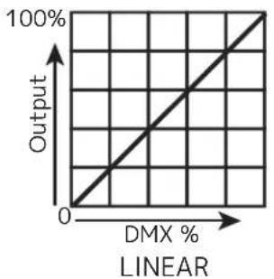
| PERSONALITY (continued) | Dim Curve | Linear | Select dim curve | ||
| Square | |||||
| Inv. Squa. | |||||
| S. Curve | |||||
| Display | Save Dlay 1 - 10 | Display goes into screen saver mode after set period of inactivity | |||
| Lock Off, 1min - 10 | 0min | Dispaly controls lock after set period of inactivity; to unlock press and hold MODE for 10 sec | |||
| Rotate Display 180° | Yes | Inverted display orientation | |||
| No | Standard display orientation | ||||
| Auto | Automatically keep display upright | ||||
| IR Button Colors | Button 0 | Red 000 - 255 | Configure color mix for each remote button | ||
| Green 000 - 255 | |||||
| Blue 000 - 255 | |||||
| Amber 000 - 255 | |||||
| Lime 000 - 255 | |||||
| UV 000 - 255 | |||||
| Button 1 | Red 000 - 255 | ||||
| Green 000 - 255 | |||||
| Blue 000 - 255 | |||||
| Amber 000 - 255 | |||||
| Lime 000 - 255 | |||||
| UV 000 - 255 | |||||
| ... ... ... | |||||
| Button 15 | Red 000 - 255 | ||||
| Green 000 - 255 | |||||
| Blue 000 - 255 | |||||
| Amber 000 - 255 | |||||
| Lime 000 - 255 | |||||
| UV 000 -255 | |||||
| Service Passcode = 011 Restore Yes / No | Return unit to default factory settings | ||||
| CONTINUED ON NEXT PAGE | |||||
SYSTEM MENU
| MANUAL | Red 000 - 255 | Manually set each system parameter; please note that these settings take precedent when no DMX signal is present | |||
| Green 000 - 255 | |||||
| Blue 000 - 255 | |||||
| Amber 000 - 255 | |||||
| Lime 000 - 255 | |||||
| UV 000 - 255 | |||||
| Clr Macro 000 - 063 | |||||
| Clr Temp No Function, 2300K - 9900K | |||||
| Clr Temp Pr | No Function, 2300K, 2600K, 2900K, 3200K, 3600K, 3900K, 4200K, 4500K, 4900K, 5500K, 6000K, 7000K, 8000K, 9000K, 9900K | ||||
| Strobe 000 - 255 | |||||
| Mastr Dim 000 - 255 | |||||
| INT PROGS | Program 0 | Speed 000 - 255 | Adjust parameters for each internal program | ||
| Fade 000 - 255 | |||||
| Sound On / Off 001 - 016 | |||||
| Program 1 | Speed 000 - 255 | ||||
| Fade 000 - 255 | |||||
| Sound On / Off 001 - 016 | |||||
| ... ... ... ... | |||||
| Program 13 | Speed 000 - 255 | ||||
| Fade 000 - 255 | |||||
| Sound On / Off 001 - 016 | |||||
| INFO | LED Temperature | xxx F / C | Current LED temperature | ||
| RDM UID xxxxxx | Displays RDM UID | ||||
| Software Version | x.xx | Displays software version | |||
DMX SET UP
DMX-512: DMX is short for Digital Multiplex. This is a universal protocol used as a form of communication between intelligent fixtures and controllers. A DMX controller sends DMX data instructions from the controller to the fixture. DMX data is sent as serial data that travels from fixture to fixture via the DATA "IN" and DATA "OUT" XLR terminals located on all DMX fixtures (most controllers only have a DATA "OUT" terminal).
DMX Linking: DMX is a language allowing all makes and models of different manufacturers to be linked together and operate from a single controller, as long as all fixtures and the controller are DMX compliant. To ensure proper DMX data transmission, try to use the shortest cable path possible when linking several DMX fixtures. The order in which fixtures are connected in a DMX line does not influence the DMX addressing. For example, a fixture assigned a DMX address of 1 may be placed anywhere in a DMX line: at the beginning, at the end, or anywhere in the middle. When a fixture is assigned a DMX address of 1, the DMX controller knows to send DATA assigned to address 1 to that unit, no matter where it is located in the DMX chain.
Data Cable (DMX Cable) Requirements (For DMX Operation): This unit can be controlled via DMX-512 protocol. The DMX address is set on the rear panel of the unit. Your unit and your DMX controller require a standard 5-pin XLR connector for data input and data output. We recommend Accu-Cable DMX cables. If you are making your own cables, be sure to use standard 110-120 Ohm shielded cable (This cable may be purchased at almost all pro lighting stores). Your cables should be made with a male XLR connector at one end and a female XLR connector at the other. Also remember that DMX cable must be daisy chained and cannot be split.
Notice: Be sure to follow fthe illustration below when making your own cables. Do not use the ground lug on the XLR connector. Do not connect the cable's shield conductor to the ground lug or allow the shield conductor to come in contact with the XLR's outer casing. Grounding the shield could cause a short circuit and erratic behavior.

text_image
COMMON DMX + DMX - NOT USED NOT USEDDMX SET UP
Special Note: Line Termination. When longer runs of cable are used, you may need to use a terminator on the last unit to avoid erratic behavior. A terminator is a 110-120 ohm 1/4 watt resistor which is connected between pins 2 and 3 of a male XLR connector (DATA + and DATA -). This unit is inserted in the female XLR connector of the last unit in your daisy chain to terminate the line. Using a cable terminator (ADJ part number Z-DMX/T) will reduce the risk of erratic behavior.


A DMX512 terminator reduces signal errors, avoiding most signal reflection interference. Connect PIN 2 (DMX-) and PIN 3 (DMX+) of the last fixture in series with a 120 Ohm, 1/4 W Resistor to terminate the DMX512.
DMX ADDRESSING.
All fixtures should be given a DMX starting address when using a DMX controller, so the correct fixture responds to the correct control signal. This digital starting address is the channel number from which the fixture starts to “listen” to the digital control signal sent out from the DMX controller. The assignment of this starting DMX address is achieved by setting the correct DMX address on the digital control display on the fixture.
You can set the same starting address for all fixtures or a group of fixtures, or set different addresses for each individual fixture. Setting all fixtures to the same DMX address will cause all fixtures to react in the same way. In other words, changing the settings of one channel will affect all the fixtures simultaneously.
If you set each fixture to a different DMX address, each unit will start to "listen" to the channel number you have set, based on the quantity of DMX channels of each fixture. That means changing the settings of one channel will only affect the selected fixture.
For example, when this unit is operating in 6 channel mode, you should set the starting DMX address of the first unit to 1, the second unit to 7 (1 + 6), the third unit to 13 (1 + 6 + 6), and so on. See the chart below for more details.
| CHANNEL MODE | UNIT 1 ADDRESS | UNIT 2 ADDRESS | UNIT 3 ADDRESS | UNIT 4 ADDRESS |
| 6Ch 1 7 13 | 19 | |||
| 11Ch 1 12 23 | 34 | |||
| 13Ch 1 14 27 | 40 | |||
| 16Ch 1 17 33 | 49 | |||
| 18Ch 1 19 37 | 55 | |||
| 25CH 1 26 51 | 76 | |||
| 28Ch 1 29 57 | 85 |
DMX TRAITS
| CHANNEL | DMX VALUES | FUNCTION | ||||||
| 6Ch 1 | 1Ch 13 | Ch 16Ch | Ch 18Ch | 25Ch 28Ch | ||||
| 1 1 | 1 000 | - 255 All Red, 0% to 100% | ||||||
| 2 2 | 2 000 | - 255 All Green, 0% to 100% | ||||||
| 3 3 | 3 000 | - 255 All Blue, 0% to 100% | ||||||
| 4 4 | 4 000 | - 255 All Amber, 0% to 100% | ||||||
| 5 5 | 5 000 | - 255 All Lime, 0% to 100% | ||||||
| 6 6 | 6 000 | - 255 All UV, 0% to 100% | ||||||
| 1 1 1 | 000 - 255 Red 1, 0% to 100% | |||||||
| 2 2 2 | 000 - 255 Green 1, 0% to 100% | |||||||
| 3 3 3 | 000 - 255 Blue 1, 0% to 100% | |||||||
| 4 4 4 | 000 - 255 Amber 1, 0% to 100% | |||||||
| 5 5 5 | 000 - 255 Lime 1, 0% to 100% | |||||||
| 6 6 6 | 000 - 255 UV 1, 0% to 100% | |||||||
| 7 7 7 | 000 - 255 Red 2, 0% to 100% | |||||||
| 8 8 8 | 000 - 255 Green 2, 0% to 100% | |||||||
| 9 9 9 | 000 - 255 Blue 2, 0% to 100% | |||||||
| 10 10 | 10 000 - 255 Amber 2, 0% to 100% | |||||||
| 11 11 | 11 000 - 255 Lime 2, 0% to 100% | |||||||
| 12 12 | 12 000 - 255 UV 2, 0% to 100% | |||||||
| 13 13 | 13 000 - 255 Red 3, 0% to 100% | |||||||
| 14 14 | 14 | 000 - 255 Green 3, 0% to 100% | ||||||
| 15 15 | 15 000 - 255 Blue 3, 0% to 100% | |||||||
| 16 16 | 16 000 - 255 Amber 3, 0% to 100% | |||||||
| 17 17 | 17 000 - 255 Lime 3, 0% to 100% | |||||||
| 18 18 | 18 000 - 255 UV 3, 0% to 100% | |||||||
| 7 7 7 | 19 19 000 - 255 | Color Macros, see Color Macros Chart section of this manual | ||||||
| 8 8 8 | 20 20 000 - 255 | Color Temperature, 2300K - 9900K Linear | ||||||
| 9 9 9 | 21 21 | Color Temperature Presets | ||||||
| 000 - 010 No Function | ||||||||
| 011 - 026 2300K | ||||||||
| 027 - 043 | 2700K | |||||||
| 044 - 060 3000K | ||||||||
| 061 - 076 3200K | ||||||||
| 077 - 093 4000K | ||||||||
| 094 - 110 4500K | ||||||||
| 111 - 126 | 5000K | |||||||
| 127 - 143 5600K | ||||||||
| 144 - 160 6500K | ||||||||
| CONTINUED ON NEXT PAGE | ||||||||
DMX TRAITS
| CHANNEL | DMX VALUES | FUNCTION | ||||||
| 6Ch 1 | 1Ch 13 | Ch 16Ch | Ch 18Ch | 25Ch 28Ch | ||||
| 9 9 9 | 21 21 | Color Temperature Presets (continued) | ||||||
| 161 - 176 7 | 000K | |||||||
| 177 - 193 7 | 500K | |||||||
| 194 - 210 8 | 000K | |||||||
| 211 - 226 8 | 500K | |||||||
| 227 - 255 9 | 900K | |||||||
| 10 10 | 10 22 | 22 | Shutter / Strobe | |||||
| 000 - 031 L | EDs Off | |||||||
| 032 - 063 L | EDs On | |||||||
| 064 - 095 Strobe Effect, slow to fast | ||||||||
| 096 - 127 L | EDs On | |||||||
| 128 - 159 Pulse Effect in Sequences | ||||||||
| 160 - 191 L | EDs On | |||||||
| 192 - 223 Random Strobe Effect, slow to fast | ||||||||
| 224 - 255 L | EDs On | |||||||
| 11 | 11 | 11 | 23 | 23 | 000 - 255 | Dimmer Intensity, 0% to 100% | ||
| 12 | 24 | Auto Programs | ||||||
| 000 - 010 Off | ||||||||
| 011 - 026 Program 1 | ||||||||
| 027 - 043 Program 2 | ||||||||
| 044 - 060 Program 3 | ||||||||
| 061 - 076 Program 4 | ||||||||
| 077 - 093 Program 5 | ||||||||
| 094 - 110 Program 6 | ||||||||
| 111 - 126 | Program 7 | |||||||
| 127 - 143 Program 8 | ||||||||
| 144 - 160 Program 9 | ||||||||
| 161 - 176 Program 10 | ||||||||
| 177 - 193 Program 11 | ||||||||
| 194 - 210 Program 12 | ||||||||
| 211 - 226 Program 13 | ||||||||
| 227 - 255 No Function | ||||||||
| 13 | 25 00 | 0 - 255 Auto Program Speed, slow to fast | ||||||
| 14 | 26 00 | 0 - 255 Auto Program Fade, 0% to 100% | ||||||
| CONTINUED ON NEXT PAGE | ||||||||
DMX TRAITS
| CHANNEL | DMX VALUES | FUNCTION | ||||||
| 6Ch 11Ch 13 | Ch 16Ch 18Ch | 25Ch 28Ch | Dim Mode | |||||
| 12 15 24 27 | 000 - 020 Ddefault to Unit Setting | |||||||
| 021 - 040 Standard | ||||||||
| 041 - 060 Stage | ||||||||
| 061 - 080 TV | ||||||||
| 081 - 100 Architectural | ||||||||
| 101 - 120 Theatre | ||||||||
| 121 - 140 Stage 2 | ||||||||
| 140 - 160 Dim Speed, fast to slow (0.1s to 10s) | ||||||||
| 161 - 255 Default to Unit Setting | ||||||||
| 13 16 25 28 | Dim Curves | |||||||
| 000 - 020 Square | ||||||||
| 021 - 040 Linear | ||||||||
| 041 - 060 Inv. Squa | ||||||||
| 061 - 080 S. Curve | ||||||||
| 081 - 255 No Function | ||||||||
PIXEL GROUPING
PIXEL FLIP OFF
1 2 3

natural_image
Technical line drawing of a mechanical component with four circular features and mounting brackets (no text or symbols)PIXEL FLIP ON
321

natural_image
Technical line drawing of a mechanical component with four circular features and mounting brackets (no text or symbols)COLOR MACROS CHART
| DMX VALUES | COLORS |
| 000 - 003 Off | |
| 004 - 007 Red | |
| 008 - 011 Green | |
| 012 - 015 Blue | |
| 016 - 019 Lime | |
| 020 - 023 Amber | |
| 024 - 027 UV | |
| 028 - 031 R+G | |
| 032 - 035 R+B | |
| 036 - 039 R+L | |
| 040 - 043 R+A | |
| 044 - 047 R+UV | |
| 048 - 051 G+B | |
| 052 - 055 G+L | |
| 056 - 059 G+A | |
| 060 - 063 G+UV | |
| 064 - 067 B+L | |
| 068 - 071 B+A | |
| 072 - 075 B+UV | |
| 076 - 079 L+A | |
| 080 - 083 L+UV | |
| 084 - 087 A+UV | |
| 088 - 091 R+G+B | |
| 092 - 095 | R+G+L |
| 096 - 099 | R+G+A |
| 100 - 103 | R+G+UV |
| 104 - 107 | R+B+L |
| 108 - 111 | R+B+A |
| 112 - 115 | R+B+UV |
| 116 - 119 R+L+A | |
| 120 - 123 | R+L+UV |
| 124 - 127 | R+A+UV |
| DMX VALUES COLORS | |
| 128 - 131 | G+B+L |
| 132 - 135 | G+B+A |
| 136 - 139 | G+B+UV |
| 140 - 143 | G+L+A |
| 144 - 147 | G+L+UV |
| 148 - 151 | G+A+UV |
| 152 - 155 | B+L+A |
| 156 - 159 | B+L+UV |
| 160 - 163 | B+A+UV |
| 164 - 167 | L+A+UV |
| 168 - 171 | R+G+B+L |
| 172 - 175 | R+G+B+A |
| 176 - 179 | R+G+B+UV |
| 180 - 183 | R+G+L+A |
| 184 - 187 | R+G+L+UV |
| 188 - 191 | R+G+A+UV |
| 192 - 195 | R+B+L+A |
| 196 - 199 | R+B+L+UV |
| 200 - 203 | R+B+A+UV |
| 204 - 207 | R+L+A+UV |
| 208 - 211 | G+B+L+A |
| 212 - 215 | G+B+L+UV |
| 216 - 219 | G+B+A+UV |
| 220 - 223 | G+L+A+UV |
| 224 - 227 | B+L+A+UV |
| 228 - 231 | R+G+B+L+A |
| 232 - 235 | R+G+B+L+UV |
| 236 - 239 R+ | G+B+A+UV |
| 240 - 243 | R+G+L+A+UV |
| 244 - 247 | R+B+L+A+UV |
| 248 - 251 | G+B+L+A+UV |
| 252 - 255 | R+G+B+L+A+UV |
DIM SPEEDS
| DMX VALUES DELAY TIME | |
| 141 0.1 sec | |
| 142 0.2 sec | |
| 143 0.3 sec | |
| 144 0.4 sec | |
| 145 0.5 sec | |
| 146 0.6 sec | |
| 147 0.7 sec | |
| 148 0.8 sec | |
| 149 0.9 sec | |
| 150 1.0 sec | |
| 151 1.5 sec | |
| 152 2.0 sec | |
| 153 3.0 sec | |
| 154 4.0 sec | |
| 155 5.0 sec | |
| 156 6.0 sec | |
| 157 7.0 sec | |
| 158 8.0 sec | |
| 159 9.0 sec | |
| 160 10.0 sec | |
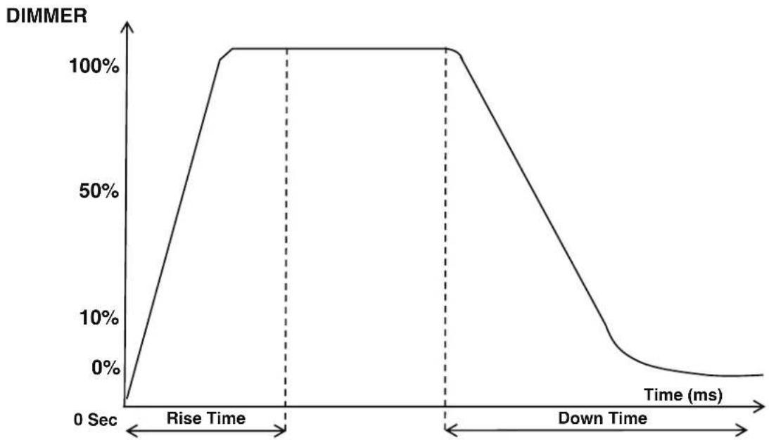
DIM MODES
line
| Time (ms) | DIMMER | | --------- | ------ | | 0 | 0% | | Rise | 100% | | Down | 0% || Dimming Curve Ramp Effect | 0 sec Fade Time | 1 sec Fade Time | ||
| 0 | 255 | 0 | 255 | |
| Rise Time (ms) | Down Time (ms) | Rise Time (ms) | Down Time (ms) | |
| Standard (default) 0 | 0 0 0 | |||
| Stage 780 1100 1540 | 1660 | |||
| TV 1180 1520 1860 | 1940 | |||
| Architectural 1380 | 1730 2040 2120 | |||
| Theatre 1580 1940 | 2230 2280 | |||
| Stage 2 0 1100 0 1660 | ||||
line
| DMX % | Output | |-------|--------| | 0 | 0 | | 100 | 100 |
line
| DMX % | Output | |-------|--------| | 0 | 0 | | 100 | 100 |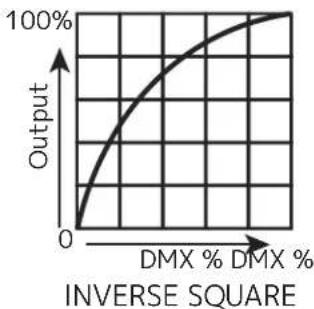
line
| DMX % | Output | |-------|--------| | 0 | 0 | | > DMX % | 100% |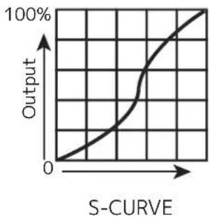
line
| S-Curve | Output | | ------- | ------ | | 0 | 0 | | >0 | 100% |PRIMARY-SECONDARY SET UP
This function allows you to link units together to run in a Primary-Secondary set-up, in which one unit will act as the controlling unit and the others will react to the controlling unit's built-in programs. Any unit can be configured to act as a Primary or as a Secondary, but only one unit in a given system can be programmed to act as the Primary.
Primary-Secondary Connections and Settings:
- Daisy chain your units via the XLR connectors on the rear panels of each unit. Use standard XLR data cables to link your units together. Remember that the male XLR connector is the input and the female XLR connector is the output. The first unit in the chain (primary) will use the female XLR connector only. The last unit in the chain will use the male XLR connector only.
- Use the display screen and control panel to navigate to Personality > Primary/Secondary Mode. Select this sub-menu using the SETUP button, and use the UP and DOWN buttons to toggle between "Primary" and "Secondary". Press SETUP to confirm your selection.
- Repeat Step 2 for each unit in the system. Make sure that only one unit is designated as the Primary, while all other units are designated as Secondaries.
- The secondary units will now follow the behavior of the primary unit.
NOTES:
- Only one unit should be configured as the primary, while all the other units should be configured as secondaries.
- All units should be set to the same DMX channel mode.
- If fixtures fail to sync, verify that all settings mentioned above are the same, then power all devices off, then switch them on again to re-establish the link.
MULTI UNIT POWER LINKING
This features allows you to connect the fixtures to one another using the power cable input and output sockets.
The maximum number of units that can be linked in this manner is as follows:
• 26 units when running on 120V power.
- 50 units when running on 230V power.
DO NOT EXCEED THIS MAXIMUM NUMBER WHEN POWER LINKING UNITS!
All linked units must be of the same make and model type. Do not mix and match units!
MAINTENANCE GUIDELINES

DISCONNECT POWER BEFORE PERFORMING ANY MAINTENANCE!
CLEANING
Frequent cleaning is recommended to ensure proper function, optimized light output, and an extended life. The frequency of cleaning depends on the environment in which the fixture operates: damp, smoky, or particularly dirty environments can cause greater accumulation of dirt on the fixture's optics. Clean the external lens surface regularly with a soft cloth to avoid dirt/debris accumulation.
NEVER use alcohol, solvents, or ammonia-based cleaners.
MAINTENANCE
Regular inspections are recommended to ensure proper function and extended life. There are no user serviceable parts inside this fixture. Please refer all other service issues to an authorized ADJ service technician. Should you need any spare parts, please order genuine parts from your local ADJ dealer.
Please refer to the following points during routine inspections:
A. A detailed electrical check by an approved electrical engineer every three months, to make sure the circuit contacts are in good condition and prevent overheating.
B. Be sure all screws and fasteners are securely tightened at all times. Loose screws may fall out during normal operation, resulting in damage or injury as larger parts could fall.
C. Check for any deformations on the housing, color lenses, rigging hardware, and rigging points (ceiling, suspension, trussing). Deformations in the housing could allow for dust to enter into the fixture. Damaged rigging points or unsecured rigging could cause the fixture to fall and seriously injure a person(s).
D. Electric power supply cables must not show any damage, material fatigue, or sediments.
NEVER remove the ground prong from the power cable.
DIMENSIONAL DRAWINGS
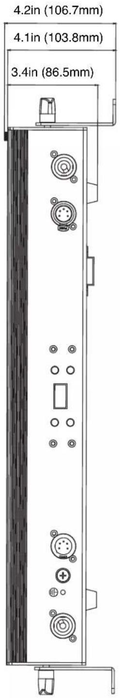
text_image
3.4in (86.5mm) 4.1in (103.8mm) 4.2in (106.7mm)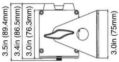
text_image
3.5in (89.4mm) 3.4in (86.5mm) 3.0in (76.3mm) 3.0in (75mm)
other
| Dimension | Value | | ----------------- | ----------- | | Height (in mm) | 2.6 | | Width (in mm) | 3.9 | | Total Length | 20.2 | | Total Width (mm) | 22.4 |SPECIFICATIONS
Light Source:
- 6 x 20W Ultra bright (Red, Green, Blue, Amber, Lime and UV) LEDs
- Long Life LEDs (Rated at approximately 50,000 hrs.)
- 17^ beam angle
• CRI >90 - Pixel Pitch: 85.5mm
Features:
- Linear Color Temperature Control (2,300K to 9,900K)
- Smooth RGBAL+UV color mixing
- Horizontal Magnetic Alignment feature (Built-In)
- Compatible with the ADJ UC-IR24 remote. Operates at a distance of up to 32.8 feet (10 meters)
- RDM Compatible
Control:
• Linear Color Temperature Control (2,300K to 9,900K)
- OLED Display with 4-buttons
• 7 DMX Channel Modes: 6, 11, 13, 16, 18, 25, & 28 Channels
• 3 Groups x2 RGBAL+UV LED pixels controllable via DMX in 18, 25 & 28 channel modes
- 5 operational modes: Auto Run, Program Mode, Sound Trigger, RGBAL+UV Manual, and DMX-512 Mode
• LED Refresh Rate: 1.9KHz
• 64 built-in Color Macros
- 6 selectable Dim Modes (Standard, Stage, TV, Architectural, Theatre & Stage 2)
- 4 selectable Dim Curves (Square, Linear, Inv. Square & S. Curve)
• Built-In Microphone for sound trigger
• LED pulse and strobe effect
• Electronic Dimming: 0-100
Connections:
- Linkable: DMX via 5-pin XLR cable
- Locking power In/Out to daisy chain power
Electrical:
- Multi-voltage operation: AC 100V-240V 50/60Hz
• Power Draw: 26W - Daisy-chain power link (Up to 26 UBL6H's can be linked @120V and up to 50 UBL6H's can be linked @230V)
- Fuse: 2A 250V
Dimensions / Weight:
- Dimensions (LxWxH): 2.96" x 22.40" x 4.2" (75x568.9x106.7mm)
• Weight: 4.41 lbs./2kg.
Environment:
- Operational Temperature Range: -1°F \~ 113°F (-20°C \~ 45°C)
- Storage Temperature: -22°F \~ 113°F (-20°C \~ 45°C)
Certifications / IP Rating:
• IP20
- CE / ETL / FCC


OPTIONAL ACCESSORIES
| ORDER CODE (US) | ORDER CODE (EU) | DESCRIPTION |
| UBL613 TBD | 1x40° Linear Diffusion Lens |
FCC STATEMENT
Please note that changes or modifications of this product is not expressly approved by the party responsible for compliance could void the user's authority to operate the equipment.
NOTE: This equipment has been tested and found to comply with the limits for a Class A digital device, pursuant to part 15 of the FCC Rules. These limits are designed to provide reasonable protection against harmful interference when the equipment is operated in a commercial environment. This equipment generates, uses, and can radiate radio frequency energy and, if not installed and used in accordance with the instruction manual, may cause harmful interference to radio communications. Operation of this equipment in a residential area is likely to cause harmful interference in which case the user will be required to correct the interference at his own expense.