EVS3 - Unspecified Adj - Free user manual and instructions
Find the device manual for free EVS3 Adj in PDF.

User questions about EVS3 Adj
0 question about this device. Answer the ones you know or ask your own.
Ask a new question about this device
Download the instructions for your Unspecified in PDF format for free! Find your manual EVS3 - Adj and take your electronic device back in hand. On this page are published all the documents necessary for the use of your device. EVS3 by Adj.
USER MANUAL EVS3 Adj
natural_image
Exterior view of a colorful digital display panel with gradient purple-to-pink transition and metal frame (no text or symbols)EVS3
User Manual
©2023 ADJ Products, LLC all rights reserved. Information, specifications, diagrams, images, and instructions herein are subject to change without notice. ADJ Products, LLC logo and identifying product names and numbers herein are trademarks of ADJ Products, LLC. Copyright protection claimed includes all forms and matters of copyrightable materials and information now allowed by statutory or judicial law or hereinafter granted. Product names used in this document may be trademarks or registered trademarks of their respective companies and are hereby acknowledged. All non-ADJ Products, LLC brands and product names are trademarks or registered trademarks of their respective companies.
ADJ Products, LLC and all affiliated companies hereby disclaim any and all liabilities for property, equipment, building, and electrical damages, injuries to any persons, and direct or indirect economic loss associated with the use or reliance of any information contained within this document, and/or as a result of the improper, unsafe, insufficient and negligent assembly, installation, rigging, and operation of this product.

DOCUMENT VERSION
Due to additional product features and/or enhancements, an updated version of this document may be available online.
Please check www.adj.com for the latest revision/update of this manual before beginning installation and/or programming.
| Date | Document Version | Software Version | DMX Channels Notes |
| 09/28/2023 1 | .0 N/A Not Applicable Initial Release. | ||
Europe Energy Saving Notice
Energy Saving Matters (EuP 2009/125/EC)
Saving electric energy is a key to help protecting the environment. Please turn off all electrical products when they are not in use. To avoid power consumption in idle mode, disconnect all electrical equipment from power when not in use. Thank you!
CONTENTS
General Information 4
Limited Warranty (USA Only) 6
Safety Guidelines 7
Maintenance Guidelines 9
Panel Overview 10
LED Module Removal Tool 12
LED Module Removal 13
Handling and Transportation 14
Installation 16
Horizontal Panel Assembly 17
Vertical Panel Assembly 18
Rigging Bar 19
Flat Panel Assembly 23
Horizontal Truss Mount 24
Ground Stack 25
Technical Specifications 26
Optional Components and Accessories 27
GENERAL INFORMATION
INTRODUCTION
Please read and understand the instructions in this manual carefully and thoroughly before attempting to operate this device. These instructions contain important safety and use information.
The ADJ Lighting EVS3 is a rugged LED video panel solution designed for temporary installations that demand stunning visual displays. With a pixel pitch of 3.91mm and a configuration of a 3-in-1 RGB SMD2121 LED, the EVS3 delivers crisp and vibrant images with a pixel density of 128x128, totaling an impressive 65,536 pixels per square meter.
The EVS3 is built for convenience and durability, featuring front and rear serviceability with four easily replaceable video modules on each panel. Its compact size of 19.68" x 19.68" x 2.96" and lightweight construction weighing just 16.5 lbs make it highly portable and easy to handle.
Equipped with corner protectors for added durability during transport and setup, the EVS3 ensures that your investment remains protected. Its exceptional optical ratings include a brightness of 800 NITS and a wide viewing angle of 160° horizontal and 140° vertical at 9.75 ft. The EVS3 also offers versatile control options, supporting various input modes such as Composite, S-Video, Component, VGA, DVI, HDMI, and HD-SDI.
Hang up to 20 EVS3 Video Panels vertically with the VSRB1 (VS1100) Rigging Bar. There are magnets on the top and bottom to temporarily connect panels before latching together allowing a single user to install an entire wall. For added convenience, a range of optional accessories are available, including flight cases, rigging bars, support brackets, and video processors, allowing you to customize and enhance your installation according to your specific needs.
The EVS3 is intended for temporary use only and should not be permanently installed. Elevate your visual experience to new heights with the ADJ Lighting EVS3 LED video panel.
UNPACKING
Every device has been thoroughly tested and has been shipped in perfect operating condition. Carefully check the shipping carton for damage that may have occurred during shipping. If the carton is damaged, carefully inspect the device for damage, and be sure all accessories necessary to install and operate the device have arrived intact. In the event that damage has been found or parts are missing, please contact our customer support team for further instructions. Please do not return this device to your dealer without first contacting customer support. Please do not discard the shipping carton in the trash. Please recycle whenever possible.
GENERAL INFORMATION
Customer Support: Contact ADJ Service for any product related service and support needs. Also visit forums.adj.com with questions, comments or suggestions.
Parts: To purchase parts online visit:
http://parts.adj.com (US)
http://www.adjparts.eu (EU)
ADJ SERVICE USA - Monday - Friday 8:00am to 4:30pm PST
Voice: 800-322-6337 | Fax: 323-582-2941 | support@adj.com
ADJ SERVICE EUROPE - Monday - Friday 08:30 to 17:00 CET
Voice: +31 45 546 85 60 | Fax: +31 45 546 85 96 | support@adj.eu
ADJ PRODUCTS LLC USA
6122 S. Eastern Ave. Los Angeles, CA. 90040
323-582-2650|Fax 323-532-2941|www.adj.com|info@adj.com
ADJ SUPPLY Europe B.V
Junostraat 2 6468 EW Kerkrade, The Netherlands
+31 (0)45 546 85 00 | Fax +31 45 546 85 99
www.americandj.eu | info@americandj.eu
ADJ PRODUCTS GROUP Mexico
AV Santa Ana 30 Parque Industrial Lerma, Lerma, Mexico 52000
+52 (728) 282-7070
CAUTION! There are no user serviceable parts inside this unit. Do not attempt any repairs yourself, as doing so will void your manufacturer's warranty. In the unlikely event your unit may require service, please contact ADJ Products, LLC.
Do not discard the shipping cartoon in the trash. Please recycle when ever possible.
LIMITED WARRANTY (USA ONLY)
A. ADJ Products, LLC hereby warrants, to the original purchaser, ADJ Products, LLC products to be free of manufacturing defects in material and workmanship for a prescribed period from the date of purchase (see specific warranty period on reverse). This warranty shall be valid only if the product is purchased within the United States of America, including possessions and territories. It is the owner's responsibility to establish the date and place of purchase by acceptable evidence, at the time service is sought.
B. For warranty service, you must obtain a Return Authorization number (RA#) before sending the product back—please contact ADJ Products, LLC Service Department at 800-322-6337. Send the product only to the ADJ Products, LLC factory. All shipping charges must be prepaid. If the requested repairs or service (including parts replacement) are within the terms of this warranty, ADJ Products, LLC will pay return shipping charges only to a designated point within the United States. If the entire instrument is sent, it must be shipped in its original package and packaging material. No accessories should be shipped with the product. If any accessories are shipped with the product, ADJ Products, LLC shall incur no liability whatsoever for loss of or damage to any such accessories, nor for the safe return thereof.
C. This warranty is void if the product serial number and/or labels are altered or removed; if the product is modified in any manner which ADJ Products, LLC concludes, after inspection, affects the reliability of the product; if the product has been repaired or serviced by anyone other than the ADJ Products, LLC factory unless prior written authorization was issued to purchaser by ADJ Products, LLC; if the product is damaged because it was not properly maintained as set forth in the product instructions, guidelines and/or user manual.
D. This is not a service contract, and this warranty does not include maintenance, cleaning, or periodic check-up. During the period specified above, ADJ Products, LLC will replace defective parts at its expense with new or refurbished parts, and will absorb all expenses for warranty service and repair labor by reason of defects in material or workmanship. The sole responsibility of ADJ Products, LLC under this warranty shall be limited to the repair of the product, or replacement thereof, including parts, at the sole discretion of ADJ Products, LLC. All products covered by this warranty were manufactured after August 15, 2012, and bear identifying marks to that effect.
E. ADJ Products, LLC reserves the right to make changes in design and/or improvements upon its products without any obligation to include these changes in any products theretofore manufactured.
F. No warranty, whether expressed or implied, is given or made with respect to any accessory supplied with products described above. Except to the extent prohibited by applicable law, all implied warranties made by ADJ Products, LLC in connection with this product, including warranties of merchantability or fitness, are limited in duration to the warranty period set forth above. And all warranties, whether expressed or implied, including warranties of merchantability or fitness, are limited in duration to the warranty period set forth above. The consumer's and/or dealer's sole remedy shall be such repair or replacement as is expressly provided above; and under no circumstances shall ADJ Product, LLC be liable for any loss and/or damage, direct and/or consequential arising out of the use of, and/or inability to use this product.
G. This warranty is the only written warranty applicable to ADJ Products, LLC products, and supersedes all prior warranties and written descriptions of warranty terms and conditions heretofore published.
MANUFACTURER'S LIMITED WARRANTY PERIODS:
- Non-LED Lighting Products = 1-Year (365 Days) (Including Special Effect Lighting, Intelligent Lighting, UV lighting, Strobes, Fog Machines, Bubble Machines, Mirror Balls, Par Cans, Trussing, Lighting Stands, Power/Data Distribution, etc. excluding LED and lamps)
- Laser Products = 1-Year (365 Days) (excluding laser diodes which have a 6-Month Limited Warranty)
- LED Products = 2-Year (730 Days) (excluding batteries which have a 180 Day Limited Warranty)
- NOTE: 2-Year (730 Days) Limited Warranty ONLY applies to product purchased within the United States. StarTec Series = 1-Year (365 Days) (excluding batteries which have a 180 Day Limited Warranty)
• ADJ DMX Controllers = 2 Year (730 Days)
• American Audio Products = 1 Year (365 Days)
SAFETY GUIDELINES
This device is a sophisticated piece of electronic equipment. To guarantee smooth operation, it is important to follow all instructions and guidelines in this manual. ADJ is not responsible for injury and/or damages resulting from the misuse of this panel due to the disregard of the information printed in this manual. Only qualified and/or certified personnel should perform the installation of this panel and all included rigging parts and/or accessories. Only the original included rigging parts and/or rigging accessories for this panel should be used for proper installation. Any modifications to the panel, including to rigging and/or accessories, will void the original manufacturer's warranty and increase the risk of damage and/or personal injury.

PROTECTION CLASS 1 - PANEL MUST BE PROPERLY GROUNDED.

THERE ARE NO USER SERVICEABLE PARTS INSIDE THIS PANEL. DO NOT ATTEMPT TO PERFORM ANY REPAIRS BY YOURSELF, AS DOING SO WILL VOID YOUR MANUFACTURER'S WARRANTY. DAMAGES RESULTING FROM MODIFICATIONS TO THIS PANEL AND/OR THE DISREGARD OF SAFETY INSTRUCTIONS AND GUIDELINES IN THIS MANUAL VOID THE MANUFACTURER'S WARRANTY AND ARE NOT SUBJECT TO ANY WARRANTY CLAIMS AND/OR REPAIRS.

DO NOT PLUG PANEL INTO A DIMMER PACK! NEVER OPEN THIS PANEL WHILE IN USE! UNPLUG POWER BEFORE SERVICING PANEL! NEVER TOUCH FRONT OF PANEL DURING OPERATION, AS IT MAY BE HOT! KEEP FLAMMABLE MATERIALS AWAY FROM PANEL.

INDOOR / DRY LOCATIONS USE ONLY! DO NOT EXPOSE PANEL TO RAIN AND/OR MOISTURE! DO NOT SPILL WATER AND/OR LIQUIDS ON OR INTO THE PANEL!
SAFETY GUIDELINES
- DO NOT touch panel housing during operation. Turn OFF power and allow approximately 15 minutes for panel to cool down before servicing.
- DO NOT operate devices with covers open and/or removed.
- DO NOT shake panel, and avoid brute force when installing and/or operating.
- DO NOT expose any part of the panel to open flame or smoke. Keep panel away from heat sources such as radiators, heat registers, stoves, or other appliances (including amplifiers) that produce heat.
- DO NOT install/use in extremely hot/humid environments, or handle without ESD precautions.
- DO NOT exceed an operation temperature of 40^ (104°F), as doing so will result in damage to the device.
- DO NOT operate if power cord is frayed, crimped, damaged, and/or if any of the power cord connectors are damaged and do not insert into the panel securely and with ease. NEVER force a power cord connector into the panel. If the power cord or any of its connectors are damaged, replace immediately with a new cord and/or connector of the same power rating.
- DO NOT block air ventilation slots/vents. All fan and air inlets must remain clean and never blocked.
- Allow approximately 6" (15cm) between panel and other devices or a wall for proper cooling.
- ALWAYS disconnect panel from main power source before performing any type of service and/or cleaning procedure.
- Only handle the power cord by the plug end, and never pull out the plug by tugging the wire portion of the cord.
- ONLY use the original packaging materials and/or case to transport the panel in for service.
- PLEASE recycle shipping boxes and packaging whenever possible.
- To avoid causing physical damage, read the installation instructions carefully before installation.
- Panels should be installed/operated by qualified and trained professionals ONLY.
• Always mount panels in a safe and stable manner. - INDOOR / DRY location use ONLY! Outdoor use will void the manufacturer's warranty.
- Wear appropriate safety equipment during panel installation.
- Turn OFF power to panel, computers, servers, system boxes, and monitors before making any type of power or data connections and before performing any maintenance work.
- Electronics used in this panel are ESD (Electrostatic Discharge) sensitive. To protect device from ESD, wear a grounded ESD wrist strap or similar grounding device when handling panel.
- Panel must be properly grounded before operating. (resistance must be less than 4 )
- Ensure all power is disconnected from panel before unplugging any data cables from the panel, especially serial line ports.
- Route power and data cables so that they are NOT likely to be walked on or pinched.
• Air conditioning is required if operating environment temperature exceeds 30^ C ( 86^ F). - If panels are not in regular use for an extended period, it is advised to test run the devices for 2 hours each week to ensure that they remain in proper working condition.
- Cases used to transport panel must me properly waterproofed for transportation.
MAINTENANCE GUIDELINES
- Careful and regular maintenance is necessary to optimize the potential functional lifespan of the video panels.
- Read the installation and operation instructions for correct operation of the video panels.
- Although the video panels are designed and built to withstand some impact forces when installed correctly, care should still be taken to avoid impact damage when handling or transporting them, especially at or near the corners and edges of the devices, which are particularly susceptible to damage during transportation.
- The fixture should be serviced by a qualified service technician when:
A. Objects have fallen onto, or liquid has been spilled into, the fixture
B. The fixture has been exposed to rain or water conditions in excess of IP rating parameters for an IP20 device. This includes exposure from the front, rear, or side of the panels.
C. The fixture does not appear to operate normally or exhibits a marked change in performance.
D. The fixture has fallen and/or has been subjected to extreme handling.
- Check each video panel for loose screws and other fasteners.
- If the video panel installation is fixed or displayed for a lengthy time, regularly inspect all rigging and installation equipment, and replace or repair as necessary.
- During long periods of non-use, disconnect the main power to the unit.
- Use necessary ESD (electrostatic discharge) precautions when handling video panels, especially the LED screens, as they are ESD sensitive and easily damaged from ESD exposure.
- The Null Line and Live Line connections from the computer and control system cannot be reversed and should therefore only be connected in original layout order.
- If the GFI (Ground Fault Interrupt) breaker-switch trips often, check the display or replace the power-supply switch.
- When operating the video panels, power up the computer before powering up the video panels. Conversely, when shutting down after operation, turn the video panels off before turning off the computer. If the computer is turned off while the panels are still powered on, a high intensity spike of brightness may occur, resulting in catastrophic damage to the LEDs.
- If a circuit shorts out, a breaker-switch trips, wires burn, and or any other abnormality appears while conducting an electrical test, discontinue testing, and troubleshoot units to find the problem before continuing with any testing or operation.
- To ensure consistent operation, it might be necessary to learn operating parameters for installation, data recovery, backup, controller settings, and basic data preset modification.
- Regularly check computer for any viruses and remove any irrelevant data.
- Only a qualified technician should operate software system.
- Remove any moisture found inside or outside of any video panels before dismantling video installation and returning them to their optional flight cases (sold separately). Ensure flight cases are free of any moisture, using a fan to dry them if necessary, and avoid frictional contact that may result in ESD generation when returning video panels to the flight cases.
- The video panels are designed for indoor use only, within its IP20 rating parameters (front / rear). Limit or remove any unit exposed to moisture, condensation, or humidity, and consider using air conditioning where available.
- When not in use, store video panels in a dry, well ventilated facility.
PANEL OVERVIEW
DIMENSIONS: 19.75" x 19.75" x 3" (500mm x 500mm x 100mm)

text_image
19.75" (500mm) 19.75" (500mm) 3.0" (100mm)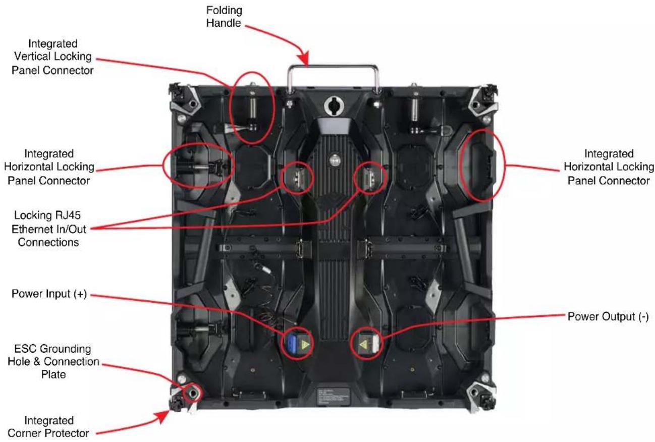
text_image
Folding Handle Integrated Vertical Locking Panel Connector Integrated Horizontal Locking Panel Connector Integrated Horizontal Locking Panel Connector Locking RJ45 Ethernet In/Out Connections Power Input (+) ESC Grounding Hole & Connection Plate Integrated Corner Protector Integrated Power Output (-)PANEL OVERVIEW
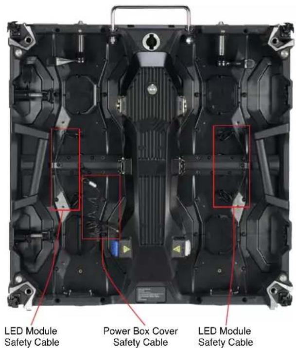
Each video panel includes a quick-release power supply with four (4) LED Modules, allowing for easy serviceability and simple repairs whilst out on the road. Each module is held safely in place with frame integrated magnets. The cover of the power supply box can be secured to protect all internal accessories and components. All detachable components are secured with a safety cable.
text_image
LED Module Safety Cable Power Box Cover Safety Cable LED Module Safety Cable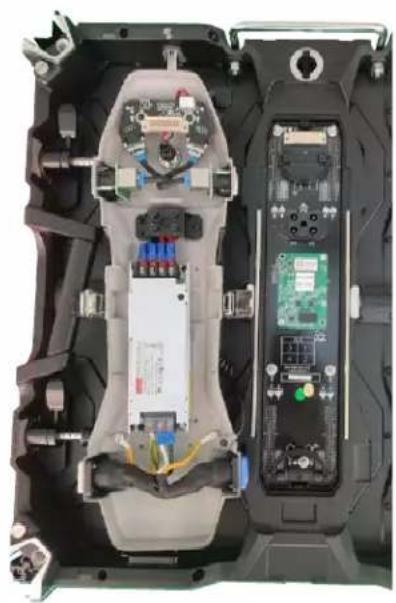
natural_image
Interior view of a device showing internal components including CPU socket, memory card, and drive unit (no visible text or symbols)LED MODULE REMOVAL TOOL
A technician can use the optional Vacuum Module Removal Tool (ADJ part number EVSVAC, sold separately) to safely remove and reinstall any of the four LED Modules in the video panel, and minimize potential damage from mishandling, ESD exposure, or other issues.

text_image
Vacuum Nozzle Trigger Padded Face Airflow KnobThe airflow adjustment knob can be rotated to adjust the amount of vacuum suction force exerted by the tool. Turn the knob clockwise to increase suction force, or counter-clockwise to decrease suction force.

The face of the tool is padded to cushion against damaging the LED modules. Nevertheless, use caution and do not use excessive force when pressing the vacuum tool against the LED module.
LED MODULE REMOVAL
Note that the (4x) LED Modules are firmly held to the video panel frame with strong integrated magnets, and each individual LED module is secured with its own safety cable.

natural_image
Top-down view of a black electronic device chassis with visible internal components and mounting brackets (no text or symbols)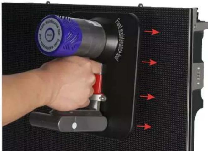
natural_image
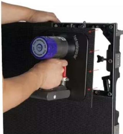
Hand inserting a device into a black panel with red arrows indicating force application (no text or symbols on device)Detach the safety cable for the LED module that you wish to remove. The above left image, for example, shows the location of the safety cable for the upper left LED module. Next, gently press the cushioned face of the vacuum tool to the front of the LED module, as shown in the above right image, and press and release the trigger. Please note that you do not need to continuously hold the trigger to maintain suction.
natural_image
Close-up of a hand holding a black electronic device with a blue and red component, mounted on a dark panel (no visible text or symbols)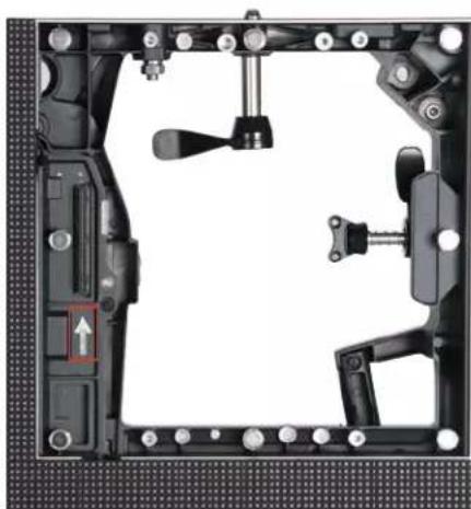
natural_image
Mechanical assembly diagram showing frame components and a highlighted movement arrow (no text or symbols)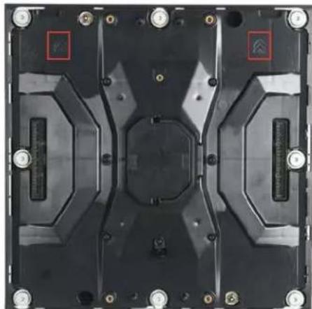
natural_image
Top-down view of a black electronic component with mounting holes and internal structural elements (no visible text or symbols)Pull the LED module away from the video panel frame, as shown in the above left image. Grasp the freed LED module securely with your free hand, then press and release the trigger on the vacuum tool to disengage suction. When re-assembling, ensure that the arrow on the frame (above center) is aligned in the same direction as the arrows on the back of the LED module (above right).
HANDLING AND TRANSPORTATION
INTEGRATED CORNER PROTECTORS
The corners of the video panels are susceptible to damage during handling and transportation. When removing the video panels from their respective Flight Cases (VSFC8 sold separately), and before they are installed, exercise extra caution to avoid damaging any of the 4 corners.
natural_image
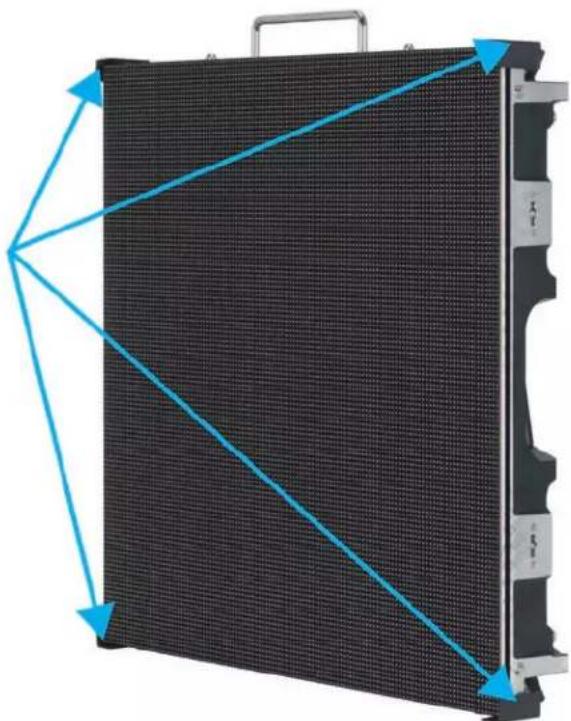
Exterior view of a black LED panel with blue directional arrows indicating orientation (no text or symbols)The integrated corner protectors rotate out of their respective housing pockets to protect the corners during storage or transpotation (below right). During installation, these corner protectors can be rotated back into their housing pockets to allow for the fitment of adjacent panels (below left).

natural_image
Close-up of a mechanical device showing internal components and mounting holes (no text or symbols visible)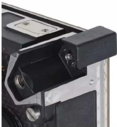
natural_image
Close-up of a mechanical component with black and metallic parts, no visible text or symbolsHANDLING AND TRANSPORTATION
ELECTROSTATIC DISCHARGE (ESD) PRECAUTIONS
Because these are ESD sensitive units, ESD precautions must be observed when removing the video panels from their flight case (ESD gloves, protective clothing, wrist straps, etc.). In addition to using standard ESD precautions, in order to reduce static building friction, take care to lift the panels without rubbing the LED panel surface along the foam-covered slots, which can generate static electricity that can damage LEDs.
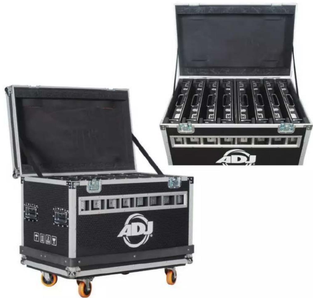
FLIGHT CASE
The optional VSFC8 Flight Case (sold separately) holds eight (8) individual video panels. The flight case features a full foam lining with slots for each unit. The case is robust, offering complete protection for a set of panels on the road. Designed specifically for use with these video panels, it is constructed from 9mm plywood and fitted with steel ball corners, aluminum edging, large swivel castors, professional butterfly latches, four sprung handles, and a hinged lid.
natural_image
Two ADJ audio equipment cases with open doors, one open and one closed, both featuring a black and silver frame (no visible text or symbols)INSTALLATION

DO NOT INSTALL THE PANEL IF YOU ARE NOT QUALIFIED TO DO SO!
INSTALLATION BY QUALIFIED TECHNICIANS ONLY!
INSTALLATIONS SHOULD BE CHECKED BY A QUALIFIED PERSON AT LEAST ONCE A YEAR!

FLAMMABLE MATERIAL WARNING
Keep panel(s) a minimum of 5.0 feet (1.5m) away from flammable materials and/or pyrotechnics.

ELECTRICAL CONNECTIONS
A qualified electrician should be used for all electrical connections and/or installatons.

A MAXIMUM OF 15 PANELS (20 PANELS if VS1RSB rear support brackets are used) may be suspended from/stacked upon each other in a vertical column. There is no limit on the number of panels that may be installed in a single horizontal row. Note that additional processing power may be necessary to operate larger quantities of panels.

USE CAUTION WHEN POWER LINKING PANELS OF DIFFERENT MODEL TYPES, AS POWER CONSUMPTION CAN VARY WITH MODEL TYPE, AND MAY EXCEED THE MAX POWER OUTPUT OF THIS PANEL. CONSULT THE SILK SCREEN FOR MAX CURRENT RATING.
| Input Power AC 100-240VAC, 50/60Hz, 16A Max |
| Output Power AC 100-240VAC, 50/60Hz, 14A Max |
| Max Power Consumption 120W Max, 48W Average |
- WARNING! The safety and suitability of any lifting equipment, installation location/platform, anchoring/rigging/mounting method and hardware, and electrical installation is the sole responsibility of the installer.
- Panel(s) and all panel accessories and all anchoring/rigging/mounting hardware MUST be installed following all local, national, and country commercial electrical and construction codes and regulations.
- Before rigging/mounting a single panel or multiple interconnected panels to any metal truss/structure, a professional equipment installer MUST be consulted to determine if the metal truss/structure or surface is properly certified to safely hold the combined weight of the panels(s), clamps, cables, and all accessories.
- Inspect metal truss/structure visually to ensure it does not flex and/or become deformed due to the weight of the panel(s). Damage caused to panel(s) by mechanical stress is not covered by warranty.
- Panel(s) should be installed in areas outside walking paths, seating areas, and areas where unauthorized personnel might reach the panel(s) by hand. Access under work area must be blocked.
- NEVER stand directly below the panel(s) when rigging, removing, or servicing.
• OVERHEAD RIGGING: Overhead fixture installation must always be secured with a secondary safety attachment, such as an appropriately rated safety cable. Overhead rigging requires extensive experience, including calculating working load limits, knowledge of the installation material being used, and periodic safety inspection of all installation material and the fixture itself, among other skills. If you lack these qualifications, do not attempt the installation yourself. Improper installation can result in bodily injury and property damage.
HORIZONTAL PANEL ASSEMBLY

natural_image
Close-up of a mechanical component with a metallic shaft and mounting bracket (no visible text or symbols)- The horizontal tab-keyed connector is spring loaded.

natural_image
Close-up of a mechanical component with a finger pressing a button, showing no visible text or symbols.- Press the horizontal tab-keyed connector until the tab-key passes through the tab-keyed socket.
natural_image
Close-up of a hand pressing a lock mechanism on a black mechanical component (no text or symbols visible)- Rotate the handle to the right (clockwise) to hold the horizontal tab-keyed connector in place.
natural_image
Close-up of a hand pressing a black mechanical component with a red arrow indicating the lock mechanism (no text or symbols visible)- Rotate handle downward (counter-clockwise) to cinch the horizontal tab-keyed connector.

natural_image
Close-up of a hand pressing a black mechanical component with a red arrow indicating rotation (no text or symbols visible)- To unlock, rotate handle clockwise, releasing the tension of the horizontal tab-keyed connector cinching mechanism.
VERTICAL PANEL ASSEMBLY
The maximum number of panels that can be hung/stacked vertically is 15 panels (20 when supported by VS1RSB Rear Support Brackets).

text_image
LOCK ↔ OPEN- Align the vertical positional posts with their corresponding alignment holes.
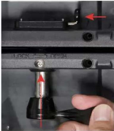
text_image
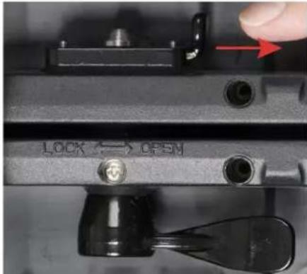
LOCK → OPEN- Press the spring-loaded locking latch toward the left while pressing the vertical connector upwards into the locking latch.
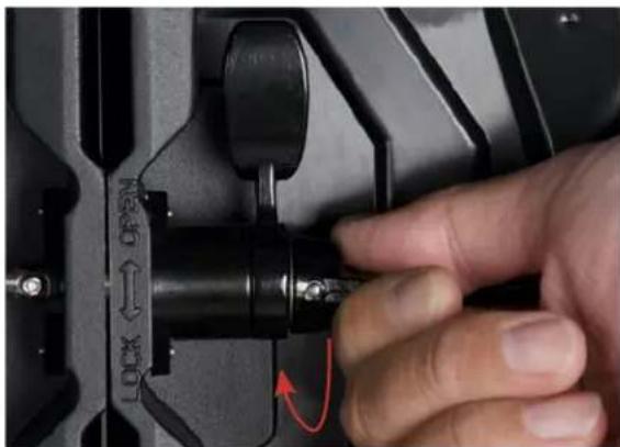
text_image
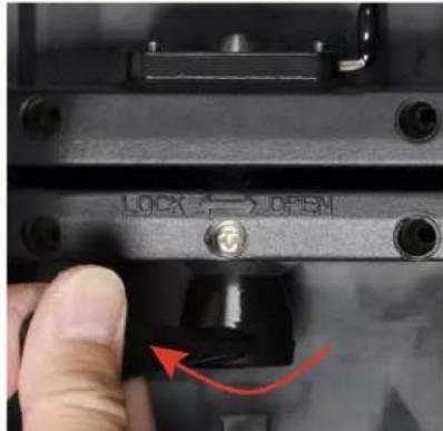
LOCK ↔ OPSN- Release the latch, then lock the panel in place by twisting the vertical connector lever to the left, towards the direction marked "LOCK".
text_image
LOCK ↔ OPEN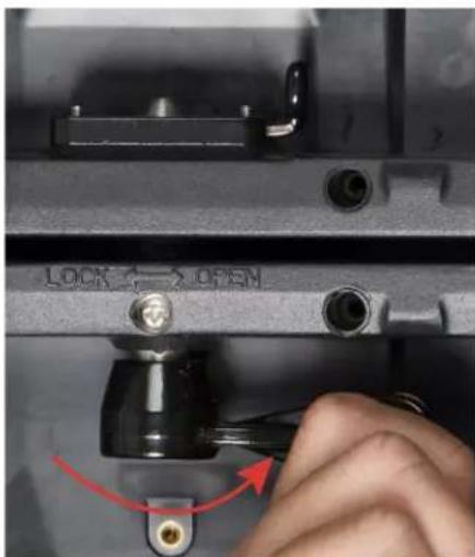
text_image
LOCK ↔ OPEN
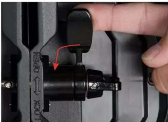
text_image
LOCK ↔ OPEN- To unlock, twist the vertical connector lever to the right, towards the direction marked "OPEN". The locking post will then drop out of place. Press the latch to the left if needed to help release the locking post.
RIGGING BAR
The video panel is compatible with ADJ's VSRB1 Rigging Bar (sold separately), which easily and securely locks to the top of the first panel in a vertical column of up to 15 video panels (20 panels when supported by VS1RSB rear support brackes), allowing them hang from a truss, hoist, or lintel beam. A qualified technician or trained professional is required to fly the VSRB1 Rigging Bar/Video Panel assembly.
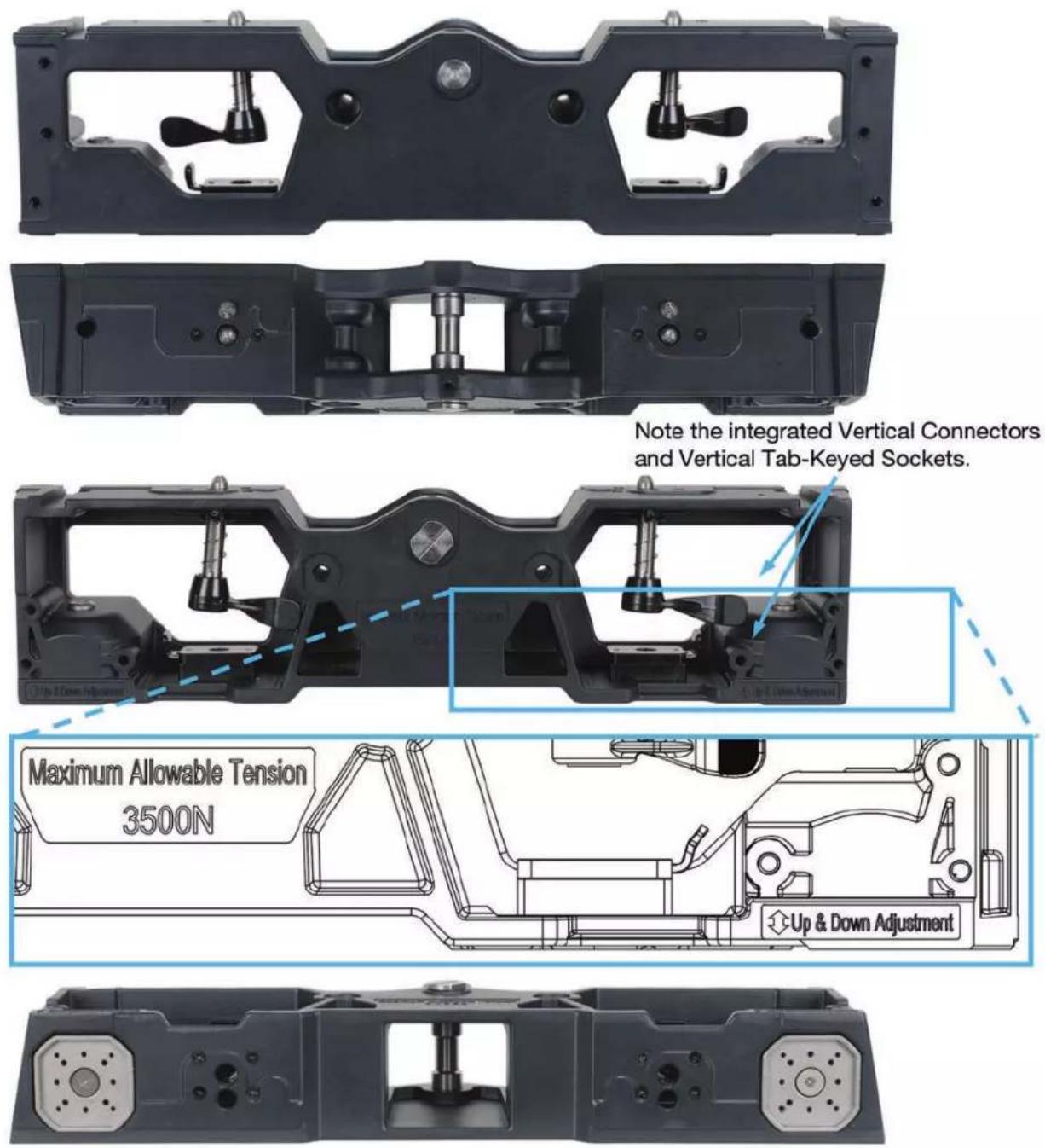
Note the integrated Vertical Connectors and Vertical Tab-Keyed Sockets.
RIGGING BAR
Vertical "hang" and "stack" configurations are illustrated below with the rigging bar.
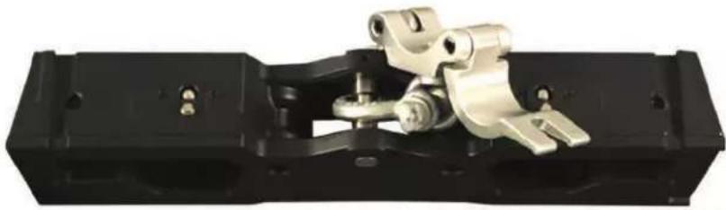
natural_image
Mechanical assembly component with metallic components and black housing (no visible text or symbols)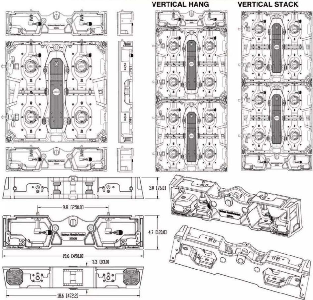
text_image
VERTICAL HANG VERTICAL STACK 3.0 [76.0] 9.8 [250.0] 4.7 [120.0] 19.6 [498.0] 3.3 [83.0] 18.6 [472.2]RIGGING BAR
VERTICAL HANG CONFIGURATION - The maximum number of panels that can be hung vertically is 15 panels (20 when supported by VS1RSB Rear Support Brackets).
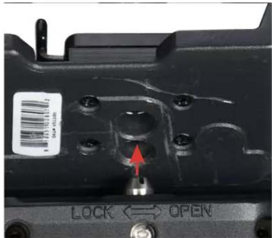
text_image
LOCK ↔ OPEN- Align the vertical positional posts with their corresponding alignment holes.
text_image
Maximum Allowable 3500N Up & Down Adjustment Lock & Open- Press spring-loaded locking latch to the right while pressing vertical connector up into locking latch.

text_image
Maximum Allowable 3500V C-Up & Down AQUISUM LOCK OFF OPEN OPEN- Release latch to hold the vertical connector, and twist vertical connector the left to lock.
text_image
Maximum Allowable 3500N Crip & Down Adjustment 12.0x 0.5mm
text_image
Maximum Allowable 3500N Up & Down Adjustment LOCK ON OPEN
text_image
Maximum Allowable 3500N Up & Down Attachment LOCK: OFF, OPEN- To unlock the vertical connector, rotate the lever to the right (counter-clockwise), then press the spring-loaded locking latch inward. The vertical connector will then drop open.
RIGGING BAR
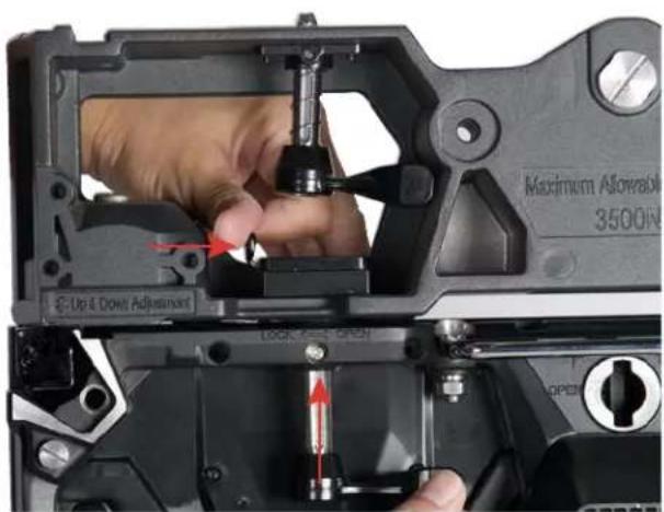
VERTICAL STACK CONFIGURATION - The maximum number of panels that can be stacked vertically is 15 panels (20 when supported by VS1RSB Rear Support Brackets).

natural_image
Close-up of a mechanical assembly showing a bolted component inserted into a housing, with a red arrow indicating the direction (no text or symbols visible)- Align the vertical positional posts with their corresponding alignment holes, then insert the posts into the holes.

natural_image
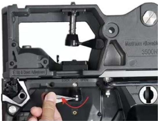
Close-up of hands installing a mechanical component with red arrows indicating assembly or repair (no text or symbols visible)- Press spring-loaded locking latch to the left while pressing vertical connector upwards into locking latch.

natural_image
Close-up of a hand adjusting a mechanical component with red arrows indicating motion (no text or symbols visible)
natural_image
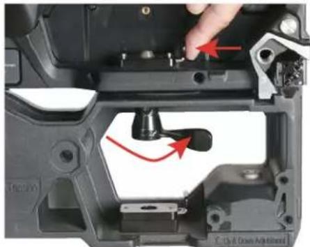
Close-up of a hand using a tool to adjust a component, showing a red curved arrow indicating rotation (no text or symbols visible)- Release latch to hold the vertical connector. Lock in place by twisting the vertical connector to the left.
natural_image
Close-up of a mechanical component with red arrows indicating a turning point (no text or symbols visible)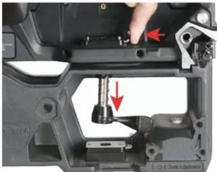
natural_image
Close-up of a mechanical assembly showing a tool inserted into a component, with red arrows indicating direction (no text or symbols visible)- To unlock the vertical connector, rotate the lever to the right (counter-clockwise), then press the spring-loaded locking latch inward. The vertical connector will drop open.

USE CAUTIONS WHEN INSTALLING VIDEO PANELS USING THE RIGGING BAR FOR STACKED ASSEMBLIES. THESE DEVICES ARE NOT INTENDED FOR USE AS A FREE-STANDING ASSEMBLY, AND ARE INHERENTLY UNSTABLE. STACKED VIDEO PANEL ASSEMBLIES MUST BE SECURELY INSTALLED BY A QUALIFIED TECHNICIAN ONLY!
FLAT PANEL ASSEMBLY
Rear Support Bracket: Use an VS1RSB Rear Support Bracket (sold separately) when connecting multiple panels for a larger display design, in order to strengthen the structural integrity of the screen, improve consistent flatness, and improve overall screen continuity.
HORIZONTAL TRUSS MOUNT
The optional VSR210 Horizontal Truss Mounting Bracket (sold separately) allows for the horizontal (ceiling) installation of the VS LED Video Panels.

natural_image
Close-up of a mechanical clamp assembly with red arrows indicating motion, no visible text or symbols
natural_image
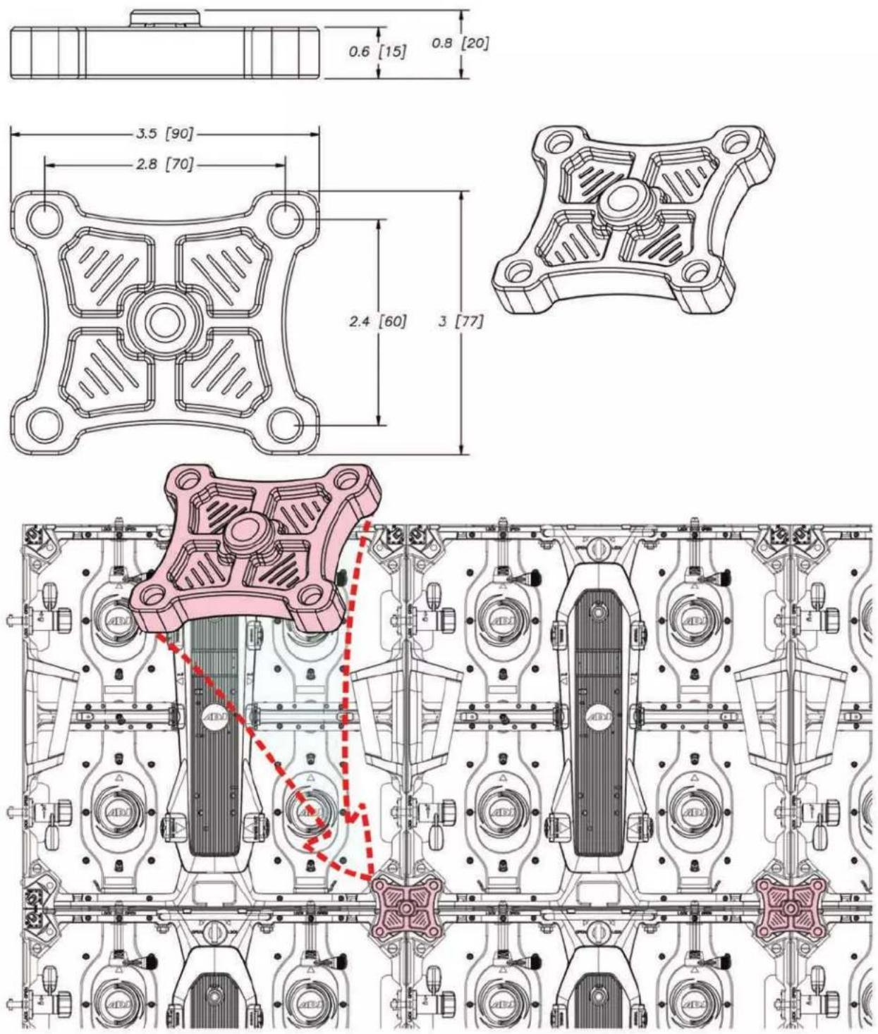
Close-up of a mechanical device with attached black and silver components, no visible text or symbolsGROUND STACK
The optional VSSCSB single panel rigging / ground stack bar is a free-standing stack mounting options for the video panels.
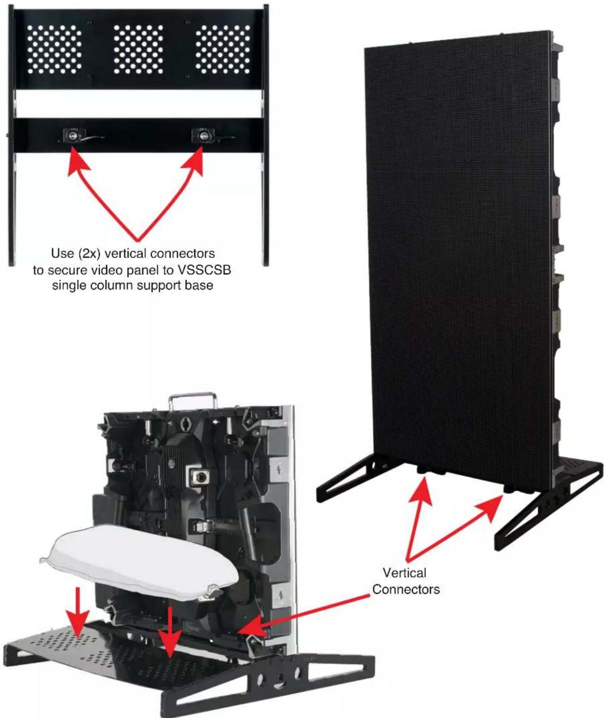
text_image
Use (2x) vertical connectors to secure video panel to VSSCSB single column support base Vertical ConnectorsThe back plate can be loaded with sandbags to stabilize the stacked video panel structure
TECHNICAL SPECIFICATIONS
SPECIFICATIONS:
• Pixel Pitch: 3.91mm (0.15")
• LED Configuration: 3-in-1 SMD2121 LED
• Pixel Density: 128x128; 65536 per square meter
- Size :19.68" x 19.68" x 2.96" / 500 x 500 x 75mm
- Module Quantity: 4
• Weight: 16.5 lbs. / 7.5kg.
FEATURES:
• Corner Protectors to protect the corners of the EVS3 during transport, set-up and teardown
- Front and rear serviceable: 4 easy to replace video modules on each panel
MECHANICAL RATINGS:
• Surface Flatness: Gaps<0.5mm
OPTICAL RATINGS:
- Brightness: 800 NITS
• View Angle: Horizontal 160°/Vertical 140° @ 9.75 ft. (3m) - Gray Scale: ≥14-bit
- Display Color: 256
- Brightness Adjustment: 0\~100% 100 Levels
- Contrast ratio: 5000:1
- Processing: 14-bit
POWER SUPPLY:
• Operation Power: 100\~240V 50-60Hz
• Max. Power Consumption: 120W/per panel
- Ave. Power Consumption: 48W/per panel
- Connections Power/Data: Power-PowerLock In/Out; DataLock In/Out
CONTROL SYSTEM:
• Control Mode: Nova Star Synchronous System with Control via DVI
• Frame Update Frequency: 50-75Hz
- Scan Mode: 1/16
- Refresh Rate: 3840Hz
- Support Input: Composite, S-Video, Component, VGA, DVI, HDMI, HD_SDI
• Control Distance: Ethernet Cable <120m or Fiber Optic>120m
• Support VGA Mode: 1024 x 768, 1280 x 1024, 1600 x 1200, 1920 x 1280
- Brightness Correction: Pixel, Module, Cabinet
ENVIRONMENTAL:
- Operating Temp / Humidity: Fahrenheit: -4^ + 104^ / Celsius: -20^ + 40^/10 - 90% (No Condensation)
- Operating Life / MTBF: 50,000 Hours / 5,000 Hours
• Protection Level: IP20 (Front and Back)
• Out of Control Rate: <0.02%
OPTIONAL ACCESSORIES:
- VSFC8 (VS8100): Flight Case – Fits 8 EVS3 Video Panels
- VSRB1 (VS1100): Rigging Bar – Hang up to 20 EVS3 Video Panels vertically
- VSRQR (VSM210): Quick Rig - Attaches and locks on to the rear of EVS3 so it can be fastened to a 2" pipe or truss
• VS1RSB (VS1126) Rear Support Bracket for EVS3
• VSSCSB VSSCSB): Single Column Support Base
• VSGSB (VSG100): Ground Support Base
• VSGSLT (VSGSLT): Ground Support Ladder Truss
• VSGSCSB (VSG155): Clamp Support Bar
• Novastar VX4S: Video Processor
• Novastar MCTRL-300: Video Processor
• Novastar Nova Pro HD: Video Processor
• Arkaos Media Master: Video Software
• Arkaos GrandVJ 2.0: Video Software
CABLES:
- Cabinet to Cabinet Data Link Cables (Ethernet Locking Connectors)
- Indoor Power Locking Link Cables
- Indoor Power Locking Main Power Cables
CERTIFICATIONS:
• cETLus (Pending)
OPTIONAL COMPONENTS AND ACCESSORIES
| SKU (US) SKU (EU) DESCRIPTION | |
| VS8100 12263001 | 54 VSFC8 Flight Case |
| VS1100 12263001 | 53 VSRB1 Single Panel Rigging/Stack Bar |
| VS1126 12263001 | 58 VS1RSB Rear Support Bracket |
| VSS225 12263001 | 57 VSSCSB Single Column Support Base |
| VSG100 N/A VSG | SB Ground Support Base |
| VSG155 N/A VSG | SCSB Clamp Support Bar |
| VSG132 N/A VSG | SLT Ground Support Ladder Truss |
| VSR210 12263001 | 56 VSRQR Rear Quick Rig Assembly |
| EVSVAC N/A Vac | um Module Removal Tool |
| VX4001 12263000 | 67 Novastar VX4S Video Processor |
| MCT300 12263000 | 034 Novastar MCTRL-3000 Video Processor |
| NOV001 N/A Novastar Nova Pro | HD Video Processor |
| MED500 N/A ArKaos Media Master Express Video Software | |
| MED552 N/A ArKaos Media Master Pro 5 (License) | |
| GRA200 1310000 | 171 ArKaos GrandVJ 2.0 Video Software |
| MED223 N/A ArKaos Studio Server | |
| MED234 N/A ArKaos Stadium Server | |
| MED245 N/A ArKaos 4K Server | |
| MED212 N/A ArKaos Stage Server Pro | |
| MED201 N/A ArKaos Stage Server Express | |
| MPC010 N/A Main Power Cable - | Locking Power Connector In/Out to Edison, 10ft |
| MPC015 N/A Main Power Cable - | Locking Power Connector In/Out to Edison, 15ft |
| MPC025 N/A Main Power Cable - | Locking Power Connector In/Out to Edison, 25ft |
| MPC050 N/A Main Power Cable - | Locking Power Connector In/Out to Edison, 50ft |
| N/A | 1621000113 Main Power Cable IP65 Locking Power - CEE 7/7, 2m |
| N/A | 1621000114 Main Power Cable IP65 Locking Power - CEE 7/7, 5m |
| N/A | 1621000115 Main Power Cable IP65 Locking Power - CEE 7/7, 10m |
| N/A | 1621000116 Main Power Cable IP65 Locking Power - UK, 2m |
| N/A | 1621000117 Main Power Cable IP65 Locking Power - UK, 5m |
| N/A | 1621000118 Main Power Cable IP65 Locking Power - UK, 10m |
| PLC1 | 1621000061 Panel to Panel Power Link Cable - Locking Power Connector In/Out to Locking Power Connector In/Out, 1 ft |
| PLC3 | 1621000101 Panel to Panel Power Link Cable - Locking Power Connector In/Out to Locking Power Connector In/Out, 3 ft |
| PLC6 | 1621000028 Panel to Panel Power Link Cable - Locking Power Connector In/Out to Locking Power Connector In/Out, 6 ft |
| PLC10 | 1621000102 Panel to Panel Power Link Cable - Locking Power Connector In/Out to Locking Power Connector In/Out, 10 ft |
| PLC15 | 1621000103 Panel to Panel Power Link Cable - Locking Power Connector In/Out to Locking Power Connector In/Out, 15 ft |
| PLC25 | 1621000062 Panel to Panel Power Link Cable - Locking Power Connector In/Out to Locking Power Connector In/Out, 25 ft |
| CONTINUED ON NEXT PAGE | |
OPTIONAL COMPONENTS AND ACCESSORIES
| CAT6PRO5 N/A M | Main Data Cable | - Bare RJ45 to Locking RJ45 Ethernet Connection In/Out, 5 ft |
| CAT6PRO10 N/A | Main Data Cable | - Bare RJ45 to Locking RJ45 Ethernet Connection In/Out, 10 ft |
| CAT6PRO15 N/A | Main Data Cable | - Bare RJ45 to Locking RJ45 Ethernet Connection In/Out, 15 ft |
| CAT6PRO25 N/A | Main Data Cable | - Bare RJ45 to Locking RJ45 Ethernet Connection In/Out, 25 ft |
| CAT6PRO50 N/A | Main Data Cable | - Bare RJ45 to Locking RJ45 Ethernet Connection In/Out, 50 ft |
| CAT6PRO100 N/A | Main Data Cable | - Bare RJ45 to Locking RJ45 Ethernet Connection In/Out, 100 ft |
| CAT6PRO150 N/A | Main Data Cable | - Bare RJ45 to Locking RJ45 Ethernet Connection In/Out, 150 ft |
| CAT6PRO25FC N/A | Panel to Panel Data Link Cable - Locking RJ45 Ethernet Connection In/Out to Lock-ing RJ45 Ethernet Connection In/Out, 25 ft | |
| CAT6PRO50FC N/A | Panel to Panel Data Link Cable - Locking RJ45 Ethernet Connection In/Out to Lock-ing RJ45 Ethernet Connection In/Out, 25 ft | |
| CAT6PRO100FC N/A | Panel to Panel Data Link Cable - Locking RJ45 Ethernet Connection In/Out to Lock-ing RJ45 Ethernet Connection In/Out, 25 ft |
This page intentionally left blank.