3370BR - Measurement Daytronic - Free user manual and instructions
Find the device manual for free 3370BR Daytronic in PDF.

User questions about 3370BR Daytronic
0 question about this device. Answer the ones you know or ask your own.
Ask a new question about this device
Download the instructions for your Measurement in PDF format for free! Find your manual 3370BR - Daytronic and take your electronic device back in hand. On this page are published all the documents necessary for the use of your device. 3370BR by Daytronic.
USER MANUAL 3370BR Daytronic
Copyright © 1996, Daytronic Corporation. All rights reserved.
No part of this document may be reprinted, reproduced, or used in any form or by any electronic, mechanical, or other means, including photocopying and recording, or in any information storage and retrieval system, without permission in writing from Daytronic Corporation. All specifications are subject to change without notice.
Correction
to Model 3170 Instruction Manual, v. SB.5.1
The I/O Wiring Data in Fig. 4 of this manual does not give the correct shield pairing of cable wires, which is shown in the revised diagrams below and on the following page:

(cont'd)
Correction
to Model 3170 Instruction Manual, v. SB.5.1 (cont'd)
Daytronic 3X70 Instrument to Generalized Strain Gage Transducer
text_image
A 1 +SENSE 2 -SENSE 3 CAL SENSE 4 SHIELD 9 + EXC 4-Wire Configuration for Cables Shorter Than 20 Feet +SIG -SIG -EXC 6-Wire Configura Shorter Than 20 Feet 1 A +SENSE 28-Wire Configuration for Cables Longer Than 20 Feet
flowchart
graph TD
    A["1"] -->|+SENSE| B["2"]
    A -->|-SENSE| C["3"]
    B --> D["4"]
    C --> E["5"]
    D --> F["6"]
    E --> G["7"]
    F --> H["8"]
    G --> I["9"]
    H --> J["..."]
    I --> K["..."]
    L["SHIELD"] --> M["C"]
    M --> N["A"]
    style A fill:#f9f,stroke:#333
    style B fill:#ccf,stroke:#333
    style C fill:#cfc,stroke:#333
    style D fill:#fcc,stroke:#333
    style E fill:#cff,stroke:#333
    style F fill:#ffc,stroke:#333
    style G fill:#cfc,stroke:#333
    style H fill:#fcc,stroke:#333
    style I fill:#ffc,stroke:#333
    style J fill:#fcc,stroke:#333
    style K fill:#ffc,stroke:#333
    style L fill:#fcc,stroke:#333
    style M fill:#cfc,stroke:#333
    style N fill:#fcc,stroke:#333
    style O fill:#cfc,stroke:#333
    style P fill:#fcc,stroke:#333
    style Q fill:#cfc,stroke:#333
    style R fill:#fcc,stroke:#333
    style S fill:#cfc,stroke:#333
    style T fill:#fcc,stroke:#333
    style U fill:#cfc,stroke:#333
    style V fill:#fcc,stroke:#333
    style W fill:#cfc,stroke:#333
    style X fill:#fcc,stroke:#333
    style Y fill:#cfc,stroke:#333
    style Z fill:#fcc,stroke:#333
    style AA fill:#cfc,stroke:#333
    style AB fill:#fcc,stroke:#333
    style AC fill:#cfc,stroke:#333
    style AD fill:#fcc,stroke:#333
    style AE fill:#cfc,stroke:#333
    style AF fill:#fcc,stroke:#333
    style AG fill:#cfc,stroke:#333
    style AH fill:#fcc,stroke:#333
    style AI fill:#cfc,stroke:#333
    subgraph Extra Wire
        direction TB
        A -->|+SENSE| B
        B -->|+EXC| C
        C -->|+SIG -SIG| D
        D -->|-EXC| E
        E --> F
        F --> G
        G --> H
        H --> I
        I --> J
        J --> K
        K --> L
        L --> M
        M --> N
        N --> O
        O --> P
        P --> Q
        Q --> R
        R --> S
        S --> T
        T --> U
        U --> V
        V --> W
        W --> X
        X --> Y
        Y --> Z
        Z --> AB
6-Wire Configuration for Cables Shorter Than 20 Feet
flowchart
graph TD
    A["1"] -->|+SENSE| B["2"]
    B -->|-SENSE| C["3"]
    C -->|CAL SENSE| D["4"]
    D -->|SHIELD| E["9"]
    E --> F["..."]
    F --> G["..."]
    G --> H["..."]
    H --> I["..."]
    I --> J["..."]
    J --> K["..."]
    K --> L["..."]
    L --> M["..."]
    M --> N["..."]
    N --> O["..."]
    O --> P["..."]
    P --> Q["..."]
    Q --> R["..."]
    R --> S["..."]
    S --> T["..."]
    T --> U["..."]
    U --> V["..."]
    V --> W["..."]
    W --> X["..."]
    X --> Y["..."]
    Y --> Z["..."]
    Z --> AA["..."]
    AA --> AB["..."]
    AB --> AC["..."]
    AC --> AD["..."]
    AD --> AE["..."]
    AE --> AF["..."]
    AF --> AG["..."]
    AG --> AH["..."]
    AH --> AI["..."]
    AI --> AJ["..."]
    AJ --> AK["..."]
    AK --> AL["..."]
    AL --> AM["..."]
    AM --> AN["..."]
    AN --> AO["..."]
    AO --> AP["..."]
    AP --> AQ["..."]
    AQ --> AR["..."]
    AR --> AS["..."]
    AS --> AT["..."]
    AT --> AU["..."]
    AU --> AV["..."]
    AV --> AW["..."]
    AW --> AX["..."]
    AX --> AY["..."]
    AY --> AZ["..."]
    AZ --> BA["..."]
    BA --> BB["..."]
    BB --> BC["..."]
    BC --> BD["..."]
    BD --> BE["..."]
    BE --> BF["..."]
    BF --> BG["..."]
    BG --> BH["..."]
    BH --> BI["..."]
    BI --> BJ["..."]
    BJ --> BK["..."]
    BK --> BL["..."]
    BL --> BM["..."]
    BM --> BN["..."]
    BN --> BO["..."]
    BO --> BP["..."]
    BP --> BQ["..."]
    BQ --> BR["..."]
    BR --> BS["..."]
    BS --> BT["..."]
    BT --> BU["..."]
    BU --> BV["..."]
    BV --> BW["..."]
    BW --> BX["..."]
    BX --> BY["..."]
    BY --> BZ["..."]
MODEL
3170
STRAIN GAGE CONDITIONER
INSTRUCTION MANUAL
Daytronic Corporation
TABLE OF CONTENTS
Section Page
1 Description 1
2 Installation and Cabling 3
3 Calibration 8
4 Block Diagram Description 12
5 Verification of Normal Operation 14
LIST OF ILLUSTRATIONS
Figure Page
1 Model 3170 Strain Gage Conditioner .... 1
2 Instrument Mounting Dimensions 4
3 Instrument Panel Mounting 5
4 I/O Wiring Data 9
5 Front-Panel Description 11
6 Block Diagram 15
7 Star-Bridge Construction 17
LIST OF TABLES
Table Page 1 Specifications 2
PLEASE NOTE: Sections 6 and 7, Figures 8 and 9, and Table 2 have been removed from this manual.
If you need information regarding specific 3170 components and circuitry, please contact the Daytronic Service Department at (937) 293-2566.
INSTRUCTION MANUAL MODEL 3170 STRAIN GAGE CONDITIONER
1. DESCRIPTION
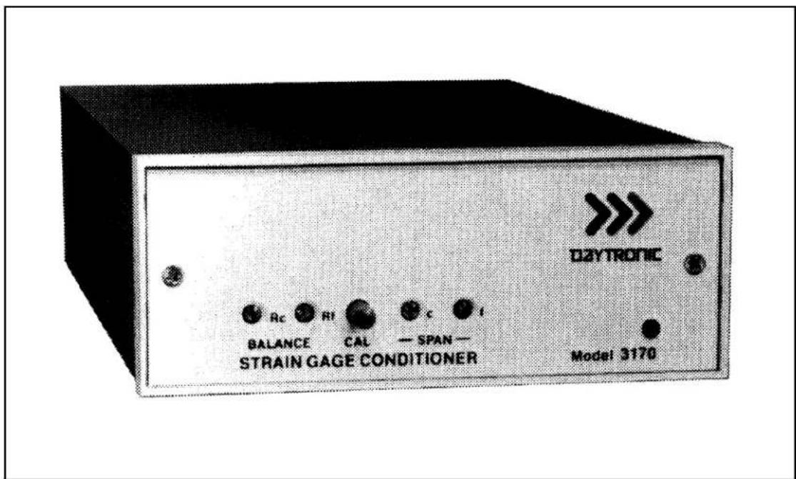
The Model 3170 conditioner-amplifier module for use with resistance strain gage transducers. It supplies a regulated dc excitation voltage to the transducer bridge, provides the necessary balancing and calibration controls, and amplifies the resulting signal to a standard Five-Volt Data Signal Level which is the output analog signal level of 3000 Series Modules. The 3170 has three separate analog outputs, each having a different bandpass: (1) dc to 2 kHz, (2) dc to 200 Hz, and (3) dc to 2 Hz. Active low-pass filters are used to achieve the 200 Hz and 2 Hz cutoff frequencies. The filtered outputs provide for averaging or smoothing signals containing noise or other unwanted dynamic components which are periodic in nature. Filtering removes these dynamic components so that stable digital indication and precise, jitter-free control action can be obtained. The Model 3170 is shown in Figure 1 and the specifications are given in Table 1.
text_image
D2YTRONIC BALANCE CAL SPAN — STRAIN GAGE CONDITIONER Model 3170Figure 1. Model 3170 Strain Gage Conditioner
Table 1. Specifications
| Transducers: 4-arm bridges, 90 to 2000 ohms, nominally 1 to 8 mv/v, full scale (120 ohms or less requires use of 5-volt excitation). |
| Cables: 4-, 5-, or 7-wire, depending on application; 1000 feet maximum length. |
| Bridge Excitation: Regulated 5 volts or 10 volts dc, selected with I/O connector wiring. Transducers with sensitivity from 4 to 8 mv/v full scale must use 5-volt excitation. |
| Balance Adjustments: 10-turn coarse and fine; will balance 1.5 mv/v initial unbalance. |
| Span Adjustments: 10-turn coarse and fine; 1 to 8 mv/v, full scale. |
| Analog Outputs: Three analog outputs available; 0 to ±5 volts with 50% overange, 5 milliamperes maximum. Bandpass is dc to 2 kHz, dc to 200 Hz, or dc to 2 Hz, depending on output used. Active low-pass filters provide for rolloff of 60 dB per decade above cutoff frequency. Full-scale slew time is 1.4/f seconds, where f isthe cutoff frequency. |
| Common Mode Rejection: Greater than 80 dB. |
| Output Ripple and Noise: 0.15% of full scale (rms) maximum for 2-kHz and 100-Hz outputs; 0.02% of full scale (rms) on 2-Hz output. |
| Accuracy: 0.05% of full scale. |
| Dimensions: 1.7 x 4.41 x 8.5 (HWD inches). |
| Operating Temperature Range: 0 to +130 degrees F. |
| Power Requirements: 105 to 135 volts ac, 50 to 400 Hz at 5 watts maximum. |
Daytronic Corporation
Remote sensing techniques are used to regulate the excitation voltage at the transducer. Either a 10-volt or a 5-volt excitation voltage can be selected by appropriate wiring at the module I/O connector. The excitation voltage is protected against overloads and accidental short circuits.
The 3170 uses a CMOS chopper-stabilized differential signal amplifier which has over 100-megohms input impedance per input line. This circuit guarantees negligible drift with temperature variations or component aging.
Calibration of the 3170 is accomplished by the conventional shunt technique, using an internally installed calibration resistor. A front-panel CAL button or Remote Cal terminals on the module I/O connector can be used to initiate the calibration procedure.
The 3170 Strain Gage Conditioner is also available in two additional forms. The Model 3270 includes the addition of a digital indicator to view the analog output of the conditioner. The Model 3370 includes a Limit section (in addition to a digital indicator) which provides high, low, and ok indications and outputs. The digital indicator and limit options are standard to all 3000 Modules and are covered in separate instruction manuals.
2. INSTALLATION AND CABLING
The following paragraphs provide the instructions for module installation and cabling.
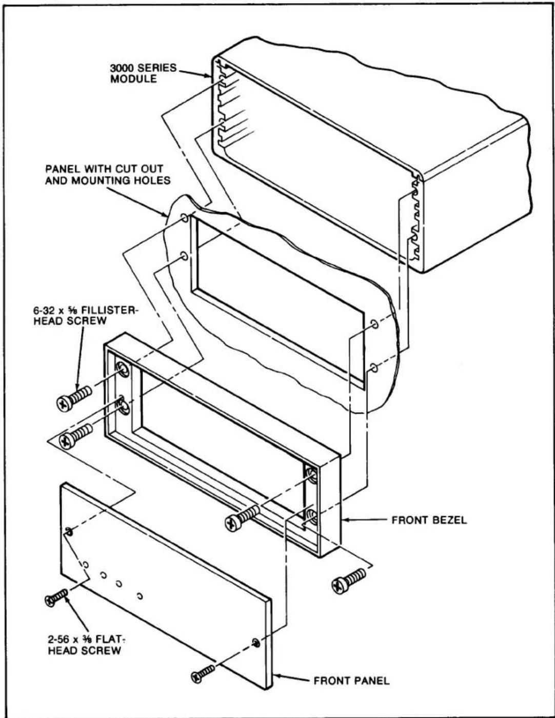
Module Mounting. The 3000 Series Modules can be operated as bench-top instruments or they can be rack- or panel-mounted. Clearance dimensions for a bench-mounted instrument are given in Figure 2. Panel cut-out dimensions for panel mounting are also shown in Figure 2. Up to four 3000 Series instruments can be mounted in a 19-inch rack using the 1.75-inch high Model 3004 Rack Adaptor. Rack-mounting dimensions are also given in Figure 2. To panel mount an instrument, proceed as follows. Refer to Figure 3.
Important: The unit is shipped with two spacer washers on the securing screws of the rear-panel I/O Connector. When panel-mounting the unit, you MUST REMOVE THESE WASHERS, so that the printed-circuit board may move forward about 1/8" during Step (f).
(a) Remove the front panel by removing the two 2-56 x 3/8 flat-head screws.
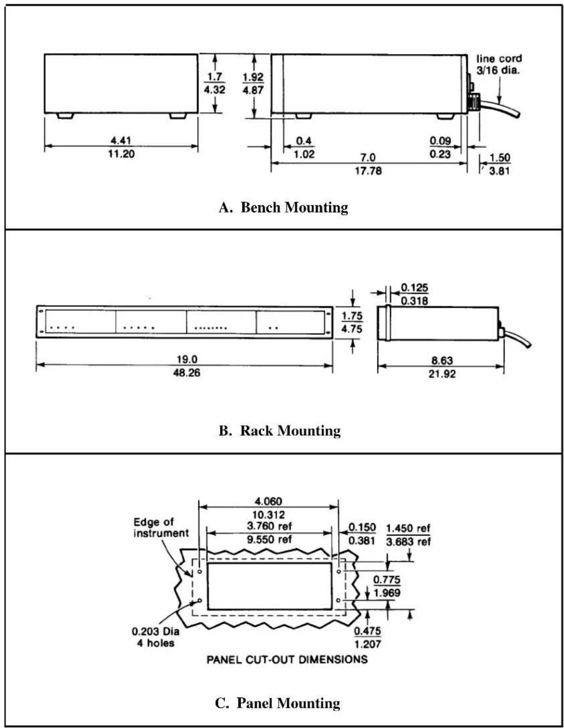
Figure 2. Instrument Mounting Dimensions
text_image
3000 SERIES MODULE PANEL WITH CUT OUT AND MOUNTING HOLES 6-32 x 5/8 FILLISTER- HEAD SCREW FRONT BEZEL 2-56 x 3/8 FLAT- HEAD SCREW FRONT PANELFigure 3. Instrument Panel Mounting
Model 3170
(b) Remove the front bezel by removing the four 6-32 x 5/8 fillister-head screws.
(c) Make the panel cutout and drill the screw clearance holes indicated in Figure 2. The front bezel can be used as a template to define the rectangular cutout and locate the clearance holes.
(d) Hold the module enclosure behind the panel and reattach the front bezel to the enclosure from the front of the panel with the four mounting screws.
(e) Reinstall the front panel.
(f) Tighten the two securing screws of the rear-panel module I/O connector to insure that the connector is seated and that the module printed-circuit board is pushed fully forward so that the front-panel screwdriver adjustments and buttons are accessible. These screws give approximately 1/8-inch of adjustment; consequently, this is the maximum panel width which should be used.
CAUTION
Do not overtighten the connector securing screws or resultant damage may occur to the printed-circuit board.
AC Power Connection. To protect operating personnel, the 3000 Series Modules are equipped with a three-conductor power cord. When the cord is plugged into the appropriate receptacle, the instrument is grounded. The offset pin on the power cord is ground. To maintain the safety ground when operating the module from a two-contact outlet, use a three-prong to two-prong adaptor and connect the green pigtail on the adaptor to ground.
To prepare the module for operation, connect the power cable to a 105-135 volt ac, 50-400 Hz power source. The instrument can use up to 5 watts of power.
Calibration Resistor. If a fixed resistor is shunted across one arm of a strain gage bridge, it produces an unbalance equivalent to that of a particular value of mechanical input. If this Equivalent Input value is accurately known, it can be used as a reference point for shunt calibration of the system. Upon completion of installation of the transducer and its associated cabling, the user can:
Daytronic Corporation
(1) Perform an overall dead weight calibration using a precisely known value of mechanical input. The calibration can then be transferred to the installed shunt calibration resistor for convenience in subsequent checking.
(2) Replace the installed calibration resistor with one (or an equivalent resistance value) supplied by the transducer manufacturer to achieve a precisely known Equivalent Input, allowing the instrument sensitivity to be adjusted correctly.
(3) Determine the Equivalent Input value for the installed calibration resistor, knowing the transducer sensitivity, and adjust the instrument sensitivity accordingly.
A precision 59-kilohm calibration resistor is installed in the 3170 at the factory. The installed resistor can usually be used even though the transducer calibration data mentions some other resistance value. In Section 3 of this manual, the techniques described above are demonstrated. If, however, the installed value of calibration resistor is not appropriate, the 59-kilohm resistor should be replaced at this time by one that is appropriate for the transducer and measurement range to be used. The calibration resistor is mounted on terminals located at the front edge of the strain gage conditioner printed-circuit board. It can be accessed by removing the module front panel.
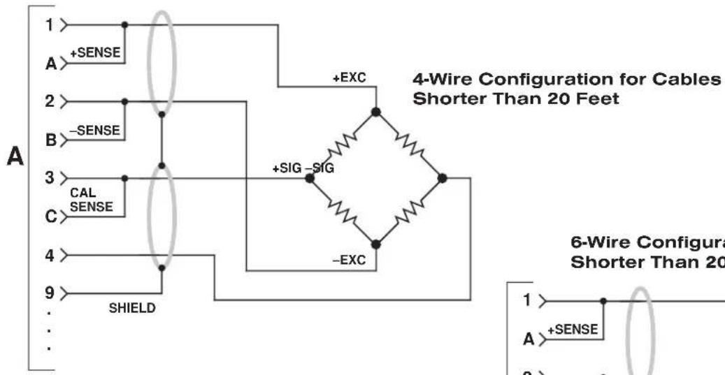
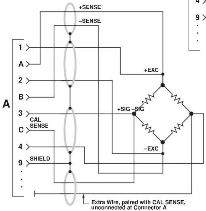
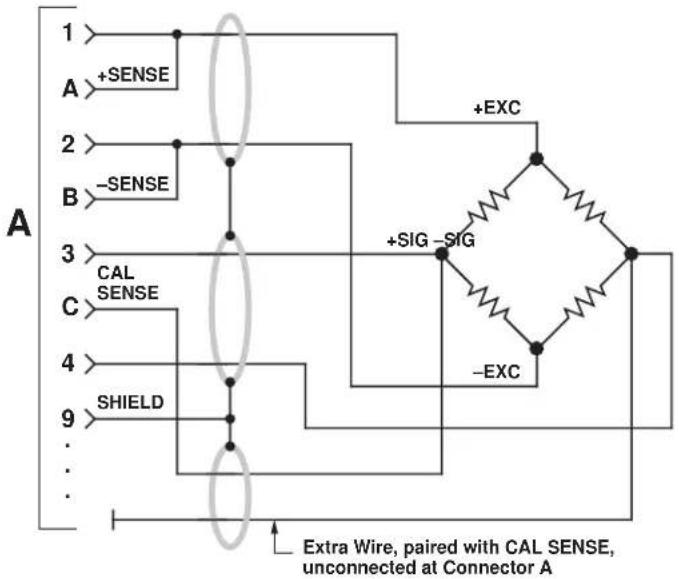
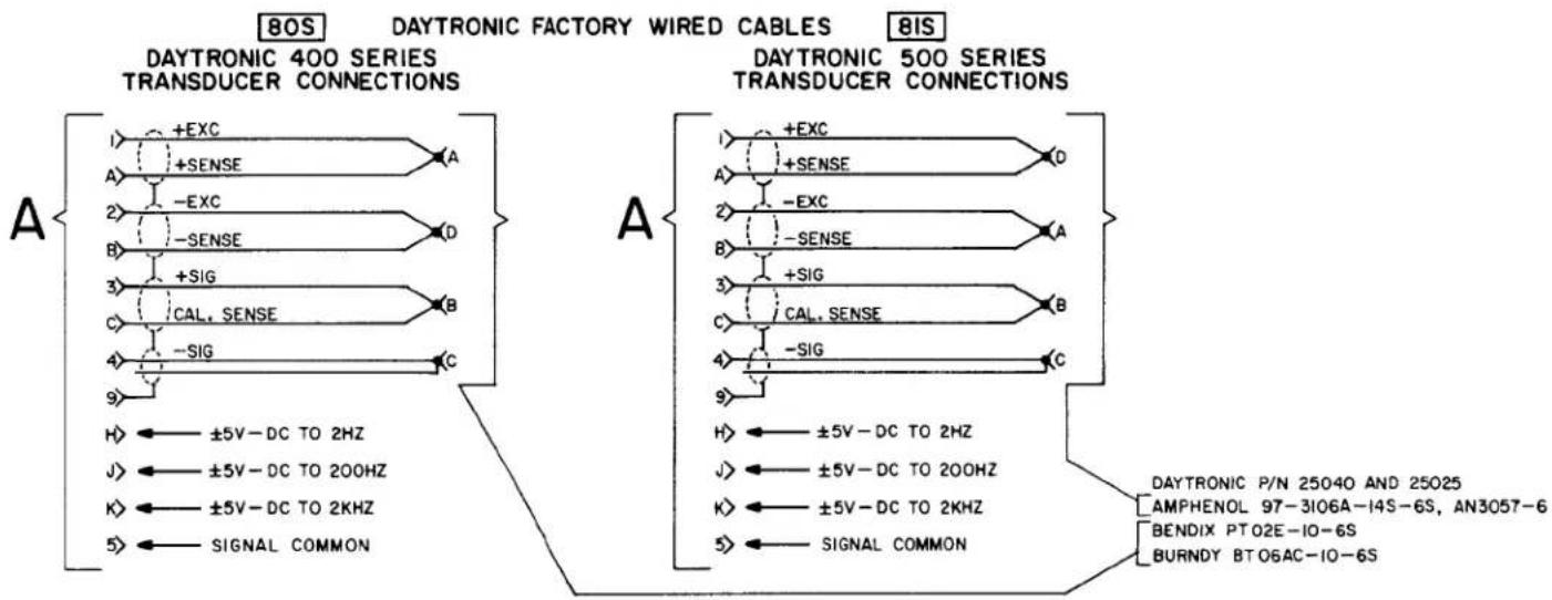
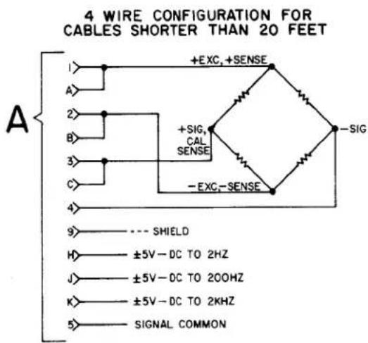
Transducer Cabling. Cabling to the transducer is accomplished via the supplied module I/O connector. The I/O connector pin numbers and functions are given in Figure 4. When Daytronic 400 or 500 Series Transducers are used, factory-wired cables are available as shown in Figure 4. When user-fabricated transducer cabling is used, it should take the form of either the 4-, 5-, or 7-wire cable configuration shown in Figure 4.
The 4-wire configuration should be used when overall dead weight calibration is the method used and the required cable length is less than 20 feet. The 5-wire configuration should be used when the instrument is to be calibrated by achieving a precisely known Equivalent Input value through the use of a shunt calibration resistor (or resistance value) supplied by the transducer manufacturer and when the required cable length is less than 20 feet. The 7-wire configuration should be used with cable lengths longer than 20 feet since the excitation voltage is sensed and regulated at the transducer and optimum shunt calibration can be achieved.
Model 3170
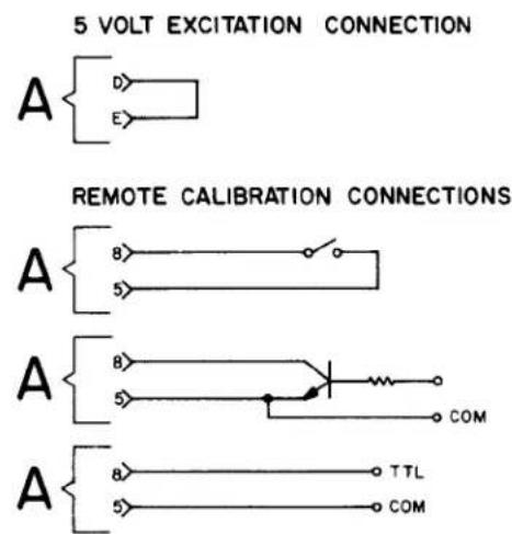
Transducer Excitation. Either 5-volt or 10-volt bridge excitation can be selected. In general, 5-volt excitation is used with 120-ohm transducers, and the 10-volt excitation is used with 350-ohm devices. However, for any transducer which has a 4 mv/v or higher sensitivity, 5-volt excitation must be used to maintain proper operation without saturating the conditioner amplifiers. Five-volt excitation is selected by shorting pins D and E of the module I/O connector (see Figure 4). Ten-volt excitation is achieved when pins D and E are not connected together.
Remote Calibration Check. The instrument can be remotely placed in the calibration mode by shorting pins 5 (Signal Common) and 8 (Remote Cal) of the module I/O connector. Figure 4 indicates three methods of remotely entering the calibration mode through the use of an external switch, transistor, or TTL source. The Remote Cal function provides a convenient method for periodically monitoring calibration of the instrument.
Analog Outputs. Three different analog outputs are available at the module I/O connector. Each output has a different passband: dc to 2 kHz, dc to 200 Hz, and dc to 2 Hz. The 200 and 7 Hz cutoff frequencies are achieved with active low-pass filters. As the cutoff frequency is lowered, a trade off is made between noise elimination and increased time-to-answer or slew time. Each output has a 60-dB rnlloff a decade from the cutoff frequency. The filter characteristics are given by the following equations.
$$ \begin{array}{l} \mathrm{A} _ {\text {out}} @ \mathrm{f} _ {0} = 0. 7 \mathrm{A} _ {\text {in}} \ \mathrm{A} _ {\text {out}} @ 1 0 \mathrm{f} _ {0} = 0. 0 0 1 \mathrm{A} _ {\text {in}} \ \mathrm{T} = 1. 4 / \mathrm{f} _ {0} \ \mathrm{A} _ {\text { in }} = \text { input amplitude } \ \mathrm{f} _ {0} = \text { selected cutoff frequency } \ \end{array} $$
where A_out = output amplitude
T = time-to-answer in seconds (output of filter within 0.1% of final value after step function is applied).
3. CALIBRATION
This section contains the instructions for calibrating the 3170 Included is a functional description of the module front panel (see Figure 5). To perform calibration, proceed as follows.
(a) Turn power ON by placing the rear-panel slide switch in the ON position. The front-panel indicator should light to indicate the application of
Figure 4 I/O Wiring Data
A
DAYTRONIC 3X70 INSTRUMENT I/O CONNECTOR W/PIN DESIGNATIONS (X=1,2,or 3,e.g.3170,3270,or 3370)

AMPHENOL 225-21021-103
REARVIEW
PIN
PIN
1 +EXCITATION
A +SENSE
2 -EXCITATION
B -SENSE
3 + SIGNAL INPUT
C CALIBRATION SENSE
4 - SIGNAL INPUT
D ← CONNECT FOR
5 SIGNAL COMMON
E ← 5V EXCITATION
6 NC
F NC
7 NC
H ANALOG OUTPUT, ±5V-DC TO 2HZ
8 REMOTE CALIBRATION
J ANALOG OUTPUT, ±5V-DC TO 200HZ
9 SHIELD
K ANALOG OUTPUT, ±5V-DC TO 2KHZ
IO OUTPUT SIGNAL COMMON
L NC
flowchart
graph TD
    subgraph_DAYTRONIC_400_Series["DAYTRONIC 400 SERIES TRANSDUCER CONNECTIONS"]
        A1["+EXC"] --> A2["A"]
        A2 --> A3["A"]
        A3 --> A4["-EXC"]
        A4 --> A5["B"]
        A5 --> A6["D"]
        A6 --> A7["+SIG"]
        A7 --> A8["B"]
        A8 --> A9["C"]
        A9 --> A10["-SIG"]
        A10 --> A11["C"]
        A11 --> A12["±5V-DC TO 2HZ"]
        A12 --> A13["J"]
        A13 --> A14["±5V-DC TO 200HZ"]
        A14 --> A15["K"]
        A15 --> A16["±5V-DC TO 2KHZ"]
        A16 --> A17["+SIG"]
        A17 --> A18["C"]
        A18 --> A19["SIGNAL COMMON"]
    end

    subgraph_DAYTRONIC_500_Series["DAYTRONIC 500 SERIES TRANSDUCER CONNECTIONS"]
        B1["+EXC"] --> B2["A"]
        B2 --> B3["A"]
        B3 --> B4["-EXC"]
        B4 --> B5["B"]
        B5 --> B6["+SIG"]
        B6 --> B7["C"]
        B7 --> B8["SIGNAL COMMON"]
        B8 --> B9["H"]
        B9 --> B10["±5V-DC TO 2HZ"]
        B10 --> B11["J"]
        B11 --> B12["±5V-DC TO 200HZ"]
        B12 --> B13["K"]
        B13 --> B14["±5V-DC TO 2KHZ"]
        B14 --> B15["SIGNAL COMMON"]
    end

    style DAYTRONIC_400_Series fill:#f9f,stroke:#333
    style DAYTRONIC_500_Series fill:#bbf,stroke:#333
DAYTRONIC 3X70 INSTRUMENT TO GENERALIZED TRANSDUCER
text_image
4 WIRE CONFIGURATION FOR CABLES SHORTER THAN 20 FEET A 1> +EXC, +SENSE A> 2> +SIG, CAL SENSE B> 3> -EXC, -SENSE C> 4> 9> --- SHIELD H> ±5V-DC TO 2HZ J> ±5V-DC TO 200HZ K> ±5V-DC TO 2KHZ 5> SIGNAL COMMON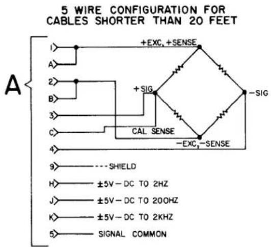
text_image
5 WIRE CONFIGURATION FOR CABLES SHORTER THAN 20 FEET A 1> +EXC, +SENSE A> 2> +SIG B> 3> CAL SENSE C> 4> -EXC,-SENSE 9> ----SHIELD H> ±5V-DC TO 2HZ J> ±5V-DC TO 200HZ K> ±5V-DC TO 2KHZ 5> SIGNAL COMMON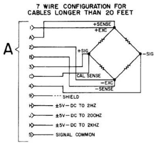
text_image
7 WIRE CONFIGURATION FOR CABLES LONGER THAN 20 FEET A I> +SENSE +EXC 2> +SIG B> CAL SENSE 3> -EXC C> -SENSE 4> ---- SHIELD 9> ±5V-DC TO 2HZ H> ±5V-DC TO 200HZ J> ±5V-DC TO 2KHZ K> SIGNAL COMMON 5>NOTE: Shielding practice as shown above should be followed. Use 4 twisted pairs with individual shields.
Figure 4 (cont'd)
text_image
5 VOLT EXCITATION CONNECTION A D E REMOTE CALIBRATION CONNECTIONS A 8 5 A B 5 COM A 8 5 TTL COM
text_image
BALANCE Controls: The coarse (Rc) and fine (Rf) BALANCE controls are used to set the module output to zero when the transducer is unloaded. SPAN Controls: The coarse (c) and fine (f) SPAN controls are used to set the output to the Equivalent Input value when the CAL button is pressed. CAL Pushbutton: The CAL pushbutton provides for enabling or entering the calibration mode. The Cal resistor is shunted across the + Signal and + Sense terminals when the button is pressed, supplying an Equivalent Input value to the module.Figure 5. Front-Panel Description
ac power. Allow 5 minutes of warm-up for stabilization of transducer characteristics.
(b) With the transducer unloaded, set the module output to zero using the coarse ( R_c ) and fine ( R_f ) BALANCE controls. In some instances, an integral digital indicator will be used to display the conditioner output (Model 3270 or 3370). When only the conditioner is supplied (3170), an external indicator must be used to monitor the conditioner output.
(c) Load the transducer to a convenient up-scale value which is greater than one half of full scale. Adjust the coarse (c) and fine (f) SPAN controls until the output signal causes a reading equal to the dead weight value. Remove the dead weight, then press the CAL button and note the indicator reading obtained. This reading can now be used in future calibrations since it is related to a value obtained thru dead weight
Model 3170
calibration. To calibrate the instrument in the future, simply press the CAL button and adjust the SPAN controls to obtain the reading previously recorded after dead weight calibration.
(d) If dead weight calibration is not practical and the transducer manufacturer has supplied a calibration resistor (or resistor value), install the recommended calibration resistor. Now press the CAL button and adjust the SPAN controls until the module output is equal to the Equivalent Input value simulated by the installed calibration resistor.
If dead weight calibration is not practical and the transducer calibration data is unknown, the Equivalent Input value for the factory-installed calibration resistor can be approximated as follows, assuming that the mv/v sensitivity rating of the transducer and the bridge resistance is known.
$$ \mathrm{X} = \frac {2 5 0 0 0 \mathrm{R} _ {\mathrm{b}}}{\mathrm{KR} _ {\mathrm{c}}} $$
where X = Equivalent Input, % of full scale
R_b = bridge resistance, ohms
K = transducer sensitivity, mv/v full scale
R_c = calibration resistance, ohms (59 K installed)
Sample Calculation: Assume that K = 3.000 mv/v for a 5000-pound load cell (full scale) with a bridge resistance of 350 ohms.
$$ \mathrm{X} = \frac {25000 \times 350}{59000 \times 3} = 49.44 \% \text { of full scale} = 2472 \text { pounds } $$
4. BLOCK DIAGRAM DESCRIPTION
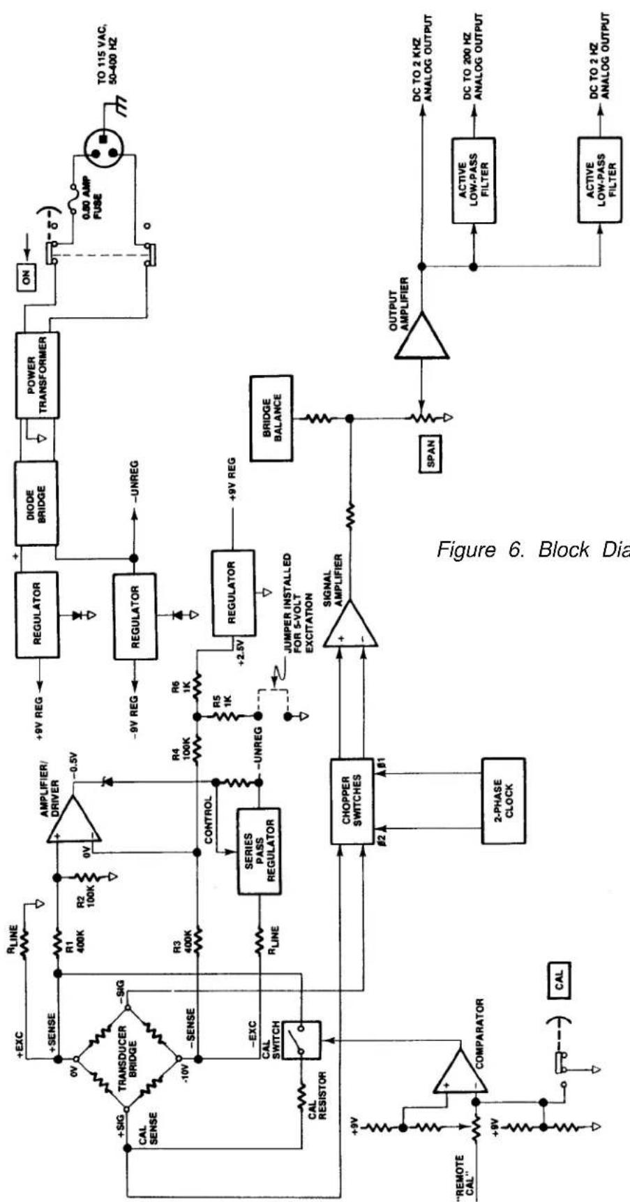
The purpose of this section is to explain how the 3170 works by using a simplified block diagram of the conditioner. This is not intended to be used as a detailed theory of operation discussion for personnel untrained in electronic technology, but as a simplified explanation of the detailed schematic diagram provided with this manual.
Refer to Figure 6. Primary power (115 volts ac, 50-400 Hz) is applied to the module by means of the attached power cable. A rear-panel slide switch is used to turn ON primary power. Overload protection is provided by a 0.25 ampere fuse
Daytronic Corporation
mounted on the conditioner printed-circuit board. When the slide switch is ON, primary power is applied to the power transformer which provides the necessary power-line isolation and the low ac voltages required to develop the regulated dc voltages used in the module. The secondary of the power transformer has a grounded center tap, and a diode bridge functions as two full-wave rectifiers to produce ±9 volts regulated dc. Two three-terminal regulators are used to develop these regulated voltages. The reference terminal of each regulator is biased with one or two diodes to make certain that a minimum regulated voltage of 9 volts is achieved. The proper diode biasing is accomplished at factory check out.
A dc reference voltage of +2.5 volts dc is further developed from regulated +9 volts by the use of a third three-terminal regulator. This precision dc reference is used to bias an amplifier/driver which works in conjunction with a series-pass regulator to regulate the excitation voltage at the transducer bridge. The excitation voltage is normally 10 volts dc, but a jumper can be installed at the module I/O connector to select a 5-volt excitation voltage. The excitation voltage is developed from the minus unregulated side of the diode bridge to more equally balance the current drain on the power transformer secondary. The series-pass regulator has short-circuit protection in the event that the excitation voltage is accidentally shorted at the transducer or module I/O connector.
Figure 6 shows the connections between the transducer bridge and the module made via a 7-wire cable. Optimum accuracy is obtained with the 7-wire configuration since the excitation voltage is regulated at the transducer bridge and a Cal Sense line is returned to the module for accurately setting the Equivalent Input value when the Cal resistor is shunted across one leg of the transducer bridge. The Calibration mode is entered (Cal resistor is shunted across the + Signal and + Sense lines) when the front-panel CAL button is pressed or the Remote Cal input at the module I/O connector is brought to a zero-volt level through the action of an external switch, transistor driver, etc. Either of these actions fires a comparator which, in turn, closes an analog switch in series with the Cal resistor.
The + and - Signal inputs from the transducer bridge are applied to a differential signal amplifier. Each leg of the signal amplifier inputs has approximately 100-megohms input impedance so that no loading is seen by the bridge. The signal amplifier is chopper stabilized to prevent drift which might result from temperature or component aging. A two-phase clock signal synchronized with power line frequency is used as the chopper signal. The differential signal amplifier also provides excellent common-mode rejection.
The bridge balance circuit immediately follows the signal amplifier. The BALANCE and SPAN controls act upon the output of the signal amplifier, not the bridge, to achieve the proper impedance isolation.
Three analog outputs of the conditioned strain gage signal are available at the module I/O connector. The three outputs provide three different passbands of dc to 2 kHz, dc to 200 Hz, and dc to 2 Hz. Output selection is a trade off between eliminating unwanted signals caused by vibration or increasing the time-to-answer (slew rate) of the conditioner. The 200-Hz and 2-Hz cutoff frequencies are achieved with the use of active low-pass filters. The rolloff of each output is 60 dB within a decade of the cutoff frequency.
5. VERIFICATION OF NORMAL OPERATION
It is the purpose of this section to aid the user in determining, in the event of a malfunction to which the Model 3170 is suspected of contributing, whether the module is functioning normally or whether it is a source of the observed trouble. In the event the module requires repair, a complete parts list, schematic diagram, and component location drawing are included in this manual. The user may also contact the factory Service Department or the local Daytronic Representative for assistance.
If the module is suspected of faulty operation, observe the following steps.
(a) If the module is totally inoperational (front panel power indicator does not light), check the primary power fuse (Fl) located on the conditioner printed-circuit board (see Figure 8). If the fuse is blown, replace it with a 0.50 ampere fuse. Before reapplying power, visually inspect the power cord wiring and the printed-circuit board for any discrepancy which could have caused the overload.
(b) If the transducer has some preloading, the BALANCE controls may not allow successful zeroing of the module output. This condition can be remedied by connecting a resistor (50 K-200 K range, metal-film type) from the + Signal terminal of the transducer to the + or - Excitation terminals. The Excitation terminal to which the connection is made is determined by the direction of the loading or off-zero reading.
(c) The inability to balance correctly where the module output reads totally off scale and the BALANCE controls have no authority can very likely be the result of a damaged or defective transducer or cable. This possibil-
flowchart
graph TD
    A[""CAL" --> B[COMPARATOR"]
    B --> C["2-PHASE CLOCK"]
    C --> D["CHOPPER SWITCHES"]
    D --> E["CONTROL"]
    E --> F["SERIES PASS REGULATOR"]
    F --> G["R3 400K"]
    G --> H["+Sense"]
    H --> I["Transducer BRIDGE"]
    I --> J["+SIG"]
    J --> K["CAL SENSE"]
    K --> L["+EXC"]
    L --> M["RLINE"]
    M --> N["+9V REG"]
    N --> O["Regulator"]
    O --> P["DIODE BRIDGE"]
    P --> Q["POWER TRANSFORMER"]
    Q --> R["ON"]
    R --> S["0.80 AMP FUSE"]
    S --> T["TO 115 VAC, 50-400 Hz"]
    T --> U["Output Amplifier"]
    U --> V["DC TO 2 KHZ ANALOG OUTPUT"]
    U --> W["Active LOW-PASS FILTER"]
    W --> X["DC TO 200 Hz ANALOG OUTPUT"]
    W --> Y["Active LOW-PASS FILTER"]
    Y --> Z["DC TO 2 Hz ANALOG OUTPUT"]
    style A fill:#f9f,stroke:#333
    style B fill:#f9f,stroke:#333
    style C fill:#f9f,stroke:#333
    style D fill:#f9f,stroke:#333
    style E fill:#f9f,stroke:#333
    style F fill:#f9f,stroke:#333
    style G fill:#f9f,stroke:#333
    style H fill:#f9f,stroke:#333
    style I fill:#f9f,stroke:#333
    style J fill:#f9f,stroke:#333
    style K fill:#f9f,stroke:#333
    style L fill:#f9f,stroke:#333
    style M fill:#f9f,stroke:#333
    style N fill:#f9f,stroke:#333
    style O fill:#f9f,stroke:#333
    style P fill:#f9f,stroke:#333
    style Q fill:#f9f,stroke:#333
    style R fill:#f9f,stroke:#333
    style S fill:#f9f,stroke:#333
    style T fill:#f9f,stroke:#333
    style U fill:#f9f,stroke:#333
    style V fill:#f9f,stroke:#333
    style W fill:#f9f,stroke:#333
    style X fill:#f9f,stroke:#333
    style Y fill:#f9f,stroke:#333
    style Z fill:#f9f,stroke:#333
Figure 6. Block Diagram
ity can be confirmed (or eliminated) by substituting a transducer and cable known to be in good condition or by simulating a balanced transducer, using either a commercially available transducer simulator or the simple star bridge arrangement shown in Figure 7. The star bridge simulates a conventional four-arm bridge in an exact condition of balance. To construct a star bridge connect four 10% carbon resistors as shown in Figure 7. Use 180-ohm resistors to simulate a 350-ohm bridge and use 56-ohm resistors to simulate a 120-ohm bridge. Neither the resistor values nor temperature characteristics are critical since the balance condition of a star bridge is not determined by the resistance values. Solder two resistors together, then solder the remaining two resistors together. Next, connect the two junctions together using a separate wire as shown. There is a good reason for this method of construction, and it should be followed. Connect the substitute or simulated transducer to the module I/O connector using a short 4-wire cable configuration as shown in Figure 4. Attempt to balance the substitute or simulated transducer. If conditions now appear to be normal, the transducer or cable is at fault. If the previous difficulties persist, the module is faulty.

text_image
USE JUMPER WIRE TO CONNECT 4 RESISTORS MODULE I/O CONNECTOR 1 +EXC A +SENSE - SIG 2 -EXC B -SENSE 3 +SIG C CAL SENSEFigure 7. Star-Bridge Construction
MODEL
3200 / 3300
DIGITAL INDICATOR
INSTRUCTION MANUAL
text_image
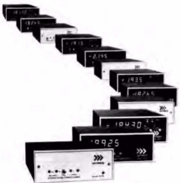
-187135 -18235 +1915 +2.145 +1935 -18265 -18430 -99253000
Instrument Series
MODEL
3200 / 3300
DIGITAL INDICATOR
INSTRUCTION MANUAL
Daytronic Corporation
TABLE OF CONTENTS
Section Page
1 Description 1
2 Installation 4
3 Operation 7
4 Block Diagram Description 8
5 Verification of Normal Operation 15
LIST OF ILLUSTRATIONS
Figure Page
1 3000 Series Instrument with Digital Indicator .... 1
2 Full-Scale Displays for Three Ranges 6
3 Scale, Decimal Point, Dummy Zero Switches 7
4 A/D Converter Timing Diagram 10
5 Block Diagram Description 13
LIST OF TABLES
Table Page
1 3000 Series Model Numbering 2
2 Specifications 4
PLEASE NOTE: Sections 6 and 7, Figures 6 and 7, and Table 3 have been removed from this manual.
If you need information regarding specific 3200/3300 components and circuitry, please contact the Daytronic Service Department at (937) 293-2566.
INSTRUCTION MANUAL 3200/3300 SERIES DIGITAL INDICATOR
1. DESCRIPTION
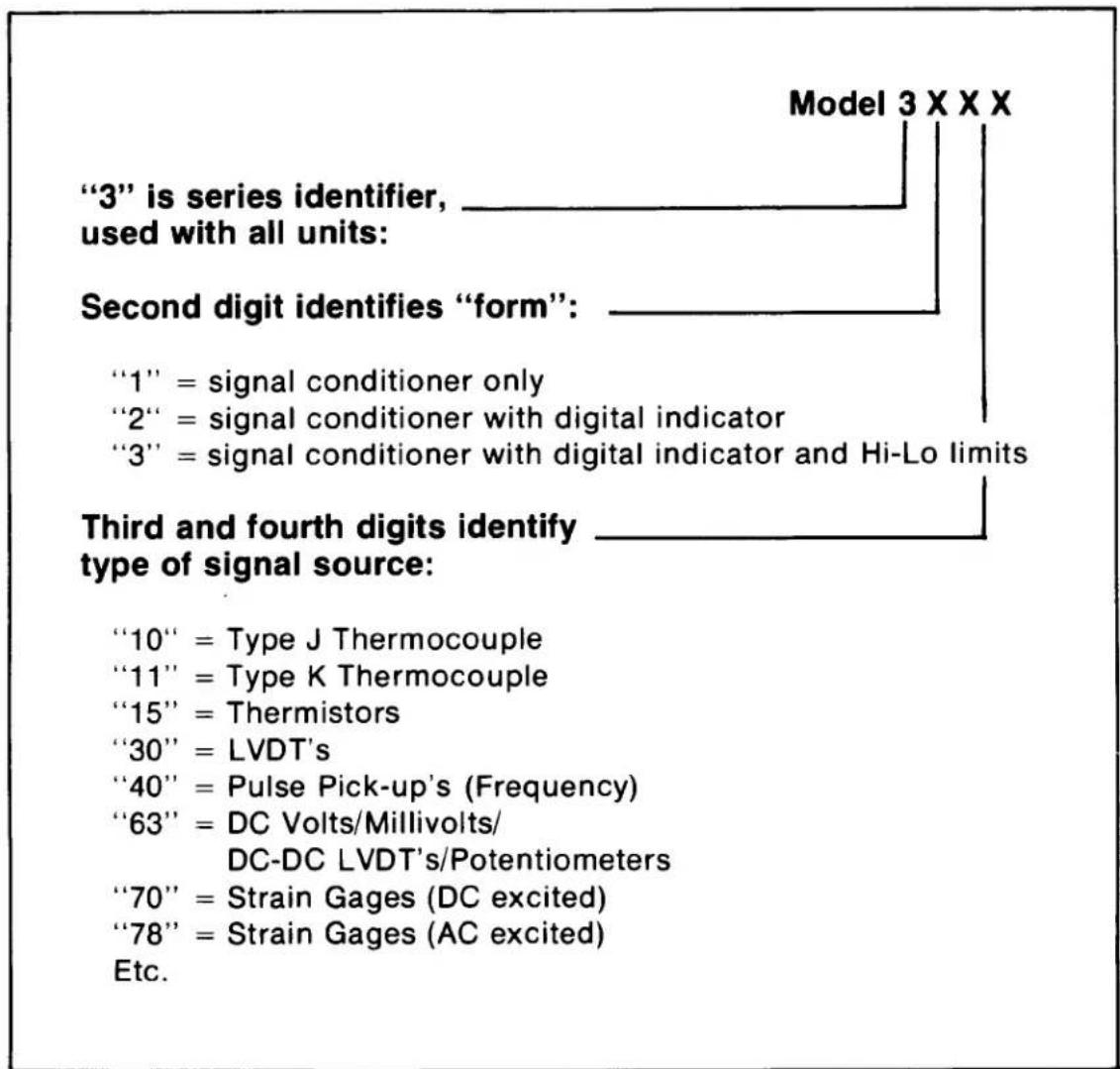
The 3000 Instrument Series is a family of premium signal conditioning instruments that includes models to accommodate virtually all types of transducers and signal sources commonly encountered in electro-mechanical testing and control operations. The 3000 Instruments are available in three forms: Form 1 contains the Signal Conditioner only; Form 2 is the Signal Conditioner with Digital Indicator; Form 3 is the Signal Conditioner with Digital Indicator and Hi-Lo Limits. The Model numbering system used with the 3000 Series identifies the form and the type of signal source. This numbering system is further explained in Table 1. From Table 1, it can be seen that all models having a Digital Indicator are identified by a 32XX or 33XX number, with the last two digits identifying the type of signal source (thermocouple, LVDT, etc).
text_image
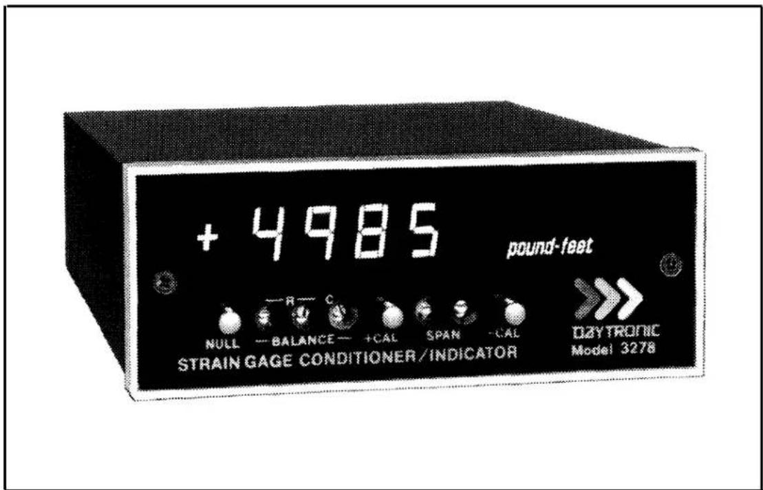
+ 4985 pound-feet NULL — BALANCE — +CAL SPAN — CAL OZYTRONIC STRAIN GAGE CONDITIONER/INDICATOR Model 3278Figure 1. 3000 Series Instrument with Digital Indicator
Table 1. 3000 Series Model Numbering
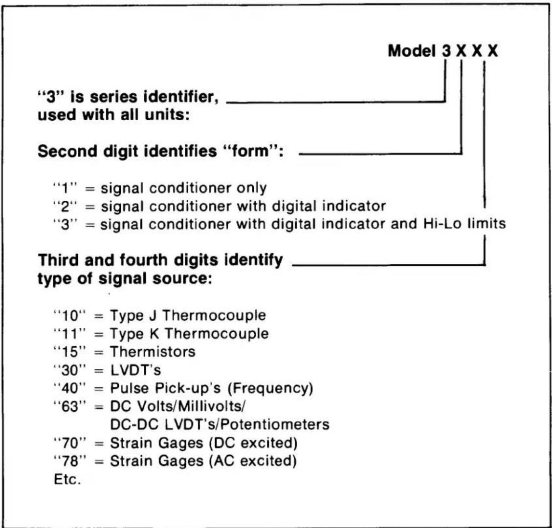
text_image
"3" is series identifier, used with all units: Second digit identifies "form": "1" = signal conditioner only "2" = signal conditioner with digital indicator "3" = signal conditioner with digital indicator and Hi-Lo limits Third and fourth digits identify type of signal source: "10" = Type J Thermocouple "11" = Type K Thermocouple "15" = Thermistors "30" = LVDT's "40" = Pulse Pick-up's (Frequency) "63" = DC Volts/Millivolts/ DC-DC LVDT's/Potentiometers "70" = Strain Gages (DC excited) "78" = Strain Gages (AC excited) Etc. Model 3 X X XThe 3000 Series instruction manual system is designed to provide the user with the following documentation: (1) a separate instruction manual for each type of Signal Conditioner purchased; (2) an instruction manual covering only the Digital Indicator section of a 3000 Series instrument, but applicable to any Form 2 or Form 3 instruments; and (3) an instruction manual covering only the Hi-Lo Limit section
of a 3000 Series instrument, but applicable to any Form 3 instrument. It is the purpose of this manual to cover the Digital Indicator section of all Form 2 and Form 3 instruments.
The Digital Indicator section of any Form 2 or Form 3 instrument consists of a printed-circuit board on which are mounted the required circuit components for digitizing the analog output of the Signal Conditioner and the light-emitting-diode (LED) display. This board is mounted above the circuit board which contains the components for the Signal Conditioner. The digits which comprise the display are mounted on a small board which is affixed to the digitizer board with a right-angle printed-circuit board header. The Form 3 instruments contain an additional printed-circuit board for the Hi-Lo Limit circuitry.
The LED display is comprised of six orange digits with polarity sign. The 0.4 inch height of the digits, combined with the inherent brilliance of an LED type of display, make the display easily discernible in normal room lighting. The display is viewed through the red plastic front panel of the instrument to provide filtering of external light and enhance the display brilliance. The front panel is opaque except for that portion through which the display is viewed. A typical 3000 Instrument with Digital Indicator is shown in Figure 1.
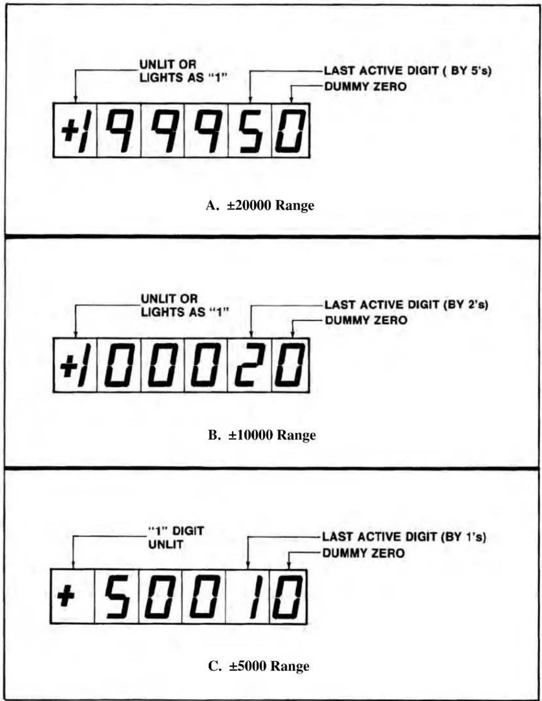
The Digital Indicator scaling is selected with rear-panel pushbutton switches. Full-scale values of ±5000 counted by 1's, ±10000 counted by 2's, or ±20000 counted by 5's can be selected. The most significant digit (MSD) of the display contains the polarity sign and is either unlit or lights as a 1 for displays of 10000 or greater. The least significant digit (LSD) is a dummy zero which can be turned ON or left unlit as desired. In addition, decimal-point position can be selected to give display readings as follows: 1.XXXX, IX.XXX, 1XX.XX, 1XXX.X, or 1XXXX (no decimal point). Decimal-point location and dummy zero selection are also accomplished with rear-panel switches (miniature slide-switch bank). When the 20000 scale is selected, the display is digitally limited to read a maximum number of 19995 since the MSD is either unlit or reads a "1" for displays of 10000 or greater. The 5000 and 10000 scales are analog limited to an overrange of approximately 5600 and 11200, respectively. An overrange condition on any range is indicated by a flashing display. The sampling rate of the display is 3 samples per second. The Digital Indicator specifications are summarized in Table 2.
Table 2. Specifications
| Display: Orange LED's, six digits with polarity sign, 0.4 inch height. MDS is either unlit or reads a 1 and contains the polarity sign. LSD is a dummy zero which can be programmed to be lit or unlit (rear-panel switch). |
| Scaling: Selectable at rear panel; full-scale values of ±5000 counted by 1's, ±10000 counted by 2's, or ±20000 counted by 5's. |
| Decimal Point: Decimal-point location can be selected with rear-panel switches as follows: 1.XXXX, 1X.XXX, 1XX.XX, 1XXX.X, or 1XXXX (no decimal point). |
| Sampling Rate: 3 samples per second. |
| Legends: Each instrument supplied with an appropriate assortment of user-installable rub-on engineering unit legends. |
2. INSTALLATION
The 3000 Series Instruments can be operated as bench-top instruments or they can be rack- or panel-mounted. Dimensions for all three types of mounting and corresponding mounting instructions are given in the accompanying Signal Conditioner Instruction Manual. The following paragraphs provide the instructions for legend installation, scale selection, decimal point/dummy zero selection, and ac power connection.
Legend Installation. A sheet of dry-transfer lettering is supplied with each instrument to provide the user with a means of affixing an engineering-unit legend to the front panel. The sheet contains the common engineering units encountered in making electro-mechanical measurements and additional alpha-numeric characters. Space is supplied on the front panel to affix the desired legend to the right of the display. To affix the legend to the front panel, press the dry-transfer sheet firmly
Daytronic Corporation
against the panel with the desired legend or character situated in place. Rubbing the legend or character with a ball-point pen will cause the legend to be transferred onto the panel. The legend can be protected from scratches which may occur during calibration/operation of the instrument by lightly spraying it with Krylon #1306 Workable Fixative.
If it is desired to change a legend, remove the legend to be replaced by pressing masking tape against the legend, then pulling off the gummed tape.
Scale Selection. Figure 2 shows the full-scale display for the three selectable scales: ±5000 counted by 1's, ±10000 counted by 2's, and ±20000 counted by 5's. The figure also indicates the last active digit and the dummy zero which can be lit for any scale selection. The first digit of the display contains the polarity sign and lights as 1 on the 10000 and 20000 scales for values equal to or greater than 10000. On the 20000 range, because the most significant digit is either unlit or a 1 and the count is by 5's, the greatest number which can be displayed is 19995. Of course, this would be displayed as 199950 if the dummy zero were lit.
Scale selection is accomplished with the two pushbutton switches located at the rear panel. The panel is marked to indicate which switches are pushed IN or left OUT for the corresponding scale selection. The switches have a push-push action and are illustrated, with the scale selection coding, in Figure 3. With both switches OUT, the ±5000 range is selected. With the left switch OUT and the right switch IN, the ±10000 range is selected. With the left switch IN and the right switch OUT, the ±20000 range is selected.
Decimal Point/Dummy Zero Selection. Decimal-point location and dummy-zero activation are selected with a rear-panel miniature slide switch bank. The switch bank is marked on the rear panel as shown in Figure 3. The decimal-point position can be fixed at any one of the display locations indicated on Figure 3. Place any one of slide switches 1 through 4 ON to light the decimal point at the desired location. Place slide switch 5 ON if no decimal point is to be lit. To activate the dummy zero (digit to the right of last active digit will continuously light as a zero), place slide switch 6 ON.
AC Power Connection. To protect operating personnel, the 3000 Series Instruments are equipped with a three-conductor power cord. When the cord is plugged into the appropriate receptacle, the instrument is grounded. The offset pin on the
"3000" Digital Indicator
other
| Range | Condition | Display Value | | :--- | :--- | :--- | | ±20000 | UNLIT OR LIGHTS AS "1" | +199950 | | ±20000 | LAST ACTIVE DIGIT (BY 5's) DUMMY ZERO | +199950 | | ±10000 | UNLIT OR LIGHTS AS "1" | +100020 | | ±10000 | LAST ACTIVE DIGIT (BY 2's) DUMMY ZERO | +100020 | | ±5000 | "1" DIGIT UNLIT | +50010 | | ±5000 | LAST ACTIVE DIGIT (BY 1's) DUMMY ZERO | +50010 |Figure 2. Full-Scale Displays for Three Ranges
Daytronic Corporation
power cord is ground. To maintain the safety ground when operating the instrument from a two-contact outlet, use a three-prong to two-prong adaptor and connect the green pigtail on the adaptor to ground.
To prepare the instrument for operation, connect the power cable to a 105-135 volt ac, 50-400 Hz power source. The instrument can use up to 5 watts of power.
3. OPERATION
The only operation required is turning ON/OFF ac power to the instrument. This is accomplished with the rear-panel slide switch (see Figure 3). The display lights immediately when ac power is ON.
NOTE
In all instances, a flashing display indicates that an overrange condition has occurred, and it is likely that the Signal Conditioner amplifiers are being overdriven. The 5000 and 10000 ranges are analog limited at approximately 5600 and 11200, and while a number may be displayed, if

text_image
5000 10000 20000 1.X.X.X.X 0 O 1 2 3 4 5 6 N ONFigure 3. Scale, Decimal Point, Dummy Zero Switches
"3000" Digital Indicator
the display is flashing an overrange condition has occurred. Consequently, the displayed value may be invalid. The 20000 range is digitally limited to 19995. When an overrange occurs on this range, the display will flash all zeros.
4. BLOCK DIAGRAM DESCRIPTION
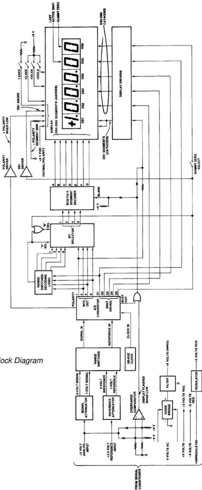
The purpose of this section is to explain how the Digital Indicator works by using a simplified block diagram. This section is not intended to provide a detailed explanation of electronic circuits for personnel untrained in electronic technology. However, it provides an adequate overview of operation for those familiar with basic electronic circuit operation. Throughout the following, refer to Figure 5.
Power Supplies. The integrated-circuit chips which comprise the A/D Converter and the Overrange Comparator are CMOS circuits which require ±9 volts regulated. These voltages are supplied from power supplies contained on the Signal Conditioner circuit board and are discussed in the Signal Conditioner Instruction Manual.
The digital part of the A/D Converter, the Bit Selector, and the various logic gates and inverters are operated from +5 volts regulated (TTL logic). The +5 volt supply consists of a three-terminal Regulator. The unregulated input to the Regulator is obtained from Signal Conditioner circuit board (unregulated side of +9 volt supply).
The BCD-to-7-Segment, Decoder, Display Drivers, and Display LED's operate from +6 volts unregulated. Five volts ac is supplied from the Signal Conditioner circuit board (secondary of power transformer located on board). Plus 6 volts unregulated is developed with a Diode Bridge and Filter located on the Digital Indicator board.
A +2.5 volts precision reference is supplied from a precision power supply located on the Signal Conditioner circuit board. This reference is used in the A/D Converter for digitizing the analog input signal.
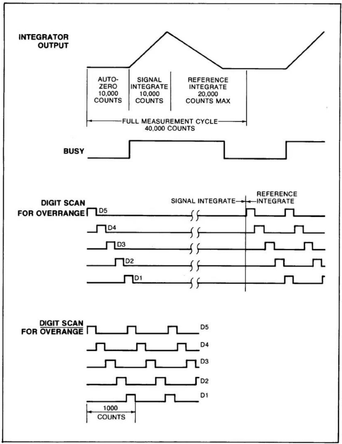
A/D Converter. The A/D Converter is a dual-slope converter which digitizes the analog input signal using a ratiometric integrating technique. The analog signal input, a reference input, and a clock input are applied to the converter. The measurement cycle is divided into an Auto-Zero cycle, a Signal Integrate cycle, and
a Reference Integrate cycle. Each cycle has a time base in which a certain amount of clock pulses occur. The clock used is a 100-kHz crystal oscillator. The Auto-Zero cycle is used to bring the output of the integrator to zero and lasts 10,000 counts. The next cycle is the Signal Integrate cycle which also lasts 10,000 counts. If the analog input is zero at the start of the Signal Integrate cycle, the integrator will see the same voltage that existed in the previous state. Thus, the integrator output will not change but will remain stationary during the entire Signal Integrate cycle. If the analog input is not equal to zero, an unbalanced condition exists compared to the Auto-Zero cycle and the integrator will generate a ramp whose slope is proportional to the analog input. At the end of this cycle, the sign of the ramp is determined. If the input signal was positive, a voltage which is VREF more negative than during Auto-Zero is applied to the integrator input. The A/D Converter chip generates the equivalent of a +Reference or -Reference from the single +Reference applied. The reference voltage returns the output of the integrator to zero. The time, or number of counts, required to do this is proportional to the input voltage. The Reference Integrate cycle can be a maximum of 20,000 counts. The full measurement cycle is then a maximum of 40,000 counts, with the answer to the measurement being achieved when the reference voltage returns the integrator output to zero. The full measurement cycle is shown in Figure 4.
The DIGIT DRIVES are positive-going signals that last for 200 clock pulses (see Figure 4). The scan sequence is D5 (MSD), D4, D3, D2, and D1 (last active digit). The scan is continuous unless an overrange occurs. Then all DIGIT DRIVES are blanked from the end of the first scan until the beginning of the Reference Integrate cycle when D5 will start the scan again. This gives a blinking or flashing display as a visual indication of overrange. Because the Digital Indicator has 5000 and 10000 ranges as well as a 20000 range, an analog Overrange Comparator is used as well as the inherent overrange capability of the A/D Converter. The Overrange Comparator is described in a following paragraph.
The binary-coded-decimal (BCD) outputs of the A/D Converter are positive logic signals that go on simultaneously with the DIGIT DRIVE. Since the DIGIT DRIVES are blanked for an overrange on the 20000 scale, the display will flash all zeros when this condition occurs on this scale.
Input Attenuators/Range Switches. The 5-volt analog signal input (full scale) and the 2.5 volt reference from the Signal Conditioner are applied to attenuator networks where 2-volt and 1-volt signal and reference inputs are developed for the A/D Converter. Since, on the 20000 range, the Reference Integrate cycle can be
"3000" Digital Indicator
other
| Signal Type | Count Range | | ----------------------- | ----------------- | | AUTO-ZERO | 10,000 | | SIGNAL INTEGRATE | 10,000 | | REFERENCE INTEGRATE | 20,000 | | COUNTS MAX | | | FULL MEASUREMENT CYCLE | 40,000 | | BUSY | | | DIGIT SCAN FOR OVERRANGE | D5 | | DIGIT SCAN FOR OVERRANGE | D4 | | DIGIT SCAN FOR OVERRANGE | D3 | | DIGIT SCAN FOR OVERRANGE | D2 | | DIGIT SCAN FOR OVERRANGE | D1 | | DIGIT SCAN FOR OVERRANGE | D5 | | DIGIT SCAN FOR OVERRANGE | D4 | | DIGIT SCAN FOR OVERRANGE | D3 | | DIGIT SCAN FOR OVERRANGE | D2 | | DIGIT SCAN FOR OVERRANGE | D1 | | 1000 COUNTS | |Figure 4. A/D Converter Timing Diagram
twice as long as the Signal Integrate cycle, the analog input voltage required to give a full-scale reading is exactly equal to 2 VREF. Consequently, on the 20000 range, the VREF is 1 volt and the VSIG is 2 volts for full scale. On the 10000 range, the two cycles can be equal; thus, VSIG = VREF = 2 volts. On the 5000 range, the analog voltage for a full-scale reading is then equal to 1/2 VREF; thus, VREF must be 2 volts and VSIG 1 volt. The appropriate levels are switched to the A/D Converter through the rear-panel Range switches.
Bit Selector/Decoding Logic. The Bit Selector transfers one of two sets of 4-line BCD data applied at input ports to output ports upon receiving a command at the A SELECT or B SELECT port. When the A SELECT port is high, the X input data is transferred to the Z output ports. Conversely, when the B SELECT input is high, the Y input data is transferred to the Z output ports. The Y data is obtained directly from the BCD output ports of the A/D Converter. The X data is comprised of specially coded bits used to count by 2's or 5's when the 10000 or 20000 ranges are selected, respectively. On the 5000 range, the A SELECT input is held low through the Range switches and the B SELECT input is high. The Y data is transferred to the output of the Bit Selector and the display count is by 1's. On the 10000 range, the A SELECT input is held low except when the D1 DIGIT DRIVE is high. When D1 is high, the A SELECT is high and the B SELECT is low, transferring the X data to the Z ports of the Bit Selector and allowing the display to count by 2's. Operation on the 20000 range is identical except that the bit coding is arranged to give a count by 5's with the X data.
Display Coding/Driving. The display is a 4.5-digit LED display with polarity and a dummy zero. DS2 through DS6 are 7-segment displays with common cathodes. The Bit Selector output ports are connected as inputs to a BCD-to-7-Segment Decoder. The 7 outputs of the decoder are connected as inputs to the segments (anodes) of DS2 through DS6. The DIGIT DRIVES of the A/D Converter are used to sequentially turn on DS2 through DS6 through Display Drivers which sink current. DS1 is either unlit or lights as a 1 for displays of 10000 or greater. Unlike DS2 through DS6, DS1 is a common anode device. The DS1 segments (cathodes) are sinked via a display driver from the 1 bit of the A/D Converter. The DS1 anode is then brought high by D5 through a driver comprised of an inverter and a transistor which applies +6 volts unregulated to the anode when D5 is high.
The last digit of the Display (DS6) is the dummy zero digit. When the Dummy Zero Select switch is ON, the DS6 cathode is sinked when D5 is high. The outputs of the BCD-to-7-Segment Decoder are tied to the DS6 segments. Also, when D5 is
"3000" Digital Indicator
high, the B SELECT input to the Bit Selector is pulled low through the NOR gate connected to the port. The A SELECT input is also low since it is either held hard low through the Range switches on the 5000 range or it is connected to D1 through the Range switches on the 10000 and 20000 ranges (when D5 is high D1 must be low). With the A SELECT and B SELECT inputs both low, the Z ports of the Bit Selector assume the low state no matter what the X and Y input data reads. Consequently, each time D5 is high, DS6 displays a zero.
The polarity sign is also part of DS1. The minus (-) segment is always lit through 6 volts and an external resistor tied to circuit common. When the A / D Converter senses a positive polarity, the POLARITY port goes high. This action drives an inverter low to light the vertical portion of the polarity sign.
Decimal point position is selected with rear-panel slide switches (as is dummy zero selection). Only one of the Decimal slide switches is turned ON at any one time. The decimal-point LED for DS1 is hard wired to +6 volts. Turning ON the associated Decimal switch connects an external resistor and circuit common to the other side of the decimal-point LED. Since the remaining digits with decimal-point LED's (DS2 through DS4) are common cathodes devices, each LED is sinked when the corresponding DIGIT DRIVE is high and associated Decimal switch is ON, applying +6 volts to the other side of the LED through an external resistor.
Analog Overrange. Digital overrange for the 20000 range is inherent in the A/D Converter chip and has been previously described. However, for the 5000 and 10000 ranges, an analog overrange circuit is required. The Overrange Comparator is dc biased with equal resistors returned to the ±9 volt supplies so that its output is at approximately 4.5 volts. Both of the comparator inputs are connected through diodes to the analog input from the Signal Conditioner. When the analog input is one diode drop above or below the comparator biasing, an overrange condition exists since approximately 5.2 volts is present at the analog input (5 volts = full-scale value). The output of the Overrange Comparator goes low when either of the input diodes is forward biased. The comparator output and the BUSY output of the A/D Converter are gated through an OR gate. The BUSY signal is high during the Signal and Reference Integrate cycles of the A/D Converter, then it goes low. This causes the output of the OR gate to go low. The BLANK port of the BCD-to-7-Segment Decoder is normally held high through an external resistor. When the OR gate output goes low, the BLANK port is pulled low through a diode, causing DS2 through DS6 to flash. Since DS1 is not driven from the decoder, a second diode and resistor are used to pull the A/D Converter 1-bit output low when the overrange OR gate is low. This action causes DS1 to flash.
Figure 5. Block Diagram
flowchart
graph TD
    A["Signal Attenuator"] -->|+2.5 VOLT REFERENCE INPUT| B["REFERENCE ATTENUATOR"]
    B -->|+2.5 VOLT REFERENCE INPUT| C["RANGE SWITCHES"]
    C -->|+2.5 VOLT REFERENCE INPUT| D["A/D CONVERTER DIGIT DRIVES"]
    D --> E["BCD TO-7-SEGMENT DECODER"]
    E --> F["DISPLAY DRIVERS"]
    F --> G["DS1 ANODE"]
    F --> H["DS2-DS6 SEGMENTS (ANODES)"]
    F --> I["DS3-DS4"]
    F --> J["DS5-DS6"]
    F --> K["DS1-DS2-DS3-DS4-DS5-DS6"]
    L["DIVISION RELATION"] --> M["DIODE BRIDGE"]
    M --> N["FILTER"]
    N --> O["+9 VOLTS UNREG"]
    P["OUTRANGE COMPARATOR"] --> Q["DISPLAY FLASHES WHEN LOW"]
    R["UNREGULATED"] --> S["+9 VOLTS REG"]
    T["REFERENCE"] --> U["1-VOLT REFERENCE"]
    V["0-VOLT"] --> W["-9 V"]
    X["+0 V"] --> Y["+2.5 VOLT REFERENCE INPUT"]
    Z["±5 VOLT ANALOG INPUT"] --> AA["SIGNAL ATTENUATOR"]
    AB["+2.5 VOLT REFERENCE INPUT"] --> AC["REFERENCE ATTENUATOR"]
    AD["100-KHZ CLOCK"] --> AE["CLOCK IN"]
    AF["DUMMY ZERO SELECT"] --> AG["DUMMY ZERO SELECT"]
    AH["Polarity"] --> AI["BIT SELECTOR"]
    AJ["SET"] --> AK["Bit Selector"]
    AL["ACK"] --> AM["Clock In"]
    AN["Polarity"] --> AO["Bit Selector"]
    AP["SET"] --> AQ["Bit Selector"]
    AR["Polarity"] --> AS["Bit Selector"]
    AT["Polarity"] --> AU["Bit Selector"]
    AV["Polarity"] --> AW["Bit Selector"]
    AX["Polarity"] --> AY["Bit Selector"]
    AZ["Polarity"] --> BA["Bit Selector"]
    BB["Polarity"] --> BC["Bit Selector"]
    BD["Polarity"] --> BE["Bit Selector"]
    BF["Polarity"] --> BG["Bit Selector"]
    BH["Polarity"] --> BI["Bit Selector"]
    BJ["Polarity"] --> BK["Bit Selector"]
    BL["Polarity"] --> BLA["Bit Selector"]
    BN["Polarity"] --> BO["Bit Selector"]
    BP["Polarity"] --> BPB["Bit Selector"]
    BPQ["Polarity"] --> BPQB["Bit Selector"]
    BPQP["Polarity"] --> BPQPQ["Bit Selector"]
    BPQPQ --> BPQPQQ["Bit Selector"]
    BPQPQQ --> BPQPQQQ["Bit Selector"]
    BPQPQQQ --> BPQPQQQ["Bit Selector"]
    BPQPQQQ --> BPQZPQ
    BPQZPQQ --> BPQZPQ
    BPQZPQQ --> BPQZPQ
5. VERIFICATION OF NORMAL OPERATION
It is the purpose of this section to aid the user in rapidly determining whether the Digital Indicator is functioning normally or whether it is the source of the observed trouble. In the event a repair to the Digital Indicator is required, a complete parts list, schematic diagram, and component location drawing are included in this manual. The user may also contact the factory Service Department or the local Daytronic Representative for assistance.
One of the two techniques can be used to rapidly determine whether the Digital Indicator is malfunctioning or whether the problem is in the Signal Conditioner, transducer, or transducer cabling. If the unit is a Form 2 instrument (no Hi-Lo Limits), attempt to zero and calibrate the Signal Conditioner while observing the Signal Conditioner analog output (use the dc-to-2Hz output) on a dc coupled oscilloscope. If the Digital Indicator is unstable or reads erratically, but the oscilloscope indicates a stable analog output from the Signal Conditioner, the problem is likely in the Digital Indicator. In the event the Signal Conditioner output is unstable or noisy, consult the Signal Conditioner Instruction Manual for the proper action to be taken.
If the instrument is a Form 3 type, push one of the Limit pushbuttons and observe how the limit value is displayed on the Digital Indicator. If the display is stable with the Limit button pressed, but is unstable when the button is released, the problem is in the Signal Conditioner, transducer, or transducer cabling. If the display is unstable or erratic whether the button is pressed or released, the problem is in the Digital Indicator.
MODEL
3300
HI-LO LIMITS
INSTRUCTION MANUAL

text_image
-187135 -18235 +1915 +2.145 +1935 -18265 -18430 -99253000
Instrument Series
MODEL
3300
HI-LO LIMITS
INSTRUCTION MANUAL
PLEASE NOTE:
Units manufactured after Y2001 (as noted by serial number starting with the letter W, then X, Y .....). The "Output Disable" feature on the Limit Output connector was eliminated.
TABLE OF CONTENTS
Section Page
1 Description 1
2 Installation 3
3 Operation 8
4 Block Diagram Description 12
5 Verification of Normal Operation 14
LIST OF ILLUSTRATIONS
Figure Page
1 3000 Series Instruments with Hi-Lo Limits .... 1
2 Limit Modes 5
3 Fast/Slow Signal Solder-Drop Terminals 7
4 Model 9399 Triac Controller Wiring 9
5 External Relay Driver Wiring 10
6 Front-Panel Description 11
7 Block Diagram 15
LIST OF TABLES
Table Page
1 3000 Series Model Numbering 2
2 Specifications 4
3 Limit Output Connector Functions/Pin Nos. 8
PLEASE NOTE: Sections 6 and 7, Figures 8 and 9, and Table 4 have been removed from this manual.
If you need information regarding specific 3330 components and circuitry, please contact the Daytronic Service Department at (937) 293-2566.
NOTE
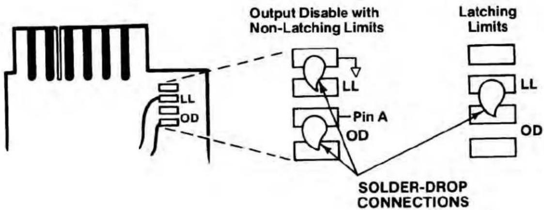
The Model 3300 may operate in either of two modes: Latching Limits (LL), where limit logic outputs are held until application of an external Reset action, or Output Disable (OD), where limit logic outputs are non-latching being automatically disabled as soon as the Violation condition ceases.
Unless you have specified otherwise, your Model 3300 will have been preset at the factory for non-latching operation, through solder-drop terminals on the underside (“Side 1”) of the printed-circuit board, as shown below. You may at any time, however, resolder the terminal connections as shown to produce latching limit outputs.
flowchart
graph TD
    A["Input Block"] --> B["Output Disable with Non-Latching Limits"]
    B --> C["LL Pin A"]
    B --> D["LL Pin A"]
    B --> E["Pin A"]
    B --> F["Latching Limits"]
    C --> G["SOLDER-DROP CONNECTIONS"]
    D --> G
    E --> G
    F --> G
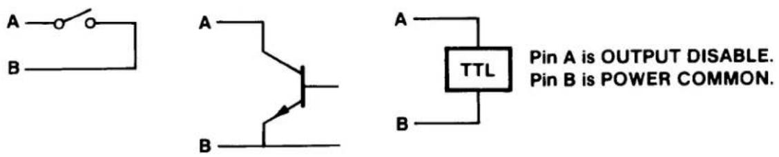
For latching operation, you must also provide an external means of resetting the limit outputs as soon as the condition(s) giving rise to the violation have ceased to exist, thus resetting the 3300 to continue normal limit monitoring. To reset latched limit outputs, Pins A and B of the Limit Output Connector (see Table 3, p. 8) must be connected by one of the three methods shown below:
text_image
A B A B A TTL Pin A is OUTPUT DISABLE. Pin B is POWER COMMON.In all discussions of limit logic outputs in this manual, “normal”—i.e., Output Disable—operation of the Model 3300 is presumed.
INSTRUCTION MANUAL 3300 SERIES HI-LO LIMITS
1. DESCRIPTION
The 3000 Instrument Series is a family of premium signal conditioning instruments that includes models to accommodate virtually all types of transducers and signal sources commonly encountered in electro-mechanical testing and control operations. The 3000 Instruments are available in three forms: Form 1 contains the Signal Conditioner only; Form 2 is the Signal Conditioner with Digital Indicator; Form 3 is the Signal Conditioner with Digital Indicator and Hi-Lo Limits. The model numbering system used with the 3000 Series identifies the form and the type of signal source. This numbering system is further explained in Table 1. From Table 1, it can be seen that all models having Hi-Lo Limits are identified by a 33XX number, with the last two digits identifying the type of signal source (thermocouple, LVDT, etc).

text_image
+4997 psi CONSTAIN GAGE INDICATOR/CONTROLLER LOW OK HIGH Set Low Limit Set High Limit DAYTRONIC Model 3378Figure 1. 3000 Series Instrument with Hi-Lo Limits
Table 1. 3000 Series Model Numbering
text_image
"3" is series identifier, used with all units: Second digit identifies "form": "1" = signal conditioner only "2" = signal conditioner with digital indicator "3" = signal conditioner with digital indicator and Hi-Lo limits Third and fourth digits identify type of signal source: "10" = Type J Thermocouple "11" = Type K Thermocouple "15" = Thermistors "30" = LVDT's "40" = Pulse Pick-up's (Frequency) "63" = DC Volts/Millivolts/ DC-DC LVDT's/Potentiometers "70" = Strain Gages (DC excited) "78" = Strain Gages (AC excited) Etc. Model 3 X X XThe 3000 Series instruction manual system is designed to provide the user with the following documentation: (1) a separate instruction manual for each type of Signal Conditioner purchased; (2) an instruction manual covering only the Digital Indicator section of a 3000 Series instrument, but applicable to any Form 3 instrument. It is the purpose of this manual to cover the Hi-Lo Limit section of all Form 3 instruments.
Daytronic Corporation
The Hi-Lo Limit section of any Form 3 instrument consists of the following: (1) an additional printed-circuit board on which are mounted the required circuit components for Hi-Lo Limit operation, (2) associated front-panel controls and indicators, and (3) a rear-panel connector where the Limit mode is selected and where Limit logic outputs can be obtained.
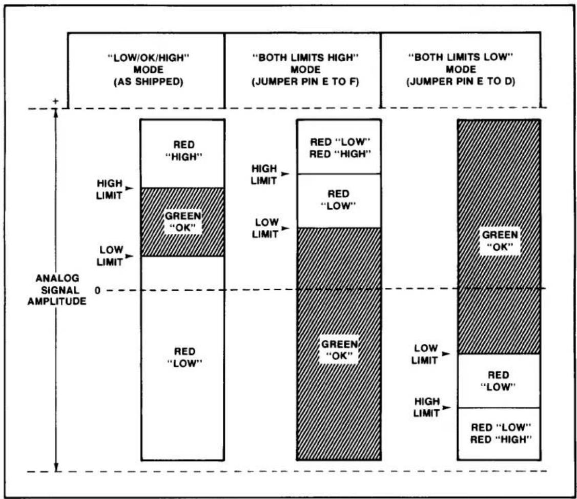
The 3300 Series instruments can be used in any of three Limit modes. The Low/OK/High is the most common mode of operation and is used to detect when the analog signal drops below a Low limit or exceeds a High limit. The range in between limits is designated as OK. The second mode which can be used is the Both Limits High mode where both limits are above the OK range. The third mode is the opposite function, or the Both Limits Low mode, where both limits are below the OK range. In all three modes of operation, the limits can be set across the entire ± signal range (±5 volts). The instrument is shipped for operation in the Low/OK/High mode, but either of the other two modes can be easily selected by wiring of the rear-panel Limit output connector (see Section 2, Installation).
Both true and complement limit logic outputs are available at the Limit output connector for the Low/OK/High functions. The outputs are wire-ORable, TTL compatible (10 milliamperes sink, 0.5 milliamperes source). For latching limits, see NOTE, inside front cover.
Front-panel status indicators light to indicate when a limit is exceeded or when the analog signal is within the OK range. A red LED is used for each of the limits and a green LED is used as the OK indicator.
Coarse and Fine setting potentiometers are provided for each limit. Individual Push-to-Set buttons cause the limit value to be displayed by the Digital Indicator in the proper engineering units. A typical 3300 Instrument is shown in Figure 1. The specifications for the Limit section are given in Table 2.
2. INSTALLATION
The 3000 Series Instruments can be operated as bench-top instruments or they can be rack- or panel-mounted. Dimensions for all three types of mounting and corresponding mounting instructions are given in the accompanying Signal Conditioner Instruction Manual. The following paragraphs provide instructions for limit mode selection, input filtering, logic output connections, and ac power connection.
Table 2. Specifications
| Limit Status Display: Individual red LED's indicate if limits are violated. Single green LED indicates no violations (analog signal within OK range). |
| Limit Setting: Coarse and Fine setting potentiometers provided for each limit. Individual Push-to-Set buttons also provided. When button is pushed, limit is displayed in proper engineering units on Digital Indicator. |
| Limit Logic Outputs: Both true and complement outputs provide for Low/OK/High functions. Outputs are TTL compatible, wire Orable; 10 ma sink, 0.5 ma source (max). Logic outputs are normally disabled when violation ceases to occur, but latching mode is also available (see NOTE, inside front cover). |
| Limit Modes: Three modes are available thru rear-panel Limit output connector wiring. Units shipped with Low/OK/High mode activated. Both Limits High or Both Limits Low mode can be user selected. |
| Output Disable: An Output Disable line provided which, if tied low, will cause all limit logic outputs to go high (both true and complement for each function). |
Limit Mode Selection. Figure 2 illustrates the three modes in which 3300 Instruments can be operated. The unit is shipped from the factory with the Low/OK/High mode activated. In this mode, the Low limit is set some increment below the High limit. The increment between limits is the OK range. Either limit can be set positive or negative, as long as the Low limit is more negative than the High limit. When the High limit is exceeded, the front-panel LED status indicator (red) marked HIGH will light. When the analog signal drops below the Low limit, the front-panel LED status indicator (red) marked LOW will light. When the signal is between the two limits, the front-panel status indicator (green) marked OK will light. In this mode, only one of the three status indicators will light at any one time.
flowchart
graph TD
    A[""LOW/OK/HIGH" MODE (AS SHIPPED)"] --> B["RED "HIGH""]
    B --> C["GREEN "OK""]
    C --> D["RED "LOW""]
    D --> E["RED "LOW" RED "HIGH""]
    E --> F["RED "LOW" RED "LOW""]
    F --> G["GREEN "OK""]
    G --> H["RED "LOW" RED "HIGH""]
    H --> I["RED "LOW" RED "LOW""]
    I --> J["GREEN "OK""]
    J --> K["RED "LOW" RED "LOW""]
    K --> L["RED "LOW" RED "LOW""]
    style A fill:#f9f,stroke:#333
    style B fill:#ccf,stroke:#333
    style C fill:#cfc,stroke:#333
    style D fill:#fcc,stroke:#333
    style E fill:#cff,stroke:#333
    style F fill:#ffc,stroke:#333
    style G fill:#fcf,stroke:#333
    style H fill:#cff,stroke:#333
    style I fill:#ffc,stroke:#333
    style J fill:#cff,stroke:#333
    style K fill:#ffc,stroke:#333
    style L fill:#ffc,stroke:#333
Figure 2. Limit Modes
To activate the Both Limits High mode, jumper pin E to pin F at the supplied rear-panel Limit output connector. In this mode, the limits can also be set positive or negative, as long as the High limit is set some increment more positive than the Low limit. When the analog signal is below or more negative than the Low limit, the green OK indicator will light. When the Low limit is exceeded, the red LOW indicator will light (green OK will extinguish). When the High limit is exceeded, the red HIGH indicator will light and the red LOW indicator will remain lit to indicate that now both limits are exceeded. When the signal drops below the High limit (but not the Low limit), the LOW indicator will remain lit. When the signal drops below the Low limit, the LOW indicator will extinguish and the OK indicator will again light to indicate no violations.
"3000" Hi-Lo Limits
To activate the Both Limits Low mode, jumper pin E to pin D at the Limit output connector. In this mode, the limits can also be set positive or negative, as long as the High limit is set some increment more negative than the Low limit. This mode works exactly opposite to that described in the preceding paragraph. When the analog signal is above or more positive than the Low limit, the green OK indicator will light. When the signal drops below the Low limit, the red LOW indicator will light (green OK will extinguish). When the signal drops below the High limit, the red HIGH indicator will light and the red LOW indicator will remain lit to indicate that now both limits are violated. When the signal rises above the High limit (but not the Low limit), only the LOW indicator will remain lit. When the signal rises above the Low limit, the LOW indicator will extinguish and the OK indicator will again light to indicate no violations.
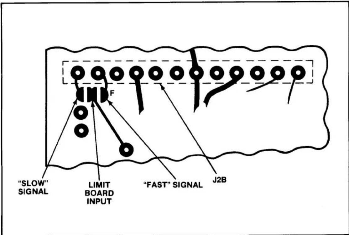
Input Filtering. Two filtered outputs are brought from the Signal Conditioner printed-circuit board to the Limit printed-circuit board. Both are low-pass filter outputs with one having a cutoff frequency of 200 Hz (fast signal) and the other having a cutoff frequency of 2 Hz (slow signal). The fast signal is normally connected to the Limit board circuitry via a solder-drop terminal labelled F on the underside (Side 1) of the Limit board (all 3300 units are shipped with this connection made). Instrument operation should be attempted without removing this connection. However, if excessive limit chattering is encountered (transducer is subject to excessive vibration etc.), this convection should be removed and the slow signal terminals should be connected via a solder drop. The fast and slow signal solder-drop terminals are illustrated in Figure 3.
Logic Output Connections. Logic outputs are provided at the Limit output connector for the Low/OK/High functions. Both true and complement outputs are provided that are TTL compatible (10 millamperes sink, 0.5 millamperes source maximum). These outputs may be used to trigger alarms or sort/reject devices etc. Typical wiring to these outputs to obtain a contact closure is shown in Figures 4 and 5. In Figure 4, wiring to a Daytronic 9399 Triac Controller is illustrated. Notice that while a variety of logic configurations can cause a contact closure, that current is always sinked by the 3300 instrument. If a device other than the 9399 is used, a resistor must be placed in series with the +5 volt line from the 3300 to limit the sink current to 10 milliamperes maximum.
Figure 5 shows the wiring and external circuitry when it is desired to close an external relay contact using source current. Only a Q output is used in this configuration and the source current drawn must be limited to 0.5 milliamperes maximum.
flowchart
graph TD
    A[""SLOW" SIGNAL"] --> B["Barrier F"]
    C["LIMIT BOARD INPUT"] --> B
    D[""FAST" SIGNAL"] --> B
    B --> E["J2B"]
Figure 3. Fast/Slow Signal Solder-Drop Terminals
An Output Disable is also provided at the Limit output connector (pin A). When pin A is jumpered to pin B (common), all logic outputs (true and complement) are held high (+5 volts). Table 3 gives a listing of the functions available at the Limit output connector and the corresponding pin numbers.
AC Power Connection. To protect operating personnel, the 3000 Series Instruments are equipped with a three-conductor power cord. When the cord is plugged into the appropriate receptacle, the instrument is grounded. The offset pin on the power cord is ground. To maintain the safety ground when operating the instrument from a two-contact outlet, use a three-prong to two-prong adaptor and connect the green pigtail on the adaptor to ground.
To prepare the instrument for operation, connect the power cable to a 105-135 volt ac, 50-400 Hz power source. The instrument can use up to 5 watts of power.
Table 3. Limit Output Connector Functions/Pin Nos.
| Function | Pin Number |
| +5 volts | C |
| Common | B |
| Limit Select | E |
| Both Lo | D |
| Both Hi | F |
| Output Disable | A * |
| Q_Lo | 5 |
| _Lo | 6 |
| Q_Hi | 1 |
| _Hi | 2 |
| Q_OK | 3 |
| _OK | 4 |
| * Note feature disable on units built after Y2001 |
Note: Jumper E to F to enable Both Limits High mode. Jumper E to D to enable Both Limits Low mode. No connection to E enables Low/OK/High mode.
3. OPERATION
The only operation required is turning ON/OFF ac power and setting the desired limits. These operations are described in the following paragraphs. Figure 6 provides a functional description of the front-panel.
Power On/Off. AC power is turned ON/OFF the instrument by means of a rear-panel slide switch. The digital display lights immediately when ac power is ON.
text_image
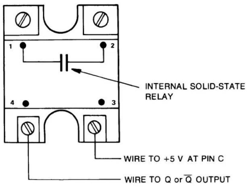
INTERNAL SOLID-STATE RELAY WIRE TO +5 V AT PIN C WIRE TO Q or Q̅ OUTPUT- Wire pin 4 of 9399 to Hi or Lo output for contact closure at violation of limit.
- Wire pin 4 of 9399 to QHi or QLo output for contact closure with no violation.
- Wire pin 4 of 9399 to _OK output for contact closure with no violation.
- Wire pin 4 of 9399 to QOK output for contact closure at violation.
- If Triac Controller other than 9399 is used, make certain sink current does not exceed 10 ma for TTL outputs.
Figure 4. Model 9399 Triac Controller Wiring
text_image
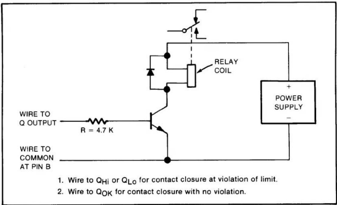
WIRE TO Q OUTPUT R = 4.7 K WIRE TO COMMON AT PIN B RELAY COIL POWER SUPPLY - 1. Wire to QHi or QLo for contact closure at violation of limit. 2. Wire to QOK for contact closure with no violation.Figure 5. External Relay Driver Wiring
Limit Setting. Before setting the Low and High limits, the user should refer to Section 2 of this manual and become familiar with the limit mode in which the instrument is to be operated. Figure 2 illustrates the three operating modes by giving a graphic representation of typical limit settings. The Limit logic outputs wiring should also be reviewed before attempting to operate the instrument. This information is also contained in Section 2. To prevent inadvertent triggering of external circuits while setting the limits, remove the rear-panel Limit output connector. The connector can then be replaced after the proper limits have been set. To set the limits, proceed as follows:
(a) Press the Set Low Limit button and adjust the Coarse and Fine Low limit controls until the desired Low limit value is displayed on the Digital Indicator.
(b) Press the Set High Limit button and adjust the Coarse and Fine High limit controls until the desired High limit value is displayed on the Digital Indicator.
Daytronic Corporation
(c) The limits are now set and the appropriate LOW and HIGH status indicators will light when a violation of the limit occurs. The OK indicator will be lit when there is no violation. NOTE: For the front-panel status indicators to have meaning as marked, the Low limit must be set more negative than the High limit in the Low/OK/High and Both Limits High modes. In the Both Limits Low mode, the Low limit must be set more positive than the High limit for the terminology to have meaning.
text_image
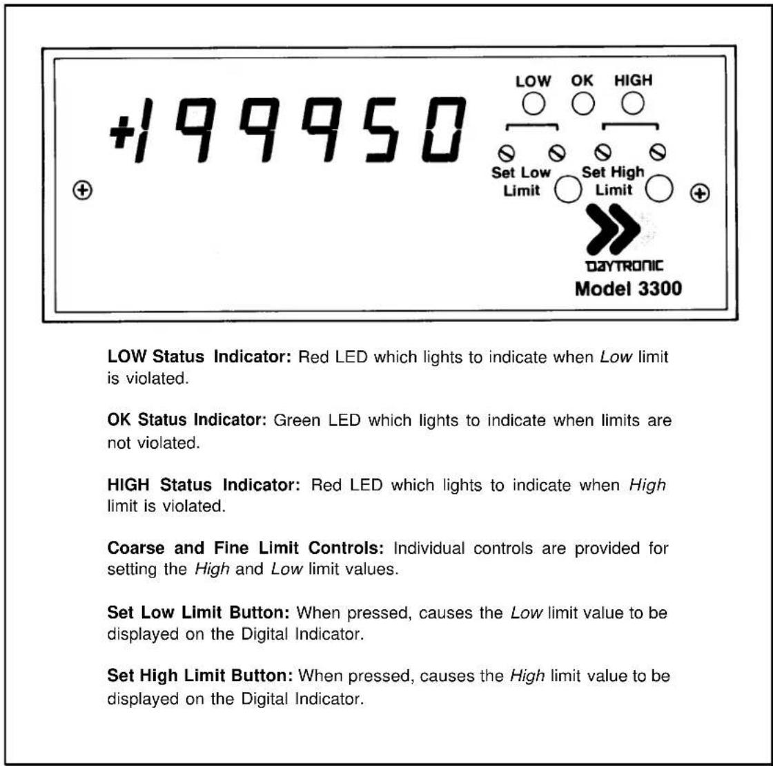
+199950 LOW OK HIGH Set Low Set High Limit Limit DAYTRONIC Model 3300 LOW Status Indicator: Red LED which lights to indicate when Low limit is violated. OK Status Indicator: Green LED which lights to indicate when limits are not violated. HIGH Status Indicator: Red LED which lights to indicate when High limit is violated. Coarse and Fine Limit Controls: Individual controls are provided for setting the High and Low limit values. Set Low Limit Button: When pressed, causes the Low limit value to be displayed on the Digital Indicator. Set High Limit Button: When pressed, causes the High limit value to be displayed on the Digital Indicator.Figure 6. Front-Panel Description
4. BLOCK DIAGRAM DESCRIPTION
The purpose of this section is to explain how the Limit circuits work by using a simplified block diagram. This section is not intended to provide a detailed explanation of electronic circuits for personnel untrained in electronic technology. However, it provides an adequate overview of operation for those familiar with basic electronic circuit operation. Throughout the following, refer to Figure 7.
A +2.5 volt precision Reference is supplied from a precision power supply located on the Signal Conditioner circuit board. This Reference is supplied as an input to a non-inverting amplifier from which the voltages are developed which are used for limit setting. A +5.6 volt level is obtained at the output of the Reference Amplifier and a -5.6 volt level is generated through the use of a Unity Gain Inverter. The ±5.6 volt levels are then applied across the Fine and Coarse limit potentiometers. The potentiometer wipers are summed together, then applied as non-inverting inputs to Buffer Amplifiers (one for the Low Limit channel and one for the High Limit Channel). Each Buffer Amplifier output is wired to a normally-open contact of a Set Limit pushbutton. When either pushbutton (Set Low Limit or Set High Limit) is pressed, the limit value is connected as an input to the Digital Indicator (analog output from the Signal Conditioner is disconnected from the Digital Indicator input). While the limit value is displayed on the Digital Indicator, the appropriate value can be set with the Fine and Coarse limit potentiometers. The Buffer Amplifier outputs are applied as inputs to a pair of voltage Comparators. The analog output from the Signal Conditioner is applied to each of the remaining Comparator inputs. When the signal is less than the limit set point, a Comparator output will be at a logic 1 level (+9 volts). When the signal is greater than the limit set point, a Comparator output will be at a logic 0 level (-9 volts).
Filtered outputs from the Signal Conditioner are applied to the Limit printed-circuit board. Both dc-to-200 Hz and dc-to-2 Hz analog outputs are provided. The 200-Hz signal is referred to as the fast signal and is normally connected to the limit circuits via a solder-drop connection. The 2-Hz signal, or slow signal, can be connected as an input to the limit circuits by unsoldering the fast signal solder terminal and soldering the slow terminal to the limit circuit input terminal. This is usually accomplished if limit chattering is encountered during operation. The fast signal is always connected to the limit input at factory fabrication.
Limit mode selection is accomplished by connecting the Both Limits High line or the Both Limits Low line to the Limit Select line (-9 volts) at the Limit output connector. The unit is shipped with neither of these connections made, automatically enabling the Low/OK/High mode. Exclusive OR logic is used to detect a violation. Two exclusive OR gates are used with a 60-Hz Filter inserted between gates (diode-capacitor peak detector) to eliminate any ripple which might cause false triggering of the logic.
The first gate in the Low Limit channel has an input held low (thru an inverter whose input is tied high with a pull-up resistor) when the Low/OK/High mode is operational. When the analog signal is less than the set point, the remaining input to the gate is high. The gate output is consequently high. The second gate has one input tied low, thus its output is also high when the signal is less than the set point. Since this is the condition for a violation of the Low limit in the Low/OK/High mode, the LOW lamp (red LED) is lit through an inverter.
The first gate in the High Limit channel has an input held high (thru a pull-up resistor) when the Low/OK/High mode is operational.. When the analog signal is greater than the set point, the remaining input to the gate is low. The gate output is consequently high. The second gate has one input tied low, thus its output is also high when the signal is greater than the set point. Since this is the condition for a violation of the High limit in the Low/OK/High mode, the HIGH lamp (red LED) is lit through an inverter.
The gated outputs of the Low and High Limit channels are ORed together to light the OK lamp (green LED). Both outputs must be low (no violation) to take the OR gate output high. With this output high, the OK lamp is lit through an inverter.
When the Both Limits High line is tied to the Limit Select line (-9 volts), the input to the first gate in the Low Limit channel is held high through the inverter. This reverses the logic and causes the Low Limit channel to be violated by an increasing analog signal. Operation of the High Limit channel remains as before, and the OK lamp lights when the signal is below both of the set points.
When the Both Limits Low line is tied to the Limit Select line, the input to the first gate in the High Limit channel is held low. This reverses the logic and causes
"3000" Hi-Lo Limits
the High Limit channel to be violated by a decreasing signal. Operation of the Low Limit channel remains as in the Low/OK/High mode, and the OK lamp lights when the signal is above both of the set points.
Both true and complement outputs are provided for the Low/OK/High functions. These outputs are provided via a hex inverter chip with open-collector outputs. The open collectors are tied to +5 volts via pull-up resistors to provide TTL compatible outputs. An Output Disable line is provided which takes all outputs to +5 volts when tied to circuit common. This removes the +9 volts operating voltage from the hex inverter chip so that the outputs go to the pull-up resistor voltage of +5 volts. (This feature is disabled on units built after 2001)
The ±9 Volts Regulated is supplied from power supplies contained on the Signal Conditioner circuit board. The +5 Volts Regulated is developed by a three-terminal Regulator. The Unregulated input to the Regulator is obtained from the Signal Conditioner circuit board (unregulated side of +9 volt supply). The +9 volt supplies are discussed in the Signal Conditioner Instruction Manual.
5. VERIFICATION OF NORMAL OPERATION
It is the purpose of this section to aid the user in rapidly determining whether the limit circuits are functioning normally or whether they are the source of the observed trouble. In the event a repair to the limit circuits is required, a complete parts list, schematic diagram, and component location drawing are included in this manual. The user may also contact the factory Service Department or the local Daytronic Representative for assistance.
(a) Make certain that the desired limit mode has been properly selected and that the limits have been set according to the front-panel terminology. The Low limit should be set more negative than the High limit in the Low/OK/High and Both Limits High modes. The Low Limit should be set more positive than the High limit when the Both Limits Low mode is used.
(b) Make certain that some input is provided to the Signal Conditioner so that the Digital Indicator is reading a value off zero in the direction of the Low limit.

flowchart
graph TD
    A["OUTR OUTPUT OISABLE"] --> B["Low"]
    B --> C["High"]
    C --> D["CONTROL INPUT"]
    D --> E["CONTROL INPUT"]
    E --> F["CONTROL INPUT"]
    F --> G["CONTROL INPUT"]
    G --> H["CONTROL INPUT"]
    H --> I["CONTROL INPUT"]
    I --> J["CONTROL INPUT"]
    J --> K["CONTROL INPUT"]
    K --> L["CONTROL INPUT"]
    L --> M["CONTROL INPUT"]
    M --> N["CONTROL INPUT"]
    N --> O["CONTROL INPUT"]
    O --> P["CONTROL INPUT"]
    P --> Q["CONTROL INPUT"]
    Q --> R["CONTROL INPUT"]
    R --> S["CONTROL INPUT"]
    S --> T["CONTROL INPUT"]
    T --> U["CONTROL INPUT"]
    U --> V["CONTROL INPUT"]
    V --> W["CONTROL INPUT"]
    W --> X["CONTROL INPUT"]
    X --> Y["CONTROL INPUT"]
    Y --> Z["CONTROL INPUT"]
    Z --> AA["CONTROL INPUT"]
    AA --> AB["CONTROL INPUT"]
    AB --> AC["CONTROL INPUT"]
    AC --> AD["CONTROL INPUT"]
    AD --> AE["CONTROL INPUT"]
    AE --> AF["CONTROL INPUT"]
    AF --> AG["CONTROL INPUT"]
    AG --> AH["CONTROL INPUT"]
    AH --> AI["CONTROL INPUT"]
    AI --> AJ["CONTROL INPUT"]
    AJ --> AK["CONTROL INPUT"]
    AK --> AL["CONTROL INPUT"]
    AL --> AM["CONTROL INPUT"]
    AM --> AN["CONTROL INPUT"]
    AN --> AO["CONTROL INPUT"]
    AO --> AP["CONTROL INPUT"]
    AP --> AQ["CONTROL INPUT"]
    AQ --> AR["CONTROL INPUT"]
    AR --> AS["CONTROL INPUT"]
    AS --> AT["CONTROL INPUT"]
    AT --> AU["CONTROL INPUT"]
    AU --> AV["CONTROL INPUT"]
    AV --> AW["CONTROL INPUT"]
    AW --> AX["CONTROL INPUT"]
    AX --> AY["CONTROL INPUT"]
    AY --> AZ["CONTROL INPUT"]
    AZ --> BA["CONTROL INPUT"]
    BA --> BB["CONTROL INPUT"]
    BB --> BC["CONTROL INPUT"]
    BC --> BD["CONTROL INPUT"]
    BD --> BE["CONTROL INPUT"]
    BE --> BF["CONTROL INPUT"]
    BF --> BG["CONTROL INPUT"]
    BG --> BH["CONTROL INPUT"]
    BH --> BI["CONTROL INPUT"]
    BI --> BJ["CONTROL INPUT"]
    BJ --> BK["CONTROL INPUT"]
    BK --> BL["CONTROL INPUT"]
    BL --> BM["CONTROL INPUT"]
    BM --> BN["CONTROL INPUT"]
    BN --> BO["CONTROL INPUT"]
    BO --> BP["CONTROL INPUT"]
    BP --> BQ["CONTROL INPUT"]
    BQ --> BR["CONTROL INPUT"]
    BR --> BS["CONTROL INPUT"]
    BS --> BT["CONTROL INPUT"]
    BT --> BU["CONTROL INPUT"]
    BU --> BV["CONTROL INPUT"]
    BV --> BW["CONTROL INPUT"]
    BW --> BX["CONTROL INPUT"]
    BX --> BY["CONTROL INPUT"]
    BY --> BZ["...VOUT LIMIT CHANNEL"]
    BZ --> CA["VOUT LIMIT CHANNEL LOW..."]

    subgraph Inputs
        D1["HIGH LIMIT CHANNEL"]
        D2["LOW LIMIT CHANNEL"]
        D3["LOW LIMIT CHANNEL"]
        D4["LOW LIMIT CHANNEL"]
        D5["LOW LIMIT CHANNEL"]
        D6["LOW LIMIT CHANNEL"]
        D7["LOW LIMIT CHANNEL"]
        D8["LOW LIMIT CHANNEL"]
        D9["LOW LIMIT CHANNEL"]
        D10["LOW LIMIT CHANNEL"]
        D11["LOW LIMIT CHANNEL"]
        D12["LOW LIMIT CHANNEL"]
        D13["LOW LIMIT CHANNEL"]
        D14["LOW LIMIT CHANNEL"]
        D15["LOW LIMIT CHANNEL"]
        D16["LOW LIMIT CHANNEL"]
        D17["LOW LIMIT CHANNEL"]
        D18["LOW LIMIT CHANNEL"]
        D19["LOW LIMIT CHANNEL"]
        D20["LOW LIMIT CHANNEL"]
        D21["LOW LIMIT CHANNEL"]
        D22["LOW LIMIT CHANNEL"]
        D23["LOW LIMIT CHANNEL"]
        D24["LOW LIMIT CHANNEL"]
        D25["LOW LIMIT CHANNEL"]
        D26["LOW LIMIT CHANNEL"]
        D27["LOW LIMIT CHANNEL"]
        D28["LOW LIMIT CHANNEL"]
        D29["LOW LIMIT CHANNEL"]
        D30["LOW LIMIT CHANNEL"]
        D31["LOW LIMIT CHANNEL"]
        D32["LOW LIMIT CHANNEL"]
        D33["LOW LIMIT CHANNEL"]
        D34["LOW LIMIT CHANNEL"]
        D35["LOW LIMIT CHANNEL"]
        D36["LOW LIMIT CHANNEL"]
        D37["LOW LIMIT CHANNEL"]
        D38["LOW LIMIT CHANNEL"]
        D39["LOW LIMIT CHANNEL"]
        D40["LOW LIMIT CHANNEL"]
        D41["LOW LIMIT CHANNEL"]
        D42["LOW LIMIT CHANNEL"]
        D43["LOW LIMIT CHANNEL"]
        D44["LOW LIMIT CHANNEL"]
        D45["LOW LIMIT CHANNEL"]
        D46["LOW LIMIT CHANNEL"]
        D47["LOW LIMIT CHANNEL"]
        D48["LOW LIMIT CHANNEL"]
        D49["LOW LIMIT CHANNEL"]
        D50["LOW LIMIT CHANNEL"]
        D51["LOW LIMIT CHANNEL"]
        D52["LOW LIMIT CHANNEL"]
        D53["LOW LIMIT CHANNEL"]
        D54["LOW LIMIT CHANNEL"]
        D55["LOW LIMIT CHANNEL"]
        D56["LOW LIMIT CHANNEL"]
        D57["LOW LIMIT CHANNEL"]
        D58["LOW LIMIT CHANNEL"]
        D59["LOW LIMIT CHANNEL"]
        D60["LOW LIMIT CHANNEL"]
        D61["LOW LIMIT CHANNEL"]
        D62["LOW LIMIT CHANNEL"]
        D63["LOW LIMIT CHANNEL"]
        D64["LOW LIMIT CHANNEL"]
        D65["LOW LIMIT CHANNEL"]
        D66["LOW LIMIT CHANNEL"]
        D67["LOW LIMIT CHANNEL"]
        D68["LOW LIMIT CHANNEL"]
        D69["LOW LIMIT CHANNEL"]
        D70["LOW LIMIT CHANNEL"]
        D71["LOW LIMIT CHANNEL"]
        D72["LOW LIMIT CHANNEL"]
        D73["LOW LIMIT CHANNEL"]
        D74["LOW LIMIT CHANNEL"]
        D75["LOW LIMIT CHANNEL"]
        D76["LOW LIMIT CHANNEL"]
        D77["LOW LIMIT CHANNEL"]
        D78["LOW LIMIT CHANNEL"]
        D79["LOW LIMIT CHANNEL"]
        D80["LOW LIMIT CHANNEL"]
        D81["LOW LIMIT CHANNEL"]
        D82["LOW LIMIT CHANNEL"]
        D83["LOW LIMIT CHANNEL"]
        D84["LOW LIMIT CHANNEL"]
        D85["LOW LIMIT CHANNEL"]
        D86["LOW LIMIT CHANNEL"]
        D87["LOW LIMIT CHANNEL"]
        D88["LOW LIMIT CHANNEL"]
        D89["LOW LIMIT CHANNEL"]
        D90["LOW LIMIT CHANNEL"]
        D91["LOW LIMIT CHANNEL"]
        D92["LOW LIMIT CHANNEL"]
        D93["LOW LIMIT CHANNEL"]
        D94["LOW LIMIT CHANNEL"]
        D95["LOW LIMIT CHANNEL"]
        D96["LOW LIMIT CHANNEL"]
        D97["LOW LIMIT CHANNEL"]
        D98["LOW LIMIT CHANNEL"]
        D99["LOW LIMIT CHANNEL"]
        D100["LOW LIMIT CHANNEL"]
Figure 7. Block Diagram
Daytronic Corporation
(c) Adjust the Coarse and Fine Low Limit controls until the LOW indicator lights. Using the Fine control, backoff the limit until the LOW indicator extinguishes; then, readjust the Fine control until the indicator lights again.
(d) Press the Set Low Limit button. The Digital Indicator should have the same reading that was previously displayed for the Signal Conditioner output. This indicates that it is possible to set a limit value equal to the Signal Conditioner Output and that the violation is being sensed.
(e) Increase the Signal Conditioner output toward the value of the High limit and repeat the procedure of steps (c) and (d) using the High Limit controls to check the High limit operation. If the Low/OK/High mode is being used, only one front-panel status indicator will be lit at any one time. The green OK indicator will light in the range between limits. If either of the remaining two modes are in use, when the HIGH indicator is lit, the LOW indicator will also be lit. When both the LOW and HIGH indicators are extinguished, the OK indicator will be lit.
(f) If the front-panel indications show that the limits are properly functioning, but external circuits are not being properly triggered, check the wiring to the Limit output connector. If a wiring error cannot be found, remove the external circuit connections and check the logic output levels while repeating steps (c) thru (e). Refer to table 3 for output functions and pin numbers of the Limit output connector. The Q outputs should be true (+5 volts) when the corresponding status indicator is lit.
3000 SERIES
"C" Option
4-20 mA CURRENT OUTPUT
INSTRUCTION MANUAL
1. General Description
Operating in this mode, any 3000 Series instrument can transmit high-accuracy measurement data as process signals for supervisory monitoring and control. ^1 Each “C” unit produces two kinds of analog output simultaneously: (1) its normal voltage output and (2) a current output continuously proportional to the voltage signal to within ±0.05% .
As normally shipped, this option generates a current output within the ISA standard signal range of 4 to 20 mA, corresponding to a range of 0 to +5 V. Bipolar ranges of ±16 mA and 4 to 12 to 20 mA are also available, each corresponding to -5 to +5 V. Voltage compliance is +5 V relative to Signal Common.
Pinout for I/O Connectors (REAR VIEW)

Fig. 1
Rear-Panel
Location of
3000C Current
Output Board
text_image
3000 "C Option" Board I/O Connector (20-pin)² Pin 1 Pin 10 Pin A Pin L Conditioner Board I/O Connector (20-pin)2. Connections / Output Mode Selection
Pin assignments for the 3000C board's 20-pin I/O connector (shown in Fig. 1) are given in the following table. ^3
Pin Number Function
8 CURRENT OUTPUT SIGNAL
Range will be standard unipolar 4-20 mA if Pins 9 and 10 are both unconnected; the output is single-ended, and should be returned to Pin J (COMMON)
9 ±16 mA MODE
Connecting Pin 9 to Pin K will set the current output range to bipolar ±16 mA
10 4-12-20 mA MODE
Connecting Pin 10 to Pin L will set the current output range to bipolar 4-12-20 mA (with 12 mA as effective "zero")
J COMMON
K, L for OUTPUT MODE SELECTION
1 NOTE: The "C" Option may NOT be used in combination with the "P," "G," "R," or "S" Option.
2 In Form 3 ("33XX") instruments with the "C" Option, current-output circuitry is integrated with the 3300 HI-LO Limits Board.
3 For all other (limit-related) I/O connections for Form 3 ("33XX") instruments with the "C" Option, see the Model 3300 HI-LO Limits Instruction Manual.
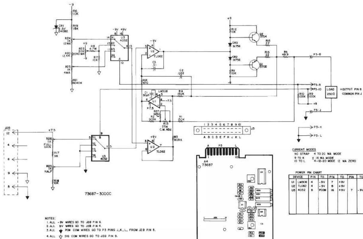
text_image
R6 10K R19 15K R24 12 MA R20 12.4 K R25 1K 4MA R21 9040K +9 +9V +9V U3 4052 I3 I4 X1 X2 X3 X4 A -9V +9V -9V +9V -9V +9V -9V +9V -9V +9V -9V +9V -9V +9V -9V +9V -9V +9V -9V +9V -9V +9V -9V +9V -9V +9V -9N 15X2 11X3 11X4 11X5 11X6 11X7 11X8 11X9 11X10 11X11 11X12 11X13 11X14 11X15 11X16 11X17 11X18 11X19 11X20 11X21 11X22 11X23 11X24 11X25 11X26 11X27 11X28 11X29 11X30 11X31 11X32 11X33 11X34 11X35 11X36 11X37 11X38 11X39 11X40 11X41 11X42 11X43 11X44 11X45 11X46 11X47 11X48 11X49 11X50 11X51 11X52 11X53 11X54 11X55 11X56 11X57 11X58 11X59 11X60 11X61 11X62 11X63 11X64 11X65 11X66 11X67 11X68 11X69 11X70 L308 3 3 3 3 3 3 3 3 3 3 3 3 3 3 3 3 3 3 3 3 3 3 3 3 3 3 3 3 3 3 3 3 3 3 3 3 3 3 3 3 3 3 3 3 3 3 3 3 3 3 0 P3-S B P3-ID P3-L D LOAD + OUTPUT PIN B COMMON PIN J + CURRENT MODES NO STAP 4 TO 20 MA MODE 9 TO K ± 16 MA MODE 4-Ⅱ-20 MODE I2 MA ZERO A B C D E F H U K L A4 T73687 POWER PIN CHART DEVICE PIN TO PIN TO PIN TO UI LM3CE 4 -9V 7 +9V U2 TLO62 4 -9V B PCOM 8 +9V I6 +9V 7 -9V U5 4052 B| CSP | C | 7-1-96 | WAS VERSION 003 | 50 | |
| TT | B | 2-7-96 | REV. 884 NO 81 | MAY | |
| A | G-24-96 | DATE: 10/07/2010 | M | ||
| ZONE | REV | DATED | DESCRIPTION | APR | CONTROL |
| CHL DCT | CSP | DAYTRONIC CORPORATION MIANSBURG, OHIO | |||
| CLM DTT | DFT | ||||
| DATE | 7-12-93 | REV. 7-1-96 | REV. LEVEL | C | |
| 4 TO 20 MA CURRENT OUTPUT CARD | s3000C NUMBER | ||||
3000 SERIES
"G" Option
DUAL GALVANIC ISOLATED OUTPUT
INSTRUCTION MANUAL
1. General Description
With this optional circuit board, a Form 1 (“31XX”) or Form 2 (“32XX”) instrument can furnish two independent galvanic outputs, fully isolated not only from each other but also from the 3000 instrument’s “common.” Each output is normally set at the factory for a full-scale range of 0-10 V-DC (±0.2%) when the data signal from the 3000 unit’s conditioner card is at its standard 5-V level. Though normally preset at “2.00,” each input’s gain can be adjusted within ±5%, if desired, by means of potentiometer controls on the G-option card.
The use of galvanically isolated outputs prevents ground-loop effects in interconnections with remote data-acquisition systems or controllers. The presence of two independent outputs lets you send collected data to two different systems or devices, each with its own ground.
Load limit for each output exceeds 10 kilohms. Output bandwidth is normally 40 Hz; the "G" option can be easily modified, however, for other bandwidths up to 500 Hz (contact the factory for details).
NOTE: The only other options that may be combined with the "G" option are the "B" (battery-powered) and "F" (230 V-AC-powered) options.
2. Additional 3000(G) Specifications
Output Range: ±10 V-DC full scale (2 mA max), normal; internal controls give approximately ±5% of adjustment authority on both SPAN and ZERO
Common-Mode Range: ±500 V, max
Common-Mode Rejection Ratio: DC: -120 dB; at 60 Hz: -60 dB
Linearity: ±0.1% of full scale
Maximum Zero Drift, After Warmup of One-Half Hour: ±0.2% of full scale*
Maximum Span Drift, After Warmup of One-Half Hour: ±0.2% of full scale*
* Applies to the 3000 "G" Option only and does not include possible drift contributed by the signal conditioner board of the base 3000 instrument.
3. Installation and Cabling
When viewing the 3000 instrument from the rear, the Galvanic Output Board is in the upper left of the rear panel (see Fig. 1). Access to the output signals is through a 20-pin edge card connector with a key slot between contact pads 4 and 5. The user must provide his own cable connection to the card, pinout for which is as follows:
Pin No. (see Fig. 1) Function
2,B SIGNAL 1 OUT
1,A,3,C ISO COM 1
9,K SIGNAL 2 OUT
8,J,10,L ISO COM 2
Cabling of the isolated analog outputs is shown in Fig. 2. Each output is single-ended and returns to its own ISO-LATED COMMON. Each output's SHIELD should be tied to the instrument chassis via one of the screws holding the rear panel.
4. Calibration
NO ADJUSTMENT OF THE G OPTION IS NECESSARY DURING NORMAL USE.** Follow the normal calibration procedure given in the respective 3000 Instrument Instruction Manual.
** As mentioned above, separate ZERO and SPAN adjustment controls are provided on the G Option board for each isolated output, if it is desired to refine the "2.00" gain to which the output has been set prior to shipment. These controls, shown in Fig. 3, may be accessed by removing the 3000 instrument's front panel.
Fig. 1
Rear-Panel
Location of
3000G Galvanic
Output Board
Pinout for I/O Connectors (REAR VIEW)


text_image
3000 "G Option" Board I/O Connector (20-pin) Pin 1 Pin 10 Pin A Pin L Conditioner Board I/O Connector (20-pin)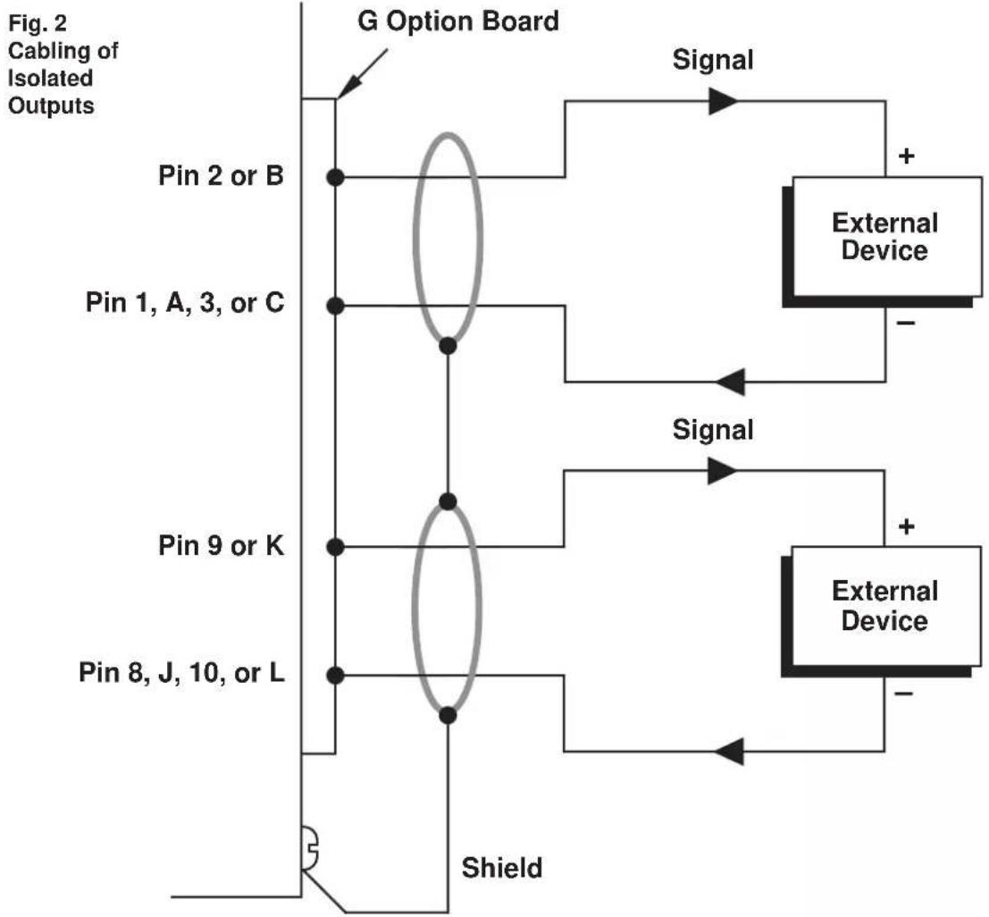
flowchart
graph TD
    A["Pin 2 or B"] --> B["G Option Board"]
    C["Pin 1, A, 3, or C"] --> B
    D["Pin 9 or K"] --> B
    E["Pin 8, J, 10, or L"] --> B
    B --> F["Shield"]
    F --> G["External Device"]
    G --> H["Signal"]
    H --> I["+"]
    H --> J["-"]
    style A fill:#f9f,stroke:#333
    style C fill:#f9f,stroke:#333
    style D fill:#f9f,stroke:#333
    style E fill:#f9f,stroke:#333
    style F fill:#ccf,stroke:#333
    style G fill:#cff,stroke:#333
    style H fill:#ffc,stroke:#333
    style I fill:#cfc,stroke:#333
    style J fill:#cfc,stroke:#333
Fig. 3 Location of Internal G-Option Controls

text_image
FRONT VIEW 3100G CARD CONTROLS LOCATED BEHIND FRONT PANEL. Conditioner CARD
text_image
ISOLATION GUARD P3 P34 P35 R120 U103 R118 49.0K C110 .00uF R119 680K R117 180K R115 100K R113 100K R112 900K C107 .01uF U102 + ISO 1 SUPPLY (+15V) R103 120K - ISO 1 SUPPLY (-15V) R104 1K C105.1uF C106.2uF C107.3uF C108.4uF C109.5uF C110.6uF C111.7uF C112.8uF C113.9uF C114.0uF C115.1uF C116.2uF C117.3uF C118.4uF C119.5uF C120.6uF C121.7uF C122.8uF C123.9uF C124.0uF C125.1uF C126.2uF C127.3uF C128.4uF C129.5uF C130.6uF C131.7uF C132.8uF C133.9uF C134.0uF C135.1uF C136.2uF C137.3uF C138.4uF C139.5uF C140.6uF C141.7uF C142.8uF C143.9uF C144.0uF C145.1uF C146.2uF C147.3uF C148.4uF C149.5uF C150.6uF C151.7uF C152.8uF C153.9uF C154.0uF C155.1uF C156.2uF C157.3uF C158.4uF C159.5uF C160.6uF C161.7uF C162.8uF C163.9uF C164.0uF C165.1uF C166.2uF C167.3uF C168.4uF C169.5uF C170.6uF C171.7uF C172.8uF C173.9uF C174.0uF C175.1uF C176.2uF C177.3uF C178.4uF C179.5uF C180.6uF C181.7uF C182.8uF C183.9uF C184.0uF C185.1uF C186.2uF C187.3uF C188.4uF C189.5uF C190.6uF C191.7uF C192.8uF C193.9uF C200.0kΩ/Ω/Ω/Ω/Ω/Ω/Ω/Ω/Ω/Ω/Ω/Ω/Ω/Ω/Ω/Ω/Ω/Ω/Ω/Ω/Ω/Ω/Ω/Ω/Ω/Ω/Ω/Ω/Ω/Ω/Ω/Ω/Ω/Ω/Ω/Ω/Ω/Ω/Ω/Ω/Ω/Ω/Ω/Ω/Ω/Ω/Ω/Ω/Ω/Ω/Ω/ ISOLATION GUARD P34A P34B P34B(A) P34B(B) P34B(C) P34B(D) P34B(E) P34B(F) P34B(G) P34B(H) P34B(I) P34B(J) P34B(K) P34B(L) P34B(M) P34B(N) P34B(O) P34B(P) P34B(Q) P34B(R) P34B(S) P34B(T) P34B(U) P34B(V) P34B(X) P34B(Y) P34B(Z) P34B(C) P34B(D) P34B(E) P34B(F) P34B(G) P34B(H) P34B(I) P34B(J) P34B(K) P34B(L) P34B(M) P34B(N) P34B(O) P34B(P) P34B(Q) P34B(R) P35A(0)A(0)A(0)A(0)A(0)A(0)A(0)A(0)A(0)A(0)A(0)A(0)A(0)A(0)A(0)A(0)A(0)A(0)A(0)A(0)A(0)A(0)A(0)A(0)A(0)A(0) ISOLATION GUARD P34A(0)A(0)A(0)A(0)A(0)A(0)A(0)A(0)A(0)A(0)A(0)A(0)A(0)A(0)A(0)A(0)A(0)A(0)A(0)A(0) ISOLATION GUARD (CHANNEL 2 ZERO) + ISO 2 SUPPLY (+15V) + ISO 2 SUPPLY (-15V) + ISO 2 SUPPLY (+25V) + ISO 2 SUPPLY (-25V) + ISO 2 SUPPLY (+25V) + ISO 2 SUPPLY (-25V) + ISO 2 SUPPLY (+25V) + ISO 2 SUPPLY (-25V) + ISO 2 SUPPLY (+25V) + ISO 2 SUPPLY (-25V) + ISO 2 SUPPLY (+25V) + ISO 2 SUPPLY (-25V) + ISO 2 SUPPLY (+2Sv)(E)(G)(H)(I)(J)(K)(L)(M)(N)(O)(P)(Q)(R)(S)(T)(U)(V)(W)(X)(Y)(Z)(W)(X)(Y)(Z)(W)(X)(Y)(Z)(W)(X)(Y)(Z)(W)(X)(Y)(Z)(W)(X)(Y)(Z)(W)(X)(Y)(Z)(W)(X)(Y)(Z)(W)(X)(Y)(Z)(W)(X)(Y)(Z)(W)(X)(Y)(Z)(W)(X)(Y)(Z)(W)(X)(Y)(Z)(W)(Y) ISOLATION GUARD (RIO 2 SULCS) + ISO 2 SUPPLY (+25V) + ISO 2 SUPPLY (-25V) + ISO 2 SUPPLY (+25V) + ISO 2 SUPPLY (-25V) + ISO 2 SUPPLY (+2Sv)(E)(G)(H)(I)(J)(K)(L)(M)(N)(O)(P)(Q)(R)(S)(T)(U)(V)(W)(X)(X)(Y)(Z)(W)(X)(Y)(Z)(W)(X)(Y)(Z)(W)(X)(Y)(Z)(W)(X)(Y)(Z)(W)(X)(Y) ISOLATION GUARD (RIO 2 SULCS) + ISO 2 SUPPLY (+25V) + ISO 2 SUPPLY (-25V) + ISO 2 SUPPLY (+2Sv)(E)(G)(H)(I)(J)(K)(L)(M)(N)(O)(P)(Q)(R)(S)(T)(U)(V)(W)(X)(X)(Y)(Z)(W)(X)(Y)(Z)(W)(X)(Y)(Z)(W)| CSR | I | 11-18-98 | BEX 20000 | OCH |
| CSR | H | 9-5-97 | BEX 9770 | EF8 |
| CSR | 6 | 7-1-96 | NEW VERSON 800 | SES |
| SLS | F | 3-24-94 | CORRECTED 7000 | FN |
| SLS | E | 2-24-94 | DWG. FIN 5 70 & 8200 | FN |
| CLM | D | 4-9-93 | BEX 800-4940 | MN |
| C | 11-29-90 | DBX WEL. ALCT-4618 WHIT-REACH AND CHILL | MN | |
| B | 10-31-90 | DWG. FIN 56180 | MN | |
| A | 8-2-98 | AWGD 516-036 WITH GROUP DENT, NO. A | MN | |
| DFT. | REV. | DATED | DESCRIPTION | APP. CONTROL |
| DSA DES. | DSA CH#. | DAYTRONIC CORPORATION | MIKANSBURG, OHIO | |
| KTS DFT. | FX AP. | |||
| DATE | 1-12-67 | REV 11-18-98 | REV. LEVEL. I | |
| GALVANIC ISOLATED OUTPUT NAME OPTION CARD (3100G) | s3000G NUMBER | |||
3000 SERIES
"P" Option
ANALOG PEAK CAPTURE
INSTRUCTION MANUAL
1. General Description
With the installation of a special "P" version of the 3000 Series HI-LO LIMITS board (shown in Figure 2, below), real-time analog peak capture is possible for a Form 2 ("32XX") or Form 3 ("33XX") instrument, in addition to its normal "tracking" function. ^1
Controlled either by front-panel push buttons (Fig. 1) or by a remote user-installed switch (Fig. 3), a "P" unit can "freeze" and display the last positive input-signal "peak" value to have been perceived. The analog output is held at this value until a TRACK/RESET command is applied. ^2 A subsequent higher signal excursion disables the "hold," permitting the capture of subsequent higher peaks. Because it is digitally held, a displayed peak value will not decay. The maximum decay rate for a held analog output is only 0.1% of full scale per minute.
For capture of negative “peaks” (signal minima), the input lines may be inverted.
With all Form 3 instruments, limits are automatically latched upon peak capture, and are automatically reset on return to normal TRACK mode. See the Model 3300 HI-LO Limits Instruction Manual for complete details regarding limit setup and operation (including mode selection, setting of limit setpoint values, and logic output connections for annunciation and control). For selection of engineering-unit digital range and resolution, see the Model 3200/3300 Digital Indicator Instruction Manual.
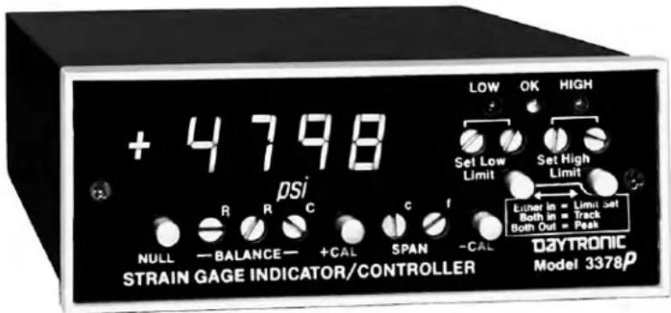
text_image
+ 4798 psi NULL — BALANCE — +CAL SPAN -CAL CONSTAIN GAGE INDICATOR/CONTROLLER DAYTRONIC Model 3378p LOW OK HIGH Set Low Limit Set High Limit Eunder in = Limit Set Both in = Track Both Out = PeakFig. 1 Model 3378P Front Panel, showing push buttons for Peak / Track control
Pinout for I/O Connectors (REAR VIEW)

Fig. 2
Rear-Panel
Location of
3000P Peak
Capture
Board
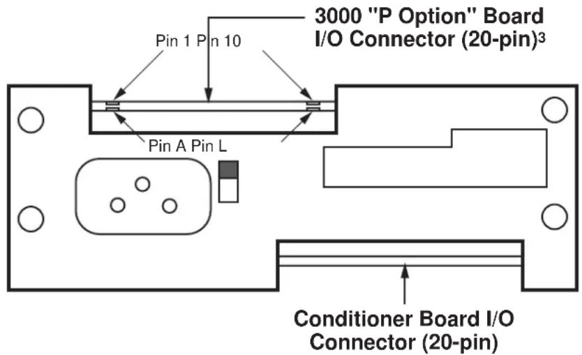
text_image
3000 "P Option" Board I/O Connector (20-pin)³ Pin 1 Pin 10 Pin A Pin L Conditioner Board I/O Connector (20-pin)1 NOTE: The "P" Option may NOT be used in combination with the "C," "G," R," or "S" Option.
^2 To prevent low-level signal noise from triggering a "peak hold," the peak capture function is automatically disabled when the input is less than 8% of full scale. If you require peak capture within the 0-8% range, contact the factory.
^3 In Form 3 (“33XX”) instruments with the “P” Option, peak-capture circuitry is integrated with the 3300 HI-LO Limits Board.
2. Connections
Pin assignments for the 3000P board's 20-pin I/O connector (shown in Fig. 1) are given in the following table.*
Pin Number Function
| 7 PEAK ANALOG SIGNAL | |
| Holds peak analog input value when in PEAK mode;follows analog input continuously when in TRACK mode | |
| 8 TRACK | |
| Used for external peak reset control (see Fig. 3, below) | |
| 9 SLOW | |
| Tie to Pin K for narrowband-signal peak processing (DC to 2 Hz) | |
| 10 FAST | |
| Tie to Pin K for wideband-signal peak processing (DC to highest available low-pass filter corner frequency) | |
B or J** COMMON
K PEAK RESPONSE SELECT
Tied to Pin 9 or 10 to select narrowband or wideband peak processing, respectively
As indicated in the table, a jumper must be installed between PIN K and either PIN 9 ("SLOW") or PIN 10 ("FAST"), depending on whether you want to capture peaks for a narrowband signal (DC to 2 Hz) or a wideband signal (DC to highest available low-pass filter corner frequency), respectively.
3. Operation
As mentioned above, PEAK/TRACK operation can be locally controlled by front-panel push buttons, while the PEAK RESET function can be remotely controlled by a logic-level command to the rear 3000P connector (when the instrument is set to PEAK mode via the front-panel buttons).
For front-panel control, you will use the two LIMIT SET buttons as follows:
BOTH BUTTONS PRESSED ("IN")
Places the unit in TRACK mode. The analog output at Pin 7 will continuously follow the analog input. This mode is used to reset the instrument following peak capture.
BOTH BUTTONS UNPRESSED ("OUT")
Places the unit in PEAK mode. The analog output at Pin 7 will continuously represent the most positive value experienced by the analog input signal since PEAK mode was last begun.
When (and only when) the instrument is set to PEAK mode via the front-panel buttons, a PEAK RESET can be externally applied by connecting Pin 8 of the rear I/O connector with the COMMON line (Pin B or J**), as shown in Fig. 3. Thus, when these pins are connected via an external contact closure (as in the top diagram of Fig. 3), CLOSING the switch will cause the output at Pin 7 to once again TRACK the analog input, while OPENING the switch will return the output to PEAK mode.
Fig. 3
Track/Reset Via External Command (Switch, Open Collector Transistor, or TTL Logic)

text_image
8 (TRACK) B or J (COMMON)**
text_image
8 (TRACK) B or J (COMMON)**
flowchart
graph TD
    A["8 (TRACK)"] --> B["TTL"]
    C["B or J (COMMON)**"] --> B["TTL"]

text_image
P4 11> 12> 8> FAST ANALOG OUTPUT SLOW ANALOG OUTPUT TO TRACK BUTTONS +9 VOLTS -9 VOLTS DVM HOLD 3> SIGNAL COMMON Q1 2N3704 R13 10K R12 10K U5 1/4 TL074 C7 1uF -9V CR7 1N914 R6 10KMF R8 10KMF R9 10KMF C9 500pF C8 .0047uF R20 10KMF R7 5.6M +9V R11 25K ZERO U2 6 TL071 C9 500pF U6 10 CD4053 Y 15 U6 14 CD4053 X 12 INH VEE 7 -9V CR5 10 FD333 CR6 11 FD333 C4 .1UF C2 .1UF C3 .1UF C4 .1UF C5 .1UF C4 .1UF C3 .1UF C2 .1UF C1 .1UF C1B 1K R21 15M R22 100K R23 1.5M U3 6 TL071 C4 .1UF C3 .1UF C4 .1UF C5 .1UF C4 .1UF C3 .1UF C2 .1UF C1B 6.8K U5 4 TL074 R17 47K R18 150 R22 100K R23 1.5M +9V R4 1M R5 2.2M R6 1/4 TL074 +9V R1 220K C6 2.01uF R2 1.5M U5 8 9 10 TLP 73600 MF DENOTES METAL FILM RESISTOR DENOTES SIGNAL COMMON IC TYPE PIN 10 PIN 10 20, U3 TL071 7 +9 4 -9 U5 TL074 4 +9 11 -9 U6 14053 16 +9 7,8 -9 6-4-97 3200 P P3 CSR O B-4-9E FOR MODE A/C CSR C 7-18-98 MAX VERSIDE 688 SES SLS G 3-1-94 CHRD/P D 73 MELCK FM JFS A 11-18-91 CHRD/WR TO 608 SES OPT. REV. DATID DESCRIPTION APP. CONTROL DPT. OFF. EM. CP. OK. DAYTRONIC CORPORATION HANISBURG, CHIO DATE 12-12-79 REV 9-4-96 REV. LEVEL NAME 3000 PEAK BOARD S3200P NUMBER| CSR | D | 9-4-96 | FOR WM2 | 50 | |
| CSR | C | 7-18-96 | WAS VERSION 999 | SES | |
| SLS | B | 3-1-94 | CHAWAY C 73 WARS | FM | |
| JFS | A | 11-18-91 | CHW. WM TO WM | SES | |
| DFT. | REV. | DATED | DESCRIPTION APP. | CONTROL | |
| DAYTRONIC CORPORATION | |||||
| DATE | 12-12-79 | REV 9-4-96 | REV. LEVEL: D | ||
| NAME | 3000 PEAK BOARD | 53200P | |||
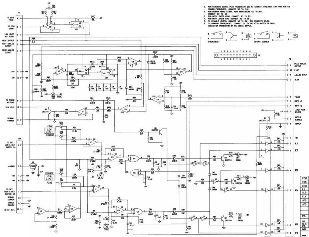
text_image
TO 50-8 POLE TO DYN OUTPUT LOW LIMIT SET POINT PEAK OUTPUT FAST ANALOG OUTPUT SLOW ANALOG OUTPUT +9V +9V 10 +9V 13 3 FINE LOW LIMIT COARSE HUNGER HIGH LIMIT FINE TO SET HIGH LIMIT SWITCH 5A SIGNAL COMMON POWER COMMON +2.5V ROF. 24 4 6 7 8 2 1 2 3 4 5 6 7 8 9 10 11 12 13 14 15 16 17 18 19 20 21 22 23 24 25 26 27 28 29 30 31 32 33 34 35 36 37 38 39 40 41 42 43 44 45 46 47 48 49 50 51 52 53 54 55 56 57 58 59 60 61 62 63 64 65 66 67 68 69 70 71 72 73 74 75 76 77 78 79 80 81 82 83 84 85 86 87 88 89 90 91 92 93 94 95 96 97 98 99 100 101 102 103 104 105 106 107 108 109 110 111 112 113 114 115 116 117 118 119 120 121 122 123 124 125 126 127 128 129 130 131 132 133 134 135 136 137 138 139 140 141 142 143 144 145 146 147 148 149 150 151 152 153 154 155 156 157 158 159 160 161 162 163 164 165 166 167 168 169 170 171 172 173 174 175 176 177 178 179 180 181 182 183 184 185 186 187 188 189 190| IC | TYPE | PEN | TO | PEN | TO |
| U2 | TL074 | 4 | +8 | 11 | -9 |
| U3 | MC1458 | 8 | +5 | 4 | -9 |
| U7, U8, U9 | TL071 | 7 | +8 | 6 | -9 |
| U11 | CD4058 | 16 | +9 | 8, 7, 8 | -9 |
| U4 | CD4070 | 14 | +8 | 7 | -9 |
| U10 | TL074 | 4 | +8 | 11 | -9 |
| U8 | 740814 | 14 | +5 | 7 | P.C. |
| U6 | 75484 | 1 | +5 | 8 | P.C. |
BD. NO. 73613.1 BD. DATE: 1-6-92
| CSR | J | 9-4-96 | SEE ECR 8523 | CA | |
| CSR | H | 7-26-90 | HAS VERS 013 | B | |
| CSR | G | 10-23-95 | SEE ECR 8150 | MW | |
| LL | F | 11-8-94 | SEE ECR 7081 | MW | |
| SLS | E | 5-18-84 | SHERNIE 2070 000 | SS | |
| KLK | D | 5-9-93 | SEE 2000000 | MW | |
| JFS | C | 3-25-92 | SEE 2000000 | MW | |
| JFS | B | 11-18-91 | SEE 2000000, 70 AM | SES | |
| A | 1-17-91 | MW | |||
| SEE 2000000, SEE 2000000, SEE 2000000, SEE 2000000, SEE 2000000, SEE 2000000, SEE 2000000, SEE 2000000, SEE 2000000, SEE 2000000, SEE 2000000, See | |||||
| SBS. | REV. | DATED | DESCRIPTION | APP. | CONTROL |
| DES. | ON. | DAYTRONIC | |||
| SPT. | APP. | CORPORATION | MIAMI-SBURG, OHIO | ||
| DATE | 4-26-90 | REV. | 9-4-96 | REV. | LEVEL |
3000 SERIES
“R” & “S”
Options
INTERNAL RELAY
INSTRUCTION MANUAL
1. General Description
With this option, a Form 3 instrument can switch power for control action in all types of open-loop or ON-OFF closed-loop operations.* It may be used, for example, to actuate alarms or sorting devices, or to start up or shut down external processes. Both relay types are controlled directly by the unit's LIMIT VIOLATION outputs, as shown in Fig. 2.
The Electromechanical Relay (“R” Option) is ideal for DC or low-level switching. Two normally open and two normally closed contacts are rated at 8 amps, 250 V-AC at full resistive load. Switch lifetime at 1 amp resistive load exceeds 100,000 operations.
The Solid-State Relay ("S" Option) is suitable for controlling medium-power AC loads, or for highly repetitive operations (since its lifetime at full resistive load exceeds 10,000,000 operations). Its contacts (similar to those of the Electromechanical Relay) are rated at 3 amps, 250 V-AC at full load. Zero-crossing circuitry ensures low EMI.
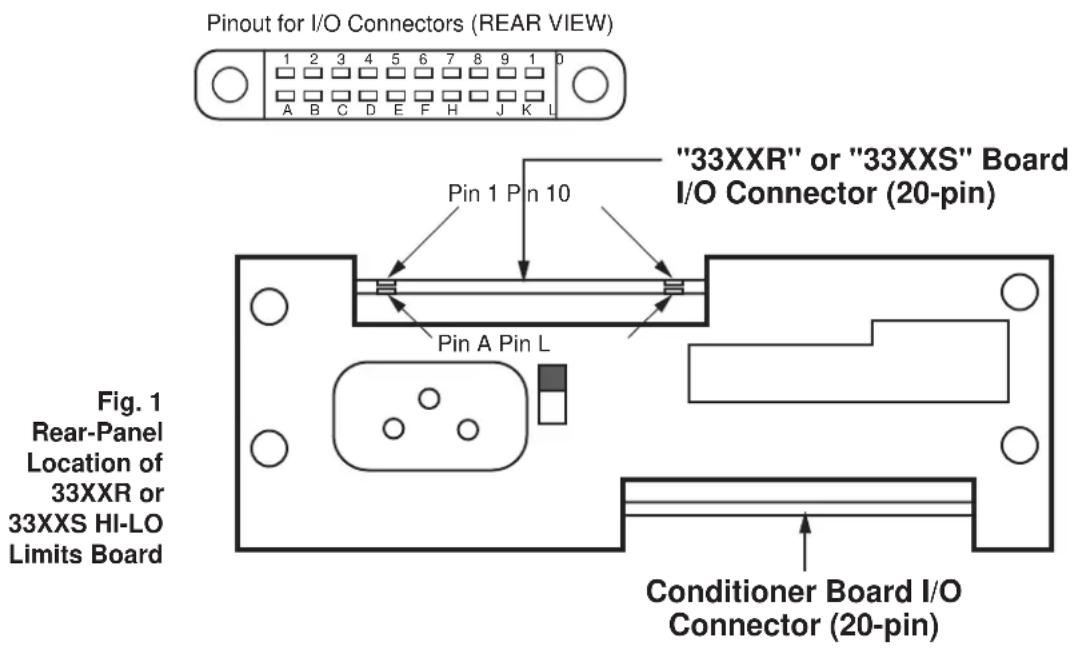
text_image
Pinout for I/O Connectors (REAR VIEW) 1 2 3 4 5 6 7 8 9 1 0 A B C D E F H J K L "33XXR" or "33XXS" Board I/O Connector (20-pin) Pin 1 Pin 10 Pin A Pin L Fig. 1 Rear-Panel Location of 33XXR or 33XXS HI-LO Limits Board Conditioner Board I/O Connector (20-pin)2. Connections
Relay pin assignments for the limit board's 20-pin I/O connector (shown in Fig. 1) are given in the diagram on the next page. For all other (limit-related) I/O connections, see the Model 3300 HI-LO Limits Instruction Manual.

text_image
33XX HI-LO LIMITS BOARD WITH "R" OR "S" OPTION Rear I/O Connector L 10 K 9 J 8 H 7 QLO Normally open; closed when LOW LIMIT is violated QLO Normally closed; opened when LOW LIMIT is violated QHI Normally open; closed when HIGH LIMIT is violated QHI Normally closed; opened when HIGH LIMIT is violated Fig. 2 Relay Pin Connections for "R" and "S" OptionsInternal relays shown in "OK" (NO VIOLATION) mode
Fig. 2

text_image
REAR CONNECTOR L 10 K 9 J 8 H 7 J2B PINS 3 5 + UNREG. QLO QLO 6 7 8 5 6 RELAYS AROMAT STIE - DC12V 28174 + UNREG. CRIO IN914 Q7 2N3704 R44 IOK LO LIMIT FROM U5 PIN 2 J Q HI 7 8 5 6 K1 28174 + UNREG. CR9 IN914 Q6 2N3704 R43 IOK HI LIMIT FROM U5 PIN 6 RELAYS DRAWN IN "OK" MODE (NO VIOLATION) 73723-3300"R" OPTION CINCUIT BD. DATE - 3-4-85CSR B 3-8-96 SEE ECR 835T CSR A 10-25-95 SEE ECR 8151
| RAL DES. | CHK. | DAYTRONICCORPORATION MIAMISBURG.OHIO | |
| GST OFT. | MUS APP | ||
| DATE: 12-8-83 | REV: 3-8-96 | REV. LEVEL: A | |
| 3300 "R" OPTION NAME | s330OR NUMBER | ||
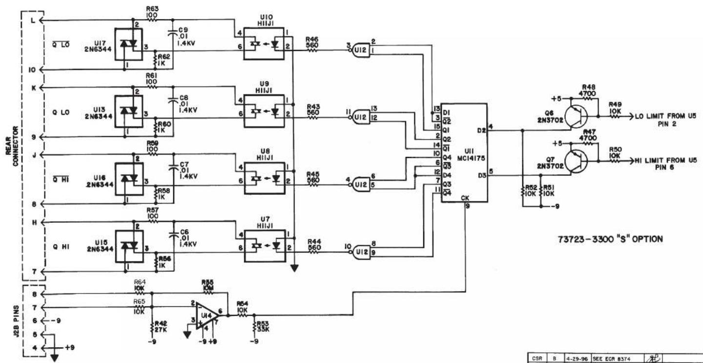
text_image
L Q LO U17 2N6344 R63 100 C9 .01 1.4KV R62 1K U10 HIIJI 4 6 2 R46 560 3 U12 2 I0 K R61 100 C8 .01 1.4KV U9 HIIJI 4 6 2 R43 560 11 U12 13 J Q LO U13 2N6344 R59 100 C7 .01 1.4KV U8 HIIJI 4 6 2 R45 560 4 U12 5 Q HI U16 2N6344 R58 1K C7 .01 1.4KV U7 HIIJI 4 6 2 R44 560 10 U12 8 H Q HI U15 2N6344 R57 100 C6 .01 1.4KV U7 HIIJI 4 6 2 R44 560 10 U12 9 J2B PINS 8 7 6 -9 5 4 +9 R64 10K R55 10K R48 27K R53 35K R55 ICM U14 7-9+9-9-9-9-9-9-9-9-9-9-9-9-9-9-9-9-9-9-9-9-9-9-9-9-9-9-9-9-9-9-9-9-9-9-9-9-9-9-9-9-9-9-9-9-9-9-9-9-9-9-9- 73723-3300 "S" OPTIONBD. NO. 73723
BD DATE: 3-4-85
| CSR | B | 4-29-96 | SEE ECR 8374 | ||
| CSR | A | C-26-95 | SEE ECR 8155 | ||
| ZONE | REV. | DATED | DESCRIPTION | APP. | CONTROL |
| RAL DES. | CHK. | DAYTRONIC CORPORATION MIAMIISBURG, OHIO | |||
| GST DFT. | APR | ||||
| DATE: 12-6-83 | REV: 4-29-96 | REV. LEVEL: A | |||
| 3300 "S" OPTION | s3300S NUMBER | ||||

DAYTRONIC
Daytronic Corporation
Dayton, OH · (800) 668-4745
www.daytronic.com