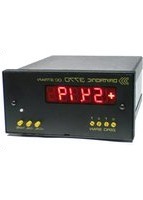
3770DCP - Measurement Daytronic - Free user manual and instructions
Find the device manual for free 3770DCP Daytronic in PDF.


| Product Type | Strain Gage Indicator/Controller |
| Display | 4.5-digit LED, 0.56" height |
| Input Configuration | Quarter, half, or full bridge |
| Excitation Voltage | 5 V or 10 V DC, selectable |
| Accuracy | ±0.05% of reading ±1 count |
| Analog Output | ±10 V DC, 4-20 mA optional |
| Communication | RS-232 serial interface |
| Alarm Setpoints | Two independent setpoints with relay outputs |
| Special Functions | Peak hold, tare, auto-zero, digital filter |
| Power Supply | 115/230 VAC, 50/60 Hz, or 9-32 VDC |
| Power Consumption | 6 VA typical |
| Dimensions (W×H×D) | 8.5 × 3.5 × 10 inches (216 × 89 × 254 mm) |
| Panel Cutout | 7.2 × 2.9 inches (183 × 74 mm) |
| Weight | 4.5 lbs (2.04 kg) |
| Operating Temperature | 0 to 50 °C (32 to 122 °F) |
| Storage Temperature | -20 to 70 °C (-4 to 158 °F) |
| Enclosure | Panel mount, steel with painted finish |
| Safety | Overvoltage protection on input and power |
| Maintenance | Annual calibration recommended; clean with dry cloth |
| Accessories Included | User manual, power cord, mating connector |
| Repair / Service | Contact Daytronic or authorized service center |
Frequently Asked Questions - 3770DCP Daytronic
User questions about 3770DCP Daytronic
0 question about this device. Answer the ones you know or ask your own.
Ask a new question about this device
Download the instructions for your Measurement in PDF format for free! Find your manual 3770DCP - Daytronic and take your electronic device back in hand. On this page are published all the documents necessary for the use of your device. 3770DCP by Daytronic.
USER MANUAL 3770DCP Daytronic
Death, serious injury, or fire hazard could result from improper connection of this instrument. Read and understand this manual before connecting this instrument. Follow all installation and operating instructions while using this instrument.
Connection of this instrument must be performed in compliance with the National Electrical Code (ANSI/NFPA 70-2014) of USA and any additional safety requirements applicable to your installation.
Installation, operation, and maintenance of this instrument must be performed by qualified personnel only. The National Electrical Code defines a qualified person as “one who has demonstrated the skills and knowledge related to the construction and operation of the electrical equipment and installations, and who has received safety training on the hazards involved.”
Qualified personnel who work on or near exposed energized electrical conductors must follow applicable safety related work practices and procedures including appropriate personal protective equipment in compliance with the Standard for Electrical Safety Requirements for Employee Workplaces (ANSI/NFPA 70E-2012) of USA and any additional workplace safety requirements applicable to your installation.
ADVERTENCIA
The following safety precautions must be followed whenever any type of voltage or current connection is being made to the instrument.
Before connecting to electric circuits or pulse initiating equipment, open their related breakers or disconnects. It is recommended NOT TO install any connection of the instrument on live power lines. Only Qualified Service personnel that have demonstrated the abilities and received the proper safety training are capable of connecting to live circuits.
- Connections must be made to the instrument first, then connect to the circuit to be monitored.
- Wear proper personal protective equipment, including safety glasses and insulated gloves when making connections to power circuits.
- Hands, shoes and floor must be dry when making any connection to a power line.
Before each use, inspect all cables for breaks or cracks in the insulation. Replace immediately if defective.
If the equipment is used in a manner not specified in this user's guide, the protection provided by the equipment may be impaired.
Standard Accessories
Standard accessories
The following table lists the 3700 standard accessories.
| Description Part Number | |
| 3770 Manual | 92363.00 |
| 3770 Quick Reference Guide | 92368.00 |
| 5 Pin connector, analog signals | 25657-LF |
| 8 Pin connector, transducer | 25658-LF |
| 10 Pin connector, logic | 25606.00 |
| *US Power Cord | USSTDCORD (900744) |
| *European Power Cord | EUROSTDCORD (115369-G1) |
| *United Kingdom Power Cord | UKSTDCORD (115368-G2) |
| *Australian Power Cord | AUSTDCORD (901347) |
| Desk top feet (4ea.) | 35058.00 |
| *User specified, one standard only. | |
1 GENERAL DESCRIPTION AND SPECIFICATIONS
The Model 3770 is a single-channel panel instrument for traditional wheat-stone bridge type sensors; intended for applications involving conventional full arm bridges from 120 to 10K Ohm transducers with mV/V ratings between 0.5 and 10.0 mV/V full scale. The 3770 will supply excitation, conditioning and provide a calibrated Engineering Unit's display and analog output signals for the measurement of force, load, torque, pressure and other parameters associated with DC based full bridge sensors. The 3770 is front panel configurable with user selectable wide gain, zero, symmetry, and selectable analog output of voltage and current signals. Display is user configured and can be independently adjustable for engineering unit scaling up to ± 199950 independent of the analog full scale signal.
The Model 3770 can be either calibrated by the “two-point (dead-weight)” process involving known input parameters or through the “Shunt” method using front panel push buttons or rear connections for simulated calibration using a known resistance provided internally by the 3770 or through a user installed resistor value.
FRONT PANEL VIEW OF 3770 CONTROLS (Front Display Cover Removed)

3770 SPECIFICATIONS
Measurement Range: Adjustable; 0.5 to 10 mV/V; nominal full-scale. Dependent on Excitation level selected
Transducer Types: Conventional 4-arm strain gage bridges, 120 to 10 k ohm
Excitation: Selectable: 5.0 or 10.0 Vdc, with remote sense lines. Up to 70 mA.
Power Supply: Voltage 90 - 250 VAC, 47 -63 Hz Consumption 10 Watts
Physical Parameters: 5.68" W x 2.84" H x 7.06" D; weight - 3.25 Lbs.
Analog Output: selectable; ± 5, ±1.0 VDC, 4 -20 mA or 4 -12 -20 mA (20 % over -range on voltage outputs only)
Operating Temperature: 0 to +55 Degrees C, 5 to 95% relative humidity, non-condensing
Altitude: 2000m (6560 ft) maximum
Installation Category: Installation Category II, Pollution Degree 2
Amplifier
Normal - Mode Range: ± 0.2 V RMS operating; ± 28 V without instrument damage
Common - Mode Range: ± 3 V
Input Impedance: Differential >10 MΩ
Offset: vs. Temperature: ±30 ppm μV/°C; vs. Time: ±10 ppm/month
Gain Accuracy: Limited only by calibration accuracy
Gain Stability: vs. Temperature: ±30 ppm/°C; vs. Time: ±10 ppm/month
Linearity: better than ± 0.03% of full scale
Filter: 3-pole modified Butterworth; 3 dB down at 2 Hz, 20 Hz or 200 Hz; selectable.
Fast output always enabled, 5 KHz response (J3 Pin 3).
Step-Response Settling Times for the 3770 (in milliseconds)
| 3db Frequency | To within 1% | within .1% | within .02% | |
| Fast Output | 5000 Hz | 0.14 | 0.10 | 0.08 |
| Selectable Output | 200 Hz | 3.7 | 5.0 | 5.6 |
| 20 Hz | 37 | 50 | 56 | |
| 2 Hz | 370 | 500 | 560 |
1. a PANEL MOUNTING
You can easily mount the instrument in your own precut panel. Cutout dimensions for a panel-mounted unit are standard DIN; panel thickness should not exceed 6 mm (0.24 in). Simply unscrew the two rear-panel CLAMP SCREWS and slide the CLAMP SLIDES rearwards out of their grooves (THE FRONT BEZEL NEED NOT BE REMOVED). Insert the unit through the panel cutout, from the front of the panel (if the unit has rubber feet, these will have to be removed). Then reinstall the CLAMP SLIDES, and tighten the CLAMP SCREWS until the instrument is securely mounted.

2 CONNECTIONS
The Model 3770 I/O CONNECTIONS are via removable screw terminals which will accept wire sizes from AWG 12 to 26. NOTE: The recommended transducer cabling would be eight wire, twisted pair, individually shielded - wired as indicated (Fig. 6) Sense lines must be connected at the transducer (as recommended) or at the 3770 screw terminals - as a minimum. Table 1 denotes screw terminal assignments
Rear Panel Connections
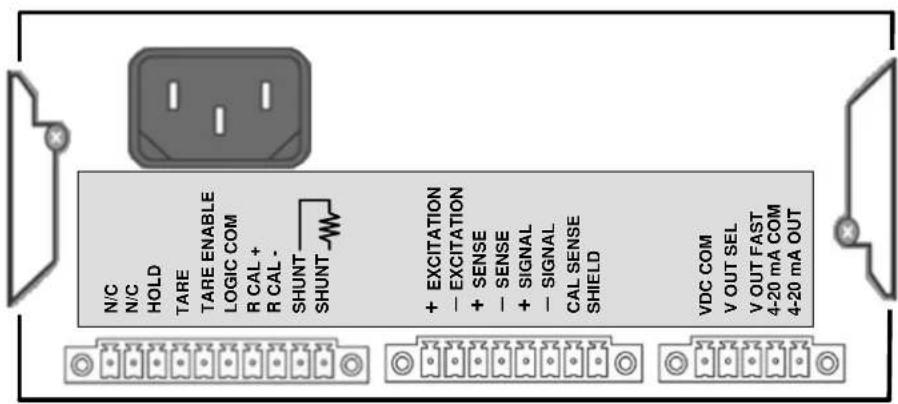
Table 1
| Connector Number | Screw Terminal | Terminal Label | Function |
| J1 1 N/C No connection | |||
| J1 2 N/C No connection | |||
| J1 | 3 | HOLD | Input Analog Hold command |
| J1 | 4 | TARE | Input Analog TARE command |
| J1 | 5 | TARE ENABLE | External TARE enable input |
| J1 | 6 | LOGIC COM | Logic Common |
| J1 | 7 | R CAL + | Remote Positive SHUNT Command |
| J1 | 8 | R CAL - | Remote Negative SHUNT Command |
| J1 | 9 | SHUNT | External Shunt Resistor Connection |
| J1 | 10 | SHUNT | External Shunt Resistor Connection |
| J2 | 1 | + EXCITATION | + Excitation Power |
| J2 | 2 | - EXCITATION | - Excitation Power |
| J2 | 3 | + SENSE | + Sense excitation control |
| J2 | 4 | - SENSE | - Sense excitation control |
| J2 | 5 | + SIGNAL | + Signal Input from sensor |
| J2 | 6 | - SIGNAL | - Signal Input from sensor |
| J2 | 7 | CAL SENSE | Calibration Sense for Shunt |
| J2 | 8 | SHIELD | Case Shield for cable termination |
| J3 | 1 | VDC COM | - Signal Output Voltage Common |
| J3 | 2 | V OUT SEL | + Signal Output Voltage – Filter Select |
| J3 | 3 | V OUT FAST | + Signal Output Voltage – 5 kHz Filter |
| J3 | 4 | 4-20 mA COM | Current Output Common |
| J3 | 5 | 4-20 mA OUT | Current Output Signal |
2 CONNECTIONS
J1 – Shunt Resistor Connections. Two terminal pins are provided via the J1 rear connector for installation of an external shunt resistor. Terminal connections are used to install a user defined resistor as determined by the sensor's calibration data sheet or pre-determined by the user. When an externally installed resistor is used, the ANALOG CONTROL switch 5 is required to be in the External position (Switch 5 DOWN).
Note: The 3770 unit comes with an internally installed 59K Ohm resistor, as standard, and enabled when the front panel ANALOG CONTROL Switch# 5 is in the Internal position (Switch 5 UP).
Note: When a sensor has an integrated shunt resistor, the ANALOG CONTROL switch setting needs to be in the External position and a shorting wire in place of the external shunt resistor position. This provides the electrical path for the Calibration Sense line to enable the sensor's internal shunt resistor when the + or - Shunt Calibration rear terminals or push buttons are activated.

NOTE: Daytronic Shunt Calibration circuit, when activated, will place the Shuntresistor across the +Sense Line (for positive shunt) or the -Sense Line (for negative shunt) with the connection of the Sensor's Calibration Sense line located on the J2 connector - which is recommend to be connected to the +Signa 1 line. When not activated, the Calibration Sense line is buffered as to not affect the sensor's operational characteristics.
2 CONNECTIONS
J1 – Shunt Command Connections. Connection is used to activate the positive or negative Shunt calibration command from the rear panel. When the + or - R CAL terminal is connected to LOGIC COM via a switch or relay, the installed Shunt resistor will be connected across + Signal and + Sense or - Sense depending on the Shunt polarity chosen and the CAL SENSE connection. CAL SENSE line is normally connected to + Signal for proper signal activation.
Fig. 4

SHUNT Command Connections
J1 - SHUNT Activation Connections
Connecting LOG COMMON to the R CAL + or R CAL - terminal will activate the installed shunt resistor (internal or external) across the connected four arm bridge sensor for simulated calibration & verification check of the sensor's electrical characteristics.
J2 - HOLD & TARE Connections. Connection is used when external control of the "HOLD" or "TARE" features of the unit are enabled and are controlled by an external switch, PLC or relay. The LOGIC COM signal is used to activate the analog HOLD or Analog TARE (offset) to the meter's display and analog output signals present on J3.
Fig. 5
J1 Logic Controls
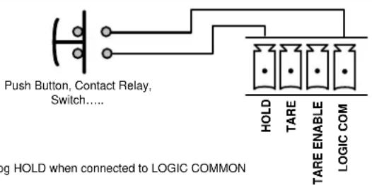
HOLD IN
Activates Analog HOLD when connected to LOGIC COMMON
TARE IN
Activates Analog TARE when connected to LOGIC COMMON
TARE ENABLE
Enables remote TARE and disables front panel TARE when connected to LOGIC COMMON
LOGIC COMMON
Connection to enable rear panel features
WARNING
Qualified personnel who work on or near exposed energized electrical conductors must follow applicable safety related work practices and procedures including appropriate personal protective equipment in compliance with the Standard for Electrical Safety Requirements for Employee Workplaces (ANSI/NFPA 70E-2012) of USA and any additional workplace safety requirements applicable to your installation.
Fig. 6 - Transducer Cabling - DC Strain Gage- J2
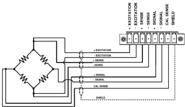
Note: Sense lines must be connected at the transducer or at the instrument for proper operation.
J3 - Analog Connections Provides analog outputs from the meter's signal conditioning area in the form of ±5Vdc or ±10 Vdc (selectable via the front panel controls) and 4-20 mA (or selectable 4-12-20 mA). Full scale output is referenced to the display "range" selected (5000, 10000, or 20000). I.e. If range 10000 is selected, the analog output will be 5 Vdc or 10 Vdc, as determined by the front panel controls (or 20 mA FS) when in the default/home position and the display reads 10000 (irrespective of the decimal point).

J3 - Analog Output Connections
Pin 1 Voltage Common (- Signal out) reference for Pin 2 and Pin 3 + Signal Voltage Output.
Pin 2 Voltage Output Selected (+Signal out) reference to Pin 1. The Full Scale Voltage is determined by the position of switch 1 - VDC on the Conditioner Controls. Output response is determined by the position of switch 3-FIL and 4-FIL on the Analog Controls.
Pin 3 Voltage Output Fixed. (+ Signal out) reference to Pin 1. Full Scale Voltage is determined by the position of switch 1-VDC of the Conditioner Controls. Filter response is fixed at the highest analog signal response of 5KHz .
Pin 4 4-20 mA Current Output Common (- Signal) reference for Pin 5 Current Output.
Pin 5 4-20 mA Current Output (+Signal) reference to Pin 4 Current Output Common. The Current Output is selectable for 4 - 20 mA or 4-12-20 mA as determined by the position of switch 2 -mA of the Conditioner Control switch(s) on the Front Panel.
3 CONTROLS
Display Range and Decimal Point Selection

Switch 1 - selects decimal point for position X.XXXXX
Switch 2 - selects decimal point for position XX.XXXX
Switch 3 - selects decimal point for position XXX.XXX
Switch 4 - selects decimal point for position XXXX.XX
Switch 5 - enables dummy zero display digit XXXXX0
Switch 6 & 7 - selects Display Full Scale Range.
Range will equate to an analog output value of ±5 Vdc or ±10 Vdc per Analog Control switch placement. Selection is set for 1 count in 5000, 2 counts in 10000 and 5 counts in 20000.
Analog Zero and Span Adjustments

Coarse Zero - 22 Turn potentiometer adjustment for balance control of analog offset signal
Fine Zero - 25 Turn potentiometer for fine balance control of analog offset signal
Coarse Span - 22 Turn potentiometer adjustment for analog control of gain
Fine Span - 25 Turn potentiometer adjustment for analog control of fine gain
Analog Wide Gain and Zero Controls
Two - 16 Position switches are used for wide control adjustment of the analog output signal from the 3770 meter; this in turn affects the digital readout for engineering unit's adjustments as determined by the display settings.
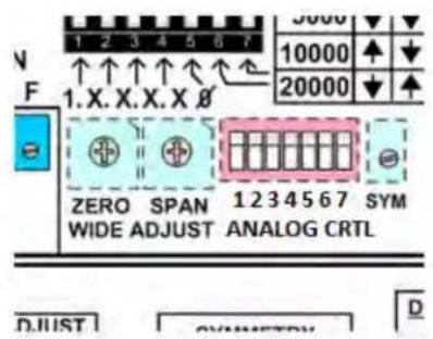
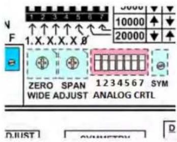
Wide Zero - 16 position switch to adjust wide zero-balance authority, approx. 13% /position Wide Span - 16 position switch to adjust wide range gain for 0.5 to 10 mV/V sensors
Display Span Adjustments
Used to adjust the digital readout of the 3770 meter, the user calibrates the analog output for a specific span value and then adjusts the readout for proper engineering units display. "OFF" position indicator defines the default position. i.e. 5.000 Vdc for the analog outputs equals to 5000 counts on the display.

Display Coarse Span - 16 position switch to adjust wide span / gain authority for the display Display Fine Span - 25 Turn potentiometer for fine span / gain control of display reading Display “OFF” – switch position “F” which disables the Adjustable Span feature of the display
3 Controls
Analog Control Settings
Front panel controls configure the Signal conditioner section for excitation level, mode of the analog output signal, low pass filter characteristics and shunt calibration being internal or external.
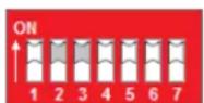
1 - 5 Vdc Output - UP sets the analog output FS to 5 Vdc, DOWN is 10 Vdc
2 -4 - 20 mA - UP sets the analog current output for 4-20 mA, DOWN is 4-12-20ma
3 - 20/200 Hz - UP selects 20 Hz filter. DOWN selects 200 Hz filter
4 - 20/2 Hz - UP selects 20 Hz filter. DOWN selects 2 Hz filter
5 - SHUNT Internal / External - UP selects the Internal Shunt Resistor - 59K, DOWN is External
6 - Excitation - UP selects 10 Vdc excitation to the sensor, DOWN selects 5 Vdc
7 - Not Used
With all switches in the UP position, the unit will have the following settings:
• 10 Vdc Excitation voltage
• The full scale analog output will be 5.000 Vdc
• The current output will be set for 4 ma = zero and 20 ma will = positive full scale
• The analog low pass filter will be set for 20 Hz
• Shunt calibration resistor will be set for the internal 59K Ohm resistor value
Note: The Excitation (switch 6) placement is used to select the mV/V input range of the unit. 5 Vdc setting will accept sensors from 5.0 to 10 mV/V. 10 Vdc setting will accept .5 to 5.0 mV/V sensors.
Analog Control Settings for Conditioner Configuration
| ↑ | Function | Down ↓ |
| 5 | 1 - VDC OUT | 10 |
| 4-20 | 2 - mA OUT | 4-12-20 |
| 20 Hz | 3 - FILTER | 200 Hz |
| 20 Hz | 4 - FILTER | 2 Hz |
| INT | 5 - SHUNT | EXT |
| 10 | 6 - EXC | 5 |
| 7 - N/A |
Analog Control Settings (red switch array)
The selection of the 7 front panel analog control settings will configure the signal conditioning section of the meter. The position of the switches will depend on the type of sensor, its parameters and the expected analog output signal levels along with the output signal's 3db roll-off response characteristics.
3 Controls
Analog Symmetry, + CAL, - CAL, TARE

SYM
Symmetry - Adjust the negative gain slope for symmetrical analog adjustment and display reading with reference to the positive span value. 20 Turn potentiometer, with approx. ± 2% full scale authority
+CAL
Positive Calibration - Activates the SHUNT Positive by switching in the external or internal shunt calibration resistor across the Cal Sense and + Sense leads of the bridge.
-CAL
Negative Calibration - Activates the SHUNT Negative by switching in the external or internal shunt calibration resistor across the Cal Sense and - Sense leads of the bridge.
TARE
TARE - Push / Push switch. When enabled, offsets the present sensor signal input to "Zero". When activated, a green LED light will illuminate. During activation process, LED will light Yellow. If disabled, or out of range, LED will be RED. TARE maybe remotely activated via rear J1 connections. Front panel TARE can be disabled via J1 Pin 5 connected to Logic Common, Pin 6. Maximum TARE capability is approx. 60% of full scale reading.
4. CALIBRATION
This section contains the instructions for calibrating the 3770. Included is a functional description of the instrument front-panel (see Page 1). To perform calibration, proceed as follows.
(a) Connect Sensor and Analog terminals as required. Connect and apply power to the unit. The front-panel digital display should light indicating the application of the AC input power. Allow 10 minutes of warm up for stabilization of transducer characteristics. Remove the front cover of the 3770 unit by removing the two small Phillips screws on the front panel. TARE should not be activated.
(b) Center the Zero and Fine Span potentiometers by rotating the potentiometers CW until you feel the "end stop" or by the number of turns accomplished (Coarse is 22 turn, Fine is 25 turn). Rotate the potentiometer back to the middle of their range (Coarse 11 turns, Fine 12-13 turns). This will establish the adjustments middle authority.
(c) Position the front panel switches to the desired settings for the application. Refer to Section 3 for details.
(d) Relax the sensor input to “zero” load and adjust the Wide Zero and Fine Zero controls until the meter reading is achieved at the point which will be the “zero” value reference.
(e) Once the Zero position has been established, apply a known load typically in the nominal working range of the sensor. With the load active and stabilized, adjust the Wide Span, Coarse Span and Fine Span controls until the display reading required is achieved.
(f) Return the sensor to the "Zero" position and re-adjust the Coarse Zero and Fine Zero controls for the desired reading or analog output of the unit. Repeat the Span (step e) adjustment as necessary to achieve the proper reading or analog output. Note that changes in Span (Gain) will affect Zero. Span and Zero re-adjustments may need to be repeated to obtain the desired reading. (Note that the 3770 meter also has independent display adjustment capability to where the digital display can be adjusted independently to the analog output signal of the unit so as to achieve proper analog output levels from the meter.)
(g) Once the Zero and the Gain (SPAN) adjustments have been accomplished, if needed - the user can adjust for Negative non-symmetrical value (as referenced by the positive SPAN value) by utilizing the front panel Symmetry control when the load is Negative. To accomplish this, apply a known negative load and adjust the symmetry control for the correct readout or analog output signal required. Note the Symmetry control has approx. ± 2 % full scale authority.
(h) Once completed, replace the front display lens cover to the original position and ensure proper shielding and grounding have been done to the meter. Minor calibration adjustment may be accomplished using the front panel potentiometer for zero and span.
Display Calibration The 3770 instrument display has separate adjustment controls that are independent of the analog output controls - allowing the user to alter the display reading to a value that is suited for the display while maximizing the analog output amplitude. In the standard - default switch position (as marked near the Coarse Display Span control), the display has a fixed full scale reading set by the display range switches of 5000, 10000 or 20000 counts. At these settings the full scale analog output signal will be 5 Vdc or 10 Vdc, as selected via the analog controls. To accomplish the display adjustment change, the user would first set the desired display range and decimal location using the display dip switches, adjust the analog output to the desired level and then adjust the display Coarse then Fine span controls for the required digital readout.
4. CALIBRATION – Shunt Calibration
This section contains the instructions for calibrating the 3770 using the Shunt calibration method.
(a) Connect Power, Sensor and Analog terminals as required. Apply power. The front-panel digital display should light indicating the application of the AC input power. Allow 10 minutes of warm up for stabilization of transducer characteristics. Remove the front panel cover of the 3770 unit which is held in place by the two small Phillip head screws.
Note: The 3770 unit has an internal 59K Shunt resistor installed within the unit. If a different resistor value is to be used to correspond to the transducer's calibration sheet; install the resistor on the rear J1 terminals provided and place the Analog Control Switch 5 to External. Shunt calibration will only activate if the CAL Sense line is connected to the + or - Signal lines on the transducer input connector J2.
For transducers with an internally installed shunt resistor: 1.) Cal Sense should be attached to the transducer's shunt activation connector pin; 2.) External Shunt selected on the Analog Controls; 3.) A shorting wire is to be installed in place of the External Shunt resistor terminals on the rear of the unit.
(b) Center the Zero and Span potentiometers as needed by rotating the potentiometers fully CW (Coarse is 22 turns, Fine is 25 turns), then reverse direction - CCW (Coarse 11 turns and Fine 13 turns) to obtain mid-authority of the controls. Typically this is done on initial calibration. When recalibrating for minor adjustments this may not be required.
(c) With mechanical Zero or Balance established at the transducer (transducer "relaxed"); Adjust Wide Zero then Coarse Zero and then Fine Zero for the Zero position reading on the display or the desired analog output signal. Display can be adjusted independently to the analog signal.
(d) Depress and hold the + CAL button while adjusting the Wide Span, Coarse Span and Fine Span controls, as needed, for precise engineering units reading on the display as determined by the sensor's calibration sheet or other reference data (see Equivalent Input shunt calculation below).
(e) Repeat Steps (d) and (e) to obtain proper measurement readings since the Gain - Span controls will affect the Zero amplification of the input signal.
(f) Once completed, if the sensor is going to be utilized in the Negative or CCW mode, depress and hold the - CAL button and adjust the Symmetry control for a proper symmetrical reading of the shunt input as noted on the sensor's calibration data sheet. Note the Symmetry control affects the Negative Span for approx. ± 2% of full scale adjustment control.
(g) Release the Cal button and adjust Zero as needed. Re-install the front panel to the instrument. Minor adjustments and controls are assessable via the front of the unit.
4. CALIBRATION (cont.) – Shunt Calibration Equivalent Calculation
If dead weight calibration is not practical and the transducer calibration data is unknown, the Equivalent Input value for the factory-installed calibration resistor can be approximated as follows, assuming that the mv/v sensitivity rating of the transducer and the bridge resistance is known.
X = 2 5 0 0 0 xRb/KxRc
Where X = Equivalent Input, % of full scale Rb = bridge resistance, ohms K = transducer sensitivity, mv/v full scale Rc = calibration resistance, ohms (59 K installed)
Sample Calculation: Assume that K = 3.000 mv/v for a 5000-pound load cell (full scale) with a bridge resistance of 350 ohms and using the internal 59K Ohm shunt resistor.
25000 × 350/59000 × 3 = 49.44 % of full scale = 2472 pounds
When + CAL is depressed, input sensor is at zero, display is on the 5000 range, adjust the readout for 2472
Display Calibration The 3770 instrument display has separate adjustment controls that are independent of the analog controls which allow the user to alter the display reading to a value that is suited for the engineering units display reading required. The additional span controls allow the user the flexibility to adjust the display reading as referenced to the analog signal or referenced to the defaulted front panel display dip switches. In a standard – default “OFF” switch position of the Coarse Span control, the display has a full scale reading set by the display range switches of 5000, 10000 or 20000 counts. At the selected reading the full scale analog output signal will be 5 VDC or 10 VDC, as selected by the Analog Controls of the unit. To accomplish the display adjustment change, the user would first set the desired display range and decimal location using the display dip switches, adjust - calibrate the analog output to the desired amplitude level and then adjust the display Coarse and Fine span controls for the required digital readout.
Tech Tip: The inability to balance correctly where the unit output reads totally off scale and the zero controls have no authority can very likely be the result of a damaged or defective transducer or cable. This possibility can be confirmed (or eliminated) by substituting a transducer and cable known to be in good condition or by simulating a balanced transducer, using either a commercially available transducer simulator or the simple star bridge arrangement shown below. The star bridge simulates a conventional four-arm bridge in an exact condition of balance. To construct a star bridge connect four resistors as shown; use 180-ohm resistors to approximate a 350-ohm bridge.
Neither the resistor values nor temperature characteristics are critical. Solder two excitation resistors together, and then solder the two Signal resistors together. Next, connect the two junctions together using a separate wire as shown. There is a good reason for this method of construction, and it should be followed. Connect the substitute or simulated transducer to the module I/O connector using a short 4-wire cable configuration as shown in Figure 4. Attempt to balance the substitute or simulated transducer. If conditions now appear to be normal, the transducer or cable is at fault. If the previous difficulties persist, the meter is at fault.

Tech Tip on use of wide range settings for the DC Strain Gage Conditioner
Due to multiple amplifier stages within the 3770 instrument, attention to the proper gain setting and understanding of the sensor inputs should be reviewed to produce a linear-amplified analog output signal and display reading.
The wide span – gain control (as shown in the front panel diagram) has 16 positions to amplify the incoming signal by incremental steps. Each step is positioned so the Coarse and Fine Span potentiometer controls overlap each step to provide a continuous linear gain of the signal from 0.5 mV/V to 10.00 mV/V full scale. Below is a table of each wide gain steps, indicating the nominal low and high input signal range per position – full scale in mV/V to the meter.
Note: When using 5 V excitation, increase the table values by a factor of 2.
| Wide Span Position | SPAN-Low mV / V | SPAN-High mV / V |
| 0 | 3.90 | 5.80 |
| 1 | 3.30 | 4.90 |
| 2 | 2.90 | 4.20 |
| 3 | 2.50 | 3.60 |
| 4 | 2.10 | 3.10 |
| 5 | 1.80 | 2.70 |
| 6 | 1.50 | 2.30 |
| 7 | 1.30 | 1.90 |
| 8 | 1.10 | 1.70 |
| 9 | 1.00 | 1.40 |
| A | 0.84 | 1.20 |
| B | 0.72 | 1.00 |
| C | 0.62 | 0.92 |
| D | 0.53 | 0.80 |
| E | 0.45 | 0.65 |
| F | 0.38 | 0.58 |

DC Strain Gage Sensors sensor:
DC Strain Gage Sensors will typically specify their electrical sensitivity in mV/V for traditional foil gage transducers or in mV full scale for semiconductor type sensors; either type will function with the 3770 unit as dictated by the excitation voltage needed along with the full scale output of the sensor. The 3770 has selectable excitation of 5 and 10 Vdc and a maximum specified input of 50.0 mV (with 20% over-range) into the meter. As a reference, the above table can be used as a guide to determine the working full scale range of the transducer during calibration and the proper position of the Wide Span control. Note that additional gain or less gain can be accomplished as needed if an expanded or reduced area of the sensor measurement level is required.
5. FUSE REPLACEMENT
Should you suspect a blown fuse proceed as follows.
WARNING
Installation, operation and maintenance of this instrument must be performed by qualified personnel only. The National Electrical Code defines a qualified person as “one who has the skills and knowledge related to the construction and operation of the electrical equipment and installations, and who has received safety training on the hazards involved.”
a) Disconnect al | power sources and cables connected to the instrument before servicing the instrument.
b) On the rear panel remove the (2) clamp slide retaining screws and remove the clamp slides from both sides of the instrument. Next remove the (4) corner screws that retain the rear panel to gain access to the instrument.
c) Open the rear panel and replace the fuse(s) as required, replace only with same type T Slow Blow, 1A, 250V (Littelfuse 218001.HXP, 1 A). The fuseholder wire conductors are appropriately labeled "L" for Line and "N" for Neutral on both halves of each of the fuseholder wires. When reassembling the fuseholder(s) make sure "L" and "L" are connected together and "N" and "N" labeled wires are connected together properly.
d) Mate the rear panel to the enclosure and replace the clamp slides back in position and secure the clamp slides with the (2) screws previously removed from the instrument. Next, replace the (4) corner screws to secure the rear panel and ensure that all screws have been adequately tightened.
e) Power ON the instrument with the appropriate power cord and verify the instrument is functioning properly before reconnecting the instrument to your installation.
WARNING
For continued protection against risk of fire or shock replace only with the same type and rating of fuse.
ADVERTENCIA
Do not replace fuse again if failure is repeated. Repeated failure indicates a defective condition that will not clear with replacement of the fuse. Refer condition to a qualified technician.
ADVERTENCIA
Product Warranty and Repair
Daytronic Corporation warrants its products to be free from defects in material and workmanship, under normal and proper use in accordance with our instructions, for the period of time specified below. Our liability under such warranty or in connection with any other claim relating to the products shall be limited to, at our option, the repair or replacement of any products or parts or components thereof which are returned to us freight prepaid and which are defective in material or workmanship or the refund of the purchase price to the Buyer.
ANY PRODUCT FOUND TO BE DAMAGED THROUGH CUSTOMER NEGLIGENCE OR MISUSE MAY BE EXCLUDED FROM ANY AND ALL POLICIES CONTAINED IN THIS DOCUMENT.
ALL EQUIPMENT TO BE REPAIRED OR REPLACED UNDER WARRANTY MUST BE RETURNED TO THE FACTORY. Before returning a product or products for any reason, the customer must call Daytronic Customer Support Services at (937) 866-3300 to request a RETURN MATERIAL AUTHORIZATION (RMA). Once the customer has provided the necessary information and has been assigned a specific RMA, the product(s) in question may be returned to Daytronic by shipping it
Daytronic Corp., 1000 New Durham Road, Edison, New Jersey 08818 Daytronic Customer Service: 1-800-668-4745 service@daytronic.com

DAYTRONIC
Daytronic Corporation Dayton OH USA www.Daytronic.com
3700 SERIES
"P" Option
ANALOG PEAK CAPTURE
INSTRUCTION MANUAL

3700
Instrument Series
3700 SERIES
"P" Option
ANALOG PEAK CAPTURE
INSTRUCTION MANUAL
1. General Description
The "P" option of the 3700 Series Meter is an added function card which provides the ability of the meter to capture and hold + Peak, -Peak, Max-Min or TIR value that originates from the base 3700 instrument. Any 3700 (except Horsepower 3741) can accommodate the "P" option. Peak Mode signals are captured in real-time analog capacitive memory and are available for display and analog output monitoring. Only one of the following four separate modes can be configured for the Peak Capture operation.
PEAK MODE
Description
| + PEAK | Captures and holds the most positive measurement signal in the positive quadrant |
| - PEAK | Captures and holds the most negative measurement signal in the negative quadrant |
| MAX + MIN | Captures and holds the sum of the MAXIMUM and MINIMUM signal values |
| TIR | Captures and holds the difference in the Positive and Negative Peak values only in the positive signal quadrant of the measurement |
Peak functions are configured using the rear panel dip switches and connector terminals as illustrated in figure 1. Dip switch configuration enables various features - front panel TARE push button function, Peak Mode selection, Analog signal source of either the Fast or Select signal from the main 3700 unit, and Threshold detection levels for Have Peak Capture and logic triggering.
Rear panel connector terminals are used for remote control using logic switches or PLC type I/O control to activate / reset meter functions. Logic I/O signals for Peak Arming and Clearing (tracking) of the Peak capture value, switching the display from Live to Peak, Have Peak output and front panel enabling of the TARE switch for Peak/Reset of the captured value. The resultant analog captured signal is available via the "PEAK" connector terminal as noted in section 3 - Connections.
Fig. 1 3700P Peak Capture Option - Rear Panel Layout
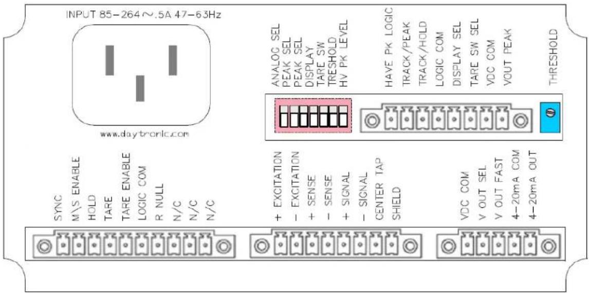
Threshold adjustment potentiometer located to the right of the Peak I/O connection is used for level adjustment of the "Have Peak" detection around the input signal's Zero level. This adjustment is used to prevent low-level signal content from triggering an inadvertent "Peak Hold". Adjustment level is viewable from the front panel (SW 6 Down) and is adjustable from 1 to 8% of full scale.
2. DIP Switch Configuration
Located on the rear panel above the main board connections, the 7 position dip switch configures the PEAK functions of the meter. The Default position of the switch is in the UP (ON) position as noted in the table below.

Viewed from the rear. Switch "Rocker" in the UP position, is ON and considered the Default function as described below.
Default Position - Switches are all "ON" (UP)
| Analog Signal Source | FAST analog signal response from main 3700 |
| PEAK Mode | + PEAK Mode of operation, see Fig 4 |
| Display Reading | LIVE measurement signal is displayed |
| Front Panel TARE | Normal TARE switch operation |
| Peak Capture | 1% of Full Scale between Live and Peak level detection |
Switch #
Function
1 ANALOG SIGNAL SOURCE
Selects FAST or SELECTED analog signal source from the main 3700 unit.
2 PEAK MODE
Used with switch 3 for PEAK Mode function - +PEAK, -PEAK, MAX+MIN, TIR
3 PEAK MODE
Used with switch 2 for PEAK Mode function - +PEAK, -PEAK, MAX+MIN, TIR
4 DISPLAY
Selects LIVE Reading or PEAK Reading for the front panel display
5 FRONT PANEL TARE SWITCH
Selects the front panel TARE switch for TARE or PEAK/RESET function
6 PEAK THRESHOLD DISPLAY ADJUST
7 HAVE PEAK DETECT
Analog delta detection level for PEAK capture detection - (Backout level 1% or 0.1% Full Scale)
Switches the front panel display to adjust the level for HAVE PEAK THRESHOLD (Switch 4 to LIVE)
Switch # Default - UP (ON)
DOWN (OFF)
1 FAST Analog Signal
SELECT Analog Signal (low pass filtered selected) per main analog controls of the 3700 base unit.
2 + PEAK - UP
- PEAK - DOWN
MAX + MIN - UP
TIR - DOWN
3 + PEAK - UP
- PEAK - UP
MAX + MIN - DOWN
TIR - DOWN
+ PEAK
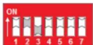
MAX + MIN
* see note
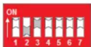
- PEAK

TIR
* see note
4 LIVE display
PEAK Display
5 Front Panel TARE - normal operation
Front Panel TARE used for PEAK / RESET
6 Standard Run-Time Operation
Selects THRESHOLD display adjustment
7 1% Full Scale Peak "Backout" Detect
0.1% Full Scale Peak "Backout" Detect
* Note: When in the Max-Min or TIR mode, the signal may over-range due to the sum of the +/- Peak captured signals being greater than full scale. Nominal capture level should be in the area of 50% full scale or less.
Functional Block Diagram of the PEAK switch settings
![graph TD A["3700 Main Unit's Signal conditioned Analog Signal (0 - ±5 or ±10 Vdc)"] --> B["FAST"] B --> C["Switch #1"] C --> D["MODE Selection Switch #2 & 3"] D --> E["PEAK Option"] E --> F["TARE Switch"] F --> G["BACKOUT Level for Peak Detect"] G --> H["Threshold Potentiometer"] H --> I["LIVE Value…](/content/2026/06/1249001/images/1edfcd72b2ad896f754269256951feefc6b71cc2cd27b9f7a1768ba2a1723e9f.jpg)
3. PEAK Interface I/O Connections
Pin assignments for the 3700P board's 8-pin I/O connector (shown in Fig. 1) functional description
Pin Number
Function
| 1 | Output | HAVE PEAKOutput Logic Signal, indicates a Peak has been detected. |
| 2 | Input | TRACK or PEAKInput Logic Signal to Clear (Track) or to Arm for a Peak capture function |
| 3 | Input | TRACK or HOLDInput Logic Signal to HOLD the Peak reading. Must be in Track Mode to clear Peak (Pin 2 false, not grounded) |
| 4 | LOGIC COMMONCommon for Logic signal activation | |
| 5 | Input | DISPLAY - LIVE or PEAK ReadingInput Logic Signal to select Live Reading or Peak Reading for front panel display |
| 6 | Input | FRONT PANEL TARE for Display of PEAK or LIVE signalInput Logic Signal to use the front panel TARE switch for PEAK or LIVE display reading |
| 7 | ANALOG COMMONCommon for analog signal reference | |
| 8 | Output | PEAK ANALOG SIGNALAnalog Output - Holds PEAK analog value when in PEAK mode; follows analog input continuously when in TRACK mode. Full scale level is determined by the 3700 main units output selection - +/- 5V or +/- 10V. |
4. Setup conditions for the "P" option and TARE switch operation
When the "P" option is installed - the front panel "TARE" Push/Push switch can be configured to operate in three separate function modes for local operation depending on the DIP switch selection and/or logic inputs selected.
Function Mode of the TARE switch
- Standard "TARE" capability for normal operation - Will TARE the input measurement of the analog signal and the display to "Zero". LED will light GREEN when active and within normal offset TARE range. Remote TARE via the rear connector functions in a similar fashion.
- PEAK capture or Track mode - When the TARE switch is depressed, the meter will be in "track" mode following the input signal amplitude. When the TARE switch is released (outward position) the meter is armed and ready to capture the Peak as configured by Dip Switch 2 & 3.
- Used for local control of the Front Panel display -TARE button depressed will display the PEAK reading. Outward position of the switch will display the "Live" reading. Switch action will not perform a Peak reset operation, this must be done via connection terminal 2's activation for TRACK - PEAK.
Note: If the Peak option is installed in a Model 3740 Frequency conditioner, the TARE mode switch functionality is only accessible via the rear logic connector input
Function Mode Setup and configuration details
1. Standard TARE operation Default condition
- Dip Switch 4 & 5 UP, Peak Input connection Pin 5 and 6 are not used. Remote connections for remote TARE are available. Refer to the main meter manual for details.
2. Front Panel Peak Reset Function
- Dip Switch 4 & 5 DOWN or Switch 4 DOWN and Input connection Pin 5 Grounded (True). Input connection Pin 6 can not be used. Remote TARE function operates via main meter connector.
3. Local Display of Live or Peak Reading
- Dip Switch 4 & 5 UP, Input connection Pin 5 not utilized, Pin 6 is grounded (True). Remote TARE function operates via main meter connector.
4. Interface I/O Connections
Interface Connector Operation
The 8 pin rear connector provides remote access to the Peak operational parameters. All logic I/O are negative true signals - logic common when active or true.
Functional diagrams of the logic for enabling PEAK functions are shown in Fig. 3 thru 6. Typically usage of the I/O connections are for remote control of the application sequence to "handshake" with a controller for proper operation of the measurement capture and resetting process of the PEAK Mode function.
Display Source and Front Panel TARE button mode of operationl are available to provide remote control enabling of the local operation of the 3700 Peak features as configured by the 7 postion dip switch settings as described in section 2.
Analog Output of the PEAK Mode function is available. The Analog level is dependent on the configuration of the main analog controls of the 3700 unit... +/- 5 V or +/- 10 Vdc full scale level. Analog output, when in the HOLD or PEAK capture mode, is accomplished using capacitive memory and will have a "leak" rate of 1 millivolt per 10 seconds.
Fig. 2
Track/PEAK Via External Command (Switch, Open Collector Transistor, or TTL Logic)
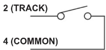

![graph TD A["2 (TRACK)"] --> B["TTL"] C["4 (COMMON)"] --> B["TTL"]](/content/2026/06/1249001/images/345aaf5f06e5535e2146f8f81e6076484ccbfcb39be35559680b7d0fb6f94e30.jpg)
+ PEAK Mode - captures and holds the most positive signal amplitude of the measurement within the positive quadrant of the signal. Switch 2 UP - Switch 3 UP
Fig 3

- PEAK Mode - captures and holds the most negative signal amplitude of the measurement within the negative quadrant of the signal. Switch 2 DOWN - Switch 3 UP
Fig 4

MAX + MIN Mode - captures and holds the most positive signal and the most negative signal amplitude in the positive and negative quadrants of the measurement resulting in an absolute analog output signal. Switch 2 UP - Switch 3 DOWN
Fig 5

Note: When in Max-Min mode the analog signal may overrange due to the summing of the + Peak and - Peak captured signal.
TIR Mode - captures and holds the most positive signal and the most negative signal amplitude in the positive quadrant of the measurement. Switch 2 DOWN - Switch 3 DOWN
Fig 6
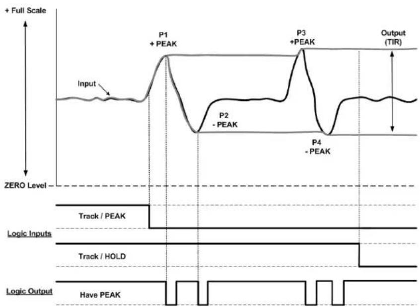
Threshold Level Adjust and Have Peak Detection (Backout)
Switch 6 - PEAK THRESHOLD DISPLAY ADJUST on the rear panel dip switch: When in the DOWN position, will switch the front panel display to provide level adjustment of the Threshold Potentiometer to provide a "No Peak Zone" around the Zero level. This adjustment is used to eliminate false Peak Captures around the zero measurement level as shown in the gray area of the Fig. 7 below. Adjustment is from 1 to 8% of the full scale reading.
Switch 7 - HAVE PEAK DETECT (Backout): Selects the amplitude of the "delta" between the live signal and the detection of a Peak value which has occurred. Sometimes referred to as "Backout" as shown in the circle graphics below. This level sets the recognition level of when a PEAK has occurred. Level is 0.1% (DOWN) or 1.0% (UP) of full scale. Setting will depend on signal dynamic content and the sharpness of the peak event. Placement of Switch 1 (Analog Signal Source) will also have an affect on this setting due to the analog filtering response of the FAST or the SELECTED analog signal as determined by the response time of the FAST signal for the 3700 Model or the Select Analog Filter per the Analog Control switches located on the main 3700 unit.....switch 3 & 4.
Fig 7
![graph TD A["Input"] --> B["Threshold Adjustment – Peak Defeat Zone (1-8% FS)"] B --> C["Output (+ PEAK)"] D["+ Full Scale"] --> E["Switch 7 Backout Level"] E --> F["Have PEAK Detect"] F --> G["0.1 or 1% Full Scale (Switch 7)"] G --> H["Output"] I["ZERO Level"] --> J["Switch 6 for display adjust leve…](/content/2026/06/1249001/images/7b968a096526824827936d58a0ca35cac28d3eec31db9e9cbff796acb06a12d3.jpg)
Quick Set-up operation
1. Determine the Peak Mode required
Configure switch settings 2 and 3 for the proper function.
2. Select FAST or SELECT signal source
Configure switch 1 - FAST will be the highest dynamic capture. SELECT will reflect the low pass filter selection on the main 3700 Analog Controls.
3. Select the Front Panel Operation of the TARE Switch
Configure switch 5 - Normal operation of the TARE switch to provide "zero-ing" of the analog signal or to use the TARE switch as a front panel PEAK -TRACK "push-push" operation to place the 3700 unit is PEAK capture Mode or Reset the PEAK that has been held resulting in the display and analog output signal tracking the live input. Push IN - PEAK. Push OUT - TRACK.
4. Select the Operation of the Display
Switch 4 - Meter display can be configured for LIVE display or the PEAK capture value. If the unit is a "stand-alone" meter with the local operator providing the Peak Reset, as mentioned in step 3, then Switch 4 should be DOWN for PEAK display operation. Remote control of the display can also be done via the I/O connections with an external switch or controller providing the Display control function.
5. Determine how much "threshold" level is needed for your application
Switch 6 will display the threshold value (1 to 8%) for a bi-polar "no peak detection zone" around the Zero measurement level. This adjustment is normally in the 5% area, but can be adjusted depending on the application and how much PEAK defeat / rejection is needed. When finished with the potentiometer adjustment, return Switch 6 to the UP position.
6. Determine the need for remote control of your application
Refer to the Connector I/O interface in section 3 for setup functions of the 8 positon terminal connector. Switch function 4 and 5 can be remotely controlled. All other switch settings are typically configured during initial setup of the 3700 unit and will not be changed.
Peak Capture Response
The Peak Capture of the analog signal is performed using “capacitive” memory. This technique is very repeatable and does not involve digital sampling errors. It does, however, result in a millivolt/second “leak rate” after the initial “capture” which varies depending on the Peak Capture cycle rate, amplitude of the analog signal and the wave shape of the signal being monitored. Below are the leak rate values as expressed in percent of full scale using defined parameters of a single square wave pulse input of 1, 10 and 100 milliseconds in duration at the full scale value of 5.000 V.
Square Wave Full Scale Error after Peak was captured
| Pulse Width | 10 mS | 100 mS | 1 Sec | |
| 1 mS | 0.10% | 0.15% | 0.20% | |
| 10 mS | 0.05% | 0.07% | 0.10% | |
| 100 mS | 0.02% | 0.02% | 0.06% |
Typical Leak rate graph with a 100 mS pulse example

Page left blank
Copyright © 2015, Daytronic Corporation. All rights reserved.
No part of this document may be reprinted, reproduced, or used in any form or by any electronic, mechanical, or other means, including photocopying and recording, or in any information storage and retrieval system, without permission in writing from Daytronic Corporation. All specifications are subject to change without notice.

DAYTRONIC
Daytronic Corporation
- ADVERTENCIA
- STANDARD ACCESSORIES
- 1 GENERAL DESCRIPTION AND SPECIFICATIONS
- 3770 SPECIFICATIONS
- AMPLIFIER
- A PANEL MOUNTING
- 2 CONNECTIONS
- J1 - SHUNT ACTIVATION CONNECTIONS
- J1 LOGIC CONTROLS
- WARNING
- J3 - ANALOG OUTPUT CONNECTIONS
- 3 CONTROLS
- DISPLAY RANGE AND DECIMAL POINT SELECTION
- ANALOG ZERO AND SPAN ADJUSTMENTS
- ANALOG WIDE GAIN AND ZERO CONTROLS
- DISPLAY SPAN ADJUSTMENTS
- ANALOG CONTROL SETTINGS
- ANALOG CONTROL SETTINGS FOR CONDITIONER CONFIGURATION
- SYM
- CAL
- TARE
- CALIBRATION
- CALIBRATION – SHUNT CALIBRATION
- CALIBRATION (CONT.) – SHUNT CALIBRATION EQUIVALENT CALCULATION
- TECH TIP ON USE OF WIDE RANGE SETTINGS FOR THE DC STRAIN GAGE CONDITIONER
- DC STRAIN GAGE SENSORS SENSOR
- FUSE REPLACEMENT
- PRODUCT WARRANTY AND REPAIR
- 3700 SERIES
- P" OPTION
- ANALOG PEAK CAPTURE
- INSTRUCTION MANUAL
- GENERAL DESCRIPTION
- DIP SWITCH CONFIGURATION
- DEFAULT POSITION - SWITCHES ARE ALL "ON" (UP)
- SWITCH
- FUNCTION
- SWITCH # DEFAULT - UP (ON)
- DOWN (OFF)
- PEAK INTERFACE I/O CONNECTIONS
- SETUP CONDITIONS FOR THE "P" OPTION AND TARE SWITCH OPERATION
- FUNCTION MODE OF THE TARE SWITCH
- FUNCTION MODE SETUP AND CONFIGURATION DETAILS
- STANDARD TARE OPERATION DEFAULT CONDITION
- FRONT PANEL PEAK RESET FUNCTION
- LOCAL DISPLAY OF LIVE OR PEAK READING
- INTERFACE I/O CONNECTIONS
- INTERFACE CONNECTOR OPERATION
- THRESHOLD LEVEL ADJUST AND HAVE PEAK DETECTION (BACKOUT)
- QUICK SET-UP OPERATION
- DETERMINE THE PEAK MODE REQUIRED
- SELECT FAST OR SELECT SIGNAL SOURCE
- SELECT THE FRONT PANEL OPERATION OF THE TARE SWITCH
- SELECT THE OPERATION OF THE DISPLAY
- DETERMINE HOW MUCH "THRESHOLD" LEVEL IS NEEDED FOR YOUR APPLICATION
- DETERMINE THE NEED FOR REMOTE CONTROL OF YOUR APPLICATION
- PEAK CAPTURE RESPONSE
- PAGE LEFT BLANK
- COPYRIGHT © 2015, DAYTRONIC CORPORATION. ALL RIGHTS RESERVED
- DAYTRONIC
Brand : Daytronic
Model : 3770DCP
Category : Measurement