5T70V - Measurement Daytronic - Free user manual and instructions
Find the device manual for free 5T70V Daytronic in PDF.

User questions about 5T70V Daytronic
0 question about this device. Answer the ones you know or ask your own.
Ask a new question about this device
Download the instructions for your Measurement in PDF format for free! Find your manual 5T70V - Daytronic and take your electronic device back in hand. On this page are published all the documents necessary for the use of your device. 5T70V by Daytronic.
USER MANUAL 5T70V Daytronic
with Class 2 IEEE-1451.4 load capability
INSTRUCTION MANUAL

text_image
Circuit Range: 0.5 to 16.0 mW Exchanger: 2.5 or 50 VDC Receiving Output Data: 510VDC Q087 Module Adapters POWER/DRAWTH ANAL Power (A) / VCC 20 Voltage Power (A) / VCC 20 RDC DC Power Control PLUMBING ACDC Power Control 5T70V DC Drive High-Conditioner DRYTRONIC RDC R2-232 RMC RL-232 RPM RL-232 RPNRL RUNUT - RUNUT - RUNUT - RUNUT - RUNUT - RUNUT - RUNUT - RUNUT - RUNUT - RUNUT - RUNUT - RUNUT - RUNUT - RUNUT - RUNUT - RUNUT - RUNUT - RUNUT - RUNUT - RUNUT - RUNUT - RUNUT - RUNUT - RUNUT - RUNUT - RUNUT - RUNUT - RUNUT - RUNUT - RUNUT - RUNUT - RUNUT - RUNUT - RUNUT - RUNUT - RUNUT - RUNUT - RUNUT - RUNUT - RUN UT - RUNUT - RUN UT - RUNUT - RUN UT - RUNUT - RUN UT - RUNUT - RUN UT - RUNUT - RUN UT - RUNUT - RUN UT - RUNUT - RUN UT - RUNUT - RUN UT - RUNUT - RUN UT - RUNUT - RUN UT - RUNUT - RUN UT - RUNUT - RUN UT - RUNUT - RUN UT - RUNUT - RUN UT - RUNUT - RUN UT - RUNUT - RUN UT - RUNUT -VERSION SB.1.0
MANUAL PART No. 92378.00
Copyright ©2019, Daytronic Corporation. All rights reserved.
No part of this document may be reprinted, reproduced, or used in any form or by any electronic, mechanical, or other means, including photocopying and recording, or in any information storage and retrieval system, without permission in writing from Daytronic Corporation.
All specifications are subject to change without notice.
Daytronic Corporation
Dayton, OH • (800)668-4745
www.daytronic.com
TABLE OF CONTENTS
1 INTRODUCTION
1.A General Description and Specifications 5T70(V) - 1.1
1.B Installing and Running the 5D Configurator Software 5T70(V) - 1.4
2 CONNECTIONS
2.A Introduction - Overview of terminal Connections.... 5T70(V) - 2.1
2.B Power and Ground Connections 5T70(V) - 2.2
2.c Serial Communications Connections 5T70(V) - 2.3
2.D Transducer Connections 5T70(V) - 2.4
2.E Analog Output Connections 5T70(V)-2.5
2.F Logic Input Connections 5T70(V) - 2.6
2.G Transducer Electronic Data Sheet Operation 5T70(V) - 2.7
3 CONFIGURATION AND CALIBRATION
3.A Using the 5DConfigurator 5T70(V) - 3.1
3.B Summary of Configurator Menus 5T70(V) - 3.2
3.c Overview of the Configuration Process 5T70(V) - 3.3
3.D 5T70(V) Calibration 5T70(V)-3.5
4 OPERATING CONSIDERATIONS
4.A Sending a Command to the 5T70(V) 5T70(V) - 4.1
4.B Applying a Positive or Negative Shunt to the 5T70(V) 5T70(V)-4.1
5 TROUBLESHOOTING
5.A Interpreting the Status Indicator Light 5T70(V) - 5.1
5.B Interpreting the Module Diagnostic Code 5T70(V) - 5.1
APPENDIX SUMMARY OF 5T70(V)
A.1 Command and Response Syntax 5T70(V) - A.1
B.1 Absolute Calibration Calculations 5T70(V) - B.1
C.1 Transducer Electronic Data Sheet Theory of Operation 5T70(V) - C.1
D.1 Verification of Normal Operation 5T70(V) - D.1
E.1 Tested Load Manf. w/wiring diagram 5T70(V) - E.1
ILLUSTRATIONS
Fig. 1 5T Dimensions .... 5T70(V) - 1.2
Fig. 3 5T Power, Configuration, Logic, and Analog Output Connections ..... 5T70(V) - 2.1
Fig. 4 5T 24 VDC Power Connections 5T70(V) - 2.3
Fig. 5 5T Computer Communications Connections 5T70(V) - 2.3
Fig. 6 ModEOV) Transducer Connections
Fig. 6.a 4-Wire Strain Gage Cabling (under 20 ft. in length) 5T70(V) - 2.4
Fig. 6.b 8-Wire Strain Gage Cabling (20 ft. or longer) 5T70(V)-2.4
Fig. 7 5T Analog Output Connections 5T70(V) - 2.5
Fig. 8 Model 5T70Input Connections.... 5T70(V) - 2.7
Fig. 9 Transducer Electronic Data Sheet Connections.... 5T70(V) - 2.8
Fig. 10 Software Configuration Menus fo the Model 5T70(V) 5T70(V) - 3.2
Fig. 11 Configuration and Calibration Process for the 5T70(V) 5T70(V) - 3.4
Fig. 12 Star Bridge Connections for Troubleshooting 5T70(V) - D.1
TABLES
Table 1 Model5T70(V) Terminal Connections 5T70(V) - 2.1
Table 2 "Practical" 5T70(V) Range (RNG) Settings 5T70(V) - B.1
1. INTRODUCTION
1.A GENERAL DESCRIPTION AND SPECIFICATIONS
The Model 5T70(V) is a single-channel DIN Mount instrument based on the Daytronic Model 5D70 technology with the added features of a USB interface and a Transducer Electronic Data Sheet input per IEEE-1451.4 (TEDs) Class 2 MMI. User may configure or re-configure the 5T70(V) via the computer interface. Using a TEDs enabled Wheatstone mv/V stain gage bridge sensor is a quick, reliable means to calibrate the conditioner with the sensor to measure force, pressure, torque and other DC strain gage related measurements. The Model 5T70(V) has an extremely wide mV/V input range with selectable gain, zero and analog filter settings - making it adaptable to any user's sensor application that requires stable, repeatable and noise free analog signals for control or data acquisition.
The 5T70 delivers filtered analog outputs of ±5 VDC, while the 5T70V produces ±10 VDC. For both models, advanced analog design directly addresses the problem of measurement inaccuracy in industrial environments of high electromechanical noise. Exceptional signal stability and accuracy over a remarkably wide range of sensor inputs are achieved through
• remotely sensed excitation, user-selectable
• chopper-stabilized low-drift amplification
• configurable low-pass active filtering
• "absolute" software-based calibration
• effective signal isolation & ESD protection
Each compact 5T70(V) module is a self-contained, easily configurable instrument. with screw-terminal connectors for easy installation and I/O field wiring, it can be used as an individual - effective, economical front-end solution. Connecting directly to its source strain gage sensor via simple pinout, the module powers, conditions, isolates, filters, and scales its sensor's analog signal to a standardized ±5-V or ±10-V level, making it usable as input to a PC, PLC, or other device for further processing, display, recording, etc. High output accuracy over a wide temperature range guarantees repeatable sensor signal integrity.
The Model 5T70(V) overcomes errors that traditionally plague the strain-gage measurement process. For steady indication and smooth, dependable control action, the 5T70(V) can provide a true average value of the measured variable, even in the face of substantial dynamic content. Two high-level, noise-free analog out-puts are provided. Both are identical, however they can have separate analog filter settings for dynamic and non-dynamic acquisition.
Both models feature
- Powerful low-pass active filtering, independently selectable for each output, for removal of unwanted high-frequency measurement-signal components and the elimination of aliasing errors, if the module's output is subsequently sampled
- Selectable excitation using remote sensing of bridge voltage and slaved to an extremely stable reference voltage
- Input impedance more than 10,000 MΩ is presented to signal leads to eliminate cable resistance as a source of error (allowable cable length has virtually no practical limits)
- High noise rejection, eliminating errors from common-mode pickup and ground-loop coupling, with 1500 VAC isolation between input and output terminals and between I/O and power supply / communications terminals
With the TEDs enabled device - calibration can be accomplished using:
1) The sensor's manufacture data sheet which is contained in the one wire chip onboard the sensor.
2) Using the computer interface port to enter user defined parameters (absolute calibration).
3) Using the computer interface port to calibrate using the traditional "dead weight" method.
4) Using the computer interface port using the shunt calibration method in place of the "dead weight" input.
The 5T70(V) ensures high accuracies, without elaborate trial and error procedures. Thus, to calibrate a 5T70(V), no "dead-weighting" is required; as explained in Section 3.D, you need only use the TEDs upload process or the configuration software provided with the unit to change or specify the desired relationship between the module's measured engineering units and its ±5-VDC or ±10-VDC output, given the full-scale input range for which it is currently set and the strain gage transducer's known full-scale rating and sensitivity. A zero-off set term may also be entered, expressed either in engineering units or millivolts.
Conventional TWO-POINT (DEADWEIGHT) CALIBRATION may be applied, if desired, to improve on the TEDs loaded data or the "absolute" calculations, when there are at least two independently and accurately known calibration points ("ZERO" and "SPAN"). Activation of a user-supplied shunt calibration resistor is provided (for either a positive or negative upscale reading) for use in the two-point method, if desired. Internal symmetry trimming is also available for negative-domain slope adjustments of up to ±2% of full scale.
1. INTRODUCTION
Guaranteed "absolute" calibration accuracies for a properly configured 5T70(V)'s input ranges and excitation levels are given in Table 1, below. By virtue of the unusually high stability of the 5T70(V) instrument, even higher accuracies can be achieved with additional high-precision two-point calibration.
The Model 5T70(V) TEDs makes short work of module setup and using the supplied software configurator - communicating via USB or RS232 link, the Configurator lets you define, store, edit, download, upload, and manage any number of "setups". It also lets you perform selected run-time operations, including both "absolute" and two-point (deadweight) calibration, sending standard mnemonic commands to a specific module, and activating the shunt resistor for verification of sensor calibration data.
MODEL 5T70(V) SPECIFICATIONS
Housing: DIN Rail, Polyamide case
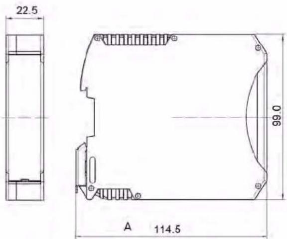
Dimensions: 114.5 H x 22.5 W x 99.0 D mm See Fig. 1, below
Power Requirements: 24 VDC ± 10%; 100 mA nom.; 160 mA max.
Input Overvoltage Protection: Up to 240 VAC RMS on all Signal and Excitation lines
ESD Protection: Up to 4 kV on all connections
Table 1
Model 5T70(V) Ranges (Nominal) and Accuracy per Excitation Setting ^1
(Accuracy given as % of full scale overall expected maximum error, following calibration)
| Range (mV/V) | Excitation | ||
| 2 VDC | 5 VDC | 10VDC | |
| 0.10 | — | — | 0.25 |
| 0.15 | — | — | 0.20 |
| 0.20 | — | — | 0.15 |
| 0.25 | — | — | 0.10 |
| 0.375 | — | — | 0.06 |
| 0.50 | 0.25 | 0.15 | 0.05 |
| 0.75 | 0.20 | 0.10 | 0.04 |
| 1.00 | 0.15 | 0.05 | 0.02 |
| 1.50 | 0.10 | 0.03 | 0.02 |
| 2.00 | 0.05 | 0.02 | 0.02 |
| 3.00 | 0.03 | 0.02 | 0.02 |
| 4.00 | 0.02 | 0.02 | 0.02 |
| 6.00 | 0.02 | 0.02 | 0.02 |
| 8.00 | 0.02 | 0.02 | 0.02 |
| 12.00 | 0.02 | 0.02 | 0.02 |
| 16.00 | 0.02 | 0.02 | 0.02 |
1 See Table 2 in Appendix B for the "practical" ranges that apply to the 5T70(V) RANGE (RNG) setting. The first five ranges in the list apply only when the 5T70(V) is set to an excitation of 10 VDC.
2 With respect to bridge center (midpoint of excitation).
Isolation: 1500 VAC between input and output terminals; 1500 VAC between I/O terminals and power supply / communications terminals
Operating Temperature Range: -10°C to 70°C (14°F to 158°F)
Operating Relative Humidity: 5% to 95%, noncondensing
Transducer Types: Conventional 4-arm strain gage bridges, 120 Ω to 10 kΩ; zero range is 20% of the stated full scale. A screw terminal is provided for user-supplied shunt calibration resistor (see Fig. 6).
Input Ranges (Full-Scale): See Table 1, below; selectable when the 5T70(V) is configured (NOTE: the highest range selection accommodates actual inputs as high as 25 mV/V ^1 )
Excitation: Nominal 2.00 VDC @ 50 mA, 5.00 VDC @ 60 mA, or 10.00 VDC @ 90 mA; selectable when the 5T70(V) is configured. Default is 10 Vdc (±5V)
Accuracy: Dependent on range and excitation; see Table 1
Amplifier:
Common-Mode Range: ±1 V operating ^2
Common-Mode Rejection Ratio (at 1 V of Common
Mode): -100 dB at DC; -120 dB at 60 Hz ^4
text_image
22.5 99.0 A 114.5Fig. 1 5T Dimensions
1. INTRODUCTION
Input Impedance (Differential and Common-Mode): Greater than 10,000 MΩ
Offset: Initial: ±4 μV; vs. temperature: ±0.10 μV/°C; vs. time: ±5 μV/month
Gain Accuracy: ±0.02% of full scale typical, following calibration; see Table 1
Gain Stability: vs. temperature: ±25 ppm/°C; vs. time: ±10 ppm/month
Analog Filters: 0.2, 2, 20, 200, or 2000 Hz, independently selectable for each output
Analog Outputs: Filtered ± 0 to 5 VDC (for the Model 5T70) or ± 0 to 10 VDC (for the Model 5T70V), with linearity maintained for 20% over range. For the Model 5T70, Output A is continuous, and Output B is switchable via logic "Enable" line (see Section 2.F).
Logic Inputs (Enable, Shunt Positive, Shunt Negative Nominal 0 - 5 V, where 5 V = Logic 1 ("true"); ±25 V without damage; noise immunity 1 V; internal pull-up nom. 5 kΩ; all inputs assume Logic 1 state in the absence of connection
Power Status Indicator Light: Green/Yellow/Red; indicates module input and communications status (see Section 5.A)
TEDs Status Indicator Light: Green/Red; indicates TEDs Load status RED: TEDs Load for 2 seconds when TEDs - READ switch is depressed. GREEN for 2 seconds if load is valid. GREEN LED is active when the USB port is accessed. Both "OFF" under normal run conditions.
TEDs - READ Switch: Depressed to load Transducer Electronic Data Sheet into the 5T70(V) conditioner for factory calibration. Typically accomplished when first installed/connected or for reverification purposes.
text_image
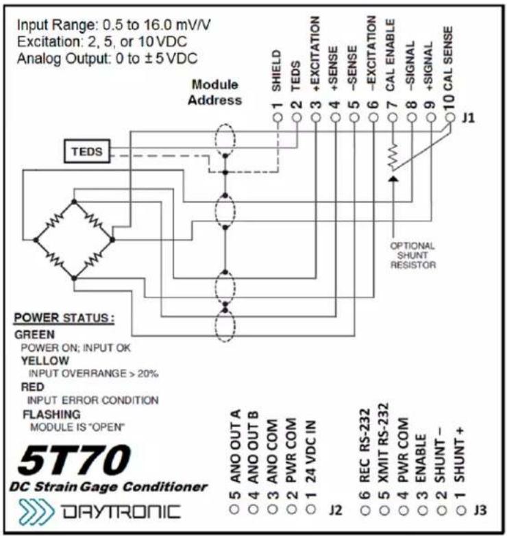
Input Range: 0.5 to 16.0 mV/V Excitation: 2, 5, or 10 VDC Analog Output: 0 to ±5 VDC Module Address TEDS POWER STATUS: GREEN POWER ON; INPUT OK YELLOW INPUT OVERRANGE > 20% RED INPUT ERROR CONDITION FLASHING MODULE IS "OPEN" 5T70 DC Strain Gage Conditioner DAYTRONIC J1 J2 J3 J4 J5 J6 J7 J8 J9 J10 SHIELD TEDS +EXCITATION +SENSE -SENSE -EXCITATION CAL ENABLE -SIGNAL +SIGNAL OPTIONAL SHUNT RESISTOR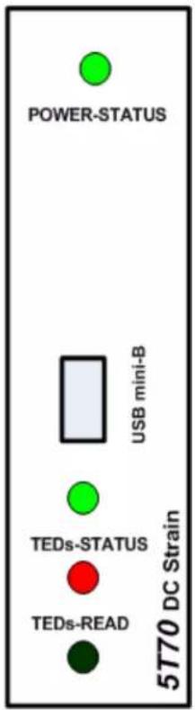
text_image
POWER-STATUS USB mini-B TEDs-STATUS TEDs-READ 5770 DC StrainModel 5T70 DC Strain Gage Module - Side Label and Front View
Access to the USB port or TEDs switch by gently pulling the front plastic cover (from the bottom side) so the cover rotates open from the top.
1. INTRODUCTION
1.C INSTALLING AND RUNNING THE 5D CONFIGURATOR SOFTWARE for the 5T70(V) OPERATION
PLEASE NOTE: The 5D-CONFIG-W software requires an operating system of Windows 95 or higher which takes approximately 3.5 MB of hard-drive space. The internal conditioner is based on the 5D technology with the TEDs added feature.
For more information on "Using the 5D Configurator," see Section 3.A of this manual.
To INSTALL the 5D Configurator Software,
- Make sure to close all applications before starting the installation. Use Windows Explorer to access programs.
- Insert the CD supplied with your 5T78(V) or you can download the zip file by logging into the www.daytronic.com web site, under Software Downloads - 5D Windows Configurator - 5DCONFIG-W.
- With the software copied over to your designated folder, Unzip the contents - there will be three files extracted - CONFIG5D, SETUP and SETUP.LST. Double-click on the application file SETUP to begin the installation process.
- Acknowledge to begin installation or Exit back to main screen.
- Begin the installation process by Double-clicking on the computer icon box as shown below. If desired, you can designate a different file location for the 5D Configuration program or exit the process
text_image
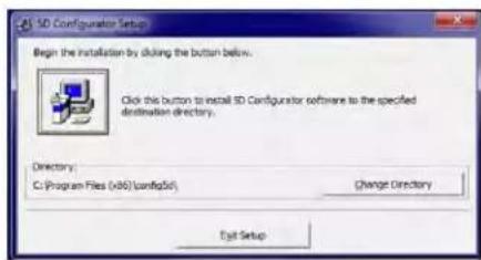
SD Configurator Setup Begin the installation by doing the button below. Click this button to install SD Configurator software to the specified destination directory. Directory: C:\Program Files (v86)\config\std Change Directory Edit Setup- Once enabled, the program will install in the designated file directly. When completed, a popup will appear indicating completion. Acknowledge by clicking OK. This will return the computer display to your original Windows Explorer screen.
- Verify the program loaded by selecting the Main Start Menu of the computer and locating the "5D Configurator" icon.
- To RUN the Configurator, go to your Windows popup Start menu, select Programs, and click 5D Configurator. The follow screen will appear
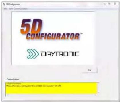
text_image
3D Configuration 5D CONFIGURATOR™ DAYTRONIC Get Communication Connect to Web Please select the configuration file as available communication with a 70.- To UNINSTALL the 5D Configurator Software,
a. Go to the Windows popup Start menu, select Settings, and then select Control Panel. Then double-click on the button called Add/Remove... (or Add or Remove Programs).
b. Select "5D Configurator" from the list of programs and click the appropriate button to remove it.
c. When asked whether you're sure you want to completely remove the 5D Configurator and all its components, answer Yes to uninstall (or No to abort).
d. NOTE: This procedure will NOT delete any “*.fiv” 5D CONFIGURATION FILES currently in your Configurator installation directory which were created through the Configurator software. In fact, if you have created any such files, you will be told that the directory itself cannot be removed (click Ok to exit this message).
File Menu
New - Starts blank configuration
Open.... - Retrieves stored configuration
Close - Clears existing configuration
Save - Stores ".fiv" configuration file
Save as.. - Stores renamed ".fiv" file
Exit - Exit configuration program
Serial Communications Menu
Initialize Port - Selects COM port to use
Terminal - Used for direct command and response setup and queries to the 5T Module
Upload 5D Module -- Retrieves connected module's configuration information to begin setup changes and calibration
2. CONNECTIONS
2.A INTRODUCTION
Fig. 3 Power, Transducer, Logic, and Analog Output Connections
The Model 5T70(V) I/O CONNECTIONS are via screw terminals which will accept wire sizes from AWG 12 to 26. NOTE: The recommended transducer cabling would be eight wires, individually shielded, twisted pair - wired as indicated (Fig. 1).
Sense lines must be connected at the transducer (as recommended) or at the 5T70(V) screw terminals - as a minimum. Table 1 denotes screw terminal assignments.
Table 1 - Model 5T70 Terminal Assignments
| Transducer Connector Pin Number | Screw Terminal | |||
| Terminal Label | Function | |||
| Top J1 - 1 | 1 |  | [7] | SHIELD |
| Top J1 - 2 | 2 | TEDs | TEDs INPUT | |
| Top J1 - 3 | 3 | + EXC | + EXCITATION | |
| Top J1 - 4 | 4 | + SEN | + SENSE | |
| Top J1 - 5 | 5 | - SEN | - SENSE | |
| Top J1 - 6 | 6 | - EXC | - EXCITATION | |
| Top J1 - 7 | 7 | CAL ENB | CALIBRATION ENABLE | |
| Top J1 - 8 | 8 | - SIG | - SIGNAL | |
| Top J1 - 9 | 9 | + SIG | + SIGNAL | |
| Top J1 - 10 | 10 | CAL SEN | CALIBRATION SENSE | |
| Logic I/O Connector Pin Number | Screw Terminal | |||
| Terminal Label | Function | |||
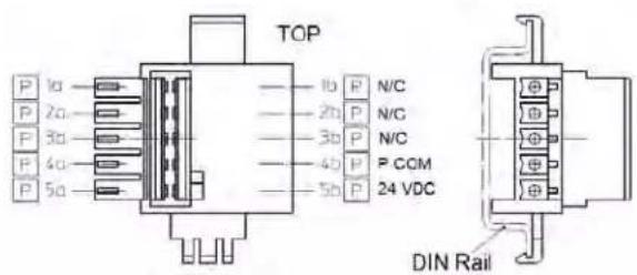
| Bottom J3 - 1 | 1 |  | SHP | SHUNT POSITIVE |
| Bottom J3 - 2 | 2 | SHN | SHUNT NEGATIVE | |
| Bottom J3 - 3 | 3 | ENB | ENABLE | |
| Bottom J3 - 4 | 4 | P COM | POWER COMMON | |
| Bottom J3 - 5 | 5 | XMIT | TRANSMIT RS232 | |
| Bottom J3 - 6 | 6 | REC | RECEIVE RS232 | |
| Power and Analog Connector Pin Number | Screw Terminal | |||
| Terminal Label | Function | |||
| Bottom J2 - 1 | 1 |  | 24 V | 24 VDC POWER INPUT |
| Bottom J2 - 2 | 2 | P COM | POWER COMMON | |
| Bottom J2 - 3 | 3 | A COM | ANALOG COMMON | |
| Bottom J2 - 4 | 4 | ANO B | ANALOG OUTPUT B | |
| Bottom J2 - 5 | 5 | ANO A | ANALOG OUTPUT A | |
| DIN Power Connector 5M-PCON Pin Number | Screw Terminal Function | |||
| DIN PCB - 1 | 1 |  | N/C | |
| DIN PCB - 2 | 2 | N/C | ||
| DIN PCB - 3 | 3 | N/C | ||
| DIN PCB - 4 | 4 | POWER COMMON 24 | ||
| DIN PCB - 5 | 5 | VDC POWER INPUT | ||
2. CONNECTIONS
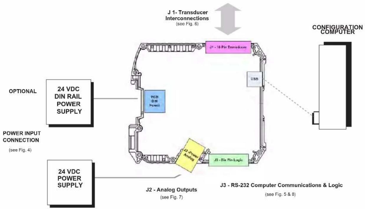
flowchart
graph TD
    A["OPTIONAL"] --> B["24 VDC DIN RAIL POWER SUPPLY"]
    C["POWER INPUT CONNECTION (see Fig. 4)"] --> D["PCB DIN Power"]
    E["J1 - 16 Pin Transducer"] --> F["J1 - 16 Pin Transducer"]
    G["24 VDC POWER SUPPLY"] --> H["J2 - Analog Outputs (see Fig. 7)"]
    I["J3 - Six Pin Logic"] --> J["J3 - RS-232 Computer Communications & Logic (see Fig. 5 & 8)"]
    K["CONFIGURATION COMPUTER"] --> L["USB"]
    M["J1 - Transducer Interconnections (see Fig. 6)"] --> N["Configuration Computer"]
General 5T70 Connections
2.B POWER AND GROUND CONNECTIONS
The 5T70(V) requires a user-supplied external source of 24 VDC, regulated to ±10%. Nominal consumption is 100 mA; maximum is 160 mA. Fig. 5 on the next page shows how the positive and negative power leads are tied, respectively, to the +24 VDC and POWER COM-MON terminals of the 5T70's screw terminal connector.
If more than one 5T module are mounted together, you can power the entire chain by connecting the supply to the DIN mount connector accessed via the 5MPCON connector and the DIN clip are of the 5T70(V) unit to any given module. The +24 VDC terminals of adjacent modules are then tied pin-to-pin, as shown in Fig. 5. The cable shield is tied to POWER COMMON.
When the 5T70(V) is properly powered, the module's POWER STATUS indicator light will be GREEN—unless there is presently an input over range of 20% or more, an incoming CARRIAGE RETURN, or a serious hardware/software malfunction (see Section 5.A).
CABLE SHIELDING
Proper shielding of cable wires or twisted pairs—as shown in Figs. 5 through 8—is strongly recommended to minimize the production of unwanted electrical noise from capacitive and inductive effects.
In the I/O cabling diagrams (Figs. 6 through 8), only the "connector end" of each cable shield is shown, as represented by a gray circle surrounding either a single wire or a TWISTED PAIR of wires within the cable. Unless otherwise stated, every shield should be grounded to the appropriate common or ground terminal only at the connector end. The drain wire tying the connector end of the shield to common/ground should be as short as possible.
MODULE GROUNDING
For optimum ESD/EMI immunity, every 5T module should be LOCALLY GROUNDED. Use a single drain wire to connect the module's CHASSIS GROUND which is connected via the spring DIN clip on the rear of the unit. If needed, a local earth ground can be connected to SHEILD terminal. The drain wire should be as short as possible.
POWER AND GROUND CONNECTIONS
Fig. 4
J2- Fixed Connector - Bottom side of 5T70(V)
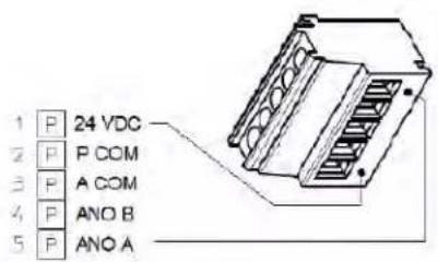
text_image
1 P 24 VDC 2 P P COM 3 P A COM 4 P ANO B 5 P ANO AOptional DIN Power Connection 5M-PCON
text_image
TOP 1b P N/C 2b P N/C 3b P N/C 4b P P COM 5b P 24 VDC DIN Rail2.C COMMUNICATIONS CONNECTIONS
The 5T70(V) unit has two computer communications ports available, Mini-B USB which is accessed through the front panel of the unit and a three-wire RS232 interface which is located on connector J3 as described in figure 5. Only one port should be utilized at a time. The RS232 interface observes a fixed protocol of 19,200 baud, 8 data bits, 1 stop bit, and NO parity—with no software or hardware "handshake." The Configurator software will automatically set to this protocol the computer COM PORT selected for communications with the 5T unit.
The Mini-B USB port is a standard interface and will require the computer to use a USB driver. For Windows 10 machines the driver should be found during installation, since it is included in the OS. For Windows 7 and earlier - driver
https://www.st.com/en/development-tools/stsw-stm32102.html
will need to be installed by the user. It is a large file which can support computers running back to Windows 98.
Notes:
While 5T / PC serial communications will usually take place through the 5D CONFIGURATOR software described in Section 3, a "terminal emulation" program (either conventional or customized) can also be used to issue standard mnemonic commands to the module, and to receive module responses.
Unless you are using the 5D Configurator software, it is first necessary to issue an OPEN (OPN) command to initiate single-point communications between the computer issuing the command and a specific 5T module (see Section 4.A).
Fig. 5 RS-232 or Mini-B USB Serial Communications Connections
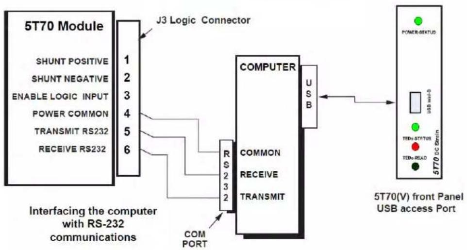
flowchart
graph LR
    A["5T70 Module"] -->|J3 Logic Connector| B["COMPUTER"]
    B --> C["USB"]
    C --> D["5T70(V) front Panel USB access Port"]
    subgraph Interfacing the computer with RS-232 communications
        E["SHUNT POSITIVE"] --> F["1"]
        G["SHUNT NEGATIVE"] --> H["2"]
        I["ENABLE LOGIC INPUT"] --> J["3"]
        K["POWER COMMON"] --> L["4"]
        M["TRANSMIT RS232"] --> N["5"]
        O["RECEIVE RS232"] --> P["6"]
    end
    subgraph COMPORT
        Q["RS 2 3 2"] --> R["COMPUTER"]
        S["COMMON"] --> T["COMPUTER"]
        U["RECEIVE"] --> V["COMPUTER"]
        W["TRANSMIT"] --> X["COMPUTER"]
    end
    D --> Y["5T70(DC Strain)"]
    Y --> Z["POWER-STATUS"]
    Y --> AA["TEDs STATUS"]
    Y --> AB["TEDs READ"]
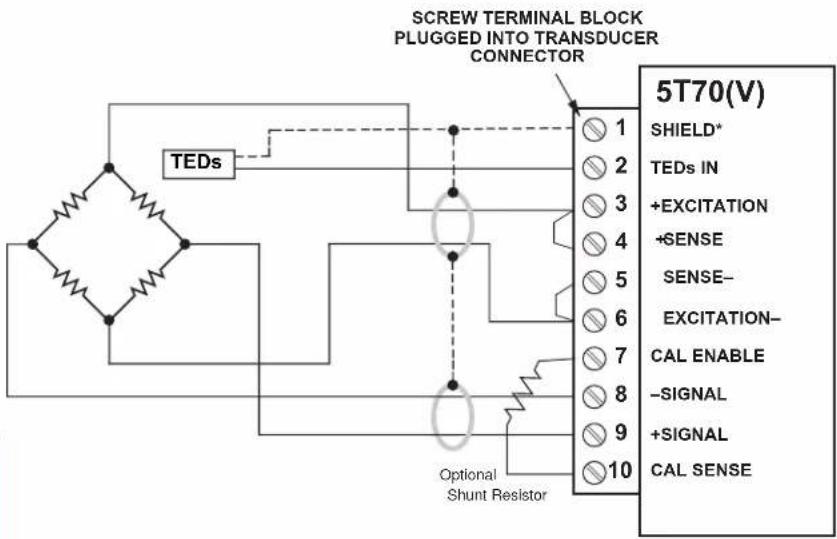
2.D TRANSDUCER CONNECTIONS
Each wire or jumper of the transducer cable is to be firmly secured to the appropriate screw terminal of the terminal block that plugs into the 5T70(V)'s 10-pin TRANSDUCER CONNECTOR.
4-wire connections to a full-bridge strain gage transducer are given in Fig. 2.a. This wiring is to be used with a cable of 18-gage conductors which is under 20 feet in length. In this case, the +SENSE and -SENSE lines are tied to the corresponding EXCITATION lines at the 5T70(V) CONNECTOR. It is recommended that the resistance of the conductors not exceed 0.0001 of the bridge resistance.
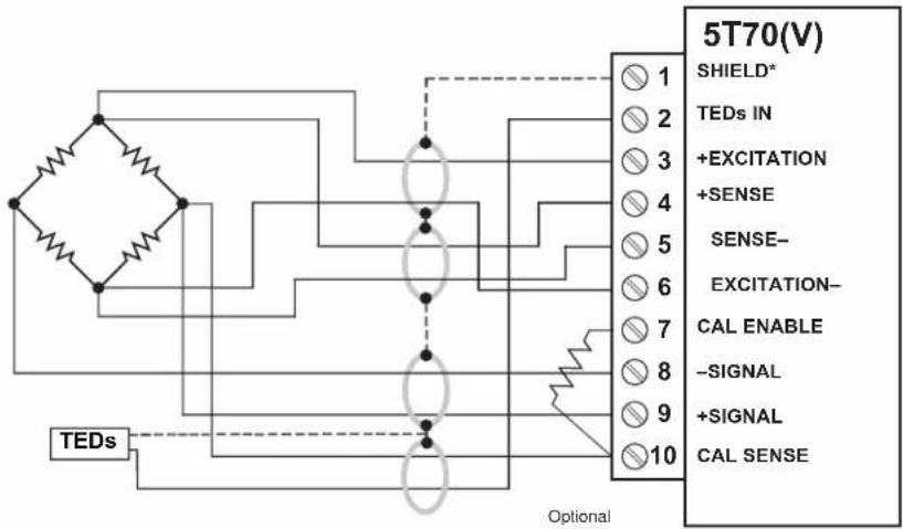
8-wire connections to a full-bridge strain gage
transducer are given in Fig. 2.b. This wiring is to be used when the cable is 20 feet or longer, or when fine wire is used. In this case, the +SENSE and -SENSE lines are tied to the corresponding EXCITATION lines (and the CAL SENSE line to the +SIGNAL line) at the transducer. Note also the extra wire connected to the -SIGNAL line at the transducer but left unconnected at the 5T70(V). This wire is to be paired with the CAL SENSE line to establish proper shielding and to avoid asymmetrical dynamic loading.
When an optional SHUNT RESISTOR is being used in TWO- POINT (DEADWEIGHT) calibration of the 5T70(V) (Section 3.D), it should be tied across Terminals 7 (CAL ENABLE) and 10 (CAL SENSE) of the Transducer Connector. For independent activation of the shunt for either a positive or negative upscale reading.
Fig. 6 Model 5T70(V) Transducer Connections
Fig. 6.a
4-Wire Strain
Gage Cabling
(under 20 ft. in length)
NOTE:
The 5T70(V) unit is based on the IEEE-1451.4 Class 2 Mixed-Mode Interface for the transducer. Class 2 has a dedicated Digital Data output line (shown as the dotted line in the diagram) for the one wire device and Data Return which is tied to the 5T70(V) shield line which drains to Chassis common of the unit.
Fig. 6.b
8-Wire Strain
Gage Cabling
(20 ft. or longer)
text_image
SCREW TERMINAL BLOCK PLUGGED INTO TRANSDUCER CONNECTOR TEDs Optional Shunt Resistor 5T70(V) SHIELD* TEDs IN +EXCITATION +SENSE SENSE- EXCITATION- CAL ENABLE -SIGNAL +SIGNAL CAL SENSE* (NOT ISOLATED; connects internally to CHASSIS GROUND)
text_image
5T70(V) SHIELD* TEDs IN +EXCITATION +SENSE SENSE- EXCITATION- CAL ENABLE -SIGNAL +SIGNAL CAL SENSE TEDs OptionalOptional Shunt Resistor
2.E ANALOG OUTPUT CONNECTIONS
Fig. 7 shows how an A/D Card, datalogger, recorder, or other external device connects to one of the Model 5T70's two ANALOG OUTPUTS, using the 5 Pin J2 connector shown in Fig. 3.a.* The 5T70V's two ±10-V outputs and the 5T70's two ±5-V outputs are similarly connected, using the corresponding screw terminals shown in Fig. 3.b.
Each output is single-ended and returns to ANALOG COMMON.
* Outputs A and B are independently filtered. For the standard Model 5T70, Output A is continuously available, while Output B may be switched on and off via the logic "ENABLE" line (see Section 2.F, below).
Fig. 7
5T70(V) Analog Output Connections

flowchart
graph LR
    A["5T70(V)"] --> B["J2 - Fixed Screw Terminal Connector"]
    B --> C["SHIELD"]
    C --> D["EXTERNAL DEVICE - PC, Meter, PLC, etc."]
    A --> E["ANALOG A"]
    A --> F["ANALOG B"]
    A --> G["ANALOG COM"]
    A --> H["POWER COM"]
    A --> I["24 VDC POWER"]
    B --> J["+ EXTERNAL DEVICE"]
    B --> K["- EXTERNAL DEVICE"]
2. CONNECTIONS
2.F LOGIC INPUT CONNECTIONS
The Model 5T70(V) J3 connector terminals contain three "positive-true" logic-level inputs; the screw-terminal connector of the Model 5T70(V) which are used to activate a SHUNT POSITIVE, SHUNT NEGATIVE or the ENABLE INPUT
- ENABLE — used to switch the module's ANALOG OUTPUT B
- SHUNT POSITIVE — used to close the optional calibration shunt for a positive upscale reading and to reopen the shunt (see also Section 4.B)
- SHUNT NEGATIVE — used to close the optional calibration shunt for a negative upscale reading and to reopen the shunt (see also Section 4.B)
Fig. 8. shows how these command inputs can be independently applied to a 5T70's J3 connector, without the need of an external logic reference supply. You may also use active TTL logic, as illustrated in Fig. 8, to produce the "ENABLE ANALOG OUTPUT B," "SHUNT POSITIVE," and/or "SHUNT NEGATIVE" condition for the 5T70.
* For all three inputs, the Logic 1 state is represented by nominal 5 VDC and is the "true" state (indicated by the name of the input); the Logic 0 state is represented by nominal 0 VDC and is the "false" state. Thus, when the "Enable" input is at Logic 1, Analog Output B is enabled; when "SHUNT POSITIVE" is at Logic 1, the positive shunt calibration condition does NOT exist. Logic inputs may be generated directly from dry contacts (switches, relays, etc.), as in Fig. 8, or from solid-state logic systems. All inputs assume the Logic 1 state in the absence of any connection.

text_image
Fig. 8 Model 5T70 Logic Input Connections Switch Closure, No External Supply Model 5T70 J3 LOGIC CONNECTOR SHUNT POSITIVE 1 SHUNT NEGATIVE 2 ENABLE 3 POWER COMMON 4 TRANSMIT RS232 5 RECEIVE RS232 6 PUSH OPEN = Logic 1 (both shunts open: NO CALIBRATION) PUSH CLOSED TO P OR N = Logic 0 (+ or - shunt closed: SHUNT POSITIVE or SHUNT NEGATIVE ) SHIELD Push Button (NC) PUSHED = Logic 1 (Output B enabled) NOT PUSHED = Logic 0 (Output B not enabled)2. CONNECTION TEDs
2.G TEDs Input Connections
The Model 5T70(V) has the added features of a USB interface and a Transducer Electronic Data Sheet input per IEEE-1451.4 (TEDs) Class 2 MMI. Wiring of the TEDs enabled cable adaptor or transducer allows the user to automatically configure the sensor calibration characteristics to the 5T70(V) for a precision analog output matching the sensor's full-scale sensitivity and value per the manufacturer.
The user may configure or re-configure the 5T70(V) via the computer interface making it adaptable to the user's sensor application that requires stable, repeatable and noise free analog signals for control or data acquisition.
Fig. 9
Model 5T70(V) TEDs Input Connections
text_image
5T70(V) J1 - Removable Transducer Connector SHIELD TEDs INPUT + EXCITATION + SENSE - SENSE - EXCITATION CALIBRATION ENABLE - SIGNAL + SIGNAL CALIBRATION SENSE 1 2 3 4 5 6 7 8 9 10 SHIELD TEDs enable cable maybe utilized as well - refer to the sensor manufacturer for wiring code or pin assignments.3. CONFIGURATION AND CALIBRATION
3.A USING THE 5D CONFIGURATOR
NOTE: The 5T70(V) utilizes the 5D Configurator software which lets you define, store, edit, download, upload, and manage any number of "configurations" for a connected Daytronic "5T" Signal Conditioner Module.
Every real-world application of a 5T module requires its own unique configuration. A module "configuration" is a set of operating parameters that instruct the signal conditioner precisely how it is to process sensor-based measurement data. The information contained in a 5T module configuration includes module-specific setup parameters and calibration data. This information can be "up-loaded" via the TEDs one-wire input or manually entered by the user.
The 5D CONFIGURATION software was created for multiple 5D modules, which is still in effect however the 5T is considered a standalone conditioner and refer to as such for this manual.
Specifically, the 5D Configurator lets you
- set up and test serial communications between the PC running the Configurator software and the connected 5T module, USB or RS-232.
- enter or modify identifying and descriptive information for the connected 5T module, tag name, engineering units, optional description strings, and optional transducer model/serial number
- define module-specific setup values, including each module's analog filter cutoff frequencies, plus (for the Model 5T70(V)) the DC excitation level (2, 5, or 10 V)
- define or view general parameters relating to the individual module configurations, including file path and size, configuration description, calibration info., comments, etc.
• perform selected run-time operations, including
— both "absolute" and two-point (deadweight) calibration of the module
— sending one or more standard mnemonic commands to the module
— applying a positive or negative calibration shunt - download an individual module configuration to a specific module
Within the software it will reference "5D" - it should be understood the configuration software is communicating point to point with the internally integrated 5D conditioning module within the 5T70(V) unit.
- upload the current configuration to a new configuration file, for storage and/or editing
- upload an individual module configuration (to be appended to the presently open configuration file)
- "update" an existing module configuration based on the active setup values of the corresponding connected module
STARTING THE 5D CONFIGURATOR
Instructions for installing and running the Configurator software were given in Section 1.C.
After the Configurator starts up, you can do one of three things:
- OPEN AN EXISTING 5D CONFIGURATION by selecting Open... from the File menu
- CREATE A NEW 5D CONFIGURATION by selecting New... from the File menu
- UPLOAD A 5D CONFIGURATION by polling the connected module to a New Configuration using the Serial Communications entry tab.
An overview of the procedure for creating a new module configuration via the New... command is given in Section 3.C, below.
FILE MENU
New...
Select to create a new configuration
Open...
Select to open an existing configuration
Close
Select to close the open configuration
Save
Select to close the open configuration
Save As...
Select to save the open configuration using a new file name
Exit
Select to exit the Configurator program
3. CONFIGURATION AND CALIBRATION
3.B SUMMARY OF CONFIGURATOR MENUS
SERIAL COMMUNICATION MENU
Initialize Port
Selects the computer's communication port to be utilized - Com Port Definition
Terminal
Sends direct command and response syntax statements to the 5D modules. See section A.2
Upload 5D Module
When selected, will upload the connected 5T module.
In general, you will take the steps listed below to develop a new configuration for the connected 5T Signal Conditioner Module (although the exact sequence of steps may vary, depending on your own preference). Alternatively, you may initially wish to upload the existing configuration of the connected 5T module to form a new 5T configuration, which you may then proceed to modify as desired. In this case, you need not perform the "To Create a New 5D configuration" as listed in section 3.C
The Module Setup Parameters page displays in tabular form the most important setup parameters for all currently defined modules.
Once a given 5T module's setup configuration (Fig 5) has been completely entered (including all required calibration information), it may then be individually downloaded to that module. Or the entire "5D configuration" may be downloaded to the connected network, in which case each individual module setup within the collective configuration will be downloaded to its respective module.
HOME PAGE - SERIAL COMMUNICATIONS TAB

text_image
5D CONFIGURATOR™ DAYTRONIC Exit Communications Total Post installation. Please select open a configuration file or establish communication with a 5DFig. 10a
NEW CONFIGURATION PAGE w/ default modules
text_image
10 Configuration File: Serial Communication Model No. Small No. Tag Name Description Transducer SN F5 only S470 11111 description here description here Transducer ID: 0 Total Type: 50:30 Add/Module Create Module End Communications: Please select a file or open in a new configuration, check up on establish with 3D to start Place the focus contains the description at the 3D that is in be collubed and left offFig. 10b
3. CONFIGURATION AND CALIBRATION
3.C OVERVIEW OF THE CONFIGURATION PROCESS
To Create a New 5T configuration - OFF LINE
- Using the New... menu command, open to a new (blank) configuration. Select 5D70 or 5D70V from the available 5D Series Conditioner Modules which appear in the pull-down selection box on the left side of the menu. Click the Add Module button on the Module Setup page (Fig 10b) to add the module to the configuration. Once completed, double click on the selected Module Model No. in the worksheet area to begin configuration.
- With the first Module selected, the Module Type Absolute Menu page (Fig 11a) will be displayed allowing the user to configure the specific module's parameters as needed. Once the specific module parameters are entered "Exit" the Absolute Configuration Page and save to file.
- When the "New" configuration is downloaded to a connected 5T, the program will query the modules and allow for proper serial number assignment and configuration. The module configuration will be assigned it unique serial number, replacing the "11111" default ID. Save the configuration as needed on "Exit" of the Summary Configuration Page (Fig 11b) or proceed to the "two point" calibration process for the module as describe in 3.D.
To Upload a connected 5T configuration - ON LINE
- Using the Upload 5D Module... command. Under the "Serial Communications" tab on the Home page. Click on the "serial communications" tab and click on the "Upload 5D modules" tab. Selecting this tab will initiate an uploading of the connected 5T module configuration setup. Once completed the specific parameters are displayed on the Summary workspace screen. Double click on the specific module to review or change. Through the Model Type Absolute Menu page, the user can access the "two point" or "dead-weight" calibration of the specific module.
- The Module Type Absolute Menu Page is used to review, alter or process through the Module's parameters for a specific 5T that was uploaded, or created as "new". It is called "absolute" due to the module's calibration parameters being entered with known documented values such as sensitivity, full scale value, zero offset, expected load, etc. - which are downloaded to the module prior to a "two point" calibration verification. Menu through the parameters to configure the module for the application. Once a field value has been changed, the "Download" button will be enabled to allow the configuration to be sent to the 5T module. Note when completed the "Calculated Parameters" (which is the result of the entered menu values) will be the same as the "Current Parameters" (which are the values stored into the 5T Module Configuration to be sent the specific 5T module. Note when completed the "Calculated Parameters" (which is the result of the entered menu values) will be the same as the "Current Parameters" (which are the values stored into the 5T Module
ABSOLUTE CONFIGURATION PAGE w/ default module
text_image
Current3D configuration Module Type M470 3D maximum output in 18 Vdc Serial Number (191) Tang Number Description Transducer model/total number Transducer U Eng Units Transducer Rated Full Scale Load 1 Eng Units Maximum Expected Transducer Load 1 Eng Units Transducer sensitivity 2 HIV Zero Offset Compensation 5D Input 2 Eng Units Full scale negative transducer input 1 Eng Units Excitation 5 Vdc A output AnalogFilter 5Vdc B output AnalogFilter 5Vdc Cancel changes Set Save Communication The 5D includes a set attachment to the total output. This result is used to describe the application or to engage interconnection. Standard DataNetFig. 11a
SUMMARY CONFIGURATION PAGE w/ uploaded module

text_image
3D Configurator File: Serial Communication Model No. Small No. Cap Name Description Transact Soft TS-045 Sv70 A04 2 D 171,75490 2000.00 5d Type Sv80 Add Module Delete Module Down Load Set Communications: Conforming to TO return Drive tracking configurator to SD effort Fixed configuration download. To modify configuration measure over SD configurations for developed and do Adjust free...Fig. 11b
ABSOLUTE CONFIGURATION PAGE w/ uploaded
text_image
Module Type:5478 SD maximum output is 10 Vdc Serial Number x54 Tiny Hetero Description Transducer mode/panel number 171.2688 Transducer Rated Full Scale Load 399.40 Maximum Exposed Transducer Load 399.40 Transducer sensitivity 1.54780 Zero Offset Compensation SD Input 100.0000 Full scale negative transducer input <100.00 Excitation 10 Vdc A output Analog filter 200Hz B output Analog filter 200Hz Cancel change Fail Save Standard parameters Found B module The full gate can be used to determine the parameters for any other functions Detailed Callboard 10Vdc-018Fig. 11c
3. CONFIGURATION AND CALIBRATION
ABSOLUTE CONFIGURATION PAGE parameter information
Changable user parameters -
Description - User entered description (up to 32 characters) scratch pad field for general module information
Tag Name - Short name field (16 characters) for ID information.
Transducer Model / Serial Number - User information for traceable connection of module to the sensor
Engineering Units - User information field for transducer measurement value
Transducer Rated Full Scale Load - Specification information of the transducer's rated capacity. Affects gain calculation.
Maximum Expected Transducer Load - Application information of the transducer's working capacity. Optimizes gain level.
Transducer sensitivity - Entry of the transducer's electrical characteristic, typically obtain from calibration document of the sensor
Zero Offset Compensation 5D Input - Select Offset value in Engineering Units or is Electrical Units
Offset value - Zero offset of the sensor (range is +/- 20% of full scale value)
Full Scale Negative Transducer Input - Used to calculate the symmetry compensation value level.
Excitation Frequency or Level - Module specific parameter for power to the sensor connected to the module.
"A" Output Analog Filter - Selects 3 db corner response on the analog output signal
"B" Output Analog Filter - Selects 3 db corner response on the analog output signal
Information parameters -
Module Type - 5D Module Model Identification (5D70 for the 5T70 and 5D70V for the 5T70V unit
5D Maximum Output - Identifies the module's full-scale output level.... 5V or 10V unit.
Serial Number - ID number of the Module used to address the unit for upload-download parameters
Download - Initiate downloading of configuration parameters to the identified module
Cancel Changes - Clears changes to the module's calculated parameters
Exit- Returns user to Summary page or queries for a "save configuration" if needed.
Save - Queries user for file information to save the configuration.
Two Point Calibration - When enable via changes, will enter the "Two-Point" menu page for on-line calibration process
Next 5D - Sequences to the next active 5D module in the current configuration (not used with the 5T70(V) process)
Last 5D - Sequences to the last active 5D module in the current configuration (not used with the 5T70(V) process)
Calculated Parameters - Absolute calibration calculated command parameters to be sent to the module for update
Current Parameters - Actual command parameters that are present in the module which affect calibration.
Date Last Calibrated - Recorded date of last calibration of the module.
3. CONFIGURATION AND CALIBRATION
3.D 5T70(V) CALIBRATION
CALIBRATION OVERVIEW
Calibration of the 5T70(V) is accomplished by the following method for a precision analog output -
1) Using the Transducer Data Sheet memory chip within the transducer or cable adapter. This process is initiated via the front panel "TEDs Load" switch being depressed. This action will load the one-wire data into the 5T70(V) unit via the ASCII commands including the Module Parameter statements. For complete calibration to manufacture's specification the TEDs data must be the "extended" TEDs format as over-viewed in Appendix C, considered Absolute Calibration.
2) Absolute Calibration - The process of the user entering the transducer parameters manually, typically from transducer's calibration document from the manufacture or re-certified calibration laboratory, using the 5D configuration computer software. This method is like the TEDs method in which data is entered via the ASCII commands, only manually.
3) Dead Weight Method - Using the existing TEDs or Absolute Calibration information and refining the calibration to match the application and verifying end to end (transducer to analog output) with a known physical parameter, typically "Zero" and "Nominal Working Span". This is the recommended method to verify all aspects of the measurement.
4) Shunt Calibration Method - Using a known resistive imbalance across the transducer's bridge to simulate the electrical effect of the transducer at a known value. This "SHUNT" value can be supplied by the transducer manufacturer or calculated. This method is similar to the "Dead Weight" method however there is no "physical" stimulus of the transducer. Shunt calibration is a convenient method for verification checks due to its repeatability but is less accurate as a measurement.
Method 1: Using the Transducer Data Sheet (TEDs) memory chip within the transducer.
1) With the sensor wired to the 5T70(V) as shown in Figure 6 (a or b) and the one wire digital line is connected to the "TEDs" input terminal and the "TEDs Return" line is connected to the SHIELD terminal. Ensure all connections to the Module have been accomplished. Do not connect the USB or RS-232 interface.
2) Power up the 5T70(V) unit with 24 Vdc power. Wait 15 minutes for temperature stabilization of the conditioner and transducer.
3) POWER STATUS should be "Green". TEDs indicators should be off.
4) Depress and released the "TEDs READ Switch". RED LED will turn ON and GREEN LED will be off. The POWER STATUS LED should be GREEN and blinking - indicating communications have been established. When the POWER STATUS LED turns to solid GREEN - the TEDs information has been loaded. TEDs STATUS GREEN LED will turn on for two seconds, then go off. Both the RED and GREEN LEDs should be off, indicating a successful TEDs load to the 5T70(V) unit.
If there is a failure to load, the TEDs STATUS RED LED will turn on and the unit will perform a power recycle event for the user to re-try the process.
5) TEDs information will be stored in non-volatile memory of the 5T70(V) unit. If needed, the USB interface can be connected at this time.
6) Using the 5D configurator software, the user can change, modify or upload the setup parameters as needed. This can be accomplished by using the Mini-B USB port (or RS232 terminals) to the unit and launching the 5D software as described in section 3 of the manual.
Note: Once the 5T70(V) has loaded the TEDs information from a previous calibration cycle, the TEDs status lights are OFF except if the USB port is active. The user can "re-load" TEDs by depressing the TEDs Switch and this will configure the conditioner to the TEDs information.
If changes were made using the configuration software, these parameters will be over-written by the TEDs process and will reflect the manufacture's data as stored in the one wire chip.
If using the configuration software, the "Zero Offset Compensation" value from TEDs is in Electrical units...mV. The software defaults to Engineering Units and will need to be assigned by the user for Electrical units.
3. CONFIGURATION AND CALIBRATION
3.D 5T70(V) CALIBRATION
CALIBRATION METHOD 2, 3 & 4 - ABSOLUTE, DEAD WEIGHT AND SHUNT
To verify or calibrate a 5T70(V) after a TEDs upload or by other means - the first step is to enter the User Configured parameters using the 5D configurator or similar software within the Absolute Menu Page as described in section 3.C. Specific parameters which affect calibration and typically contained within the transducer's supplied calibration document. They are:
- Transducer Rated Full Scale Load
- Maximum Expected Transducer Load (user defined)
- Transducer sensitivity
- Offset value (Zero)
- Full Scale Negative Transducer Input, Symmetry
-
Excitation level
-
Once the Absolute Calibration information has been downloaded to the module. The "Two Point" button will be enabled. On completion of the download, Click on the "Two Point" button. Once this action has been acknowledged, the "Two Point" page will be displayed.
-
Two Point calibration is used to "fine" tune the analog output of the module to reflect the actual values specific to the sensor's input to the module. Sometimes referred to as "dead weight calibration"; where the input is stimulated via a known load value or via the Shunt calibration value (if installed). Either method can be used.
-
With the analog output for the module under calibration - being measured (recommend a 5-digit voltmeter or similar device), begin the two point process by measuring the analog output of the Module at "Zero" sensor input. Click on the "Start Calibration" button. This will hi-light the "Zero Calibration" area. Select the "Count by" value needed for the adjustment. With a known Zero load, increment or decrement the Zero Calibration field to achieve the expected Zero analog output result. Range adjustment for Zero is +/- 20.00% of full scale. Note when changing values, it is done on-line with the module and a short delay will occur between the program action and the response of the analog output result.
-
Once the "Zero" parameter has been established, click "Continue" to proceed to the "Span Calibration Point". This field is used to adjust for any Gain or Span changes needed. While the sensor is loaded, or the positive shunt calibration is "Enabled", increment or decrement the Span Calibration value for the appropriate analog output value. Typically, this is done at the nominal working level of the sensor, which may or may not be full scale.
* Note: Due to analog adjustment of the module, step 3 & 4 should be re-checked. Gain adjustment will affect the "zero" setting. Utilize the "Back" button for this purpose.
Note: Shunt Positive and Shunt Negative activation buttons are provided to switch in the user installed "Shunt Calibration resistor. Click "Resume" will release the Shunt.
TWO POINT CALIBRATION PAGE

text_image
Two-point calibration Calibration Zonal Calibration 00.00 Span calibration point 12345 Negative symmetry adjustment (SVM) 1.68 Count by 0.01 Short Positive Short Negative Start Calibration Last Communications You will need a volume or inline device attached to the output of the SD. This will allow you to derive the exact value of the output, while you adjust the output of the SD at various inputs. Exit-
The 5T70(V) module has a "Negative symmetry adjustment" which is used to adjust the negative full-scale gain or span position. This control has an adjustment range of +/- 2.00 % of full scale. Utilize a known dead weight or Negative Shunt calibration for this purpose. Typically used in CW & CCW torque sensor output calibration or in Tension and Compression mode of a load cell to compensate for amplitude differences between full scale positive and full scale negative sensor output.
-
When completed, click on the "Continue" button until it is no longer hi-lighted. Click on "Exit" to save the changes to the module. When the downloading is complete - a menu to save the new configuration, file will appear. When done the Absolute Calibration Page will be display overviewing the calibrated module.

text_image
Typical Asymmetry3. CONFIGURATION AND CALIBRATION
CALCULATING "EQUIVALENT INPUT" FOR SHUNT CALIBRATION
In SHUNT calibration of the Model 5T70(V), the second of the two calibration points ("SPAN") is not produced by directly loading the source transducer, but by shunting a resistor of known magnitude across one arm of the transducer's strain gage bridge to simulate an upscale value of mechanical input in either the positive or negative direction. This known EQUIVALENT INPUT can then be entered as the DESIRED SPAN-POINT READING in the two-point calibration procedure, in order to determine a suitable MODULE SCALING FACTOR (MSF)
The transducer manufacturer will often supply the exact value of the transducer's equivalent input for a specific shunt resistor. If this is not the case, this value can be approximated from a knowledge of the:
Shunt Calibration Resistance (Rc)
Transducer's Bridge Resistance(Rb), and
Transducer's Full-Scale Sensitivity (K, in mV/V full scale).
X = Equivalent Input, % of full scale
Rb = bridge resistance, ohms
K = transducer sensitivity, mv/v full scale
Rc = calibration resistance, ohms (example: 59 K installed)
$$ X = \frac {2 5 0 0 0 \times R b}{K \times R c} $$
Sample Calculation: Assume that K = 3.000 mv/v for a 5000-pound load cell (full scale) with a bridge resistance of 350 ohms.
$$ \begin{array}{r l} X = \frac {2 5 0 0 0 \times 3 5 0}{5 9 0 0 0 \times 3} & = 4 9. 4 4 \% \text { of full scale } = 2 4 7 2 \text { pounds } \end{array} $$
The full-scale value of the transducer is 5000, in this example, with the analog output of the 5T70 either being 5 VDC or 10VDC depending on the version. With the SHUNT invoked and a true "ZERO" on the input of the conditioner, the analog output would be 2.472 or 4.944 VDC.
4. OPERATING CONSIDERATIONS
4.A SENDING A COMMAND TO THE 5T70(V)
The 5D Configurator software lets you send standard mnemonic commands to a connected 5T module, one command at a time, while viewing the module's exact response to each command as it is sent. This feature can be used not only to perform run-time adjustments to the module setup, but also to review the module's current configuration status and to issue run-time "imperative" commands as desired.
For use of the Configurator's Terminal... window, see page 3.2 in the 5D Configurator Home Page
* When using a terminal program (such as Windows HyperTerminal), remember that every 5T module's RS232 communications interface employs a fixed protocol of 19,200 baud, 8 data bits, 1 stop bit, and No parity—with no software or hardware "hand-shake."
** The QUERY MODULE ID (QID) command may be used to obtain the serial number of the 5T module. See the description of QID in Appendix A.
A "terminal emulation" program (either conventional or customized) can also be used to issue standard mnemonic commands to the 5T module, and to receive module responses.*
When using a terminal program, it is first necessary to issue an OPEN (OPN) command of the form
OPN=xxxx [CR]
* Note: OPN command is Case sensitive
in order to initiate single-point communications between the computer issuing the command and the single 5T module bearing SERIAL NUMBER "xxxx." The addressed module will respond to a valid OPN command with "ACK."**
When a given 5T module is "open" for communications, its indicator light will flash (see Section 5.A).
For a discussion of 5T Series command and response syntax, plus a description of all 5T setup, interrogation, and imperative commands, see Appendix A.
4.B APPLYING A POSITIVE OR NEGATIVE SHUNT TO THE 5T70(V)
As explained in Section 2.D, the 5T70(V)'s Transducer Connector provides terminals for installation of a shunt resistor supplied by the user. If desired, the resulting shunt may then be used in the 5D Configurator's TWO-POINT CALIBRATION procedure (described in Section 3.D), where it is automatically switched on to simulate a particular upscale value of mechanical input loading.
The shunt can also be independently controlled - at any time - either by the 5D Configurator software, by some other software command source, or by means of logic-level inputs to the module. For instance, you may wish to apply the shunt (independent of the normal calibration procedure) in the course of evaluating the performance of the strain gage transducer or configuration attached to the 5T70(V).
VIA CONFIGURATOR SOFTWARE
Applying a Positive or Negative Shunt to a Strain Gage Module" is accomplished via the "Two Point" calibration page, see page 3.5
VIA OTHER SOFTWARE COMMAND SOURCE
When communicating with the 5T70(V) through a conventional or customized "terminal emulation" program (see Section 4.A, above), you can issue the SHUNT POSITIVE (SHP) or SHUNT NEGATIVE (SHN) command to the currently "open" module (if it is a 5T70(V)) in order to close the calibration shunt for a positive or negative upscale reading, respectively. The RESUME (RSM) command may then be applied to open the calibration shunt, thus resuming the normal measurement mode. On receipt of SHP, SHN, or RSM, the 5T70(V) will respond with "ACK."
VIA LOGIC INPUT
See Section 2.F for an explanation of how the 5T70(V)'s "SHUNTPOSITIVE" and "SHUNTNEGATIVE" logic inputs can be connected for positive and negative shunt control, either by switch closure (no external supply required) or by active TTL logic.
4. OPERATING CONSIDERATIONS
When communicating with the 5T70(V) through a conventional or customized "terminal emulation" program, you can request the shunt status by sending a SHUNT STATUS (SHS) command. The 5T70(V) will answer with "P" (if the shunt is closed for positive calibration), "N" (if the shunt is closed for negative calibration), or "O" (if the shunt is open — i.e., shunt calibration of either polarity is OFF, as will be the case on module powerup and following a RESUME (RSM) command).
Note that if the response to SHS is a lower-case "p," "n," or "o," it means that the 5T70(V)'s shunt state was last set by means of a logic-signal command to the module. If the response is an upper-case "P," "N," or "O," it means that the specified shunt state was last set by means of an SHP, SHN, or RSM command issued to the module by the Configurator or some other com- mand source.
5. T ROUBLESHOOTING
5.A INTERPRETING THE POWER STATUS INDICATOR LIGHT
Shown on page 1.3, the 5T70(V)'s status indicator light serves to monitor the module's power, input, communications, and general health condition. The condition(s) represented by the light's three possible colors and color combinations are given below.
If the indicator light is flashing a single color, or is alternating between YELLOW and GREEN, it means that the module is currently "open" for communications (see Section 4.A, above). If the indicator is alternating between RED and GREEN, the module may or may not be "open." Obviously, if the indicator is lit with any color or color combination, it indicates that power is ON.
GREEN
Input signal is OK
YELLOW
Input signal is over 20% out of range
* This need not be a syntactically valid command (see Appendix A); it could, in fact, be any ASCII string terminated by a carriage return.
RED
Serious input condition detected (e.g., excessive current, overvoltage); could indicate transducer short or faulty cabling
YELLOW / GREEN
The module has received a mnemonic command* through its computer port (the yellow light will continue for about a second after receipt of the command-terminating carriage return)
RED / GREEN
Significant internal software error detected; contact the Daytronic Service Department
5.B INTERPRETING THE MODULE DIAGNOSTIC CODE
The last four characters of a 5T module's response to a MODULE IDENTIFICATION (MID) interrogation will always represent the module's current ERROR (or DIAGNOSTIC) CODE. Intended primarily as a program- ming tool, this code will help identify the nature of syntax and communications errors when they occur (when, for example, the computer receives a response of "NAK" instead of an expected "ACK").*
The first of the four code characters is an alphanumeric character (0 through 9, A through J, or Z). The next three characters are hexadecimal digits (0 through 9, A through F). Note that syntax and communication errors will combine additively to generate the respective digit. For example, a combination of serial communication errors "4" and "8" will yield a fourth character of "c" (= decimal 12).
The diagnostic code characters (X_1, X_2, X_3, X_4) are as follows:
FIRST CHARACTER (X1)
Indicates the three-letter MNEMONIC CODE of the previously received command:
5. T ROUBLESHOOTING
SECOND CHARACTER ( X_2 )
Indicates SYNTAX OR VALUE error:
X_2 Error
0 NONE
1 Syntax Error
2 Numeric Range Error
4 [NOT USED]
8 [NOT USED]
THIRD CHARACTER ( X_3 )
Indicates OTHER COMMUNICATION error:
X_3 Error
0 NONE
1 Unknown Mnemonic
2 Illegal Character in Mnemonic Field
4 [NOT USED]
8 [NOT USED]
FOURTH CHARACTER (X4)
Indicates SERIAL COMMUNICATION error:
X_4 Error
0 NONE
1 Break, UART Framing or Overrun Error
2 Receive Buffer Overrun
4 Insufficient Characters for Command
8 Received Before ACK/NAK (i.e., before a previous command had been answered)
SUMMARY OF 5T70(V) MNEMONIC COMMANDS
A.1 COMMAND AND RESPONSE SYNTAX
When issuing one or more commands to a 5T module by some means other than the 5D CONFIGURATOR software, please note the following:
- You must apply the OPEN (OPN) command to establish RS-232 communications with that module, as explained in Section 4.A ("Sending a Command to the 5T70(V)"). The QUERY MODULE ID (QID) command may be used to obtain the serial number of the connected module, prior to application of the OPN command to any specific module.
- SPACE CHARACTERS SHOULD NOT BE INCLUDED IN ANY COMMAND EXPRESSION.*
- ALL COMMANDS ISSUED TOA 5T MODULE ARE TO BE TERMINATED BY A SINGLE CARRIAGE RETURN ([CR]).** ALL RESPONSES BY THE 5T MODULE ARE ALSO TERMINATED BY A CARRIAGE RETURN ([CR]). This standard termination is not shown in the specific commands and responses listed below.
- After a command has been issued, no further characters should be sent until receipt of a response to that command (ACK, NAK, or ANSWER), or until at least 0.25 second has elapsed without response (indicating that no module is currently "open").
A setup (or "write") command instructs the module to store a setup value in EEPROM memory, and has the general form
[MNEMONIC]=[value][CR]
* The only exception to this rule are the following MODULE PARAMETER ("MP") commands: MP0, MP1, MP2, MP3, MP4, MP5, MP8, and MP9. Spaces may be included in the character string being entered via the "write" form of any of these commands (the MP6, MP7, MPA, MPB, MPC, and MPD commands should never include spaces). See below for the allowed syntax of each "MP" command.
** Commands are never to be terminated by CARRIAGE RETURN, LINEFEED([CR][LF]). Upon receipt of a setup command, the module will issue a response of either "ACKNOWLEDGED" or "NOT ACKNOWLEDGED"—i.e., of either
ACK[CR] or NAK[CR]
NOTE: The ACK[CR] message will be issued only after the received setup value has been successfully stored in the 5T module's EEPROM memory.
A response of NAK[CR] means that the module did not recognize the received ASCII string as a valid mnemonic command. If, for example, you were to issue a Command of RNG=6[CR], you would receive a response of NAK[CR] because there is a space following the equals sign (for space inclusion, see above); if you issued a command of SYN=0.05[CR], you would receive NAK[CR] because there is no "SYN" command; if you issued a command of SYM=+0.05[CR], you would receive NAK[CR] because the module does not recognize a plus sign in the SYM command.
An interrogation (or "read") command normally asks the module for the current value of a stored setup parameter, and has the general form
[MNEMONIC][CR]
Upon receipt of a valid interrogation command, the module will issue a response of
[value][CR]
If the interrogation command is invalid, the only response will be NAK[CR].
An imperative command does not store or request information, but rather tells the module to do something (for example, OPN=xxxx[CR] opens single-point communications with the module of serial number "xxxx"; SHN[CR] closes an open Model 5T70(V)'s calibration shunt for a negative upscale reading). The general form of an imperative command will usually resemble that of an interrogation command, being usually a single three-character mnemonic, although—as in the case of OPN—it can sometimes resemble a setup command.
Upon receipt of an imperative command, the module will issue a response of either ACK[CR] or NAK[CR], depending on whether or not the command has been recognized as valid—or, if a valid command has requested a given run-time status such as the current SHS value, it will issue that value (e.g., P, N, or O).
NOTE: The ACK[CR] message will be issued only after the action specified by the imperative command has been successfully performed.
A.2 5T70(V) SETUP AND INTERROGATION COMMANDS
AFL ANALOG FILTER
AFL=f A ,f B
Sets the analog output filter constant for the module's Output A (continuous output) to the number f_A (1 through 5) and for Output B (switched output) to the number f_B (1 through 5). Actual cutoff frequencies corresponding to filter constants are module-specific; for the Model 5T70(V), they are as follows:
$$ f _ {A} / f _ {B} = 1: 0. 2 \mathrm{Hz} $$
$$ f _ {A} / f _ {B} = 2: 2 \mathrm{Hz} $$
$$ f _ {A} / f _ {B} = 3: 2 0 \mathrm{Hz} $$
$$ f _ {A} / f _ {B} = 4: 2 0 0 \mathrm{Hz} $$
$$ \mathrm{fA} / \mathrm{fB} = 5: 2 0 0 0 \mathrm{Hz} $$
Note that if a low filter setting (0.2, 2, or 20 Hz) is selected for BOTH f_A and f_B , the settings must be the same.
AFL
Reads current filter-constant values; returns f_A, f_B .
ALSO NOTE: When the MID command is issued within 5 seconds of powerup to a module with the "ENABLE" line at the Logic 1 state, a MID response will be returned even though that module has not been specifically "opened" by means of the OPEN (OPN) command (see below). This feature is typically used in the initialization routine of certain Daytronic "5DMB" motherboard installations and not recommended to be used with the 5T70(V) unit since the primary interface to this module is USB - which is point to point not daisy chained communications. Unless you are sure that no more than one 5D module of the connected network is presently "enabled," do not issue a MID command within 5 seconds of network powerup.
EXC EXCITATION
EXC=v
Sets the module's excitation voltage to v, where v = 1 (for 2 VDC), 2 (for 5 VDC), or 3 (for 10 VDC).*
EXC
Reads current excitation voltage setting; returns 1, 2, or 3.
MID MODULE IDENTIFICATION
MID
Reads the module's current ID and diagnostic information string. Returns 5Dnn,xxxx,hhhh (where "5Dnn" is the Model Number, "xxxx" is the 4-character alphanumeric Serial Number, and "hhhh" is the 4-character hexadecimal- ASCII ERROR CODE—see Section 5.B).
NOTE: There is no "write" form of the MID command.
MIO MODULE INPUT OFFSET
MIO=m
Sets the pre-amplified (analog input) offset to the value m (% of selected full-scale input range—see RNG, below), where -20 ≤ m ≤ 20 . NOTE: The MIO value must be expressed in the format of XX.XX (% of full-scale range), with or without minus sign (e.g., MIO=01.33 and MIO=-14.50 are acceptable; MIO=1.33, MIO=-14.5, and MIO=+14.50 are not).
MIO
Reads current module input offset value; returns m.
MP1 through MPD MODULE PARAMETER
Used by the 5D CONFIGURATOR software to write and read miscellaneous module configuration information, as follows (each MPn string \$ can have up to 16 ASCII characters; spaces may be included as desired or required in all but the MP6, MP7, MPA, MPB, MPC, and MPD strings):
APPENDIX A: 5T70(V) COMMANDS
| MP0= | = Module Tag NameNOTE: Do not enter more than eight (8) characters for the tag name; no more than eight characters will be uploaded by the 5D Configurator software. | given 5T module; the Sensitivity Mode is applicable for modules that offer a “TRANSDUCER” absolute calibration mode; the CAL4 Mode selects between a calibration zero offset expressed in engineering UNITS or in raw MILLIVOLTS (see Section 3.D). Allowed Calibration and Sensitivity Mode strings are model-specific; if not applicable to a model, the Calibration and Sensitivity Modes should be NULL (no characters). The CAL4 Mode string—immediately following the second command in the MPA expression—is always a single character: either U (for UNITS) or V (for MILLIVOLTS). | |
| MP1= | = Module Description (first 16 characters)NOTE: The MP1, MP2, and/or MP3 string may be NULL (no characters), if desired. | ||
| MP2= | = Module Description (next 16 characters) | ||
| MP3= | = Module Description (final 16 characters) | ||
| MP4= | = Last Download Date/TimeNOTE: The 5D Configurator software requires an MP4 format of “(M)M/(D)D/YY (H)H:MM A” or “(M)M/(D)D/YY (H)H:MM P,” depending on whether the time is “AM” or “PM,” respectively; digits in parentheses are optional | MPB= | = ZERO,SPANNOTE: The 5D Configurator software requires an MPB format of “[number],[number].” |
| MP5= | = Engineering UnitsNOTE: The MP5 string may be NULL (no characters), if desired. | MPC= | = Two-Point Calibration ModeNOTE: This string is always a single character: either U (for UNITS) or V (for VOLTS). |
| MP6= | = CAL1,CAL2NOTE: The 5D Configurator software requires an MP6 format of “[number],[number].” | MPD= | = CAL5NOTE: The 5D Configurator software requires an MPD format of “[number].” |
| MP7= | = CAL3,CAL4NOTE: The 5D Configurator software requires an MP7 format of “[number],[number].” | MP0 | Reads the current MP0 string; returns |
| MP8= | = Last Calibration Date/TimeNOTE: The 5D Configurator software requires an MP8 format of “(M)M/(D)D/YY (H)H:MM A” or “(M)M/(D)D/YY (H)H:MM P,” depending on whether the time is “AM” or “PM,” respectively; digits in parentheses are optional | MP1 | Reads the current MP1 string; returns |
| MP9= | = Transducer Model/Serial NumberNOTE: The MP9 string may be NULL (no characters), if desired. | Etc.MSF | MSF MODULE SCALE FACTORSets the module gain (scale factor) to the value m, where 1.0000 to 1.5999 (for the Model 5T70(V)); m is used as a multiplier for the full-scale input range (see RNG, below), and must be expressed in the format of 1.XXXX. |
| MPA= | = Calibration Mode, Sensitivity Mode, CAL4 (Zero Offset) ModeNOTE: The Calibration Mode is applicable where two or more forms of absolute calibration are possible for a | MSF | Reads the current module scale factor value; returns m. |
APPENDIX A: 5T70(V) COMMANDS
RNG RANGE
| RNG=r | Sets the module's range code to the alphanumeric character r. Allowed full-scale input ranges are module-specific; for the Model 5T70(V), they are as follows (see Table 2, Appendix B, for the associated "practical" ranges; the first five ranges listed apply only when the existing EXCITATION (EXC) number is set to "3" (= 10 VDC). |
| r = F : 0.10 mV/V r = 3 : 1.50 mV/V |
| r = E : 0.15 mV/V r = 4 : 2.00 mV/V |
| r = D : 0.20 mV/V r = 5 : 3.00 mV/V |
| r = C : 0.25 mV/V r = 6 : 4.00 mV/V |
| r=B:0.375mV/V r=7:6.00mV/V |
| r = 0 : 0.50 mV/V r = 8 : 8.00 mV/V |
| r = 1 : 0.75 mV/V r = 9 : 12.00 mV/V |
| r = 2 : 1.00 mV/V r = A : 16.00 mV/V |
SYM NEGATIVE SYMMETRY
| SYM=m | Sets the module's negative symmetry adjustment to the value m (% of full scale), where -2≤m≤2. NOTE: The SYM value must be expressed in the format of X.XX (% of full scale), with or without minus sign (e.g., SYM=0.00 and SYM=-1.60 are acceptable; SYM=0 and SYM=+1.60 are not). |
| SYM | Reads current negative symmetry adjustment value; returns m. |
RNG Reads current module range code; returns r
A.3 5T70(V) IMPERATIVE COMMANDS
OPN OPEN
OPN=xxxx
Opens single-point communications between the computer or other device issuing the command and the single 5T module bearing Serial Number "xxxx" (see the MID command, above). The addressed module (only) will respond to a valid OPN command with "ACK." NOTE: Issuing any OPN command—valid or invalid—will automatically cancel any previous OPN command.
NOTE: This command cannot be sent via the Configurator's Send Command ... window.
QID QUERY MODULE ID
QID
Reiteration of this command allows the creation of a list of the Serial Numbers of all modules in a connected array. Upon each issuance of QID, one and only one module in the array will respond with its 4-character alphanumeric serial number (see the MID command, above), after which that module is placed in a "mute" mode, so that it will not respond to subsequent QID interrogations. After all modules in the array have delivered their respective serial numbers and have been "muted," the issuance of QID will yield no response, which signals that the interrogation session is complete. Each module may then be specifically "opened" (via the OPN command) and queried for complete ID information (via the MID command). NOTE: The first issuance of QID places all modules in the "QID MODE," in which state they
will remain until an OPN command (valid or invalid) is issued.
NOTE: This command cannot be sent via the Configurator's Send Command... window.
RSM RESUME
RSM
Resumes normal measurement mode by opening the calibration shunt (see the SHN, SHP, below).
SHN SHUNT NEGATIVE
SHN
Closes the calibration shunt for a negative upscale reading; shunt is opened by a subsequent RESUME (RSM) command.
SHP SHUNT POSITIVE
SHP
Closes the calibration shunt for a positive upscale reading; shunt is opened by a subsequent RESUME (RSM) command.
SHS SHUNT STATUS
SHS
Queries the current status of the calibration shunt and returns "P" (if the shunt is closed for positive calibration), "N" (if the shunt is closed for negative calibration), or "O" (if the shunt is open—i.e., shunt calibration of either polarity is OFF, as will be the case on module powerup and following a RESUME (RMS) command).
NOTE: If the response to an SHS command is a lower-case "p," "n," or "o," it means that the shunt state was last set by means of a logic-signal command to the module (see Sections 2.F and 4.B). If the response is an upper-case "P," "N," or "O," it means that the specified shunt state was last set by means of an SHP, SHN, or RSM command issued to the module by the Configurator or some other command source.
APPENDIX B: ABSOLUTE CALCULATIONS
5T70(V) ABSOLUTE CALIBRATION CALCULATIONS
A range value with respect to transducer electrical units ( R_e ) is first calculated according to the equation
$$ R _ {e} = (C A L 3 / C A L 1) \cdot C A L 2 $$
where the allowed limits of R(for the Model 5T70(V)) are 0.1 (or 0.5) to 25.5984 (mV/V).*
Using the calculated R_e as a “practical range” value, an appropriate module full-scale input RANGE (RNG) setting is determined by means of the following table**:
Table 2 "Practical" 5T70(V) Range (RNG) Settings
| If the Actual Full-Scale Range (in mV/V) Lies Between... | "Practical" Nominal Range to Select (in mV/V) | "RNG" Setting |
| 0.1000 and 0.1599 | 0.1 | F |
| 0.1560 and 0.2079 | 0.15 | E |
| 0.2080 and 0.2599 | 0.2 | D |
| 0.2600 and 0.3899 | 0.25 | C |
| 0.3900 and 0.5199 | 0.375 | B |
| 0.5200 and 0.7799 | 0.5 | 0 |
| 0.7800 and 1.0399 | 0.75 | 1 |
| 1.0400 and 1.5599 | 1 | 2 |
| 1.5600 and 2.0799 | 1.5 | 3 |
| 2.0800 and 3.1199 | 2 | 4 |
| 3.1200 and 4.1599 | 3 | 5 |
| 4.1600 and 6.2399 | 4 | 6 |
| 6.2400 and 8.3199 | 6 | 7 |
| 8.3200 and 12.4799 | 8 | 8 |
| 12.4800 and 16.6399 | 12 | 9 |
| 16.6400 and 25.5984 | 16 | A |
* These limits are defined for the product (MSF·RNG), which must lie between the low limit of either "0.1" or "0.5" (= 1.0000 x 0.1 or x 0.5, for the lowest RNG of 0.1 or 0.5 mV/V) and the high limit of "25.5984" (= 1.5999 x 16, for the highest RNG of 16 mV/V).
** This table takes into account the effective 4% overlap that has been built into the 5T70(V) scaling structure. As can be seen from the table, if the actual full-scale range lies close to a given nominal range value, it is most “practical” to select the range just below that nominal value. For example, if your actual transducer full-scale range is 4.1 mV/V, it is most practical to select a nominal range of 3 mV/V (and NOT 4 mV/V), since 4.1 lies between 3.1200 and 4.1599.
Note that the first five ranges listed apply only when the 5T70(V) is set for an excitation of 10 VDC.
The MSF gain factor is then calculated by
$$ \mathrm{MSF} = \mathrm{Re} / \mathrm{RNG} $$
where RNG is the mV/V value corresponding to the module's current RANGE(RNG) setting (as given in Table 2). To be accepted by the 5T70(V) module, the MSF value must be expressed in the format of 1.XXXX; it cannot be less than 1.0000 or greater than 1.5999.
If the CAL4 value has been entered in engineering units, the MIO offset term (as a percentage of the selected full-scale input range) is calculated by
$$ \mathrm{MIO} = (\text { CAL4 / CAL3 }) \mathrm{MSF} \cdot 1 0 0 $$
If CAL4 has been entered in millivolts, MIO is either
$$ \mathrm{MIO} = (\text { CAL4 / 5000 }) \mathrm{MSF} \cdot 1 0 0 $$
or
$$ \mathrm{MIO} = (\text { CAL4 / 10000 }) \mathrm{MSF} \cdot 1 0 0 $$
depending on whether it is a Model 5T70 or 5T70V, respectively.
The MIO value must be expressed in the format of XX.XX (%), with or without minus sign; its absolute value cannot be greater than 20 (since the offset cannot be greater than 20% of the selected full-scale input range).
The SYM adjustment factor is calculated by
$$ \mathrm{SYM} = ((\text { CAL5 / NCAL3 }) - 1) \cdot (- 1) \cdot 1 0 0 $$
where "NCAL3" = CAL3 • (-1). The SYM value must be expressed in the format of X.XX (%), with or without minus sign; its absolute value cannot be greater than 2.
The 5T70(V) is then calibrated "absolutely" upon receipt of the appropriate RANGE (RNG), EXCITATION (EXC), MODULE SCALE FACTOR (MSF), MODULE INPUT OFFSET (MIO), and NEGATIVE SYMMETRY (SYM) setup commands (for command syntax, see Appendix A).
APPENDIX C: TEDs Theory of Operation
5T70(V) TEDs Theory of Operation
The 5T70(V) is the combination of the Daytronic 5D70 unit with an added mainboard processor to include the featherTransducer Electronic Data Sheet (TEDspability along with convenient computer communications using Universal Serial Bus -USB (RS232 is available as well) and packaged standard DIN mountable case.
The TEDs information (which contains the manufacture's calibration data and information) is imported from the transducer when the TEDs switch is depressed - without the USB or RS232 port connected. The 5T70(V) parses the data and will calibrate the 5T70(V) amplified analog output signal without the use of an external device. The user - via computer software may query the parameters as needed or can modify the parameters to suit the specific application. Adjust zero, change filter response, re-position full scale, etc. The 5T70(V) stores these parameters in its non-volatile memory. The 5T70(V) does not write parameters to the sensor's one wire memory device. Note: There are technical limitations to this process - due to the 5D properties which are defined selectable values (pneemonic commands) whereas the TEDs information may have infinite possibilities - mainly in the area of the sensor response time, excitation setting and extended data properties. The 5T70(V) will report these parameters but will not act upon them.
The internal 5D70 conditioner contains 16 Module (MP0 to MPF) parameter strings which are used to as a scratch pad for the configuration parameters of the instrument. The 5T70(V) TEDs processor maps these parameters and generates the appropriate commandstrings to accomplish calibration task. Below is a listing of the mapping information for reference along with "DEFAULT" clauses for those parameters which are factory loaded. Parameters can be viewed, changed or stored by the user via the computer software, as needed.
Transducer Electronic Data Sheet Class 2 - IEEE-1451.4 Information Map for the 5T70(T) unit.
Basic TEDs data:
| IEEE-1451.4 Defined Data | Mapped to Daytronic 5T70 Unit Module Parameters & software fields | |
| Manufacturer ID | MP1a | Description, Version #, Version Letter, Calibration Initials |
| Model Number | MP9a | Transducer Model #, Serial Number |
| Version Letter | MP1c | Description, Version #, Version Letter, Calibration Initials |
| Version Number | MP1b | Description, Version #, Version Letter, Calibration Initials |
| Serial Number | MP9b | Transducer Model #, Serial Number |
| ExtendedTEDs data: | ||
| Physical Measurand (Engineering Units) | MP5 | Engineering Units |
| Minimum Physical Value | MPD (CAL5) | Full Scale Negative transducer Input (for Symmetry) |
| Maximum Physical Value | MP6a (CAL1) | Transducer Rated Full Scale Load & Max.Expected Load (CAL3) |
| Minimum Electrical Value * | MP7b (CAL4) | Zero Offset Compensation Input in mV/V |
| Maximum ElectricalValue | MP6b (CAL2) | Transducer Sensitivity mV/V |
| Bridge Impedance | MPAa | Stored, not utilized for calibration |
| Response Time | MPAb | Stored, not utilized for calibration - filter A=20Hz, B=20Hz |
| Excitation Level, Nominal | MP3b | Stored, not utilized for calibration - default 10 Vdc |
| Excitation Level, Minimum | MP2b | Stored, not utilized for calibration |
| Excitation Level, Maximum | MP2a | Stored, not utilized for calibration |
| Calibration Date Calibration Initials | MP8a | Date Last Calibrated, Calibration Period |
| Calibration Period | MP1d | Description, Version #, Version Letter, Calibration Initials |
| Measurement Location ID | MP8b | Data Last Calibrated, Calibration Period |
| MP0 | Tag Name | |
| Additional Fields | MP4 | Last download time by the computer software |
| MPB | Zero and Span values | |
| MPC | Two-point calibration mode | |
| Factory Defaults | MPF | Internal 5D address, version and error code |
| (Changeable via computer software): | ||
| Analog Filter settings | Analog A = 20Hz, Analog B = 20Hz | |
| Excitation | 10Vdc (± 5 Vdc) | |
| Symmetry | 0.00% , unless TEDs Minimum Electrical Value is a negative parameter within ±2% of Maximum Electrical Value | |
* Note: Minimum Electrical Value - Daytronic assigns this to the "Zero Offset Compensation 5D Input" in the 5D software which defaults this field to engineering units which may cause zero errors if the user mistakes mV/V value from the TEDS load for Engineering units during the zero offset compensation calculation to adjust "zero" in the MIO (Module Input Offset) statement.
4. VERIFICATION OF NORMAL OPERATION
It is the purpose of this section to aid the user in determining, in the event of a malfunction of which the Model 5T70(V) is suspected of contributing, whether the instrument is functioning normally or whether it is the source of the observed trouble. In the event the unit requires repair, the user may also contact the factory Service Department or the local Daytronic Representative for assistance. Daytronic service information is located on the last page of this document.
If the instrument is suspected of faulty operation, perform the following steps.
(a) If the unit is totally in operational (front-panel POWER STATUS indicator does not light), check the primary power input terminals for proper connection. Input power should be 24 VDC and draw less than 4 watts. If properly connected, the front panel Green LED will be illuminated. Before reapplying power, visually inspect the power supply and the input power connections for any discrepancy which could have caused the overload.
(b) If the transducer has some preloading, the ZERO controls may not allow successful zeroing of the instrument output. This condition can be remedied by connecting a resistor (50 k-200 k range, metal-film type) from the +Signal terminal of the transducer to the + or -Excitation Sense terminals. The Excitation terminal to which the connection is made is determined by the direction of the loading or off-zero reading. The standard 5T70(V) has +/- 20% zero authority.
(c) The inability to balance correctly or where the instrument analog output reads totally off scale (>20% of 5 or 10 Vdc on the analog output and the YELLOW status light is ON) and the ZERO settings have no authority, can very likely be the result of a damaged or defective transducer or cable. This possibility can be confirmed (or eliminated) by substituting a transducer and cable known to be in good condition or by simulating a balanced transducer, using either a commercially available transducer simulator or the simple star bridge arrangement shown in Figure 12. The star bridge simulates a conventional four-arm bridge in an exact condition of balance.
To construct a star bridge, connect four 10% carbon resistors as shown in Figure 12. Use 180-ohm resistors to simulate a 350-ohm bridge and use 56-ohm resistors to simulate a 120-ohm bridge. Neither the resistor values nor temperature characteristics are critical since the balance condition of a star bridge is not determined by the resistance values. Solder two resistors together, then solder the remaining two resistors together. Next, connect the two junctions together using a separate wire as shown. There is a good reason for this method of construction, and it should be followed. Connect the substitute or simulated transducer to the instrument I/O connector using a short 4-wire cable configuration as shown in Figure 4. Attempt to balance the substitute simulated transducer. If conditions now appear to be normal, the transducer or cable is at fault. If the previous difficulties persist, the 5T70 may be faulty.
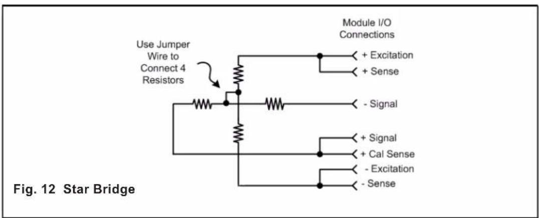
text_image
Use Jumper Wire to Connect 4 Resistors Module I/O Connections + Excitation + Sense - Signal + Signal + Cal Sense - Excitation - Sense Fig. 12 Star BridgeAPPENDIX E: Tested Load Manufacturers
TECHNICAL NOTES
Daytronic has tested the following load cell manufacturers for functionality with the TEDs interface of the 5T70 / 5T78 unit.
# 1 tecsis LP - WIKA www.tecsis.us
2 FUTEK www.futek.com
1

flowchart
graph LR
    A["5T70(V)"] -->|J1| B["TECSIS LP (WIKA) load cell"]
    A --> C["SHIELD"]
    A --> D["TEDS INPUT"]
    A --> E["+ EXCITATION"]
    A --> F["+ SENSE"]
    A --> G["- SENSE"]
    A --> H["- EXCITATION"]
    A --> I["CALIBRATION ENABLE"]
    A --> J["- SIGNAL"]
    A --> K["+ SIGNAL"]
    A --> L["CALIBRATION SENSE"]
    B --> M["PIN 1: + SIGNAL"]
    B --> N["PIN 2: + EXCITATION NO CONNECTION"]
    B --> O["PIN 3: + SENSE"]
    B --> P["PIN 4: TEDS DATA"]
    B --> Q["PIN 5: - SIGNAL"]
    B --> R["PIN 6: - EXCITATION"]
    B --> S["PIN 7: - SENSE"]
    B --> T["PIN 8: TEDS GND - SHIELD"]
    B --> U["PIN 9: - SHIELD"]
2 5T70(V)
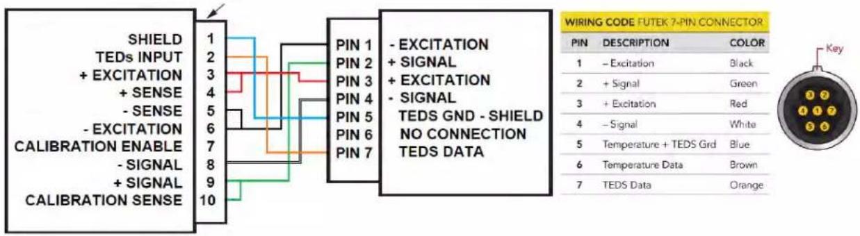
text_image
SHIELD TEDS INPUT + EXCITATION + SENSE - SENSE - EXCITATION CALIBRATION ENABLE - SIGNAL + SIGNAL CALIBRATION SENSE 1 2 3 4 5 6 7 8 9 10 PIN 1 PIN 2 PIN 3 PIN 4 PIN 5 PIN 6 PIN 7 - EXCITATION + SIGNAL + EXCITATION - SIGNAL TEDS GND - SHIELD NO CONNECTION TEDS DATA WIRING CODE FUTEK 7-PIN CONNECTOR PIN DESCRIPTION COLOR 1 - Excitation Black 2 + Signal Green 3 + Excitation Red 4 - Signal White 5 Temperature + TEDS Grd Blue 6 Temperature Data Brown 7 TEDS Data OrangeFUTEK load cell
Note: FUTEK normalizes their "zero" calibration point to an absolute "zero" offset point. When the TEDs download is accomplished and the sensor is installed, the user may establish a new zero point using the accompanied software configurator.
BLANK PAGE

DAYTRONIC
Daytronic Corporation