AA14-4F010 - Non spécifiée Daytronic - Free user manual and instructions
Find the device manual for free AA14-4F010 Daytronic in PDF.

User questions about AA14-4F010 Daytronic
0 question about this device. Answer the ones you know or ask your own.
Ask a new question about this device
Download the instructions for your Non spécifiée in PDF format for free! Find your manual AA14-4F010 - Daytronic and take your electronic device back in hand. On this page are published all the documents necessary for the use of your device. AA14-4F010 by Daytronic.
USER MANUAL AA14-4F010 Daytronic
The AA14-4F010 is a high-isolation, four-channel conditioner, accepting real-world temperature signals from Types E, J, K, N, R, S, and T Thermocouples. Based on NIST polynomials, linear output is produced over each thermocouple's stated operating range, and within the rated accuracy limits—without the need for additional output processing. See Table 1 for the "mV/degree" linear output produced by the AA14-4F010 for different TC types and ranges (°C or °F).
PLEASE NOTE: WHILE ALL FOUR CHANNELS OF A GIVEN AA14-4F010 CARD MUST BE DEDICATED TO THE SAME TC TYPE, INDIVIDUAL CARDS DEDICATED TO DIFFERENT TC TYPES MAY BE MIXED AS DESIRED WITHIN THE TOTAL DATA ACQUISITION SYSTEM. IT IS ALSO REQUIRED THAT THE AA14-4F010'S CHANNEL NO. 1 BE USED.
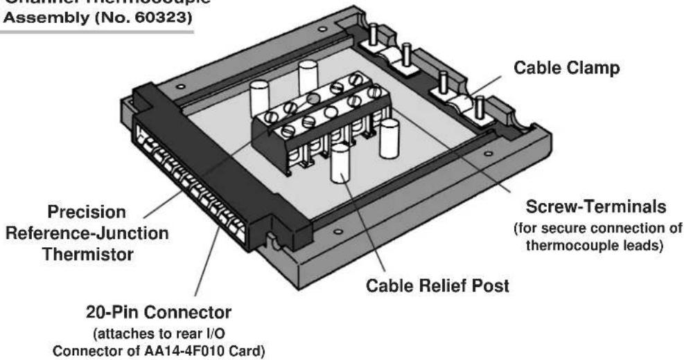
This conditioner features true galvanic isolation with pulse-width modulation, allowing sensor-to-chassis or sensor-to-sensor common-mode voltages as high as 1500 V (rms) to be accommodated. Internal reference-junction compensation is automatically selected by thermocouple choice. No external cold junction is required (although the user may supply his own Controlled Ambient Temperature Zone for reference-junction purposes, if desired). A conventional Daytronic four-channel isothermal connector assembly (No. 60323, shown in Figs. 2 and 3) is supplied with each Model AA14-4F010, with screw terminals for direct connection of TC leads (which cannot be soldered), and with a precision thermistor for measurement of the reference-junction temperature. The same connector may be used with any TC type.
In the event of a broken thermocouple wire or other “open TC” condition, the AA14-4F010 will automatically report an indeterminate off-scale reading for the TC channel in question, with positive or negative polarity selectable on a per-channel basis (as explained in Section 3.a).
Each AA14-4F010 input channel employs an active low-pass filter with a fixed cutoff frequency of 10 Hz. A nominal ±5-V ANALOG OUTPUT is produced by each active AA14-4F010 input channel, for purposes of real-time signal monitoring. Each of these "Auxiliary Outputs" is available on a corresponding mainframe wire-wrap pin. Each output may be individually set, if desired, to represent the prefiltered value of the corresponding input (see Section 3.b).
"Absolute" calibration lets you quickly set up each TC-based data channel simply by entering appropriate "type" and "range" information. During operation, appropriate reference-junction compensation, real-time digital linearization, and engineering-unit scaling are automatically applied for each type of thermocouple used. A second, two-point "zero and span" calibration technique is provided, however, for applications where it is desirable to force multiple TC readings to the same exactly known temperature.*
NOTE: Fig. 1 shows the stand-off circuit boards (or "tiles") that provide the analog filtering and galvanic isolation for an AA14-4F010 card's data channels. FILTER TILES (ONLY) MAY BE INSTALLED OR REMOVED BY THE USER, IN THE FIELD. CONTACT THE DAYTRONIC SERVICE DEPARTMENT FOR COMPLETE INSTRUCTIONS.
Fig. 1 Model AA14-4F010 Modular Card Components
I/O Connector
Four-Channel Isolator Tile
Fixed 10-Hz Filter (Chans. 3 & 4)
Fixed 10-Hz Filter (Chans. 1 & 2)
ADDITIONAL AA14-4F010 SPECIFICATIONS
Number of Input Channels: Four
Thermocouple Types and Ranges: See Table 1; automatically selected—on an individual channel basis—when the channel is configured; for System 10 channel "type" codes assigned to AA14-4F010 data channels, see Table 3 (Section 3.c)
Amplifier (per channel):
Normal-Mode Range: ±80 mV operating; ±240 V without instrument damage
Common-Mode Range: 1200 V (rms) operating and without instrument damage
Common-Mode Rejection Ratio: DC and at 60 Hz: -130 dB
Input Impedance: Differential: 10 MΩ; Common-Mode: 470 pF to earth
Offset: Initial: ±10 μV; vs. temperature: ±0.2 μV/°C; vs. time: ±0.5 μV/month
Gain Accuracy: ±0.05% of full scale
Gain Stability: vs. temperature: ±25 ppm/°C; vs. time: ±20 ppm/month
Filter (per channel): 3-pole modified Butterworth, 3 dB down at 10 Hz; 60 dB down at 195 Hz
Step-Response Settling Time (Full-Scale Output):
To 1% of final value: 70 msec
To 0.1% of final value: 85 msec
To 0.02% of final value: 95 msec
Auxiliary Outputs: Nominal ±5 V-DC signals available on mainframe wire-wrap pins*; individually jumper-selectable to represent either the filtered or prefiltered value of the channel (see Section 3.b)
Power-Supply Slot Allotment: Maximum consumption of supply current from the Conditioner Card Slot is 95 mA
Table 1 Thermocouple Ranges for the Model AA14-4F010
| TC Type Range Resolution* (mV/degree)** | ||
| E -200°C to +1000°C 0.1°C 5.0000 | ||
| E -328°F to +1832°F 0.1°F 2.7778 | ||
| J -200°C to +1200°C 0.1°C 4.0000 | ||
| J -328°F to +2192°F 0.1°F 2.2222 | ||
| K -200°C to +1372°C 0.1°C 4.0000 | ||
| K | -328°F to +2501.6°F | 0.1°F 2.2222 |
| N | -180°C to +1300°C 0.1°C 4.0000 | |
| N | -292°F to +2372°F 0.1°F 2.2222 | |
| R -50°C to +1768°C | 0.1°C 2.0000 | |
| R -58°F to +3214.4°F | 0.1°F 1.1111 | |
| S -50°C to +1768°C | 0.1°C 2.0000 | |
| S -58°F to +3214.4°F | 0.1°F 1.1111 | |
| T | -200°C to +400°C | 0.1°C 5.0000 |
| T -328°F to +752°F | 0.1°F 2.7778 | |
2 TRANSDUCER CONNECTIONS
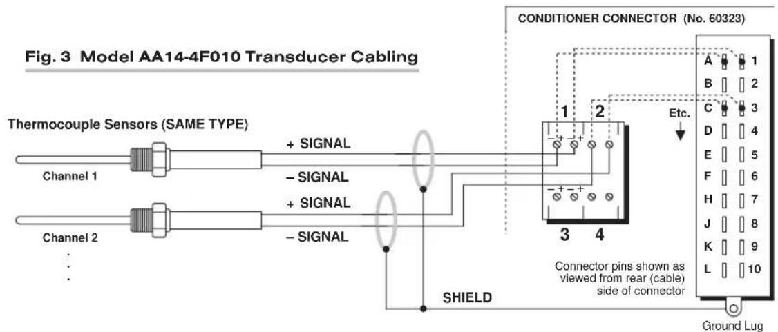
The Model AA14-4F010's I/O CONNECTOR mates with Daytronic CONDITIONER CONNECTOR No. 60323, shown in Fig. 2. This connector contains four “±” screw-terminal pairs, one for each TC sensor. TC leads should be directly attached to the corresponding screw terminals (they should never be soldered). As shown in Fig. 3, each screw terminal connects internally to a specific pin on the AA14-4F010's rear 20-pin I/O CONNECTOR. Table 2 gives standard pin assignments for the I/O connector.
Since reference-junction compensation is provided by the dual-bead thermistor embedded in the Conditioner Connector, no external cold junction is required.
IMPORTANT: UNUSED THERMOCOUPLE INPUT CHANNELS should be shorted together as shown in Fig. 4, to prevent possible crosstalk from the "OPEN TC" detection circuit into working TC channels.
Table 2 Model AA14-4F010 Pin Assignments
| I/O Connector Pin Number | Screw Terminal | Conditioner Channel Number | Conditioner Line Function |
| 1 | 1(+) | 1 | +SIGNAL |
| A | 1(-) | 1 | -SIGNAL |
| 2 | Not Committed | ||
| B | Not Committed | ||
| 3 | 3(+) | 2 | +SIGNAL |
| C | 3(-) 2 | -SIGNAL | |
| 4 | Not Committed | ||
| D | Not Committed | ||
| (cont'd) | |||
* For certain restricted ranges, a resolution of 0.01^ or F may be achieved. See Table 3, Section 3.c.
** See "Auxiliary Outputs," above.
Fig. 2 Four-Channel Thermocouple Connector Assembly (No. 60323)
text_image
Channel Thermocouple Assembly (No. 60323) Cable Clamp Precision Reference-Junction Thermistor Screw-Terminals (for secure connection of thermocouple leads) 20-Pin Connector (attaches to rear I/O Connector of AA14-4F010 Card) Cable Relief PostI/O Connector Conditioner Conditioner Pin Screw Channel Line Number Terminal Number Function
| 5 | 5(+) | 3 | +SIGNAL |
| E | 5(-) 3 | -SIGNAL | |
| 6 | Not Committed | ||
| F | Not Committed | ||
| 7 | 7(+) | 4 | +SIGNAL |
| H | 7(-) 4 | -SIGNAL | |
| 8 | Not Committed | ||
| J | Not Committed | ||
| 9 INTERNAL | THERMISTOR: T1 | ||
| K,L | USE | THERMISTOR: GROUND (COMMON) | |
| 10 | ONLY | THERMISTOR: T2 | |
3
SETUP AND/OR OPERATING CONSIDERATIONS
3.a SELECTION OF "OPEN TC" POLARITY
In the event of a broken thermocouple wire or other "open TC" condition, the Model AA14-4F010 will automatically report an indeterminate off-scale reading for the TC channel in question. The conditioner is normally preset at the factory for positive off-scale "open TC" indication for each channel. However, you may easily reset any channel for negative off-scale "open TC" indication, as follows:
- Remove the AA14-4F010 card from its mainframe slot. For "Card Insertion and Removal," see Manual Section 1.B. Since the AA14-4F010 is "hot-pluggable," you need NOT turn off mainframe power before removing the card.
- Refer to Fig. 5, below, and locate the OPEN TC POLARITY PROGRAMMING JUMPER PINS on the top side of the Isolator Tile. One "minijumper" is provided for each channel's set of three jumper pins.
text_image
Fig. 3 Model AA14-4F010 Transducer Cabling Thermocouple Sensors (SAME TYPE) Channel 1 Channel 2 + - + SIGNAL - + SIGNAL - - SIGNAL SHIELD CONDITIONER CONNECTOR (No. 60323) A 1 B 2 C 3 D 4 E 5 F 6 H 7 J 8 K 9 L 10 Etc. Connector pins shown as viewed from rear (cable) side of connector Ground Lug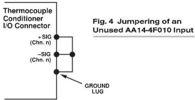
text_image
Thermocouple Conditioner I/O Connector +SIG (Chn. n) -SIG (Chn. n) GROUND LUG Fig. 4 Jumpering of an Unused AA14-4F010 InputFig. 5 Model AA14-4F010 Programming Jumper Pins
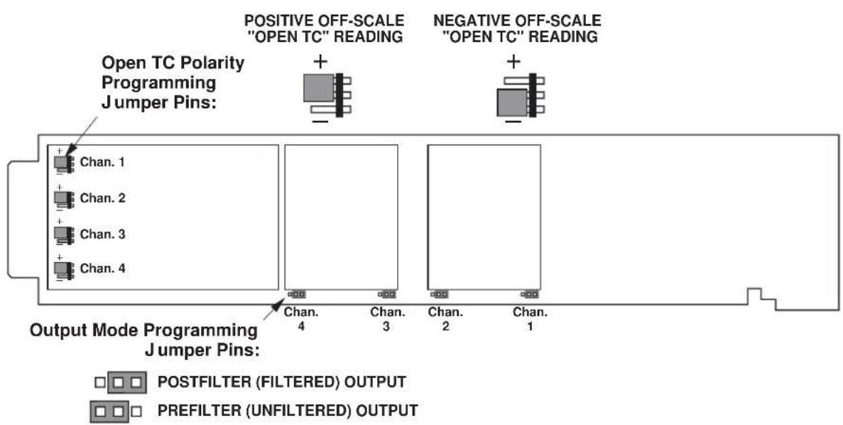
text_image
Open TC Polarity Programming Jumper Pins: Positive OFF-SCALE "OPEN TC" READING NEGATIVE OFF-SCALE "OPEN TC" READING Output Mode Programming Jumper Pins: POSTFILTER (FILTERED) OUTPUT PREFILTER (UNFILTERED) OUTPUT- Position the jumper for each channel as shown in Fig. 5 to interconnect the pair of pins corresponding to the desired "open TC" polarity for that channel. You will need to use a small pair of needle-nosed pliers to move the jumper.
- Reinsert the AA14-4F010 card in its mainframe slot.
3.b SELECTION OF ANALOG OUTPUT MODES
As mentioned in Section 1, each AA14-4F010 channel's ±5-V ANALOG OUTPUT can be set to represent either the filtered or prefiltered reading of that channel. To set the output mode for each of your AA14-4F010's active input channels, ^* you should
- Remove the AA14-4F010 card from its slot (see Section 3.a, Step 1, above).
- Refer to Fig. 5 and locate the OUTPUT MODE PROGRAMMING JUMPER PINS beneath the AA14-4F010's Filter Tile(s). One "minijumper" is provided for each channel's set of three jumper pins.
- Position the jumper for each channel as shown in Fig. 5 to interconnect the pair of pins that corresponds to the desired output mode for that channel. You will need to use a small pair of needle-nosed pliers to move the jumper.
- Reinsert the AA14-4F010 card in its mainframe slot.
3.c CONFIGURATION AND CALIBRATION
For initial configuration of ANALOG INPUT CHANNELS dedicated to a specific Model AA14-4F010 card, see the general remarks on System 10 "real-channel" configuration in Manual Section 1.G.1 and elsewhere in the System 10 Guidebook. For AA14-4F010 channel "type" codes, see Table 3, below.
In System 10, the initial configuration and ABSOLUTE CALIBRATION of an AA14-4F010 channel (No. "x") involve direct entry of the channel's TYPE CODE, SCALING FACTOR ("m" coefficient), and ZERO OFFSET ("b" term) via the corresponding mnemonic commands. The values of these parameters that are entered will depend on the TC type and the desired engineering units (°C or °F), as given in Table 3, below. You may also perform a subsequent TWO-POINT (DEADWEIGHT) calibration of an AA14-4F010 channel in System 10, as explained below.
ABSOLUTE CALIBRATION
In the following procedure, Channel No. "x" is a System 10 "REAL CHANNEL" sourced by an AA14-4F010 card. Note that, with the exception of the LOCATE (LCT) command (Step 2), each of the commands can be applied to a continuous range of channels by entering the command in "range" form, where the single channel-number argument "x" is replaced by "x TO y" (indicating all channels from Channel No. x to and including Channel No. y).
- Turn ON the system EEPROM SWITCH.
- Make sure that Channel No. x has been assigned the proper A-SLOT / SUBCHANNEL "location." See Manual Section 1.G.1 for details on the LOCATE (LCT) command.
* The output mode setting for an UNUSED channel is immaterial, and will not affect operation of the AA14-4F010.
- Apply a RESET (RST) command to Channel No. x:
RST x [CR]
The channel will be retyped as "55" (i.e., a direct millivolt reading from the system's internal Called Signal Bus). Its SCALING FACTOR ("m") will be changed to "5000" and its ZERO OFFSET ("b") to "0." Its current "location" (LCT) assignment will not be affected.
- Apply the following commands to Channel No. x, using the values of "v," "m," and "b" given in Table 3 for the channel's specific TC type and range:
$$ \text { TYP } x = v [ \text { CR } ] $$
$$ \mathbf {E M M} \mathbf {x} = \mathbf {m} [ \mathbf {C R} ] $$
$$ \mathbf {B E E} \mathbf {x} = \mathbf {b} [ \mathbf {C R} ] $$
Be sure to enter the "m" value as shown (with a "0" or "00" after the decimal point), if you want your final measurement to be in tenths or hundredths of a degree, respectively.
Table 3 Calibration Values for an AA14-4F010 Channel
| Type Code Scaling Factor Zero Offset | ||||
| TC Type Range & Resolution ("v") ("m") ("b") | ||||
| E -200.0°C to +1000.0°C 41 1000.0 | 0.0* | |||
| E -200.00°C to +250.00°C | 67 | 250.00 | 0.00* | |
| E -328.0°F to +1832.0°F | 41 | 1800.0 | 32.0 | |
| J -200.0°C to +1200.0°C 42 1250.0 | 0.0* | |||
| J -200.00°C to +250.00°C | 64 | 312.50 | 0.00* | |
| J -328.0°F to +2192.0°F | 42 | 2250.0 | 32.0 | |
| K -200.0°C to +1372.0°C 43 1250.0 | 0.0* | |||
| K -200.00°C to +250.00°C | 61 | 312.50 | 0.00* | |
| K -328.0°F to +2501.6°F | 43 | 2250.0 | 32.0 | |
| N -180.0°C to +1300.0°C 44 1250.0 | 0.0* | |||
| N -292.0°F to +2372.0°F | 44 | 2250.0 | 32.0 | |
| R -50.0°C to +1768.0°C | 45 | 2500.0 | 0.0* | |
| R -58.0°F to +3214.4°F | 45 | 2250.0 | 32.0 | |
| S -50.0°C to +1768.0°C | 46 | 2500.0 | 0.0* | |
| S -58.0°F to +3214.4°F | 46 | 2250.0 | 32.0 | |
| T -200.0°C to +400.0°C | 47 | 1000.0 | 0.0* | |
| T -328.0°F to +752.0°F | 47 | 1800.0 | 32.0 | |
- Use the FILTER (FIL) command to apply to Channel No. x a level of digital smoothing that is appropriate to your application:
FIL x = f [CR]
The integer “f” should be 1, 2, or 3 for a TC range with tenth-of-a-degree resolution, and a number from 4 through 9 for a range with hundredth-of-a-degree resolution (see Manual Section 2.G for a complete explanation of the FIL command).
- Turn OFF the system EEPROM SWITCH.
Two-Point (Deadweight) Calibration
Using the standard ZERO (ZRO) and FORCE (FRC) commands, this conventional "zero and span" method can be easily applied to an AA14-4F010 channel on a real-time basis, to improve the ABSOLUTE calibration of an input when independently and accurately known temperature references are available (preferably the high and low extremes to which the sensor will be subjected). The mainframe's EEPROM Write Protect Switch must be ON for these commands to be effective. See Manual Section 1.G.5 for a general discussion of this conventional "zero and span" calibration technique.
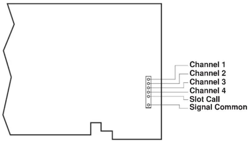
4 DIAGNOSTIC WIRE-WRAP PINS
As a special diagnostic and service tool, the five pins shown in Fig. 6 are directly accessible from the front of an installed AA14-4F010 card. These pins allow voltmeter or oscilloscope observation of data-channel output signals. THEIR USE IS INTENDED PRIMARILY FOR TRAINED SERVICE TECHNICIANS. With regard to the on-board diagnostic pins, please note the following:
- PROPER ESD PRACTICE SHOULD BE OBSERVED WHEN MAKING CONTACT WITH AN AA14-4F010 BOARD INSTALLED IN A "LIVE" DAYTRONIC SYSTEM MAINFRAME. ALWAYS GROUND YOURSELF TO THE MAINFRAME CHASSIS BEFORE TOUCHING THE BOARD.
- THE ANALOG SIGNAL PRESENT AT EACH ACTIVE "CHANNEL" PIN REPRESENTS EIGHT TENTHS (0.8) OF THAT CHANNEL'S NOMINAL CALL-BUS VOLTAGE. For a channel delivering a standard full-scale (+5-V) output, the corresponding diagnostic pin will therefore register +4 V.
- THE ANALOG SIGNAL PRESENT AT EACH ACTIVE "CHANNEL" PIN REPRESENTS THE FILTERED CHANNEL OUTPUT, AND IS NOT AFFECTED BY THE ANALOG OUTPUT MODE CURRENTLY SELECTED FOR THAT CHANNEL (see Section 3.b).
- THE "SLOT CALL" PIN DELIVERS A LOGIC SIGNAL THAT MAY BE USED TO SYNCHRONIZE AN OSCILLOSCOPE FOR TIMING ANALYSIS OF THE AA14-4F010 CARD.
Fig. 6 Diagnostic Wire-Wrap Pins