3170G - Measurement Daytronic - Free user manual and instructions
Find the device manual for free 3170G Daytronic in PDF.

User questions about 3170G Daytronic
0 question about this device. Answer the ones you know or ask your own.
Ask a new question about this device
Download the instructions for your Measurement in PDF format for free! Find your manual 3170G - Daytronic and take your electronic device back in hand. On this page are published all the documents necessary for the use of your device. 3170G by Daytronic.
USER MANUAL 3170G Daytronic
Copyright © 1996, Daytronic Corporation. All rights reserved.
No part of this document may be reprinted, reproduced, or used in any form or by any electronic, mechanical, or other means, including photocopying and recording, or in any information storage and retrieval system, without permission in writing from Daytronic Corporation. All specifications are subject to change without notice.
Correction
to Model 3170 Instruction Manual, v. SB.5.1
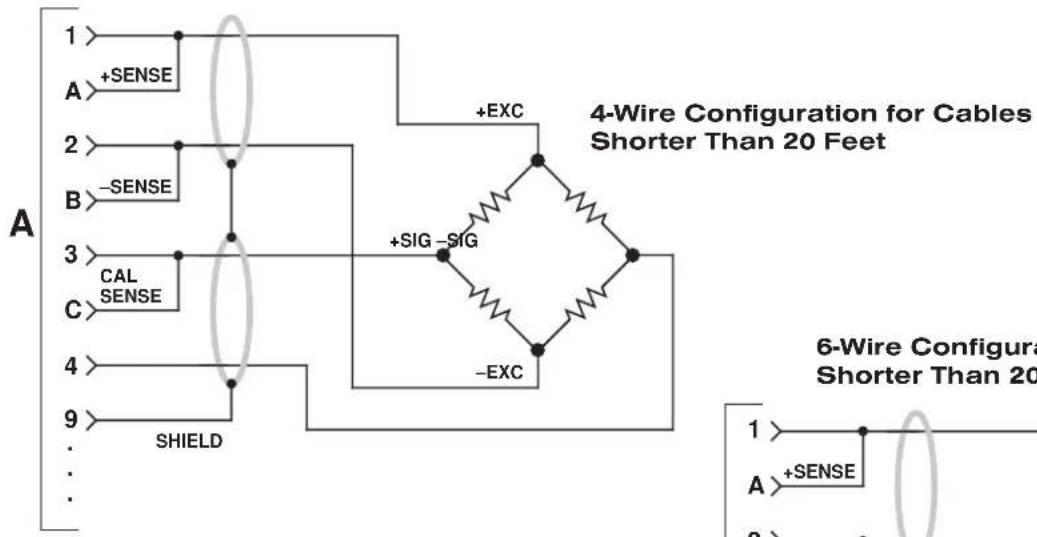
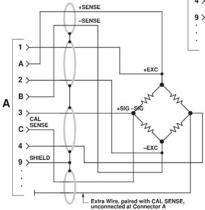
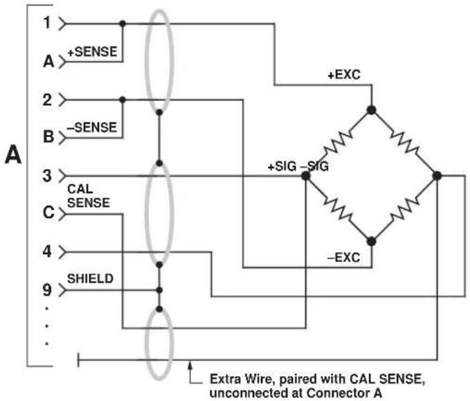
The I/O Wiring Data in Fig. 4 of this manual does not give the correct shield pairing of cable wires, which is shown in the revised diagrams below and on the following page:

(cont'd)
Correction
to Model 3170 Instruction Manual, v. SB.5.1 (cont'd)
Daytronic 3X70 Instrument to Generalized Strain Gage Transducer
text_image
A 1 +SENSE 2 -SENSE 3 CAL SENSE 4 SHIELD 9 + EXC 4-Wire Configuration for Cables Shorter Than 20 Feet +SIG -SIG -EXC 6-Wire Configura Shorter Than 20 Feet 1 A +SENSE 28-Wire Configuration for Cables Longer Than 20 Feet
flowchart
graph TD
    A["1"] --> B["2"]
    B --> C["3"]
    C --> D["4"]
    D --> E["9"]
    E --> F["..."]
    F --> G["..."]
    G --> H["..."]
    H --> I["..."]
    I --> J["..."]
    J --> K["..."]
    K --> L["..."]
    L --> M["..."]
    M --> N["..."]
    N --> O["..."]
    O --> P["..."]
    P --> Q["..."]
    Q --> R["..."]
    R --> S["..."]
    S --> T["..."]
    T --> U["..."]
    U --> V["..."]
    V --> W["..."]
    W --> X["..."]
    X --> Y["..."]
    Y --> Z["..."]
    Z --> AA["..."]
    AA --> AB["..."]
    AB --> AC["..."]
    AC --> AD["..."]
    AD --> AE["..."]
    AE --> AF["..."]
    AF --> AG["..."]
    AG --> AH["..."]
    AH --> AI["..."]
    AI --> AJ["..."]
    AJ --> AK["..."]
    AK --> AL["..."]
    AL --> AM["..."]
    AM --> AN["..."]
    AN --> AO["..."]
    AO --> AP["..."]
    AP --> AQ["..."]
    AQ --> AR["..."]
    AR --> AS["..."]
    AS --> AT["..."]
    AT --> AU["..."]
    AU --> AV["..."]
    AV --> AW["..."]
    AW --> AX["..."]
    AX --> AY["..."]
    AY --> AZ["..."]
    AZ --> BA["..."]
    BA --> BB["..."]
    BB --> BC["..."]
    BC --> BD["..."]
    BD --> BE["..."]
    BE --> BF["..."]
    BF --> BG["..."]
    BG --> BH["..."]
    BH --> BI["..."]
    BI --> BJ["..."]
    BJ --> BK["..."]
    BK --> BL["..."]
    BL --> BM["..."]
    BM --> BN["..."]
    BN --> BO["..."]
    BO --> BP["..."]
    BP --> BQ["..."]
    BQ --> BR["..."]
    BR --> BS["..."]
    BS --> BT["..."]
    BT --> BU["..."]
    BU --> BV["..."]
    BV --> BW["..."]
    BW --> BX["..."]
    BX --> BY["..."]
    BY --> BZ["..."]
    BZ --> CA["..."]
    CA --> CB["..."]
    CB --> CC["..."]
    CC --> CD["..."]
    CD --> CE["..."]
    CE --> CF["..."]
    CF --> CG["..."]
    CG --> CH["..."]
    CH --> CI["..."]
    CI --> CJ["..."]
    CJ --> CK["..."]
    CK --> CR["..."]
    CR --> CS["..."]
    CS --> CT["..."]
    CT --> CU["..."]
    CU --> CV["..."]
    CV --> CW["..."]
    CW --> CX["..."]
    CX --> CY["..."]
    CY --> CZ["..."]
    CZ --> DA["..."]
    DA --> DB["..."]
6-Wire Configuration for Cables Shorter Than 20 Feet
flowchart
graph TD
    A["Input A"] -->|+SENSE| B["Resistor"]
    A -->|-SENSE| B
    B -->|CAL SENSE| C["Output C"]
    B -->|-EXC| D["Output D"]
    C --> E["SHIELD"]
    D --> F["Extra Wire, paired with CAL SENSE, unconnected at Connector A"]
MODEL
3170
STRAIN GAGE CONDITIONER
INSTRUCTION MANUAL
Daytronic Corporation
TABLE OF CONTENTS
Section Page
1 Description 1
2 Installation and Cabling 3
3 Calibration 8
4 Block Diagram Description 12
5 Verification of Normal Operation 14
LIST OF ILLUSTRATIONS
Figure Page
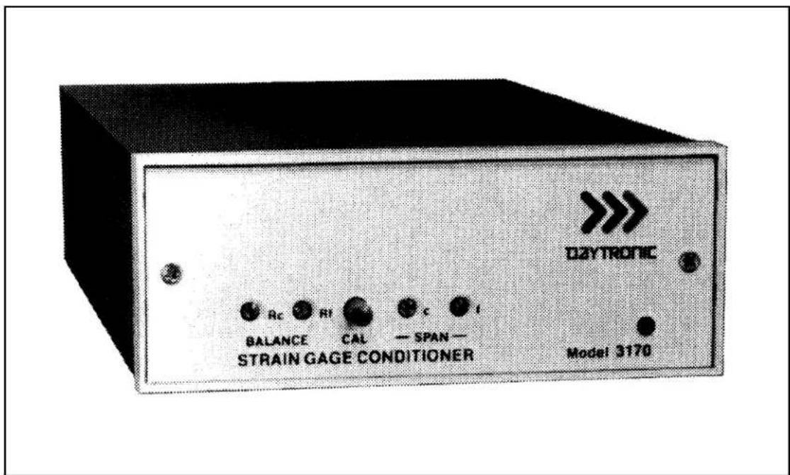
1 Model 3170 Strain Gage Conditioner .... 1
2 Instrument Mounting Dimensions 4
3 Instrument Panel Mounting 5
4 I/O Wiring Data 9
5 Front-Panel Description 11
6 Block Diagram 15
7 Star-Bridge Construction 17
LIST OF TABLES
Table Page 1 Specifications 2
PLEASE NOTE: Sections 6 and 7, Figures 8 and 9, and Table 2 have been removed from this manual.
If you need information regarding specific 3170 components and circuitry, please contact the Daytronic Service Department at (937) 293-2566.
INSTRUCTION MANUAL MODEL 3170 STRAIN GAGE CONDITIONER
1. DESCRIPTION
The Model 3170 conditioner-amplifier module for use with resistance strain gage transducers. It supplies a regulated dc excitation voltage to the transducer bridge, provides the necessary balancing and calibration controls, and amplifies the resulting signal to a standard Five-Volt Data Signal Level which is the output analog signal level of 3000 Series Modules. The 3170 has three separate analog outputs, each having a different bandpass: (1) dc to 2 kHz, (2) dc to 200 Hz, and (3) dc to 2 Hz. Active low-pass filters are used to achieve the 200 Hz and 2 Hz cutoff frequencies. The filtered outputs provide for averaging or smoothing signals containing noise or other unwanted dynamic components which are periodic in nature. Filtering removes these dynamic components so that stable digital indication and precise, jitter-free control action can be obtained. The Model 3170 is shown in Figure 1 and the specifications are given in Table 1.
text_image
D2YTRONIC BALANCE CAL SPAN — STRAIN GAGE CONDITIONER Model 3170Figure 1. Model 3170 Strain Gage Conditioner
Table 1. Specifications
Transducers: 4-arm bridges, 90 to 2000 ohms, nominally 1 to 8 mv/v, full scale (120 ohms or less requires use of 5-volt excitation).
Cables: 4-, 5-, or 7-wire, depending on application; 1000 feet maximum length.
Bridge Excitation: Regulated 5 volts or 10 volts dc, selected with I/O connector wiring. Transducers with sensitivity from 4 to 8 mv/v full scale must use 5-volt excitation.
Balance Adjustments: 10-turn coarse and fine; will balance 1.5 mv/v initial unbalance.
Span Adjustments: 10-turn coarse and fine; 1 to 8 mv/v, full scale.
Analog Outputs: Three analog outputs available; 0 to ±5 volts with 50% overange, 5 milliamperes maximum. Bandpass is dc to 2 kHz, dc to 200 Hz, or dc to 2 Hz, depending on output used. Active low-pass filters provide for rolloff of 60 dB per decade above cutoff frequency. Full-scale slew time is 1.4/f seconds, where f isthe cutoff frequency.
Common Mode Rejection: Greater than 80 dB.
Output Ripple and Noise: 0.15% of full scale (rms) maximum for 2-kHz and 100-Hz outputs; 0.02% of full scale (rms) on 2-Hz output.
Accuracy: 0.05% of full scale.
Dimensions: 1.7 x 4.41 x 8.5 (HWD inches).
Operating Temperature Range: 0 to +130 degrees F.
Power Requirements: 105 to 135 volts ac, 50 to 400 Hz at 5 watts maximum.
Daytronic Corporation
Remote sensing techniques are used to regulate the excitation voltage at the transducer. Either a 10-volt or a 5-volt excitation voltage can be selected by appropriate wiring at the module I/O connector. The excitation voltage is protected against overloads and accidental short circuits.
The 3170 uses a CMOS chopper-stabilized differential signal amplifier which has over 100-megohms input impedance per input line. This circuit guarantees negligible drift with temperature variations or component aging.
Calibration of the 3170 is accomplished by the conventional shunt technique, using an internally installed calibration resistor. A front-panel CAL button or Remote Cal terminals on the module I/O connector can be used to initiate the calibration procedure.
The 3170 Strain Gage Conditioner is also available in two additional forms. The Model 3270 includes the addition of a digital indicator to view the analog output of the conditioner. The Model 3370 includes a Limit section (in addition to a digital indicator) which provides high, low, and ok indications and outputs. The digital indicator and limit options are standard to all 3000 Modules and are covered in separate instruction manuals.
2. INSTALLATION AND CABLING
The following paragraphs provide the instructions for module installation and cabling.
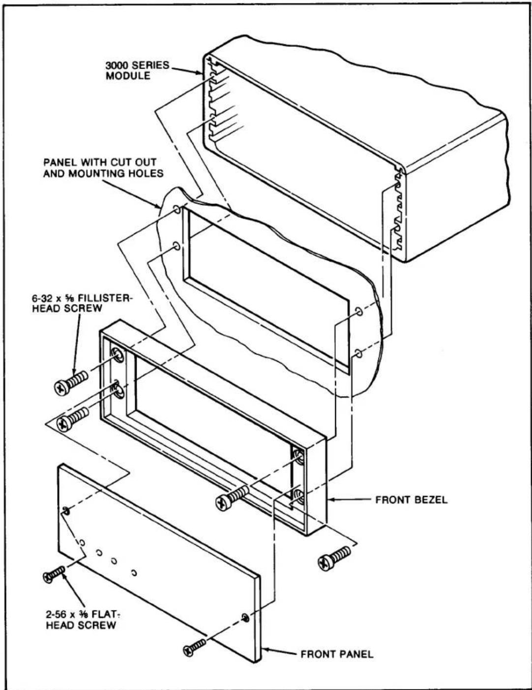
Module Mounting. The 3000 Series Modules can be operated as bench-top instruments or they can be rack- or panel-mounted. Clearance dimensions for a bench-mounted instrument are given in Figure 2. Panel cut-out dimensions for panel mounting are also shown in Figure 2. Up to four 3000 Series instruments can be mounted in a 19-inch rack using the 1.75-inch high Model 3004 Rack Adaptor. Rack-mounting dimensions are also given in Figure 2. To panel mount an instrument, proceed as follows. Refer to Figure 3.
Important: The unit is shipped with two spacer washers on the securing screws of the rear-panel I/O Connector. When panel-mounting the unit, you MUST REMOVE THESE WASHERS, so that the printed-circuit board may move forward about 1/8" during Step (f).
(a) Remove the front panel by removing the two 2-56 x 3/8 flat-head screws.
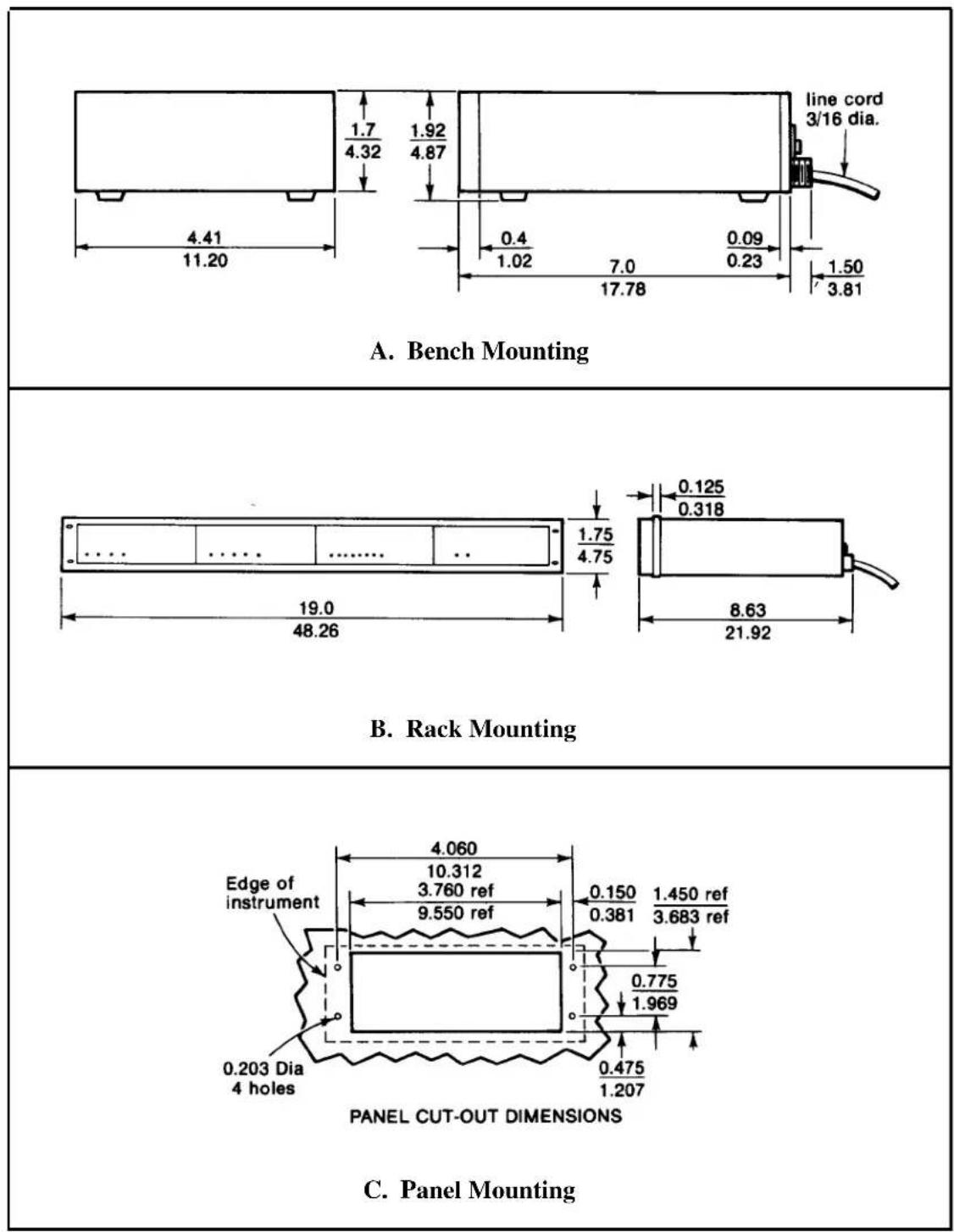
Figure 2. Instrument Mounting Dimensions
text_image
3000 SERIES MODULE PANEL WITH CUT OUT AND MOUNTING HOLES 6-32 x 5/8 FILLISTER- HEAD SCREW FRONT BEZEL 2-56 x 3/8 FLAT- HEAD SCREW FRONT PANELFigure 3. Instrument Panel Mounting
Model 3170
(b) Remove the front bezel by removing the four 6-32 x 5/8 fillister-head screws.
(c) Make the panel cutout and drill the screw clearance holes indicated in Figure 2. The front bezel can be used as a template to define the rectangular cutout and locate the clearance holes.
(d) Hold the module enclosure behind the panel and reattach the front bezel to the enclosure from the front of the panel with the four mounting screws.
(e) Reinstall the front panel.
(f) Tighten the two securing screws of the rear-panel module I/O connector to insure that the connector is seated and that the module printed-circuit board is pushed fully forward so that the front-panel screwdriver adjustments and buttons are accessible. These screws give approximately 1/8-inch of adjustment; consequently, this is the maximum panel width which should be used.
CAUTION
Do not overtighten the connector securing screws or resultant damage may occur to the printed-circuit board.
AC Power Connection. To protect operating personnel, the 3000 Series Modules are equipped with a three-conductor power cord. When the cord is plugged into the appropriate receptacle, the instrument is grounded. The offset pin on the power cord is ground. To maintain the safety ground when operating the module from a two-contact outlet, use a three-prong to two-prong adaptor and connect the green pigtail on the adaptor to ground.
To prepare the module for operation, connect the power cable to a 105-135 volt ac, 50-400 Hz power source. The instrument can use up to 5 watts of power.
Calibration Resistor. If a fixed resistor is shunted across one arm of a strain gage bridge, it produces an unbalance equivalent to that of a particular value of mechanical input. If this Equivalent Input value is accurately known, it can be used as a reference point for shunt calibration of the system. Upon completion of installation of the transducer and its associated cabling, the user can:
Daytronic Corporation
(1) Perform an overall dead weight calibration using a precisely known value of mechanical input. The calibration can then be transferred to the installed shunt calibration resistor for convenience in subsequent checking.
(2) Replace the installed calibration resistor with one (or an equivalent resistance value) supplied by the transducer manufacturer to achieve a precisely known Equivalent Input, allowing the instrument sensitivity to be adjusted correctly.
(3) Determine the Equivalent Input value for the installed calibration resistor, knowing the transducer sensitivity, and adjust the instrument sensitivity accordingly.
A precision 59-kilohm calibration resistor is installed in the 3170 at the factory. The installed resistor can usually be used even though the transducer calibration data mentions some other resistance value. In Section 3 of this manual, the techniques described above are demonstrated. If, however, the installed value of calibration resistor is not appropriate, the 59-kilohm resistor should be replaced at this time by one that is appropriate for the transducer and measurement range to be used. The calibration resistor is mounted on terminals located at the front edge of the strain gage conditioner printed-circuit board. It can be accessed by removing the module front panel.
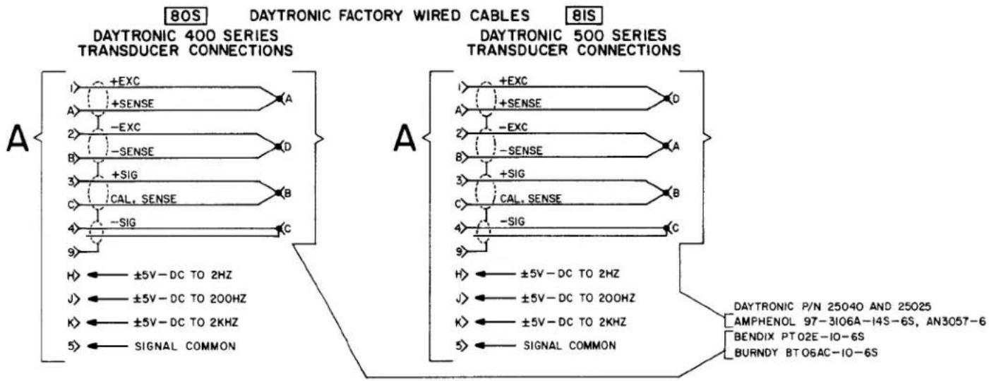
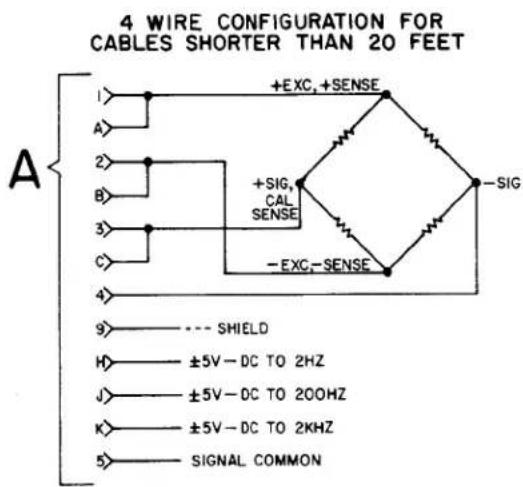
Transducer Cabling. Cabling to the transducer is accomplished via the supplied module I/O connector. The I/O connector pin numbers and functions are given in Figure 4. When Daytronic 400 or 500 Series Transducers are used, factory-wired cables are available as shown in Figure 4. When user-fabricated transducer cabling is used, it should take the form of either the 4-, 5-, or 7-wire cable configuration shown in Figure 4.
The 4-wire configuration should be used when overall dead weight calibration is the method used and the required cable length is less than 20 feet. The 5-wire configuration should be used when the instrument is to be calibrated by achieving a precisely known Equivalent Input value through the use of a shunt calibration resistor (or resistance value) supplied by the transducer manufacturer and when the required cable length is less than 20 feet. The 7-wire configuration should be used with cable lengths longer than 20 feet since the excitation voltage is sensed and regulated at the transducer and optimum shunt calibration can be achieved.
Model 3170
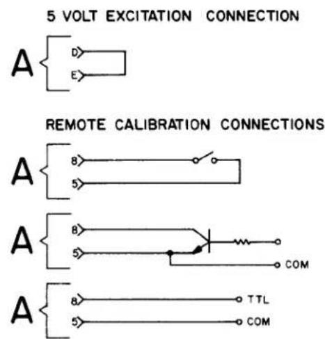
Transducer Excitation. Either 5-volt or 10-volt bridge excitation can be selected. In general, 5-volt excitation is used with 120-ohm transducers, and the 10-volt excitation is used with 350-ohm devices. However, for any transducer which has a 4 mv/v or higher sensitivity, 5-volt excitation must be used to maintain proper operation without saturating the conditioner amplifiers. Five-volt excitation is selected by shorting pins D and E of the module I/O connector (see Figure 4). Ten-volt excitation is achieved when pins D and E are not connected together.
Remote Calibration Check. The instrument can be remotely placed in the calibration mode by shorting pins 5 (Signal Common) and 8 (Remote Cal) of the module I/O connector. Figure 4 indicates three methods of remotely entering the calibration mode through the use of an external switch, transistor, or TTL source. The Remote Cal function provides a convenient method for periodically monitoring calibration of the instrument.
Analog Outputs. Three different analog outputs are available at the module I/O connector. Each output has a different passband: dc to 2 kHz, dc to 200 Hz, and dc to 2 Hz. The 200 and 7 Hz cutoff frequencies are achieved with active low-pass filters. As the cutoff frequency is lowered, a trade off is made between noise elimination and increased time-to-answer or slew time. Each output has a 60-dB rnlloff a decade from the cutoff frequency. The filter characteristics are given by the following equations.
$$ \begin{array}{l} \mathrm{A} _ {\text {out}} @ \mathrm{f} _ {0} = 0. 7 \mathrm{A} _ {\text {in}} \ \mathrm{A} _ {\text {out}} @ 1 0 \mathrm{f} _ {0} = 0. 0 0 1 \mathrm{A} _ {\text {in}} \ \mathrm{T} = 1. 4 / \mathrm{f} _ {0} \ \mathrm{A} _ {\text { in }} = \text { input amplitude } \ \mathrm{f} _ {0} = \text { selected cutoff frequency } \ \end{array} $$
where A_out = output amplitude
T = time-to-answer in seconds (output of filter within 0.1% of final value after step function is applied).
3. CALIBRATION
This section contains the instructions for calibrating the 3170 Included is a functional description of the module front panel (see Figure 5). To perform calibration, proceed as follows.
(a) Turn power ON by placing the rear-panel slide switch in the ON position. The front-panel indicator should light to indicate the application of
Figure 4 I/O Wiring Data
A
DAYTRONIC 3X70 INSTRUMENT I/O CONNECTOR W/PIN DESIGNATIONS (X=1,2,or 3,e.g.3170,3270,or 3370)

AMPHENOL 225-21021-103
REARVIEW
PIN
PIN
1 +EXCITATION
A +SENSE
2 -EXCITATION
B -SENSE
3 + SIGNAL INPUT
C CALIBRATION SENSE
4 - SIGNAL INPUT
D ← CONNECT FOR
5 SIGNAL COMMON
E ← 5V EXCITATION
6 NC
F NC
7 NC
H ANALOG OUTPUT, ±5V-DC TO 2HZ
8 REMOTE CALIBRATION
J ANALOG OUTPUT, ±5V-DC TO 200HZ
9 SHIELD
K ANALOG OUTPUT, ±5V-DC TO 2KHZ
IO OUTPUT SIGNAL COMMON
L NC
flowchart
graph TD
    subgraph DAYTRONIC_400_SERIES_TRANSUCER_CONNECTIONS
        A1["+EXC"] --> A2["A"]
        A2 --> A3["A"]
        A3 --> A4["-EXC"]
        A4 --> A5["B"]
        A5 --> A6["D"]
        A6 --> A7["+SIG"]
        A7 --> A8["B"]
        A8 --> A9["C"]
        A9 --> A10["-SIG"]
        A10 --> A11["C"]
        A11 --> A12["±5V-DC TO 2HZ"]
        A12 --> A13["J"]
        A13 --> A14["±5V-DC TO 200HZ"]
        A14 --> A15["K"]
        A15 --> A16["±5V-DC TO 2KHZ"]
        A16 --> A17["+SIG"]
    end
    subgraph DAYTRONIC_500_SERIES_TRANSUCER_CONNECTIONS
        B1["+EXC"] --> B2["A"]
        B2 --> B3["A"]
        B3 --> B4["-EXC"]
        B4 --> B5["B"]
        B5 --> B6["+SIG"]
        B6 --> B7["C"]
        B7 --> B8["SIGNAL SENSE"]
        B8 --> B9["-SIG"]
        B9 --> B10["C"]
        B10 --> B11["H"]
        B11 --> B12["±5V-DC TO 2HZ"]
        B12 --> B13["J"]
        B13 --> B14["±5V-DC TO 200HZ"]
        B14 --> B15["K"]
        B15 --> B16["±5V-DC TO 2KHZ"]
        B16 --> B17["SIGNAL COMMON"]
    end
    subgraph DAYTRONIC_Factory_WIRED_CABLES
        C1["+EXC"] --> C2["A"]
        C2 --> C3["A"]
        C3 --> C4["-EXC"]
        C4 --> C5["B"]
        C5 --> C6["+SIG"]
        C6 --> C7["C"]
        C7 --> C8["SIGNAL SENSE"]
        C8 --> C9["-SIG"]
        C9 --> C10["H"]
        C10 --> C11["SIGNAL COMMON"]
        C11 --> C12["±5V-DC TO 2HZ"]
        C12 --> C13["J"]
        C13 --> C14["±5V-DC TO 200HZ"]
        C14 --> C15["K"]
        C15 --> C16["±5V-DC TO 2KHZ"]
        C16 --> C17["SIGNAL COMMON"]
    end
    subgraph DAYTRONIC_500_SERIES_TRANSUCER_CONNECTIONS
        D1["+EXC"] --> D2["A"]
        D2 --> D3["A"]
        D3 --> D4["-EXC"]
        D4 --> D5["B"]
        D5 --> D6["+SIG"]
        D6 --> D7["C"]
        D7 --> D8["SIGNAL SENSE"]
        D8 --> D9["-SIG"]
        D9 --> D10["H"]
        D10 --> D11["SIGNAL COMMON"]
        D11 --> D12["±5V-DC TO 2HZ"]
        D12 --> D13["J"]
        D13 --> D14["±5V-DC TO 200HZ"]
        D14 --> D15["K"]
        D15 --> D16["±5V-DC TO 2KHZ"]
        D16 --> D17["SIGNAL COMMON"]
    end
    subgraph DAYTRONIC_P/N_2504O_AND_25025
            E["AMPHENOL 97-3106A-14S-6S, AN3057-6"]
            F["BENDIX PTO2E-IO-6S"]
            G["BURNDY BT06AC-IO-6S"]
    end
DAYTRONIC 3X70 INSTRUMENT TO GENERALIZED TRANSDUCER
text_image
4 WIRE CONFIGURATION FOR CABLES SHORTER THAN 20 FEET A 1> +EXC, +SENSE A> 2> +SIG, CAL SENSE B> 3> -EXC, -SENSE C> 4> 9> --- SHIELD H> ±5V-DC TO 2HZ J> ±5V-DC TO 200HZ K> ±5V-DC TO 2KHZ 5> SIGNAL COMMON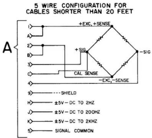
text_image
5 WIRE CONFIGURATION FOR CABLES SHORTER THAN 20 FEET A 1> +EXC, +SENSE A> 2> +SIG B> 3> CAL SENSE C> 4> -EXC,-SENSE 9> ----SHIELD H> ±5V-DC TO 2HZ J> ±5V-DC TO 200HZ K> ±5V-DC TO 2KHZ 5> SIGNAL COMMON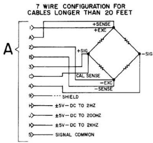
text_image
7 WIRE CONFIGURATION FOR CABLES LONGER THAN 20 FEET A I> A> 2> B> 3> C> 4> 9> H> J> K> 5> +SENSE +EXC +SIG CAL SENSE -EXC -SENSE -SIG SHIELD ±5V-DC TO 2HZ ±5V-DC TO 200HZ ±5V-DC TO 2KHZ SIGNAL COMMONNOTE: Shielding practice as shown above should be followed. Use 4 twisted pairs with individual shields.
Figure 4 (cont'd)
text_image
5 VOLT EXCITATION CONNECTION A D E REMOTE CALIBRATION CONNECTIONS A 8 5 A B 5 COM A 8 5 TTL COM
text_image
BALANCE Controls: The coarse (Rc) and fine (Rf) BALANCE controls are used to set the module output to zero when the transducer is unloaded. SPAN Controls: The coarse (c) and fine (f) SPAN controls are used to set the output to the Equivalent Input value when the CAL button is pressed. CAL Pushbutton: The CAL pushbutton provides for enabling or entering the calibration mode. The Cal resistor is shunted across the + Signal and + Sense terminals when the button is pressed, supplying an Equivalent Input value to the module.Figure 5. Front-Panel Description
ac power. Allow 5 minutes of warm-up for stabilization of transducer characteristics.
(b) With the transducer unloaded, set the module output to zero using the coarse ( R_c ) and fine ( R_f ) BALANCE controls. In some instances, an integral digital indicator will be used to display the conditioner output (Model 3270 or 3370). When only the conditioner is supplied (3170), an external indicator must be used to monitor the conditioner output.
(c) Load the transducer to a convenient up-scale value which is greater than one half of full scale. Adjust the coarse (c) and fine (f) SPAN controls until the output signal causes a reading equal to the dead weight value. Remove the dead weight, then press the CAL button and note the indicator reading obtained. This reading can now be used in future calibrations since it is related to a value obtained thru dead weight
Model 3170
calibration. To calibrate the instrument in the future, simply press the CAL button and adjust the SPAN controls to obtain the reading previously recorded after dead weight calibration.
(d) If dead weight calibration is not practical and the transducer manufacturer has supplied a calibration resistor (or resistor value), install the recommended calibration resistor. Now press the CAL button and adjust the SPAN controls until the module output is equal to the Equivalent Input value simulated by the installed calibration resistor.
If dead weight calibration is not practical and the transducer calibration data is unknown, the Equivalent Input value for the factory-installed calibration resistor can be approximated as follows, assuming that the mv/v sensitivity rating of the transducer and the bridge resistance is known.
$$ \mathrm{X} = \frac {2 5 0 0 0 \mathrm{R} _ {\mathrm{b}}}{\mathrm{KR} _ {\mathrm{c}}} $$
where X = Equivalent Input, % of full scale
R_b = bridge resistance, ohms
K = transducer sensitivity, mv/v full scale
R_c = calibration resistance, ohms (59 K installed)
Sample Calculation: Assume that K = 3.000 mv/v for a 5000-pound load cell (full scale) with a bridge resistance of 350 ohms.
$$ \mathrm{X} = \frac {25000 \times 350}{59000 \times 3} = 49.44 \% \text { of full scale} = 2472 \text { pounds } $$
4. BLOCK DIAGRAM DESCRIPTION
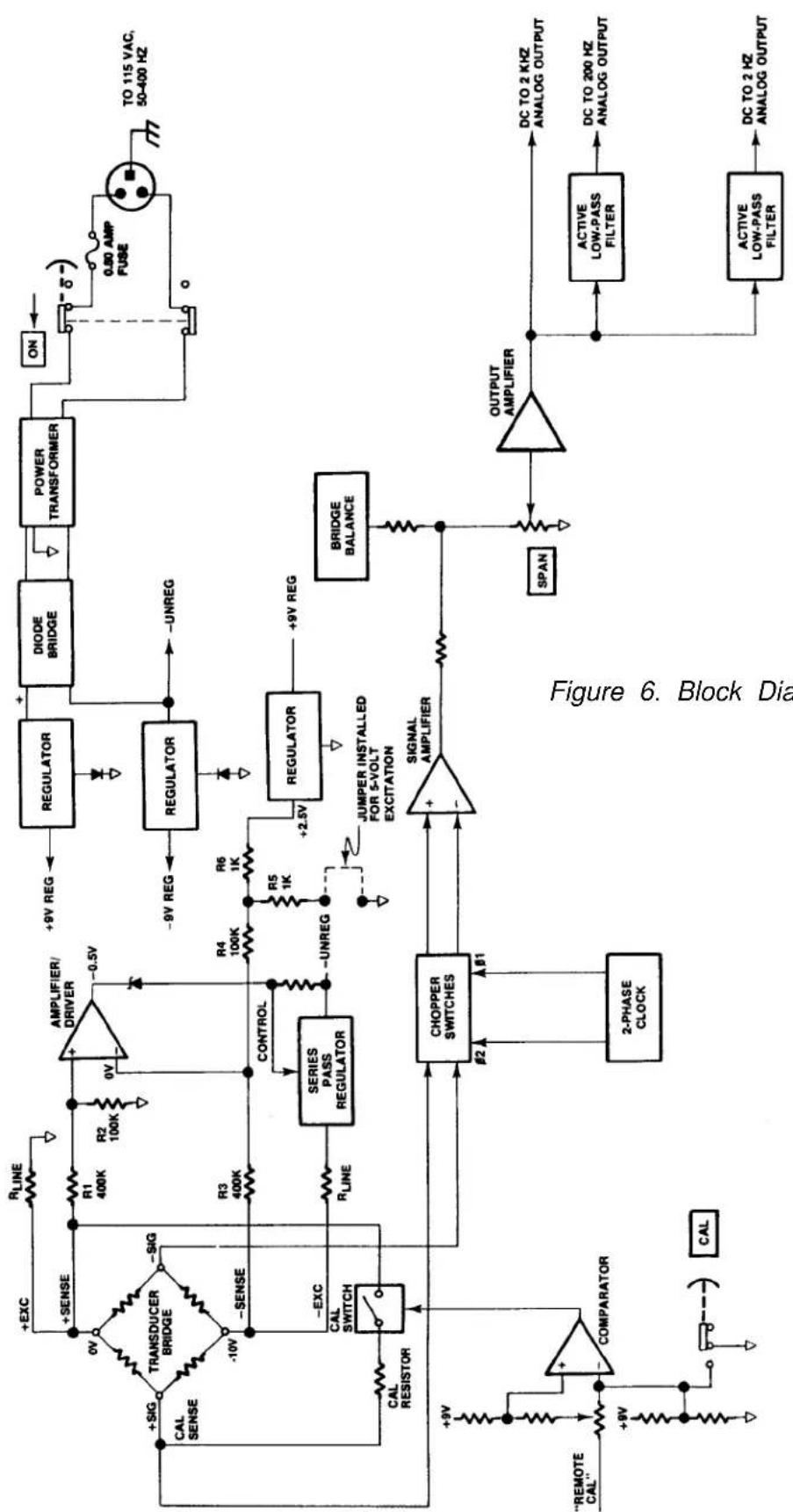
The purpose of this section is to explain how the 3170 works by using a simplified block diagram of the conditioner. This is not intended to be used as a detailed theory of operation discussion for personnel untrained in electronic technology, but as a simplified explanation of the detailed schematic diagram provided with this manual.
Refer to Figure 6. Primary power (115 volts ac, 50-400 Hz) is applied to the module by means of the attached power cable. A rear-panel slide switch is used to turn ON primary power. Overload protection is provided by a 0.25 ampere fuse
Daytronic Corporation
mounted on the conditioner printed-circuit board. When the slide switch is ON, primary power is applied to the power transformer which provides the necessary power-line isolation and the low ac voltages required to develop the regulated dc voltages used in the module. The secondary of the power transformer has a grounded center tap, and a diode bridge functions as two full-wave rectifiers to produce ±9 volts regulated dc. Two three-terminal regulators are used to develop these regulated voltages. The reference terminal of each regulator is biased with one or two diodes to make certain that a minimum regulated voltage of 9 volts is achieved. The proper diode biasing is accomplished at factory check out.
A dc reference voltage of +2.5 volts dc is further developed from regulated +9 volts by the use of a third three-terminal regulator. This precision dc reference is used to bias an amplifier/driver which works in conjunction with a series-pass regulator to regulate the excitation voltage at the transducer bridge. The excitation voltage is normally 10 volts dc, but a jumper can be installed at the module I/O connector to select a 5-volt excitation voltage. The excitation voltage is developed from the minus unregulated side of the diode bridge to more equally balance the current drain on the power transformer secondary. The series-pass regulator has short-circuit protection in the event that the excitation voltage is accidentally shorted at the transducer or module I/O connector.
Figure 6 shows the connections between the transducer bridge and the module made via a 7-wire cable. Optimum accuracy is obtained with the 7-wire configuration since the excitation voltage is regulated at the transducer bridge and a Cal Sense line is returned to the module for accurately setting the Equivalent Input value when the Cal resistor is shunted across one leg of the transducer bridge. The Calibration mode is entered (Cal resistor is shunted across the + Signal and + Sense lines) when the front-panel CAL button is pressed or the Remote Cal input at the module I/O connector is brought to a zero-volt level through the action of an external switch, transistor driver, etc. Either of these actions fires a comparator which, in turn, closes an analog switch in series with the Cal resistor.
The + and - Signal inputs from the transducer bridge are applied to a differential signal amplifier. Each leg of the signal amplifier inputs has approximately 100-megohms input impedance so that no loading is seen by the bridge. The signal amplifier is chopper stabilized to prevent drift which might result from temperature or component aging. A two-phase clock signal synchronized with power line frequency is used as the chopper signal. The differential signal amplifier also provides excellent common-mode rejection.
The bridge balance circuit immediately follows the signal amplifier. The BALANCE and SPAN controls act upon the output of the signal amplifier, not the bridge, to achieve the proper impedance isolation.
Three analog outputs of the conditioned strain gage signal are available at the module I/O connector. The three outputs provide three different passbands of dc to 2 kHz, dc to 200 Hz, and dc to 2 Hz. Output selection is a trade off between eliminating unwanted signals caused by vibration or increasing the time-to-answer (slew rate) of the conditioner. The 200-Hz and 2-Hz cutoff frequencies are achieved with the use of active low-pass filters. The rolloff of each output is 60 dB within a decade of the cutoff frequency.
5. VERIFICATION OF NORMAL OPERATION
It is the purpose of this section to aid the user in determining, in the event of a malfunction to which the Model 3170 is suspected of contributing, whether the module is functioning normally or whether it is a source of the observed trouble. In the event the module requires repair, a complete parts list, schematic diagram, and component location drawing are included in this manual. The user may also contact the factory Service Department or the local Daytronic Representative for assistance.
If the module is suspected of faulty operation, observe the following steps.
(a) If the module is totally inoperational (front panel power indicator does not light), check the primary power fuse (Fl) located on the conditioner printed-circuit board (see Figure 8). If the fuse is blown, replace it with a 0.50 ampere fuse. Before reapplying power, visually inspect the power cord wiring and the printed-circuit board for any discrepancy which could have caused the overload.
(b) If the transducer has some preloading, the BALANCE controls may not allow successful zeroing of the module output. This condition can be remedied by connecting a resistor (50 K-200 K range, metal-film type) from the + Signal terminal of the transducer to the + or - Excitation terminals. The Excitation terminal to which the connection is made is determined by the direction of the loading or off-zero reading.
(c) The inability to balance correctly where the module output reads totally off scale and the BALANCE controls have no authority can very likely be the result of a damaged or defective transducer or cable. This possibil-
flowchart
graph TD
    A[""CAL" --> B[COMPARATOR"]
    B --> C["2-PHASE CLOCK"]
    C --> D["CHOPPER SWITCHES"]
    D --> E["COMPRESSER"]
    E --> F["CONTROL"]
    F --> G["SERIES PASS REGULATOR"]
    G --> H["AMPLIFIER/ DRIVER"]
    H --> I["DIODE BRIDGE"]
    I --> J["POWER TRANSFORMER"]
    J --> K["ON"]
    K --> L["0.80 AMP FUSE"]
    L --> M["TO 115 VAC, 50-400 Hz"]
    M --> N["OUTPUT AMPLIFIER"]
    N --> O["DC TO 2 KHZ ANALOG OUTPUT"]
    N --> P["ACTIVE LOW-PASS FILTER"]
    P --> Q["DC TO 200 Hz ANALOG OUTPUT"]
    P --> R["ACTIVE LOW-PASS FILTER"]
    R --> S["DC TO 2 Hz ANALOG OUTPUT"]
    T["REMOTE CAL"] --> U["COMPARATOR"]
    U --> V["CAL RESISTOR"]
    V --> W["TRANSDUCER BRIDGE"]
    W --> X["+SIG CAL SENSE"]
    X --> Y["+EXC +SENSE"]
    Y --> Z["RLINE +0V 400K R1 100K R2 100K 0V"]
    Z --> AA["+9V REG -0.5V"]
    AA --> AB["RELIGANCE REGULATOR"]
    AB --> AC["DIODE BRIDGE"]
    AC --> AD["POWER TRANSFORMER"]
    AD --> AE["ON"]
    AE --> AF["0.80 AMP FUSE"]
    AF --> AG["TO 115 VAC, 50-400 Hz"]
Figure 6. Block Diagram
ity can be confirmed (or eliminated) by substituting a transducer and cable known to be in good condition or by simulating a balanced transducer, using either a commercially available transducer simulator or the simple star bridge arrangement shown in Figure 7. The star bridge simulates a conventional four-arm bridge in an exact condition of balance. To construct a star bridge connect four 10% carbon resistors as shown in Figure 7. Use 180-ohm resistors to simulate a 350-ohm bridge and use 56-ohm resistors to simulate a 120-ohm bridge. Neither the resistor values nor temperature characteristics are critical since the balance condition of a star bridge is not determined by the resistance values. Solder two resistors together, then solder the remaining two resistors together. Next, connect the two junctions together using a separate wire as shown. There is a good reason for this method of construction, and it should be followed. Connect the substitute or simulated transducer to the module I/O connector using a short 4-wire cable configuration as shown in Figure 4. Attempt to balance the substitute or simulated transducer. If conditions now appear to be normal, the transducer or cable is at fault. If the previous difficulties persist, the module is faulty.
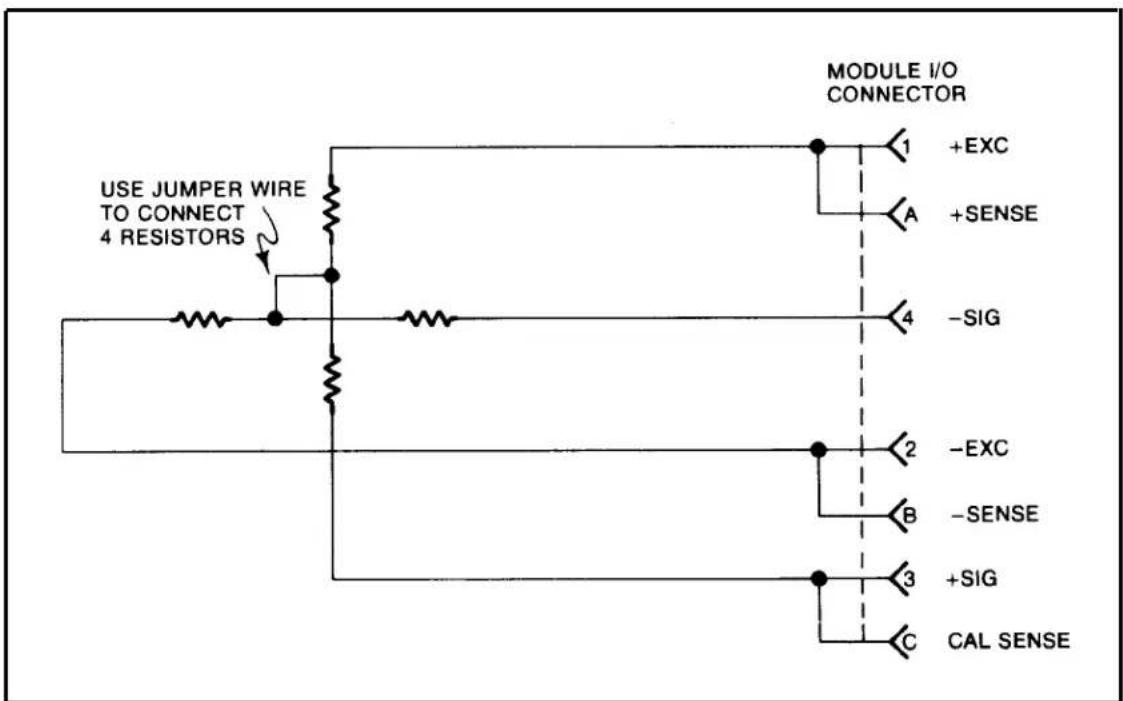
text_image
USE JUMPER WIRE TO CONNECT 4 RESISTORS MODULE I/O CONNECTOR 1 +EXC A +SENSE - SIG 2 -EXC B -SENSE 3 +SIG C CAL SENSEFigure 7. Star-Bridge Construction
3000 SERIES
"C" Option
4-20 mA CURRENT OUTPUT
INSTRUCTION MANUAL
1. General Description
Operating in this mode, any 3000 Series instrument can transmit high-accuracy measurement data as process signals for supervisory monitoring and control. ^1 Each “C” unit produces two kinds of analog output simultaneously: (1) its normal voltage output and (2) a current output continuously proportional to the voltage signal to within ±0.05% .
As normally shipped, this option generates a current output within the ISA standard signal range of 4 to 20 mA, corresponding to a range of 0 to +5 V. Bipolar ranges of ±16 mA and 4 to 12 to 20 mA are also available, each corresponding to -5 to +5 V. Voltage compliance is +5 V relative to Signal Common.
Pinout for I/O Connectors (REAR VIEW)

Fig. 1
Rear-Panel
Location of
3000C Current
Output Board

text_image
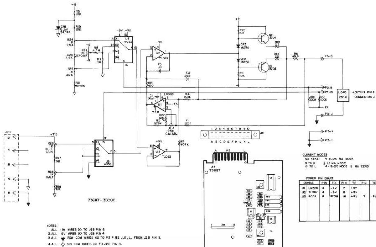
3000 "C Option" Board I/O Connector (20-pin)² Pin 1 Pin 10 Pin A Pin L Conditioner Board I/O Connector (20-pin)2. Connections / Output Mode Selection
Pin assignments for the 3000C board's 20-pin I/O connector (shown in Fig. 1) are given in the following table. ^3
Pin Number Function
8 CURRENT OUTPUT SIGNAL
Range will be standard unipolar 4-20 mA if Pins 9 and 10 are both unconnected; the output is single-ended, and should be returned to Pin J (COMMON)
9 ±16 mA MODE
Connecting Pin 9 to Pin K will set the current output range to bipolar ±16 mA
10 4-12-20 mA MODE
Connecting Pin 10 to Pin L will set the current output range to bipolar 4-12-20 mA (with 12 mA as effective "zero")
J COMMON
K, L for OUTPUT MODE SELECTION
1 NOTE: The "C" Option may NOT be used in combination with the "P," "G," "R," or "S" Option.
2 In Form 3 ("33XX") instruments with the "C" Option, current-output circuitry is integrated with the 3300 HI-LO Limits Board.
3 For all other (limit-related) I/O connections for Form 3 ("33XX") instruments with the "C" Option, see the Model 3300 HI-LO Limits Instruction Manual.
text_image
R6 10K R19 15K R24 12 MA R20 12.4 K R25 1K 4MA R21 9040K +9 +9V +9V U3 4052 I3 I4 X1 X2 X3 X4 A -9V +9V -9V +9V -9V +9V -9V +9V -9V +9V -9V +9V -9V +9V -9V +9V -9V +9V -9V +9V -9V +9V -9V +9V -9V +9V -9N 15X2 11X3 11X4 11X5 11X6 11X7 11X8 11X9 11X10 11X11 11X12 11X13 11X14 11X15 11X16 11X17 11X18 11X19 11X20 11X21 11X22 11X23 11X24 11X25 11X26 11X27 11X28 11X29 11X30 11X31 11X32 11X33 11X34 11X35 11X36 11X37 11X38 11X39 11X40 11X41 11X42 11X43 11X44 11X45 11X46 11X47 11X48 11X49 11X50 11X51 11X52 11X53 11X54 11X55 11X56 11X57 11X58 11X59 11X60 11X61 11X62 11X63 11X64 11X65 11X66 11X67 11X68 11X69 11X70 L308 3 3 3 3 3 3 3 3 3 3 3 3 3 3 3 3 3 3 3 3 3 3 3 3 3 3 3 3 3 3 3 3 3 3 3 3 3 3 3 3 3 3 3 3 3 3 3 3 3 3 0 P3-S B P3-ID P3-L D LOAD + OUTPUT PIN B COMMON PIN J + CURRENT MODES NO STAP 4 TO 20 MA MODE 9 TO K ± 16 MA MODE 4-Ⅱ-20 MODE I2 MA ZERO A B C D E F H U K L A4 T73687 POWER PIN CHART DEVICE PIN TO PIN TO PIN TO UI LM3CE 4 -9V 7 +9V U2 TLO62 4 -9V B PCOM 8 +9V I6 +9V 7 -9V U5 4052 B| CSP | C | 7-1-96 | WAS VERSION 003 | 50 | |
| TT | B | 2-7-96 | REV. 884 NO 81 | MAY | |
| A | G-24-96 | DATE: 10/07/2010 | M | ||
| ZONE | REV | DATED | DESCRIPTION | APR | CONTROL |
| CHL DCT | CSP | DAYTRONIC CORPORATION MIANSBURG, OHIO | |||
| CLM DTT | DFT | ||||
| DATE | 7-12-93 | REV. 7-1-96 | REV. LEVEL | C | |
| 4 TO 20 MA CURRENT OUTPUT CARD | s3000C NUMBER | ||||
3000 SERIES
"G" Option
DUAL GALVANIC ISOLATED OUTPUT
INSTRUCTION MANUAL
1. General Description
With this optional circuit board, a Form 1 (“31XX”) or Form 2 (“32XX”) instrument can furnish two independent galvanic outputs, fully isolated not only from each other but also from the 3000 instrument’s “common.” Each output is normally set at the factory for a full-scale range of 0-10 V-DC (±0.2%) when the data signal from the 3000 unit’s conditioner card is at its standard 5-V level. Though normally preset at “2.00,” each input’s gain can be adjusted within ±5%, if desired, by means of potentiometer controls on the G-option card.
The use of galvanically isolated outputs prevents ground-loop effects in interconnections with remote data-acquisition systems or controllers. The presence of two independent outputs lets you send collected data to two different systems or devices, each with its own ground.
Load limit for each output exceeds 10 kilohms. Output bandwidth is normally 40 Hz; the "G" option can be easily modified, however, for other bandwidths up to 500 Hz (contact the factory for details).
NOTE: The only other options that may be combined with the "G" option are the "B" (battery-powered) and "F" (230 V-AC-powered) options.
2. Additional 3000(G) Specifications
Output Range: ±10 V-DC full scale (2 mA max), normal; internal controls give approximately ±5% of adjustment authority on both SPAN and ZERO
Common-Mode Range: ±500 V, max
Common-Mode Rejection Ratio: DC: -120 dB; at 60 Hz: -60 dB
Linearity: ±0.1% of full scale
Maximum Zero Drift, After Warmup of One-Half Hour: ±0.2% of full scale*
Maximum Span Drift, After Warmup of One-Half Hour: ±0.2% of full scale*
* Applies to the 3000 "G" Option only and does not include possible drift contributed by the signal conditioner board of the base 3000 instrument.
3. Installation and Cabling
When viewing the 3000 instrument from the rear, the Galvanic Output Board is in the upper left of the rear panel (see Fig. 1). Access to the output signals is through a 20-pin edge card connector with a key slot between contact pads 4 and 5. The user must provide his own cable connection to the card, pinout for which is as follows:
Pin No. (see Fig. 1) Function
2,B SIGNAL 1 OUT
1,A,3,C ISO COM 1
9,K SIGNAL 2 OUT
8,J,10,L ISO COM 2
Cabling of the isolated analog outputs is shown in Fig. 2. Each output is single-ended and returns to its own ISO-LATED COMMON. Each output's SHIELD should be tied to the instrument chassis via one of the screws holding the rear panel.
4. Calibration
NO ADJUSTMENT OF THE G OPTION IS NECESSARY DURING NORMAL USE.** Follow the normal calibration procedure given in the respective 3000 Instrument Instruction Manual.
** As mentioned above, separate ZERO and SPAN adjustment controls are provided on the G Option board for each isolated output, if it is desired to refine the "2.00" gain to which the output has been set prior to shipment. These controls, shown in Fig. 3, may be accessed by removing the 3000 instrument's front panel.
Fig. 1
Rear-Panel
Location of
3000G Galvanic
Output Board
Pinout for I/O Connectors (REAR VIEW)

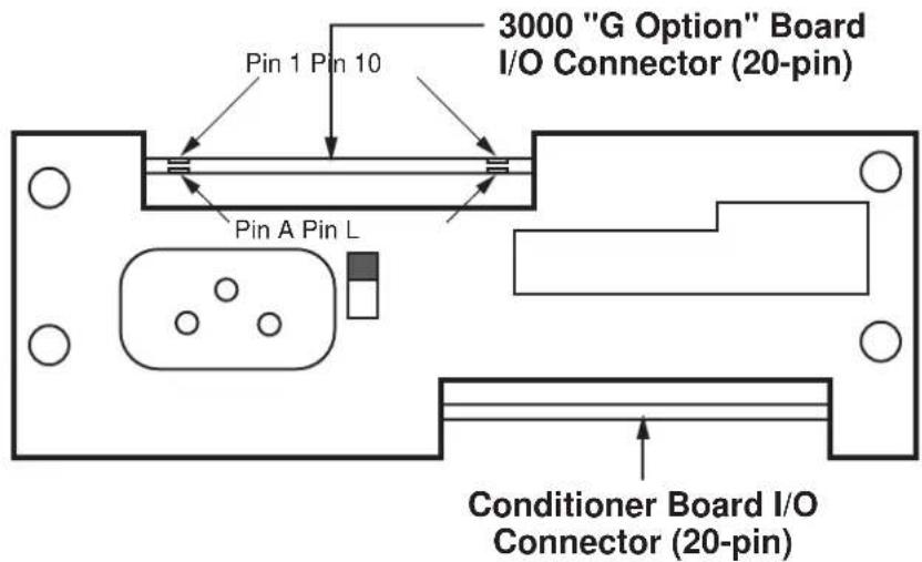
text_image
3000 "G Option" Board I/O Connector (20-pin) Pin 1 Pin 10 Pin A Pin L Conditioner Board I/O Connector (20-pin)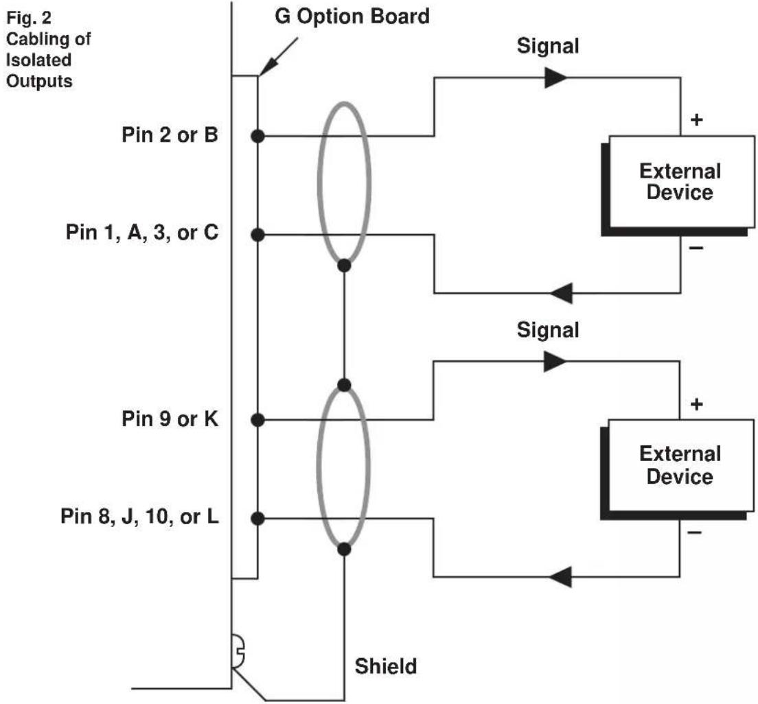
flowchart
graph TD
    A["Pin 2 or B"] --> B["G Option Board"]
    C["Pin 1, A, 3, or C"] --> B
    D["Pin 9 or K"] --> B
    E["Pin 8, J, 10, or L"] --> B
    B --> F["External Device"]
    F --> G["Shield"]
    G --> H["External Device"]
    H --> I["+"]
    I --> J["Signal"]
    J --> K["+"]
    K --> L["External Device"]
    L --> M["-"]
    M --> N["+"]
    N --> O["External Device"]
    O --> P["-"]
    P --> Q["+"]
    Q --> R["Shield"]
Fig. 3 Location of Internal G-Option Controls

text_image
FRONT VIEW 3100G CARD CONTROLS LOCATED BEHIND FRONT PANEL. Conditioner CARD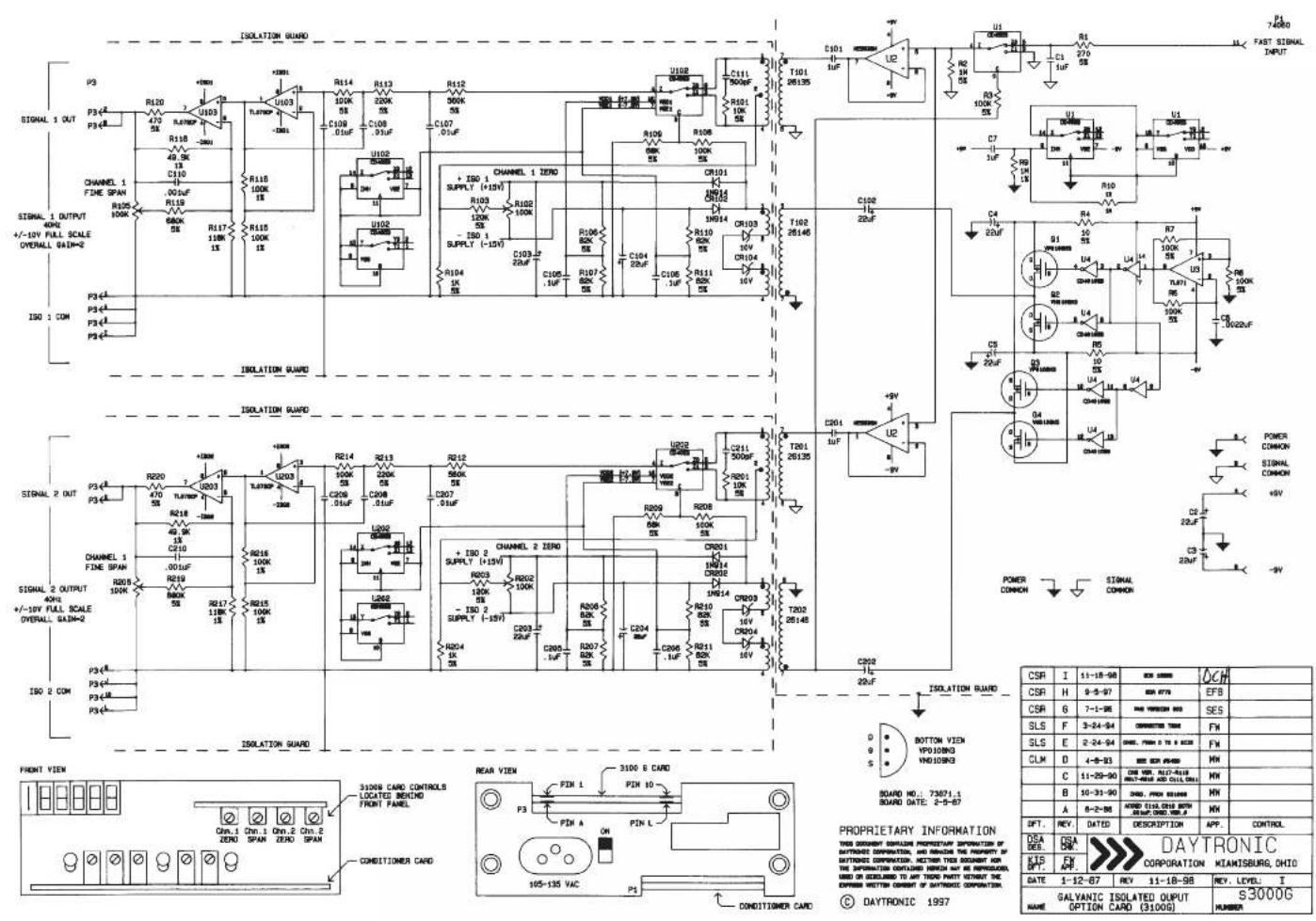
text_image
ISOLATION GUARD P3 P34 P35 R120 U103 R118 49.0K C110 .00uF R119 680K R117 180K R115 100K R113 100K R112 900K C107 .01uF U102 + ISO 1 SUPPLY (+15V) R103 120K - ISO 1 SUPPLY (-15V) R104 1K C105.1uF C106.2uF C107.3uF C108.4uF C109.5uF C110.6uF C111.7uF C112.8uF C113.9uF C114.0uF C115.1uF C116.2uF C117.3uF C118.4uF C119.5uF C120.6uF C121.7uF C122.8uF C123.9uF C124.0uF C125.1uF C126.2uF C127.3uF C128.4uF C129.5uF C130.6uF C131.7uF C132.8uF C133.9uF C134.0uF C135.1uF C136.2uF C137.3uF C138.4uF C139.5uF C140.6uF C141.7uF C142.8uF C143.9uF C144.0uF C145.1uF C146.2uF C147.3uF C148.4uF C149.5uF C150.6uF C151.7uF C152.8uF C153.9uF C154.0uF C155.1uF C156.2uF C157.3uF C158.4uF C159.5uF C160.6uF C161.7uF C162.8uF C163.9uF C164.0uF C165.1uF C166.2uF C167.3uF C168.4uF C169.5uF C170.6uF C171.7uF C172.8uF C173.9uF C174.0uF C175.1uF C176.2uF C177.3uF C178.4uF C179.5uF C180.6uF C181.7uF C182.8uF C183.9uF C184.0uF C185.1uF C186.2uF C187.3uF C188.4uF C189.5uF C190.6uF C191.7uF C192.8uF C193.9uF C200.0kΩ/Ω/Ω/Ω/Ω/Ω/Ω/Ω/Ω/Ω/Ω/Ω/Ω/Ω/Ω/Ω/Ω/Ω/Ω/Ω/Ω/Ω/Ω/Ω/Ω/Ω/Ω/Ω/Ω/Ω/Ω/Ω/Ω/Ω/Ω/Ω/Ω/Ω/Ω/Ω/Ω/Ω/Ω/Ω/Ω/Ω/Ω/Ω/Ω/Ω/Ω/ ISOLATION GUARD P34A P34B P34B(A) P34B(B) P34B(C) P34B(D) P34B(E) P34B(F) P34B(G) P34B(H) P34B(I) P34B(J) P34B(K) P34B(L) P34B(M) P34B(N) P34B(O) P34B(P) P34B(Q) P34B(R) P34B(S) P34B(T) P34B(U) P34B(V) P34B(X) P34B(Y) P34B(Z) P34B(C) P34B(D) P34B(E) P34B(F) P34B(G) P34B(H) P34B(I) P34B(J) P34B(K) P34B(L) P34B(M) P34B(N) P34B(O) P34B(P) P34B(Q) P34B(R) P35A(0)A(0)A(0)A(0)A(0)A(0)A(0)A(0)A(0)A(0)A(0)A(0)A(0)A(0)A(0)A(0)A(0)A(0)A(0)A(0)A(0)A(0)A(0)A(0)A(0)A(0) ISOLATION GUARD P34A(0)A(0)A(0)A(0)A(0)A(0)A(0)A(0)A(0)A(0)A(0)A(0)A(0)A(0)A(0)A(0)A(0)A(0)A(0)A(0) ISOLATION GUARD (CHANNEL 2 ZERO) + ISO 2 SUPPLY (+15V) + ISO 2 SUPPLY (-15V) + ISO 2 SUPPLY (-25V) + ISO 2 SUPPLY (-35V) + ISO 2 SUPPLY (-45V) + ISO 2 SUPPLY (-55V) + ISO 2 SUPPLY (-65V) + ISO 2 SUPPLY (-75V) + ISO 2 SUPPLY (-85V) + ISO 2 SUPPLY (-95V) + ISO 2 SUPPLY (-105V) + ISO 2 SUPPLY (-115V) + ISO 2 SUPPLY (-125V) + ISO 2 SUPPLY (-135V) + ISO 2 SUPPLY (-145V) + ISO 2 SUPPLY (-155V) + ISO 2 SUPPLY (-165V) + ISO 2 SUPPLY (-175V) + ISO 2 SUPPLY (-185V) + ISO 2 SUPPLY (-195V) + ISO 2 SUPPLY (-205V) + ISO 2 SUPPLY (-215V) + ISO 2 SUPPLY (-225V) + ISO 2 SUPPLY (-235V) + ISO 2 SUPPLY (-245V) + ISO 2 SUPPLY (-255V) + ISO 2 SUPPLY (-265V) + ISO 2 SUPPLY (-275V) + ISO 2 SUPPLY (-285V) + ISO 2 SUPPLY (-295V) + ISO 2 SUPPLY (-305V) + ISO 2 SUPPLY (-315V) + ISO 2 SUPPLY (-325V) + ISO 2 SUPPLY (-335V) + ISO 2 SUPPLY (-345V) + ISO 2 SUPPLY (-355V) + ISO 2 SUPPLY (-365V) + ISO 2 SUPPLY (-375V) + ISO 2 SUPPLY (-385V) + ISO 2 SUPPLY (-395V) + ISO 2 SUPPLY (-405V) + ISO 2 SUPPLY (-415V) + ISO 2 SUPPLY (-425V) + ISO 2 SUPPLY (-435V) + ISO 2 SUPPLY (-445V) + ISO 2 SUPPLY (-455V) + ISO 2 SUPPLY (-465V) + ISO 2 SUPPLY (-475V) + ISO 2 SUPPLY (-485V) + ISO 2 SUPPLY (-495V) + ISO 2 SUPPLY (-505V) + ISO 2 SUPPLY (-515V) + ISO 2 SUPPLY (-525V) + ISO 2 SUPPLY (-535V) + ISO 2 SUPPLY (-545V) + ISO 2 SUPPLY (-555V) + ISO 2 SUPPLY (-565V) + ISO 2 SUPPLY (-575V) + ISO 2 SUPPLY (-585V) + ISO 2 SUPPLY (-595V) + ISO 2 SUPPLY (-605V) + ISO 2 SUPPLY (-615V) + ISO 2 SUPPLY (-625V) + ISO 2 SUPPLY (-635V) + ISO 2 SUPPLY(-645V)- + ISO 2 SUPPLY(-655V)- + ISO 2 SUPPLY(-665V)- + ISO 2 SUPPLY(-675V)- + ISO 2 SUPPLY(-685V)- + ISO 2 SUPPLY(-695V)- + ISO 2 SUPPLY(-705V)- + ISO 2 SUPPLY(-715V)- + ISO 2 SUPPLY(-725V)- + ISO 2 SUPPLY(-735V)- + ISO 2 SUPPLY(-745V)- + ISO 2 SUPPLY(-755V)- + ISO 2 SUPPLY(-765V)- + ISO 2 SUPPLY(-775V)- + ISO 2 SUPPLY(-785V)- + ISO 2 SUPPLY(-795V)- + ISO 2 SUPPLY(-805V)- + ISO 2 SUPPLY(-815V)- + ISO 2 SUPPLY(-825V)- + ISO 2 SUPPLY(-835V)- + ISO 2 SUPPLY(-845V)- + ISO 2 SUPPLY(-855V)- + ISO 2 SUPPLY(-865V)- + ISO 2 SupPLY(-875V)- + ISO 2 SupPLY(-885V)- + ISO 2 SupPLY(-895V)- + ISO 2 SupPLY(-905V)- + ISO 2 SupPLY(-915V)- + ISO 2 SupPLY(-925V)- + ISO 2 SupPLY(-935V)- + ISO 2 SupPLY(-945V)- + ISO 2 SupPLY(-955V)- + ISO 2 SupPLY(-965V)- + ISO 2 SupPLY(-975V)- + ISO 2 SupPLY(-985V)- + ISO 2 SupPLY(-995V)- + ISO 2 SupPLY(-999M)(DINION VOUT RONDS DIP SING OF ADMI SING OF ADMI SING OF ADMI SING OF ADMI SING OF ADMI SING OF ADMI SING OF ADMI SING OF ADMI SING OF ADMI SING OF ADMI SING OF ADMI SING OF ADMI SING OF ADMI SING OF ADMI SING OF ADMI SING OF ADMI SING OF ADMI SING OF ADMI SING OF ADMI SING OF ADMI SING OF A| CSR | I | 11-18-98 | BEX 20000 | OCH |
| CSR | H | 9-5-97 | BEX 9770 | EF8 |
| CSR | 6 | 7-1-96 | NEW WISHER 800 | SES |
| SLS | F | 3-24-94 | CORRECTED 7000 | FN |
| SLS | E | 2-24-94 | DWG. FING 5 700 & 8200 | FN |
| CLM | D | 4-9-93 | BEX 800-4940 | MN |
| C | 11-29-90 | DBW VIB. ALICE-4018 NEW WISE AND CHINA | MN | |
| B | 10-31-90 | DWG. PION 55000 | MN | |
| A | 8-2-98 | AWGD 515-035 WITH GROUP HOLD-A | MN | |
| DFT. | REV. | DATED | DESCRIPTION | APP. CONTROL |
| DSA DES. | DSA DES. | DAYTRONIC CORPORATION | MIKANSBURG, OHIO | |
| KTS DFT. | FX DFT. | |||
| DATE | 1-12-67 | REV 11-18-98 | REV. LEVEL. I | |
| GALVANIC ISOLATED OUTPUT NAME OPTION CARD (3100G) | s3000G NUMBER | |||

DAYTRONIC
Daytronic Corporation