3140ABC - Measurement Daytronic - Free user manual and instructions
Find the device manual for free 3140ABC Daytronic in PDF.

User questions about 3140ABC Daytronic
0 question about this device. Answer the ones you know or ask your own.
Ask a new question about this device
Download the instructions for your Measurement in PDF format for free! Find your manual 3140ABC - Daytronic and take your electronic device back in hand. On this page are published all the documents necessary for the use of your device. 3140ABC by Daytronic.
USER MANUAL 3140ABC Daytronic
Copyright © 1996, Daytronic Corporation. All rights reserved.
No part of this document may be reprinted, reproduced, or used in any form or by any electronic, mechanical, or other means, including photocopying and recording, or in any information storage and retrieval system, without permission in writing from Daytronic Corporation. All specifications are subject to change without notice.
MODEL
3140A
FREQUENCY CONDITIONER
INSTRUCTION MANUAL
Model 3140A Frequency Conditioner Instruction Manual
The Model 3140A Frequency Conditioner accepts any type of AC or pulse input signal, irrespective of waveform. It produces a standard five-volt analog output, with low-pass corner frequency of 2 or 10 Hz, depending on the input frequency range selected. This output is precisely proportional to the frequency of the source.
I. Specifications: Table 1
Input Type: Any AC signal, single-ended or differential, irrespective of waveform.
Input Sensitivity: Continuously adjustable from 0.1 to 200 V via front-panel control. Input Sensitivity decreases above 10 KHz by 0.01 V/kHz to 0.5 V at 50 kHz.
Input Threshold Level: Automatic triggering of squarer at 75 and 25 percent of the input amplitude.
Input Frequency Ranges: Full-scale frequency ranges are selected with internal switches. Range switches of 100, 1000, and 10000 and Multiplier switches of x1, x2, and x5 provide nine frequency ranges (see Table 2).
Analog Output: 0 to ±5 V, with 50% overrange, 5 mA max. Active low-pass filtering provides for rolloff of 60 dB per decade above corner frequency. Corner frequency is 2 Hz for input ranges of 100, 200, and 500 Hz; it is 10 Hz for all other ranges (1000 to 50000 Hz).
Output Ripple and Noise: Less than 0.1% of full scale from 20 to 100% of the selected range.
Step-Function Response: Response time (to 99.9% of final value) is 1.8 seconds for 100-, 200-, and 500-Hz ranges, and 350 milliseconds for all other ranges.
Accuracy: 0.05% of full scale.
Dimensions: 1.7 x 4.41 x 8.5 (HWD inches).
Operating Temperature Range: 0 to +130 degrees F.
Power Requirements: 105 to 135 W-AC, 50 to 400 Hz at 5 W max.
The Model 3140A is also available in two other forms. The Model 3240A contains a Digital Indicator to display the analog output. The Model 3340A is identical to the 3240A, except that it also includes high-low limit monitoring. See separate Model 3200/3300 and Model 3300 Instruction Manuals.
II. Installation and Cabling
- MOUNTING: 3000 Series instruments can be operated as bench-top, rack-mounted, or panel-mounted units. See Fig. 1. Up to four 3000 Series instruments can be mounted in a standard 19-inch rack, using the 1-3/4" high Model 3004 Adaptor. The following reassembly procedure lets you quickly mount any 3000 Series unit in your own precut panel (see cutout dimensions in Fig. 1C).
IMPORTANT: The unit is shipped with two spacer washers on the securing screws of the rear-panel I/O Connector. When panel-mounting the unit, you MUST REMOVE THESE WASHERS, so that the printed-circuit board may move forward about 1/8" during Step f, below.
a. Remove the front panel (one small flat-head screw near each edge--see Fig. 2).
Fig. 1 Instrument Mounting Dimensions
| A. Bench Mounting | |
| B. Rack Mounting | |
| C. Panel Mounting |
b. Remove the front bezel (four fillister-head screws fasten it to the metal housing--see Fig. 2).
c. Make the panel cutout and drill the screw clearance holes shown in Figs. 1C and 2. The front bezel can be used as a template to define the rectangular cutout and to locate the clearance holes.
d. Hold the instrument behind the panel and use the four mounting screws to reattach the front bezel to the metal housing, from the front of the panel.
e. Reinstall the front panel.
f. Tighten--BUT DON'T OVERTIGHTEN--the two securing screws of the rear-panel I/O Connector. This will push forward the printed-circuit board and all front-panel buttons and controls by about 1/8"--which is consequently the maximum panel thickness allowed.

text_image
3000 SERIES MODULE PANEL WITH CUT OUT AND MOUNTING HOLES 6-32 x ½ FILLISTER- HEAD SCREW FRONT BEZEL 2-56 x ¾ FLAT- HEAD SCREW FRONT PANEL Fig. 2 Instrument Panel Mounting-
AC POWER CONNECTION: Connect the supplied power cable to a 105-135 V-AC, 50-400 Hz source (for "F" versions, 210-260 V-AC; for "B" versions, there is no external power connection). This is a three-conductor cord, plugging into the AC power connector at the rear of the unit; the offset pin connects to earth ground. To maintain the safety ground when operating from a two-contact outlet, use a 3-prong-to-2-prong adapter and connect the green pigtail on the adapter to earth ground.
-
TRANSDUCER CABLING: The transducer is connected via the 3140A's rear-panel I/O Connector. For pinout, see Fig. 3A, below. The frequency input can be single-ended or differential, as shown in Fig. 3C and 3B, respectively. Shielded, twisted-pair cable is recommended. Fig. 3D gives the required cabling when the 3140A is used with Lebow Zero Velocity Sensors.
Fig. 3 I/O Wiring Data
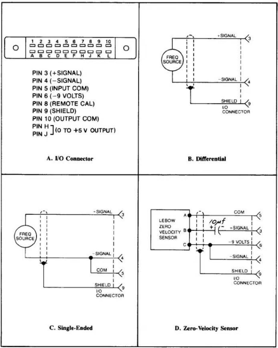
text_image
1 2 3 4 5 6 7 8 9 10 A B C D E F H J K L PIN 3 (+SIGNAL) PIN 4 (-SIGNAL) PIN 5 (INPUT COM) PIN 6 (-9 VOLTS) PIN 8 (REMOTE CAL) PIN 9 (SHIELD) PIN 10 (OUTPUT COM) PIN H ](0 TO +5 V OUTPUT) PIN J A. I/O Connector B. Differential C. Single-Ended D. Zero-Velocity Sensor- RANGE SELECTION: To access the internal bank of ten numbered range-selection switches, remove the 3140A's front panel (two screws near each edge--see Fig. 2). To select the desired full-scale frequency range, place in the ON (i.e., downward) position the switches indicated in Table 2, below.
Table 2. Frequency Range Selection
| Range Switches: | Multiplier Switches: | ||
| Range | Switch(es) | Factor | Switch(es) |
| 0 to 100 Hz | # 1,2,3,4 | x1 | # 10 |
| 0 to 1000 Hz | # 5 | x2 | # 8,9 |
| 0 to 10000 Hz | # 6 | x5 | # 7 |
| TO SET A FULL-SCALE RANGE OF: | PLACE THESE SWITCHES ON*: | ||
| 100 Hz | # 1,2,3,4,10 | ||
| 200 Hz | # 1,2,3,4,8,9 | ||
| 500 Hz | # 1,2,3,4,7 | ||
| 1000 Hz | # 5,10 | ||
| 2000 Hz | # 5,8,9 | ||
| 5000 Hz | # 5,7 | ||
| 10000 Hz | # 6,10 | ||
| 20000 Hz | # 6,8,9 | ||
| 50000 Hz | # 6,7 | ||
* ON = switch closed (downward position)
- REMOTE CALIBRATION CHECK: The 3140A can be placed in the REMOTE CAL mode by connecting Pin 5 of the I/O Connector (Signal Common) to Pin 8. This provides a means of periodically monitoring the instrument from a remote location without pressing the front-panel CAL button. When the Remote Cal input (Pin 8) is brought to a 0-volt (ground) level through the action of an external switch, transistor driver, etc. (see Fig. 4), the effect is the same as when the CAL button is pushed (see Section III, below).

text_image
COM TTL COM I/O CONNECTORFig. 4 Remote Calibration Connections
III. Calibration
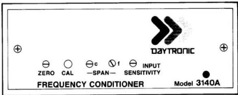
- Turn power ON by placing the rear-panel slide switch in the upward position. With application of AC power, the front-panel red LED indicator should light.
- ZERO ADJUSTMENT: Establish a zero input to the 3140A by bringing the transducer frequency to zero or by disconnecting the transducer from the 3140A I/O Connector. Then adjust the front-panel ZERO control (see Fig. 5, above) to produce an output of zero.
- SPAN ADJUSTMENT: Press the front-panel CAL button. The input signal is now replaced by a digitally divided, crystal-controlled frequency equal to 80% of the full-scale value of the input range selected in Step 4, Section II, above. Now adjust the Coarse and Fine SPAN controls to produce an output equal to 80% of the selected range. The 3140A is normally scaled for a full-scale output of +5 volts.
- TRIGGER LEVEL ADJUSTMENT: Turn the front-panel INPUT SENSITIVITY control fully counterclockwise. Then, using the transducer as a frequency source, apply the lowest-valued input signal for which a valid reading is required. Then turn the INPUT SENSITIVITY control clockwise until a stable output is observed.
FOR MODELS 3240A AND 3340A ONLY:
1A. POWER-UP and ZERO ADJUSTMENT: as in Steps 1 and 2, above.
2A. SCALE SELECTION: Determine the full-scale output of the transducer in terms of the desired unit of measurement. For example, the full-scale output for a flowmeter might be 5000 Hz, which corresponds (in units of flow) to a measurement of, say, 728.2 cfm. Then select the full-scale frequency range, as explained in Step 4 of Section II. In our example, this would be the 5000-Hz setting.
Now select the Digital Indicator scale that accommodates the full-scale output of the transducer in the desired unit of measurement. In our example, this scale would be ± 10000, with decimal point to the left of the last zero, giving a full-scale reading of 1000.0, to accommodate a full-scale measurement of 728.2 cfm. For the setting of scale and decimal-point location, refer to the Model 3200/3300 Instruction Manual.
text_image
DAYTRONIC ZERO CAL SPAN SENSITIVITY FREQUENCY CONDITIONER Model 3140AFig. 5 Model 3140A Front Panel
3A. SPAN ADJUSTMENT: Apply an input signal with a frequency equal to the rated full-scale output of the transducer. Then adjust the Coarse and Fine SPAN controls to produce a readout on the indicator of the value determined in Step 2A, above--that is, of the full-scale transducer output in terms of the desired unit of measurement (e.g., 728.2 cfm).
4A. TRIGGER LEVEL ADJUSTMENT: as in Step 4, above.
IV. Verification of Normal Operation
If the Model 3140A is suspected of faulty operation, you should do the following:
- If the unit is TOTALLY INOPERATIONAL (front-panel LED indicator does not light), first check the primary power fuse (F1) located on the standup board which forms the power-cord connection point. If this fuse is blown, replace it with a 0.50-amp fuse ("F" version, 0.125-amp but not before determining the cause of overload (inspect the input power connections for any short-circuiting, etc.).
- Push the front-panel CAL button, and observe the analog output. If it is stable, noise-free, and adjustable via the Coarse and Fine SPAN controls, then you can assume that all circuits--with the exception of the front-end amplifier and trigger circuits--are functioning normally.
- To check the front-end circuitry, replace the transducer and cable with a transducer and cable known to be in good condition and operating reliably. If the 3140A works properly with this different input source, then the problem most likely lies in the original transducer/cable. However, if the observed malfunction persists after this substitution, repairs to the 3140A are probably indicated.
3000 SERIES
"C" Option
4-20 mA CURRENT OUTPUT
INSTRUCTION MANUAL
1. General Description
Operating in this mode, any 3000 Series instrument can transmit high-accuracy measurement data as process signals for supervisory monitoring and control. ^1 Each “C” unit produces two kinds of analog output simultaneously: (1) its normal voltage output and (2) a current output continuously proportional to the voltage signal to within ±0.05% .
As normally shipped, this option generates a current output within the ISA standard signal range of 4 to 20 mA, corresponding to a range of 0 to +5 V. Bipolar ranges of ±16 mA and 4 to 12 to 20 mA are also available, each corresponding to -5 to +5 V. Voltage compliance is +5 V relative to Signal Common.
Pinout for I/O Connectors (REAR VIEW)

Fig. 1
Rear-Panel
Location of
3000C Current
Output Board
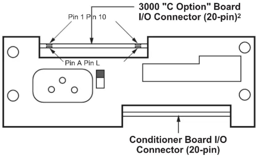
text_image
3000 "C Option" Board I/O Connector (20-pin)² Pin 1 Pin 10 Pin A Pin L Conditioner Board I/O Connector (20-pin)2. Connections / Output Mode Selection
Pin assignments for the 3000C board's 20-pin I/O connector (shown in Fig. 1) are given in the following table. ^3
Pin Number Function
8 CURRENT OUTPUT SIGNAL
Range will be standard unipolar 4-20 mA if Pins 9 and 10 are both unconnected; the output is single-ended, and should be returned to Pin J (COMMON)
9 ±16 mA MODE
Connecting Pin 9 to Pin K will set the current output range to bipolar ±16 mA
10 4-12-20 mA MODE
Connecting Pin 10 to Pin L will set the current output range to bipolar 4-12-20 mA (with 12 mA as effective "zero")
J COMMON
K, L for OUTPUT MODE SELECTION
^1 NOTE: The “C” Option may NOT be used in combination with the “P,” “G,” “R,” or “S” Option.
^2 In Form 3 (“33XX”) instruments with the “C” Option, current-output circuitry is integrated with the 3300 HI-LO Limits Board.
^3 For all other (limit-related) I/O connections for Form 3 (“33XX”) instruments with the “C” Option, see the Model 3300 HI-LO Limits Instruction Manual.
text_image
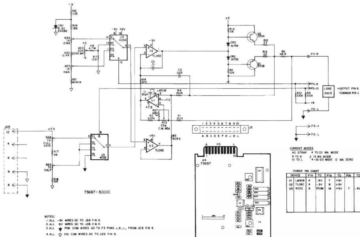
R6 10K R19 15K R24 12 MA R20 12.4 K R25 1K 4MA R21 9040K +9 +9V +9V U3 4052 I3 I4 X1 X2 X3 X4 A -9V +9V -9V +9V -9V +9V -9V +9V -9V +9V -9V +9V -9V +9V -9V +9V -9V +9V -9V +9V -9V +9V -9V +9V -9V +9V -9N 15X2 11X3 11X4 11X5 11X6 11X7 11X8 11X9 11X10 11X11 11X12 11X13 11X14 11X15 11X16 11X17 11X18 11X19 11X20 11X21 11X22 11X23 11X24 11X25 11X26 11X27 11X28 11X29 11X30 11X31 11X32 11X33 11X34 11X35 11X36 11X37 11X38 11X39 11X40 11X41 11X42 11X43 11X44 11X45 11X46 11X47 11X48 11X49 11X50 11X51 11X52 11X53 11X54 11X55 11X56 11X57 11X58 11X59 11X60 11X61 11X62 11X63 11X64 11X65 11X66 11X67 11X68 11X69 11X70 L308 3 3 3 3 3 3 3 3 3 3 3 3 3 3 3 3 3 3 3 3 3 3 3 3 3 3 3 3 3 3 3 3 3 3 3 3 3 3 3 3 3 3 3 3 3 3 3 3 3 3 0 P3-S B P3-ID P3-L D LOAD + OUTPUT PIN B COMMON PIN J + CURRENT MODES NO STAP 4 TO 20 MA MODE 9 TO K ± 16 MA MODE 4-Ⅱ-20 MODE I2 MA ZERO A B C D E F H U K L A4 T73687 POWER PIN CHART DEVICE PIN TO PIN TO PIN TO UI LM3CE 4 -9V 7 +9V U2 TLO62 4 -9V B PCOM 8 +9V I6 +9V 7 -9V U5 4052 B| CSP | C | 7-1-96 | WAS VERSION 003 | 50 | |
| TT | B | 2-7-96 | REV. 884 NO 81 | MAY | |
| A | G-24-96 | DATE: 10/07/2010 | M | ||
| ZONE | REV | DATED | DESCRIPTION | APR | CONTROL |
| CHL DCT | CSP | DAYTRONIC CORPORATION MIANSBURG, OHIO | |||
| CLM DT | DFT | ||||
| DATE | 7-12-93 | REV. 7-1-96 | REV. LEVEL | C | |
| 4 TO 20 MA CURRENT OUTPUT CARD | s3000C NUMBER | ||||
3000 SERIES
"G" Option
DUAL GALVANIC ISOLATED OUTPUT
INSTRUCTION MANUAL
1. General Description
With this optional circuit board, a Form 1 (“31XX”) or Form 2 (“32XX”) instrument can furnish two independent galvanic outputs, fully isolated not only from each other but also from the 3000 instrument’s “common.” Each output is normally set at the factory for a full-scale range of 0-10 V-DC (±0.2%) when the data signal from the 3000 unit’s conditioner card is at its standard 5-V level. Though normally preset at “2.00,” each input’s gain can be adjusted within ±5%, if desired, by means of potentiometer controls on the G-option card.
The use of galvanically isolated outputs prevents ground-loop effects in interconnections with remote data-acquisition systems or controllers. The presence of two independent outputs lets you send collected data to two different systems or devices, each with its own ground.
Load limit for each output exceeds 10 kilohms. Output bandwidth is normally 40 Hz; the "G" option can be easily modified, however, for other bandwidths up to 500 Hz (contact the factory for details).
NOTE: The only other options that may be combined with the "G" option are the "B" (battery-powered) and "F" (230 V-AC-powered) options.
2. Additional 3000(G) Specifications
Output Range: ±10 V-DC full scale (2 mA max), normal; internal controls give approximately ±5% of adjustment authority on both SPAN and ZERO
Common-Mode Range: ±500 V, max
Common-Mode Rejection Ratio: DC: -120 dB; at 60 Hz: -60 dB
Linearity: ±0.1% of full scale
Maximum Zero Drift, After Warmup of One-Half Hour: ±0.2% of full scale*
Maximum Span Drift, After Warmup of One-Half Hour: ±0.2% of full scale*
* Applies to the 3000 "G" Option only and does not include possible drift contributed by the signal conditioner board of the base 3000 instrument.
3. Installation and Cabling
When viewing the 3000 instrument from the rear, the Galvanic Output Board is in the upper left of the rear panel (see Fig. 1). Access to the output signals is through a 20-pin edge card connector with a key slot between contact pads 4 and 5. The user must provide his own cable connection to the card, pinout for which is as follows:
Pin No. (see Fig. 1) Function
2,B SIGNAL 1 OUT
1,A,3,C ISO COM 1
9,K SIGNAL 2 OUT
8,J,10,L ISO COM 2
Cabling of the isolated analog outputs is shown in Fig. 2. Each output is single-ended and returns to its own ISO-LATED COMMON. Each output's SHIELD should be tied to the instrument chassis via one of the screws holding the rear panel.
4. Calibration
NO ADJUSTMENT OF THE G OPTION IS NECESSARY DURING NORMAL USE.** Follow the normal calibration procedure given in the respective 3000 Instrument Instruction Manual.
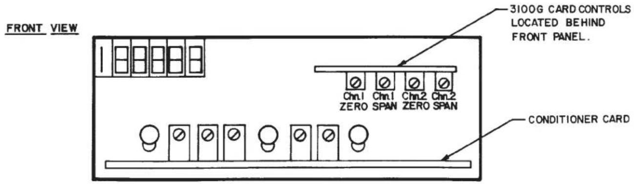
** As mentioned above, separate ZERO and SPAN adjustment controls are provided on the G Option board for each isolated output, if it is desired to refine the "2.00" gain to which the output has been set prior to shipment. These controls, shown in Fig. 3, may be accessed by removing the 3000 instrument's front panel.
Fig. 1
Rear-Panel
Location of
3000G Galvanic
Output Board
Pinout for I/O Connectors (REAR VIEW)


text_image
3000 "G Option" Board I/O Connector (20-pin) Pin 1 Pin 10 Pin A Pin L Conditioner Board I/O Connector (20-pin)Fig. 2 Cabling of Isolated Outputs
flowchart
graph TD
    A["Input of G Option Board"] --> B["Pin 2 or B"]
    A --> C["Pin 1, A, 3, or C"]
    A --> D["Pin 9 or K"]
    A --> E["Pin 8, J, 10, or L"]
    B --> F["External Device"]
    C --> F
    D --> F
    E --> F
    F --> G["Shield"]
    G --> H["Output"]
    style A fill:#f9f,stroke:#333
    style F fill:#ccf,stroke:#333
    style G fill:#cfc,stroke:#333
Fig. 3 Location of Internal G-Option Controls
text_image
FRONT VIEW 3100G CARD CONTROLS LOCATED BEHIND FRONT PANEL. Conditioner CARD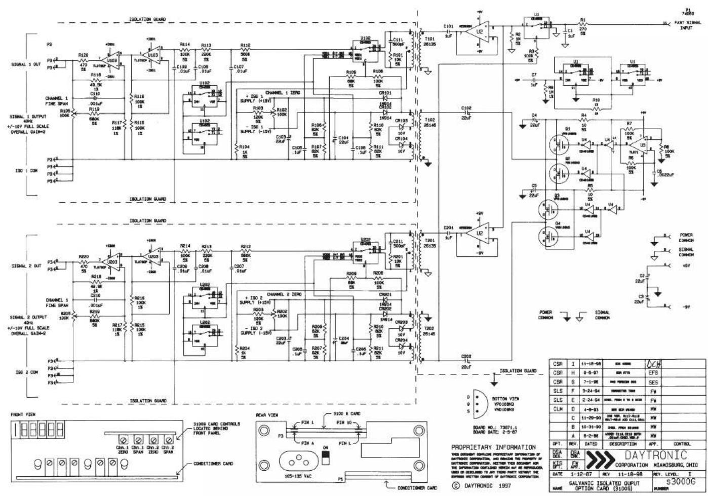
text_image
ISOLATION GUARD P3 P34 P35 R120 U103 R118 49.0K C110 .00uF R119 680K R117 180K R115 100K R113 100K R112 900K C107 .01uF U102 + ISO 1 SUPPLY (+15V) R103 120K - ISO 1 SUPPLY (-15V) R104 1k C105.1uF C106.2uF C107.3uF C108.4uF C109.5uF C110.6uF C111.7uF C112.8uF C113.9uF C114.0uF C115.1uF C116.2uF C117.3uF C118.4uF C119.5uF C120.6uF C121.7uF C122.8uF C123.9uF C124.0uF C125.1uF C126.2uF C127.3uF C128.4uF C129.5uF C130.6uF C131.7uF C132.8uF C133.9uF C134.0uF C135.1uF C136.2uF C137.3uF C138.4uF C139.5uF C140.6uF C141.7uF C142.8uF C143.9uF C144.0uF C145.1uF C146.2uF C147.3uF C148.4uF C149.5uF C150.6uF C151.7uF C152.8uF C153.9uF C154.0uF C155.1uF C156.2uF C157.3uF C158.4uF C159.5uF C160.6uF C161.7uF C162.8uF C163.9uF C164.0uF C165.1uF C166.2uF C167.3uF C168.4uF C169.5uF C170.6uF C171.7uF C172.8uF C173.9uF C174.0uF C175.1uF C176.2uF C177.3uF C178.4uF C179.5uF C180.6uF C181.7uF C182.8uF C183.9uF C184.0uF C185.1uF C186.2uF C187.3uF C188.4uF C189.5uF C190.6uF C191.7uF C192.8uF C193.9uF C200.0kΩ/Ω/Ω/Ω/Ω/Ω/Ω/Ω/Ω/Ω/Ω/Ω/Ω/Ω/Ω/Ω/Ω/Ω/Ω/Ω/Ω/Ω/Ω/Ω/Ω/Ω/Ω/Ω/Ω/Ω/Ω/Ω/Ω/Ω/Ω/Ω/Ω/Ω/Ω/Ω/Ω/Ω/Ω/Ω/Ω/Ω/Ω/Ω/Ω/Ω/Ω/ ISOLATION GUARD P34A P34B P34B(A) P34B(B) P34B(C) P34B(D) P34B(E) P34B(F) P34B(G) P34B(H) P34B(I) P34B(J) P34B(K) P34B(L) P34B(M) P34B(N) P34B(O) P34B(P) P34B(Q) P34B(R) P34B(S) P34B(T) P34B(U) P34B(V) P34B(X) P34B(Y) P34B(Z) P34B(C) P34B(D) P34B(E) P34B(F) P34B(G) P34B(H) P34B(I) P34B(J) P34B(K) P34B(L) P34B(M) P34B(N) P34B(O) P34B(P) P34B(Q) P34B(R) P35A(0)A(0)A(0)A(0)A(0)A(0)A(0)A(0)A(0)A(0)A(0)A(0)A(0)A(0)A(0)A(0)A(0)A(0)A(0)A(0)A(0)A(0)A(0)A(0)A(0)A(0) ISOLATION GUARD P34A(0)A(0)A(0)A(0)A(0)A(0)A(0)A(0)A(0)A(0)A(0)A(0)A(0)A(0)A(0)A(0)A(0)A(0)A(0)A(0) ISOLATION GUARD (CHAMPUL 2 ZERO) + ISO 2 SUPPLY (+15V) + ISO 2 SUPPLY (-15V) + ISO 2 SUPPLY (-25V) + ISO 2 SUPPLY (-35V) + ISO 2 SUPPLY (-45V) + ISO 2 SUPPLY (-55V) + ISO 2 SUPPLY (-65V) + ISO 2 SUPPLY (-75V) + ISO 2 SUPPLY (-85V) + ISO 2 SUPPLY (-95V) + ISO 2 SUPPLY (-105V) + ISO 2 SUPPLY (-115V) + ISO 2 SUPPLY (-125V) + ISO 2 SUPPLY (-135V) + ISO 2 SUPPLY (-145V) + ISO 2 SUPPLY (-155V) + ISO 2 SUPPLY (-165V) + ISO 2 SUPPLY (-175V) + ISO 2 SUPPLY (-185V) + ISO 2 SUPPLY (-195V) + ISO 2 SUPPLY (-205V) + ISO 2 SUPPLY (-215V) + ISO 2 SUPPLY (-225V) + ISO 2 SUPPLY (-235V) + ISO 2 SUPPLY (-245V) + ISO 2 SUPPLY (-255V) + ISO 2 SUPPLY (-265V) + ISO 2 SUPPLY (-275V) + ISO 2 SUPPLY (-285V) + ISO 2 SUPPLY (-295V) + ISO 2 SUPPLY (-305V) + ISO 2 SUPPLY (-315V) + ISO 2 SUPPLY (-325V) + ISO 2 SUPPLY (-335V) + ISO 2 SUPPLY (-345V) + ISO 2 SUPPLY (-355V) + ISO 2 SUPPLY (-365V) + ISO 2 SUPPLY (-375V) + ISO 2 SUPPLY (-385V) + ISO 2 SUPPLY (-395V) + ISO 2 SUPPLY (-405V) + ISO 2 SUPPLY (-415V) + ISO 2 SUPPLY (-425V) + ISO 2 SUPPLY (-435V) + ISO 2 SUPPLY (-445V) + ISO 2 SUPPLY (-455V) + ISO 2 SUPPLY (-465V) + ISO 2 SUPPLY (-475V) + ISO 2 SUPPLY (-485V) + ISO 2 SUPPLY (-495V) + ISO 2 SUPPLY (-505V) + ISO 2 SUPPLY (-515V) + ISO 2 SUPPLY (-525V) + ISO 2 SUPPLY (-535V) + ISO 2 SUPPLY (-545V) + ISO 2 SUPPLY (-555V) + ISO 2 SUPPLY (-565V) + ISO 2 SUPPLY (-575V) + ISO 2 SUPPLY (-585V) + ISO 2 SUPPLY (-595V) + ISO 2 SUPPLY (-605V) + ISO 2 SUPPLY (-615V) + ISO 2 SUPPLY (-625V) + ISO 2 SUPPLY (-635V) + ISO 2 SUPPLY(-645V)- + ISO 2 SUPPLY(-655V)- + ISO 2 SUPPLY(-665V)- + ISO 2 SUPPLY(-675V)- + ISO 2 SUPPLY(-685V)- + ISO 2 SUPPLY(-695V)- + ISO 2 SUPPLY(-705V)- + ISO 2 SUPPLY(-715V)- + ISO 2 SUPPLY(-725V)- + ISO 2 SUPPLY(-735V)- + ISO 2 SUPPLY(-745V)- + ISO 2 SUPPLY(-755V)- + ISO 2 SUPPLY(-765V)- + ISO 2 SUPPLY(-775V)- + ISO 2 SUPPLY(-785V)- + ISO 2 SUPPLY(-795V)- + ISO 2 SUPPLY(-805V)- + ISO 2 SUPPLY(-815V)- + ISO 2 SUPPLY(-825V)- + ISO 2 SUPPLY(-835V)- + ISO 2 SUPPLY(-845V)- + ISO 2 SUPPLY(-855V)- + ISO 2 SUPPLY(-865V)- + ISO 2 Suppvalon (DADYTRONIC CORPORATION KIANISBURG, OHIO)| CSR | I | 11-18-98 | BCE 20000 | OCH |
| CSR | H | 9-5-97 | BCE 9770 | EF8 |
| CSR | 6 | 7-1-96 | BCE VENZON 800 | SES |
| SLS | F | 3-24-94 | CORRECTED 7000 | FN |
| SLS | E | 2-24-94 | DANS. FRANCIS 5 TO 8 AND | FN |
| CLM | D | 4-9-33 | BCE BCR 45400 | MN |
| C | 11-29-90 | CNE WTR. ALICE-FLIXREACH AND CHINA 600 | MN | |
| B | 10-31-90 | BCE FRANCIS 5000 | MN | |
| A | 8-2-98 | ARRED 51/10-015 WITHGROUP DRUG 1 OF | MN | |
| DFT. | REV. | DATED | DESCRIPTION | APP. CONTROL |
| DSA DES. | DSA DES. | DAYTRONIC CORPORATION | MIKANSBURG, OHIO | |
| KTS DFT. | FX DFT. | |||
| DATE | 1-12-67 | REV 11-18-98 | REV. LEVEL. I | |
| GALVANIC ISOLATED OUTPUT NAME OPTION CARD (3100G) | s3000G NUMBER | |||

DAYTRONIC
Daytronic Corporation
Dayton, • (800) 668-4745
www.daytronic.com