2110-2 - Measurement Daytronic - Free user manual and instructions
Find the device manual for free 2110-2 Daytronic in PDF.

User questions about 2110-2 Daytronic
0 question about this device. Answer the ones you know or ask your own.
Ask a new question about this device
Download the instructions for your Measurement in PDF format for free! Find your manual 2110-2 - Daytronic and take your electronic device back in hand. On this page are published all the documents necessary for the use of your device. 2110-2 by Daytronic.
USER MANUAL 2110-2 Daytronic
- Models "2110," "2111," "2112," "2113," "2114," "2115," and "2116" Thermocouple Meters
- Models "2118" and "2119" 100-Ω Platinum RTD Meters
- Model "2160" DC Voltage Meters
- Model "2161" DC Current Meters
- Model "2162" Process Signal (4-20 mA) Meters
- Model "2168" AC (RMS) Voltage Meters
- Model "2169" AC (RMS) Current Meters
- Model "2170" Strain Gage Meters (6-Wire Load Cell)
2. TABLE OF CONTENTS
- ORDERING GUIDE 2
- TABLE OF CONTENTS.... 3
- PRODUCT INTRODUCTION.... 4
- RECEIΩING & UNPACKING 5
- SAFETY CONSIDERATIONS.... 5
- CONNECTOR WIRING INFORMATION 6
- MECHANICAL ASSEMBLY 8
- FRONT PANEL SETUP KEYS 10
- ENABLING & LOCKING OUT MENU ITEMS 12
- READING COORDINATES OF 2 POINTS SCALING METHOD ...... 13
- DC ΩOLTS, AMPS, PROCESS, STRAIN INPUT.... 14
- LOAD CELL & MICROΩOLT INPUT.... 20
- AC RMS ΩOLTS & AMPS INPUT 25
- THERMOCOUPLE INPUT.... 31
- RTD & RESISTANCE INPUT 34
- DUAL & QUAD RELAY OUTPUT OPTIONS 39
- ANALOG OUTPUT OPTION 42
- SERIAL COMMUNICATION OPTIONS 43
- EXCITATION OUTPUT & POWER SUPPLY 48
- INSTRUMENT SETUP ΩIA PC 49
- CUSTOM CURQE LINEARIZATION.... 52
- METER CALIBRATION .... 54
- SPECIFICATIONS....55
- GLOSSARY OF TERMS.... 59
- WARRANTY 64
3. PRODUCT INTRODUCTION
Our digital panel meters are versatile, cost effective solutions to a wide variety of monitoring and control applications. Depending on the choice of signal conditioner, they are easily set up for an accurate display of temperature, pressure, flow, weight, voltage or current, all in appropriate engineering units and with zero and span adjustment when needed. Setup can be via front panel pushbuttons or the meter's serial interface. Selective security lockout of the front panel keys protects against accidental changes to meter setup.
High read rates up to 60 per second (50 for 50 Hz operation) are made possible by Concurrent Slope Conversion (Pat 5,262,780), which integrates the signal over an AC power line cycle for maximum noise rejection. High read rates provide accurate peak and valley capture, and quick response for control applications. An adaptive digital filter supplies a time constant for the encountered signal noise level, yet responds rapidly to changes that exceed a selected threshold. Self-calibration occurs automatically after every 17th reading.
The standard power supply is a high-efficiency switching unit that operates from AC or DC, and allows the meters to be powered from worldwide AC without changes. A low-voltage supply is optional for power from 10-48Ω batteries or from 12-30 Ωac. Both supplies provide an isolated 5, 10 or 24Ωdc transducer excitation output.
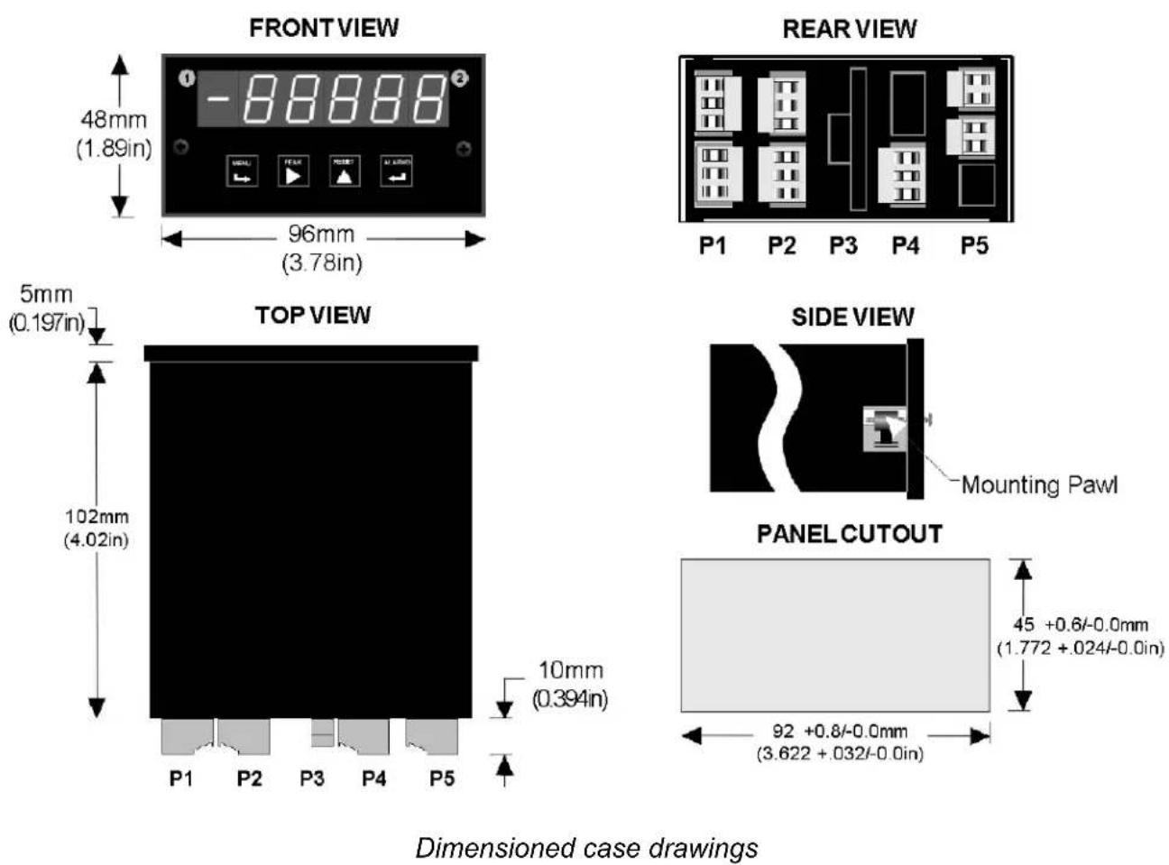
The meter case conforms to the 1/8 DIN size standard. It is made of high impact, 94Ω-0 UL-rated plastic and is watertight to NEMA-4 (IP65) when panel mounted. Mounting is from the front of the panel and requires less than 110 mm behind the panel. Power and signal wiring is via removable plugs conforming to UL61010C safety standards. All output options are isolated from meter and power ground to 250 Ωac.
Extended meter versions can linearize nonlinear inputs. Up to 180 data points may be linearized by a computer program that stores setup parameters in nonvolatile memory. Extended meters can also display rate of change, for example to display flow rate based on changing tank level.
Alarm or setpoint control is provided by an optional relay board with two or four Form C 8A mechanical relays or two or four Form A 120 mA solid state relays. The setpoints may be latching or non-latching, be energized above or below the setpoint, or operate in a fail-safe mode. The relays can operate from the filtered signal to reduce relay chatter or from the unfiltered signal for fastest response. Snubber circuits and a programmable relay switching time delay extend relay contact life.
An isolated analog output of 4-20 mA, 0-20 mA, 0-10Ω or -10 to +10Ω can be provided by an optional analog output board. The output is linearized to the display and can operate from the filtered or unfiltered signal input. It can be scaled via front panel pushbuttons or the meter's serial interface.
USB, RS232, or RS485 (2-wire half-duplex or 4-wire full-duplex) serial communications options are available with the Modbus protocol or a simpler custom ASCII protocol. Modbus operation includes RTU or ASCII modes, up to 247 digital addresses, and up to 32 devices per RS485 line without a repeater. USB-to-RS485 converter boards allow a meter to be interfaced to a PC and to multiple meters on an RS485 network.
Meter programming can be via the meter's front panel or a PC running Windows based Instrument Setup Software (serial interface option required).
4. RECEIVING & UNPACKING
Your meter was carefully tested and inspected prior to shipment. Should the meter be damaged in shipment, notify the freight carrier immediately. In the event the meter is not configured as ordered or the unit is inoperable, return it to the place of purchase for repair or replacement. Please include a detailed description of the problem.
5. SAFETY CONSIDERATIONS

Warning: Use of this equipment in a manner other than specified may impair the pro-on of the device and subject the user to a hazard. isually inspect the unit for signs of age. If the unit is damaged, do not attempt to operate.
Caution:
- The unit must be connected to a Disconnect switch or a branch-circuit breaker, which must be in a suitable location
- This unit must be powered by 85-264 Ωac with the high voltage power supply option, or 10-48 Ωdc (12-32 Ωac) with the low voltage power supply option. Ωerify that the proper power option is installed for the power to be used. This meter has no On/Off switch. It will be in operation as soon as power is connected.
- The 85-264 Ωac power connector (P1 Pins 1-3) is colored Green to differentiate it from other input and output connectors. The 12-32 Ωac (10-48 Ωdc) power connector is colored Black.
- Do not make signal wiring changes or connections when power is applied to the instrument. Make signal connections before power is applied. If reconnection is required, disconnect power before such wiring is attempted.
- To prevent electrical or fire hazard, do not expose the instrument to excessive moisture.
- Do not operate the instrument in the presence of flammable gases or fumes; such an environment constitutes a definite safety hazard. This meter is designed to be mounted in a metal panel or a bench or wall mount style case. The spacing around the meter and the ventilation must be sufficient to maintain the ambient temperature at less than 55^ C.
- erify the panel cutout dimensions, and mount according to instructions.
Symbols used

Caution (refer to accompanying documents) ⊥ Earth (ground) terminal.

Caution, risk of electric shock. Both direct and alternating current.

Equipment protected throughout by double insulation or reinforced insulation.
Operating environment:
The meter is Class II (double insulated) equipment designed for use in Pollution degree 2.
6. CONNECTOR WIRING INFORMATION
CONNECTORS
Connectors for signal and power are UL-rated screw-clamp terminal blocks that plug into mating jacks on the printed circuit board.
Communication connectors are a single RJ11 plug for RS232, dual RJ11 plugs for RS485, dual RJ45 plugs for RS485 Modbus, or USB.
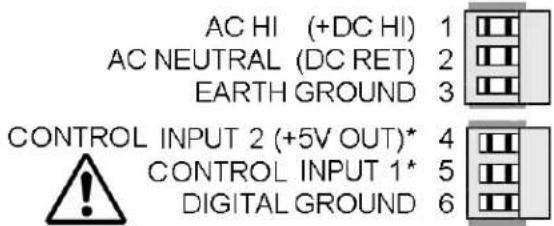
P1 - POWER AND DIGITAL CONTROLS
text_image
AC HI (+DC HI) 1 AC NEUTRAL (DC RET) 2 EARTH GROUND 3 CONTROL INPUT 2 (+5V OUT)* 4 CONTROL INPUT 1* 5 DIGITAL GROUND 6Warning: Hazardous voltages may be present on pins 4, 5 & 6 of P1 since digital ground is tied to pin 3 of P5 (-Signal Input). Keep pin 3 close to earth ground to minimize common mode voltage or shock hazard at pins 4, 5 & 6 of P1.
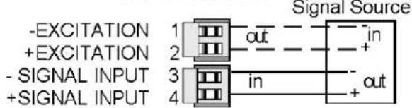
P5 - SIGNAL INPUT
DC & PROCESS
text_image
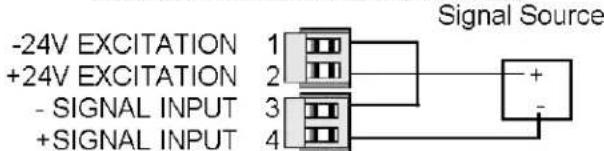
-EXCITATION 1 +EXCITATION 2 - SIGNAL INPUT 3 + SIGNAL INPUT 4 Signal Source out in + - in out2 WIRE PROCESS TRANSMITTER
text_image
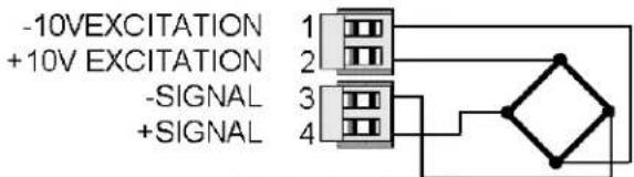
-24V EXCITATION 1 +24V EXCITATION 2 - SIGNAL INPUT 3 + SIGNAL INPUT 4 Signal SourceSTRAINGAUGE
text_image
-10V EXCITATION +10V EXCITATION -SIGNAL +SIGNALAC (TRUE RMS)

text_image
SIGNAL HIGH 1 2,20,200,600V INPUTS NC 2 SIGNAL LOW 3 AC NEUTRAL SIGNAL HIGH 4 0.2V, CURRENT INPUTS
text_image
P1 1 P2 1 P3 6 A 1 P4 1 P5 6 6 6 B 1 1 3 6Note: Control inputs 1 & 2 of P1 are menu selectable.
LOAD CELL METER

text_image
-10 V EXCITATION 1 -SENSE 2 -SIGNAL 3 +SIGNAL 4 +10 V EXCITATION 5 +SENSE 6 J5RTD & OHMS (2-WIRE)
text_image
- EXCITATION 1 + EXCITATION 2 - SIGNAL INPUT 3 + SIGNAL INPUT 4RTD & OHMS (3-WIRE)
text_image
- EXCITATION 1 + EXCITATION 2 - SIGNAL INPUT 3 + SIGNAL INPUT 4RTD & OHMS (4-WIRE)
text_image
- EXCITATION 1 + EXCITATION 2 - SIGNAL INPUT 3 + SIGNAL INPUT 4THERMOCOUPLE
text_image
- SIGNAL INPUT + SIGNAL INPUTP2 - SETPOINT CONTROLLER
DUAL MECHANICAL RELAY OUTPUTS
| ALARM 1 | N/O CONTACT |
| ALARM 1 | COMMON |
| ALARM 1 | N/C CONTACT |
| ALARM 2 | N/O CONTACT |
| ALARM 2 | COMMON |
| ALARM 2 | N/C CONTACT |

QUAD MECHANICAL RELAY OUTPUTS
| ALARM 1 | N/O CONTACT |
| ALARM 1 & 2 | COMMON |
| ALARM 2 | N/O CONTACT |
| ALARM 3 | N/O CONTACT |
| ALARM 3 & 4 | COMMON |
| ALARM 4 | N/O CONTACT |
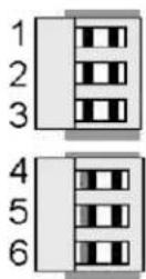
P3 - SERIAL COMMUNICATIONS
RS232 INTERFACE

Computer

text_image
6 5 4 3 2 1 GND TX RX RTSRS485 INTERFACE - FULL DUPLEX

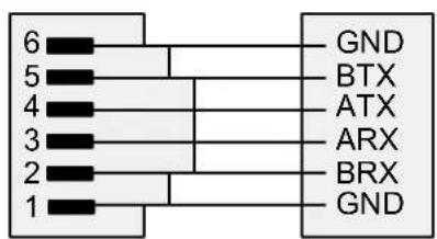
text_image
6 5 4 3 2 1 GND BTX ATX ARX BRX GNDDUAL SOLID STATE RELAY OUTPUTS
| ALARM 1 | 1 | DC OR AC |
| ALARM 1 | 2 | NOT USED |
| ALARM 1 | 3 | DC OR AC |
| ALARM 2 | 4 | DC OR AC |
| ALARM 2 | 5 | NOT USED |
| ALARM 2 | 6 | DC OR AC |
QUAD SOLID STATE RELAY OUTPUTS
| ALARM 1 | N/O CONTACT |
| ALARM 1 & 2 | COMMON |
| ALARM 2 | N/O CONTACT |
| ALARM 3 | N/O CONTACT |
| ALARM 3 & 4 | COMMON |
| ALARM 4 | N/O CONTACT |

P4 - ANALOG OUTPUT
UNIPOLAR CONNECTIONS

text_image
4-20 mA or 0-20 mA OUTPUT 0-10V OUTPUT ISOLATED GROUND
BIPOLAR CONNECTIONS

text_image
REFERENCE or RETURN -10V to +10V OUTPUT N/C
RS485 INTERFACE - HALF DUPLEX
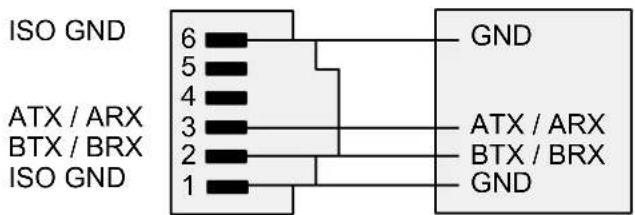
text_image
ISO GND 6 5 4 3 2 1 ATX / ARX BTX / BRX ISO GND GND ATX / ARX BTX / BRX GNDRS485-MODBUS - FULL DUPLEX RS485-MODBUS - HALF DUPLEX
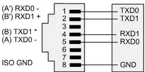
text_image
(A') RXD0 - (B') RXD1 + (B) TXD1 * (A) TXD0 - ISO GND 1 2 3 4 5 6 7 8 TXD0 TXD1 RXD1 RXD0 GND
text_image
(B) TX / RXD1 (A) TX / RXD0 ISO GND 1 2 3 4 5 6 7 8 (B) TX/RXD1 (A) TX/RXD0 GND7. MECHANICAL ASSEMBLY
REMOVING THE REAR PANEL
First remove any connectors. Use one hand to press in the two sides of the rear of the case, and the other hand to press down the two protruding tab releases at the top of the rear panel (see figure below). This will unhook the rear panel from the case.

text_image
Retaining tab with tab release Retaining tab Rear Panel Retaining tab with tab release Retaining tabREMOVING THE ELECTRONICS
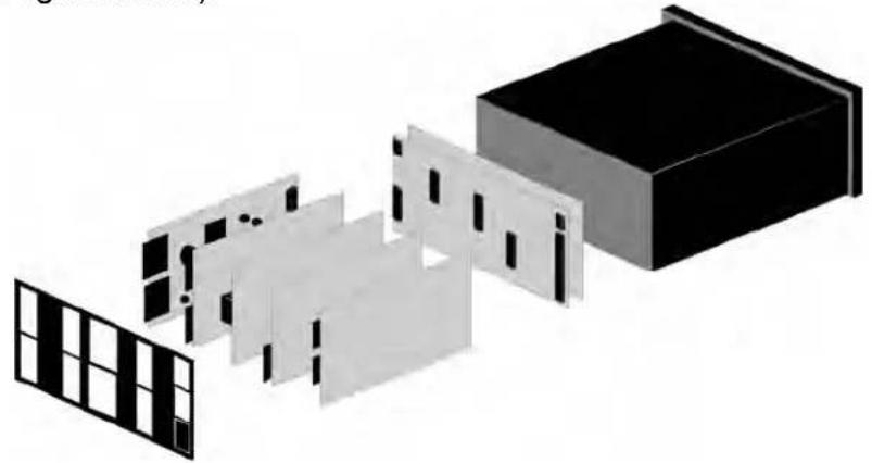
With the rear panel removed, grasp the power supply board to the left and signal conditioner board to the right, and carefully slide the electronic assembly out through the rear of the case. (see figure below).
natural_image
Exploded view diagram of a building with internal components and window patterns (no text or symbols)INSTALLING NEW OPTION BOARDS
Options boards plug into the main board at the front of the meter. These are plug-and-play and may be installed in the field. They will be recognized by the software, which will provide access to the menu items associated with that board. If necessary, remove rear panel knockouts for new boards. Boards plug into connectors as follows:
| Option Board Main Board | Plug Rear Panel Jack | |
| Power supply | P11 | J1 |
| Relay board | P12 | J2 |
| Serial interface board | P13 | J3 |
| Analog output board | P14 | J4 |
| Signal conditioner board | P15 | J5 |
Note: Corresponding main board and option board connectors have the same number of electrical lines. When an option board is correctly installed, the top and bottom edges of the main board and option board are aligned.
REASSEMBLING YOUR METER
Slide the electronics assembly into the case until the display board is seated flush against the front overlay. Insert the bottom tabs of the rear panel into the case, and then carefully align the board connectors with the openings in the rear panel. If necessary, remove any rear panel knockouts for new option boards that may have been installed. Ensure that all option boards are properly aligned with the molded board retaining pins on the inside of the rear panel. Once the rear panel is in place, reinstall the input/output screw clamp terminal plugs.
PANEL MOUNTING
Ensure that the panel mounted gasket is in place against the back of the bezel. Turn the two mounting screws counterclockwise until the space between the mounting pawl and the rear of the gasket is greater than the panel thickness. Insert the meter in the panel cutout. Turn the mounting screws clockwise until the meter is securely mounted in the panel. Do not overtighten.
8. FRONT PANEL SETUP KEYS
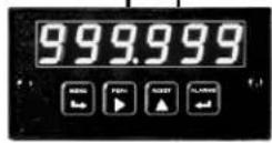
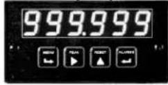
text_image
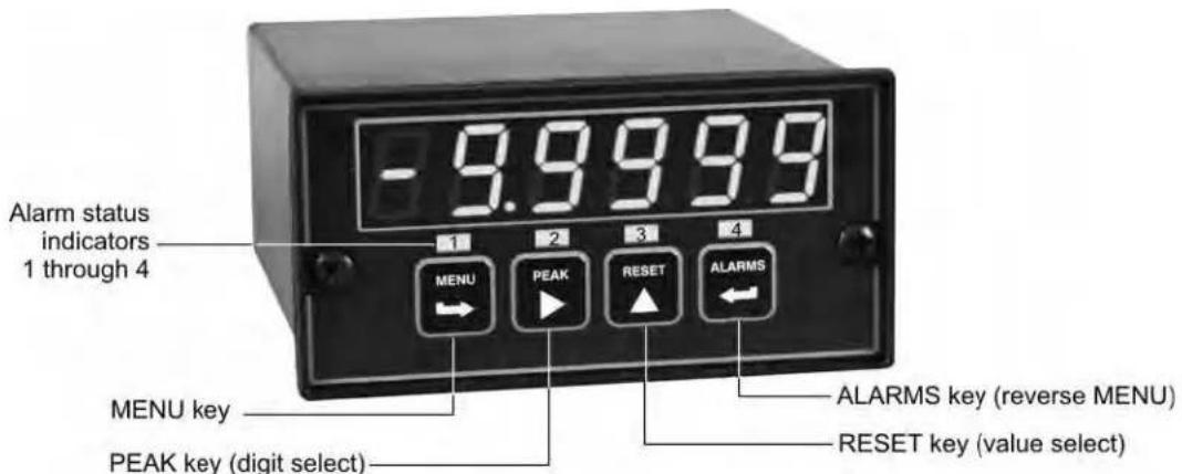
-9.9999 Alarm status indicators 1 through 4 MENU PEAK RESET ALARMS MENU key PEAK key (digit select) ALARMS key (reverse MENU) RESET key (value select)Meter Front Panel
There are four front panel keys, which change function for the Run Mode and Menu Mode, effectively becoming eight keys. The keys are labeled with alphanumeric captions (MENU, PEAK, RESET, ALARMS) for the Run Mode and with symbols (right arrow, right triangle, up triangle, left arrow) for the Menu Mode.
FRONT PANEL LOCKOUT
The Menu Mode will not work with most meters as received from the factory, since all menu items have been disabled in software and a lockout jumper is in place. That jumper needs to be removed for the Menu Mode to work, and menu items under Loc 1, Loc 2 and Loc 3 then need to be set to "0" via the front panel for these menu items to be unlocked See Section 9. The paragraphs below assume that all menu items have been unlocked.
MENU MODE KEY ACTION
In the Menu Mode, pressing a key momentarily advances to the next menu item. Holding down a key automatically advances through multiple menu items for fast menu navigation.
KEYS IN RUN MODE

MENU Key. Pressing MENU from the Run Mode enters the Menu Mode. Pressing MENU repeatedly will step the meter through the various menu items (if these have not been locked out) and then back to the Run Mode.

PEAK Key. Pressing PEAK normally causes the peak value of the input signal to be displayed. The peak display then blinks to differentiate it from the normal present value display. Pressing PEAK again returns the display to the present value. The PEAK key can also be programmed to display alley, alternating Peak or alley, or to Tare the reading to zero. When Peak or alley is selected, periodic horizontals bars at the top of the display indicate Peak, and periodic horizontals bars at the bottom indicate alley.

RESET Key. Pressing RESET with PEAK resets peak and valley values. Pressing RESET with ALARMS resets latched alarms. Pressing RESET with MENU performs a meter reset (same as power on). Meter reset can also be applied via a rear panel connect or a serial ASCII command.

ALARMS Key. Pressing ALARMS once displays the setpoint for Alarm 1. Pressing it again displays the setpoint for Alarm 2. Pressing it again returns to the present value.
KEYS IN MENU MODE

Right Arrow Key (MENU). Pressing Steps the meter through all menu items that have been enabled and then back to the Run Mode. With the DC signal conditioner board and no option boards, available menu items are InPut, SEtuP, ConFG, FiLtr, dEc.Pt, SCALE, OFFst, Loc 1, Loc 2, Loc 3. If a change has been made to a menu item, that change is saved to non-volatile memory when the key is pressed next, and StoreE is displayed briefly.

Right Triangle Key (Digit Select).
- Pressing ▶ from the InPut menu brings up all meter functions available with the meter's signal conditioner. For the DC signal conditioner, these are dC U, dC A and rAtio.
- Pressing ▶ from the SETuP, ConfFG, FiLtr, SCALE, OFFSt, Loc 1, Loc 2 or Loc 3 menus items sequentially selects digit positions 1 - 5, as indicated by a flashing digit: 00000, 00000, 00000, 00000, 00000.
- Pressing ▶ from the dEC.Pt menu item sequentially selects decimal point positions, which will flash: d.dddd dd_ddd ddd_dd dddd_d ddddd_ ddddd.

Up Triangle Key (Value Select). Pressing ▲ for a flashing item (digit position or decimal point position) will increment that item. Pressing MENU will save any changes.

Left Arrow Key (Reverse Menu). Pressing ← has the same effect as the MENU key, except that menu items are brought up in reverse order.
9. ENABLING & LOCKING OUT MENU ITEMS
For security reasons and ease of meter operation, any and all menu items may be disabled or "locked out" so that they are no longer directly accessible from the front panel. Each function to be disabled is set to "1" in menu items Loc 1, Loc 2 or Loc 3, and each function to be enabled is set to "0." The top menu items Loc 1, Loc 2 and Loc 3 can in turn be locked out by installing an internal hardware jumper. With the jumper installed, the operator only has access only to enabled menu items. With the jumper removed, the operator also has access to menu items Loc 1, Loc 2 and Loc 3.
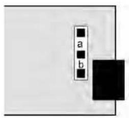
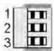
SETTING HARDWARE LOCKOUT JUMPER
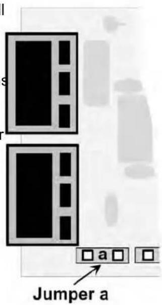
To access the lockout jumper, remove the rear panel per Section 9 and locate jumper "a" in the lower portion of the power supply board next to the input connectors (see figure at right).
text_image
Jumper aSETTING SOFTWARE LOCKOUTS
When setting up the meter, it may be necessary to enable specific menu items by setting the corresponding lockout digit to 0. Be sure to reset the lockout digit to "1" if you do not want the menu item to be changed by an operator.
Loc 1 Loc 2 Loc 3
Press the → MENU key until Loc 1, Loc 2 or Loc 3 is displayed, as desired. Note: the hardware lockout jumper must be removed (see above).
11111
Press ▶to display the lockout status, consisting of 1's and 0's. The left digit will flash. Press ▶gain to step to the next digit, which will flash.
00000
12345
Press ▲ to set the flashing digit to "0" to enable the menu item or to "1" to disable. Press MENU to enter. See the table to the right for list of menu items that can be enabled or disabled.
Enabled or Disabled Menu Items
Loc 1
1 - Input type selection.
2 - Meter setup, configuration & decimal pt.
3 - Filter selection.
4 - Scale or Lo, Hi input.
5 - Offset or Lo, Hi reading
Loc 2
2 - Alarm setup.
3 - Alarm setpoint value programming.
4 - Analog output scaling.
5 - Serial interface setup.
Loc 3
2 - Ωiew peak value
3 - Ωiew alarm setpoints
4 - Reset (peak & latched alarms)
5 - Reset (meter reset)
10. READING COORDINATES OF 2 POINTS SCALING METHOD
When the reading coordinates of 2 points scaling method has been selected under SEtuP, the four menu items below will appear ahead of all other menu items when the MENU or key is first pressed from the run mode.
This scaling method applies a straight line fit between two points, which are determined from actual transducer signals and the desired corresponding meter readings. A low signal, such as the output of a pressure transducer at zero pressure, and high signal, such as the output of the same transducer at a known high pressure, are applied to the meter. The desired corresponding low and high readings are then entered from the front panel. The meter then applies straight line fit between the high and low calibration points. This scaling method has the advantage of calibrating the transducer and meter as a system. The actual voltage or current at either point does not need to be known. This method is ideal for process and load cell meters, which require zero and span adjustment. It is also available for DC or AC meters. It is not available with thermocouple or RTD meters.
The programming example below is for a process meter used with a 4-20 mA pressure transducer for 0 to 100 psi. Decimal points are set separately using the dEC.Pt menu.
 | Press Menu Select Key |  | Press Digit Select Key |  |  | Value Select |
 | Apply low signal input (e.g., transducer output for 0 psi). |  | Press ▶to display reading at low signal input (e.g., 4.021 mA). |  |  | ▲to store low reading. |
 | Apply high signal input (e.g., transducer output for known 100.00 psi source). |  200.94 200.94 | Press ▶to display reading at high signal input (e.g., 20.094 mA). |  |  | ▲to store high reading. |
 Mode to enter desired low reading (e.g., 0.00). Mode to enter desired low reading (e.g., 0.00). |  |  |  |  |  | |
 |  |  |  | |||
| to flash. | flashing first digit, 0 thru 9 for other flashing digits. | |||||
  | to enter desired high ng (e.g., 100.00). |  |  |  |  |  |
 |  |  |  |  | ||
| to flash. |  |  | ||||
 | ||||||
| other flashing digits. | ||||||
11. DC VOLTS, AMPS, PROCESS, STRAIN INPUT
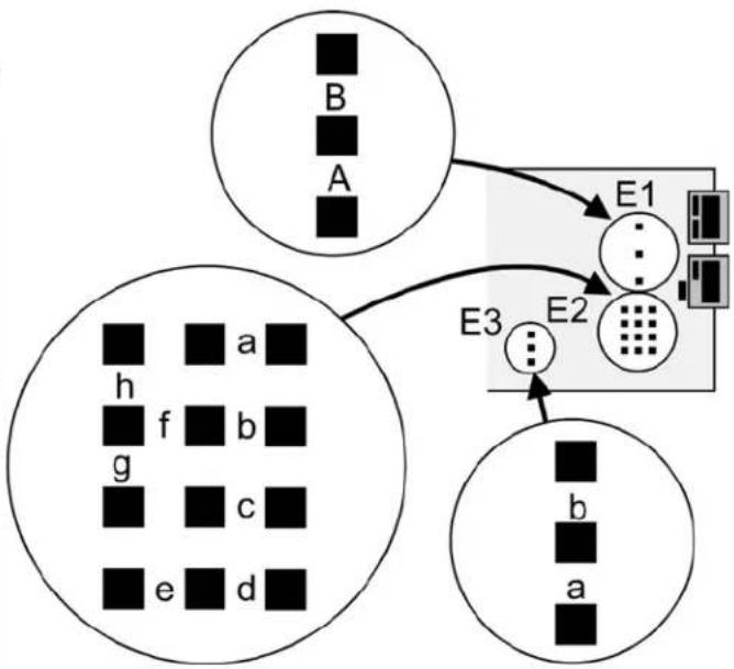
The DC Ωolts, Amps, Process and Strain meters utilize the DC signal conditioner board, which needs to be configured via jumpers for the desired voltage or current range. All signal ranges are factory calibrated with calibration factors stored in EEPROM. The meter software recognizes the board and will bring up the appropriate menu items for it; however, it does not recognize the jumper settings. Please see further manual sections for setup of the following: relay output (16), analog output (17), communications (18), and excitation output (19).
Board Revision N
| Voltage Ranges | Jumpers | ||
| FS Input E1 | E2 E3 | ||
| ±200.00 mΩ | A | f | b |
| ±2.0000 Ω | A | f | a |
| ±20.000 Ω | B | h | b |
| ±200.00 Ω | B | h | a |
| ±300Ω (UL) | B | g | a |
| ±600Ω (not UL) | B | g | a |
| Current Ranges | Jumpers | ||
| FS Input E1 | E2 E3 | ||
| ±2.0000 mA | A | e, g | b |
| ±20.000 mA | A | d, g | b |
| ±200.00 mA | A | c, g | b |
| ±5.000 A | A | a, b, g | b |
flowchart
graph TD
    A["Circle A"] --> E1["Central Block"]
    B["Circle B"] --> E1
    C["Circle C"] --> E2["Device"]
    D["Circle D"] --> E2
    E1 --> E3["Output"]
    E2 --> E3
    style A fill:#fff,stroke:#000
    style B fill:#fff,stroke:#000
    style C fill:#fff,stroke:#000
    style D fill:#fff,stroke:#000
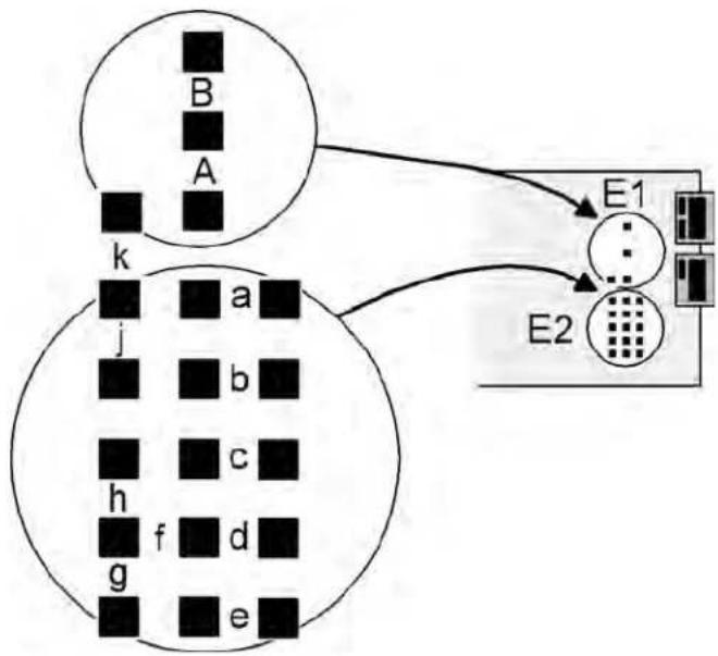
Board Revision P (shipped between 15 Jan 2012 and 1 May 2012)
Voltage Ranges Jumpers
| FS Input E1 | E2 | |
| ±200.00 mΩ | A | f |
| ±2.0000 Ω | B | k |
| ±20.000 Ω | B | j |
| ±200.00 Ω | B | h |
| ±300Ω (UL) | B | g |
| ±600Ω (not UL) | B | g |
Current Ranges Jumpers
| FS Input E1 | E2 | |
| ±2.0000 mA | A | e, g |
| ±20.000 mA | A | d, g |
| ±200.00 mA | A | c, g |
| ±5.000 A | A | a, b, g |
flowchart
graph TD
    subgraph_Generation_A["Generation A"]
        B["B"] --> k["k"]
        A["A"] --> k["k"]
        k["k"] --> j["j"]
        j["j"] --> h["h"]
        h["h"] --> g["g"]
        g["g"] --> e["e"]
    end
    subgraph_Generation_B["Generation B"]
        E1["E1"] --> E2["E2"]
    end
    E2["E2"] --> E1["E1"]
    E1["E1"] --> E2["E2"]
Board Revisions Q and R
Voltage Ranges
Jumpers
| FS Input E1 | E2 E3 | ||
| ±200.00 mΩ | A | f | b |
| ±2.0000 Ω | A | f | a |
| ±20.000 Ω | B | h | b |
| ±200.00 Ω | B | h | a |
| ±300Ω (UL) | B | g | a |
| ±600Ω (not UL) | B | g | a |
Current Ranges
Jumpers
| FS Input E1 | E2 E3 | ||
| ±2.0000 mA | A | e, g | b |
| ±20.000 mA | A | d, g | b |
| ±200.00 mA | A | c, g | b |
| ±5.000 A | A | a, b, g | b |

flowchart
graph TD
    E3["Block E3"] --> G1["Grid"]
    G1 --> H1["Block H1"]
    H1 --> E1["Block E1"]
    E1 --> E2["Block E2"]
    E2 --> B["Block B"]
    E2 --> A["Block A"]
    E2 --> h["Block h"]
    E2 --> g["Block g"]
    E2 --> b["Block b"]
    E2 --> f["Block f"]
    E2 --> c["Block c"]
    E2 --> e["Block e"]
    E2 --> d["Block d"]
- Letters indicate jumper position. Jumpers are installed on pins adjacent to letters.
- Use 5 mm (0.2") jumpers for locations designated by a capital letter.
- Use 2.5 mm (0.1") jumpers for locations designated by a lower case letter.
- Store spare jumpers on an unused jumper post not associated a capital letter.
SCALE & OFFSET SETUP
For DC voltmeters & ammeters, a scale factor of 1 and an offset of 0 are used for direct readings in (milli)volts or (milli)amperes. Decimal point selection does not affect the displayed digits. For example, 0-20Ω or 0-20 mA signals can both be displayed as 0-20000. A full scale of 20000 may be displayed as 20.000 mA or 20000 μA. Use with a current shunt will require a scale factor to be set. For example, for a 500-100 (500A, 100 mΩ) shunt, divide 5000 (the desired full scale display with 0.1A resolution) by 10000 (displayed value with 100 mΩ when the scale factor is 1.0) for a scale factor of 0.5.
For process & strain meters, scaling is normally set up from the front panel using the ▶ and ▲ keys, but can also be set up via RS232/485 using special PC-compatible setup software (available at no charge). The meter allows three scaling methods to be selected: 1) Scale and offset, 2) Coordinates of 2 points, and 3) Reading coordinates of 2 points. Only menu items applicable to the selected method will be presented.
KEYSTROKES FOR SETUP
If the MENU ↩ key does not work, see Section 9 "Enabling & Locking Out Menu Items."
| MENU→Press MenuSelect Key | PEAK▶Press DigitSelect Key | RESET▲Press Value SelectKey |
| InPutSelection of signal input type & range | dC UDC Ωolts | 0.2U 2.0U 20.0U 200.0U 600.0U0.2, 2, 20, 200, 660Ω FS |
| dC ADCAmps | 2.0a 20.0a 200.0a 5.0a0.2, 20, 200 mA, 5A FS | |
| rAtioStrain gauge & ratio | 0.2U 2.0U 20.0U0.2, 2, 20Ω FS. | |
| SEtuPMeter Setup | 00_00Display selection with scale factor of 1. | 0 4-1/2 digits (±20,000)1 Remote display (±99,999)2 4-1/2 digits, counts by 10 (±20,000)3 3-1/2 digits (±2,000) |
| 00_00Power line frequency | 0 Noise minimized for 60 Hz1 Noise minimized for 50 Hz | |
| 00_00Scaling method | 0 Scale and offset method1 Coordinates of 2 points method2 Reading coordinates of 2 points method | |
| 00_00Control inputs 1 & 2:True = logic 1 (0Ω or tied to digital ground)False = logic 0 (5Ω or open) | 0 1 = Reset, 2 = Meter Hold1 = Function Reset, 2 = Peak or Ωalley2 1 = Hold, 2 = Peak or Ωalley Display3 1 = Hold, 2 = Tare4 1 = Peak or Ωalley Display, 2 = Tare5 1 = Tare, 2 = Reset6 1 = 1, 2 = 1, decimal point = XXXXX1 = 0, 2 = 1, decimal point = XXXX.X1 = 1, 2 = 0, decimal point = XXX.XX1 = 0, 2 = 0, decimal point = XX.XXX7 1 = 1, 2 = 1, decimal point = XXXX.X1 = 0, 2 = 1, decimal point = XXX.XX1 = 1, 2 = 0, decimal point = XX.XXX1 = 0, 2 = 0, decimal point = X.XXX8 1 = Function Reset, 2 = Display Blank9 1 = Hold, 2 = Display BlankA 1 = Peak or Ωalley, 2 = Display BlankB 1 = Tare, 2 = Display BlankC 1 = Ωalley Display, 2 = Peak DisplayD 1 = Tare, 2 = Reset Tare to ZeroBoth inputs 1 and 2 set to logic 1 for selections2,4,A,C= Function ResetBoth inputs 1 and 2 set to logic 1 for selections0,1,3,5,8,9,E,D= Meter Reset | |
 Press Menu Select Key Press Menu Select Key |  Press Digit Select Key Press Digit Select Key |  Press Value Select Key Press Value Select Key |
 Meter Configuration Meter Configuration |   | -HT2W-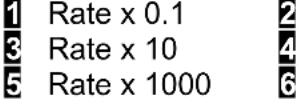 -Rate x 1Rate x 100Rate x 10000 -Rate x 1Rate x 100Rate x 10000 |
  | -  | |
 Auto-tare Auto-tare |  | |
  |  | |
 Filtering Filtering |   | -Z85X] |
 Peak & Ωalley filtering Peak & Ωalley filtering |  | |
  |  | |
 |  | |
  | - - - - - - - - - - - - - | |
 Dec. point selection Dec. point selection |  Decimal point flashes. Decimal point flashes. |         |
| MENU→Press MenuSelect Key | PEAK▶Press DigitSelect Key | RESET▲Press Value SelectKey |
| Scaling method “Scale and Offset” if selected underSEtup | ||
| SCALEScale factor | 0.0000 0.0000 0.00000.0000 0.0000 0.0000Select digit to flash. | Select -9 thru 9 for flashing first digit, 0 thru 9 for other flashing digits. Select decimal point location when decimal point is flashing. |
| OFFstOffset value | 0.0000 0.0000 0.00000.0000 0.0000Select digit to flash. | Select -9 thru 9 for flashing first digit, 0 thru 9 for other flashing digits. Decimal point location is selected bydEC.Pt. |
| Scaling method “Coordinates of 2 points” if selected underSEtup | ||
| Lo InLow signal input. | 0.0000 0.0000 0.00000.0000 0.0000Select digit to flash. | Select -9 thru 9 for flashing first digit, 0 thru 9 for other flashing digits. Decimal point is set by input range chosen. |
| LordDesired reading at Lo In. | 0.0000 0.0000 0.00000.0000 0.0000Select digit to flash. | Select -9 thru 9 for flashing first digit, 0 thru 9 for other flashing digits. Decimal point is set bydEC.Pt. |
| Hi InHigh signal input. | 0.0000 0.0000 0.00000.0000 0.0000Select digit to flash. | Select -9 thru 9 for flashing first digit, 0 thru 9 for other flashing digits. Decimal point is set by input range chosen. |
| HirdDesired reading at Hi In. | 0.0000 0.0000 0.00000.0000 0.0000Select digit to flash. | Select -9 thru 9 for flashing first digit, 0 thru 9 for other flashing digits. Decimal point is set bydEC.Pt. |
| Scaling method “Reading coordinates of 2 points” if selected underSEtup | ||
| Lo InLow signal input. | 0.021Apply a low reference signal to the meter. | 0.021Press ▲ to store the low signal input in the meter. |
| Hi InHigh signal input. | 20.094Apply a high reference signal to the meter. | 0.021Press ▲ to store the high signal input in the meter. |
| LordDesired reading at Lo In. | 0.0000 0.0000 0.00000.0000 0.0000Select digit to flash. | 0.0000Select -9 thru 9 for flashing first digit, 0 thru 9 for other flashing digits. Decimal point is set bydEC.Pt. |
| HirdDesired reading at Hi In. | 0.0000 0.0000 0.00000.0000 0.0000Select digit to flash. | 6.7500Select -9 thru 9 for flashing first digit, 0 thru 9 for other flashing digits. Decimal point is set bydEC.Pt. |
| Option board dependent menu items |
| ALSEt ALS34 dEU1H dEU2H dEU1b dEU2b dEU3H DEU4H DEU3b DEU4bMenu items related to alarm setup These will only appear if a relay board is detected. If so, please see Section16. |
| AnSEt An Lo An HiMenu items related to analog output setup. These will only appear if an analog output board is detected. If so, see Section 17. |
| SEr 1 SEr 2 SEr 3 SEr 4 AddrMenu items related to serial communications. These will only appear if an RS232, RS485 or USB I/O board is detected. If so, see Section 18. |
| Menu lockout items |
| Loc 1 Loc 2 Loc 3Menu items used to enable or lock out (hide) other menu items. Loc menu items may in turn be locked out by a hardware jumper. Please see Section 9. |
* Scaling method 2, “Reading Coordinates of 2 Points Scaling Method,” will appear before all other Menu items, including InPut Decimal point is set by dEC.Pt.
12. LOAD CELL & MICROVOLT INPUT
The Load Cell and Microvolt meters utilize the load cell signal conditioner board, which offers sensitivity to ±20 m full scale and 4 or 6-wire load cell connection. This board needs to be configured via jumpers for the desired voltage range. All signal ranges are factory calibrated with calibration factors stored in EEPROM. The meter software recognizes the board and will bring up the appropriate menu items for it; however, it does not recognize the jumper settings. Please see further manual sections for setup of the following features: relay output (16), analog output (17), communications (18), and transducer excitation output (19).
Ranges & Display with Scale Factor = 1
| Input Jumpers | Full scale display | |
| ±20 mΩ | e | ±20000 |
| ±50 mΩ | a | ±50000 |
| ±100 mΩ | b | ±10000 |
| ±250 mΩ | c | ±25000 |
| ±500 mΩ | d | ±50000 |

flowchart
graph TD
    A["a"] --> B["b"]
    C["d"] --> D["c"]
    E["e"] --> F["e"]
    style A fill:#f9f,stroke:#333
    style B fill:#ccf,stroke:#333
    style C fill:#ccf,stroke:#333
    style D fill:#ccf,stroke:#333
    style E fill:#cfc,stroke:#333
    style F fill:#fcc,stroke:#333
Notes 1. See Section 19 to select 10Ω excitation.
- Jumpers are 2.5 mm (0.1 in).
SCALE & OFFSET SETUP
For DC microvolt meters, a scale factor of 1 and an offset of 0 are used for direct readings in microvolts or millivolts. Decimal point selection does not affect the displayed digits. For example, 20 mΩ can be displayed as 20.000 mΩ or 20000 μΩ. The decimal point is set separately.
For load cell applications, scaling is normally set up from the front panel using the ▶ and ▲ keys, but can also be set up via RS232/485 using special PC-compatible setup software (available at no charge). The meter allows three scaling methods to be selected: 1). Manual scale and offset, 2) Coordinates of 2 points, and 3) Reading coordinates of 2 points. Please see the Glossary for an explanation of each method.
KEYSTROKES FOR SETUP
If the MENU key does not work, see Section 9 "Enabling & Locking Out Menu Items."
| MENUPress MenuSelect Key | PEAKPress DigitSelect Key | RESETPress Value SelectKey |
| InPutSelection of signal input type & range | StrnStrain or ratiometric | 20.0 50.0 100.0 250.0 500.020, 50, 100, 250, 500 mΩ FS voltage |
| dC uDC millivolts | 20.0 50.0 100.0 250.0 500.020, 50, 100, 250, 500 mΩ FS voltage | |
| SEtupMeter Setup | 00_00Display type | 0 4-1/2 digit meter, counts by 11 5-digit remote display (±99,999)2 4-1/2 digit meter, counts by 103 3-1/2 digit meter |
| 00_00Power line frequency | 0 Noise minimized for 60 Hz1 Noise minimized for 50 Hz | |
| 00_00Scaling method | 0 Scale and offset method1 Coordinates of 2 points method2 Reading coordinates of 2 points method | |
| 00_00Rear connector control inputs 1 & 2.True = logic 1 (0Ω or tied to digital ground)False = logic 0 (5Ω or open) | 0 1 = Reset, 2 = Meter Hold1 = Function Reset 2 = Pk or Ωalley Disp.2 1 = Meter Hold 2 = Pk or Ωalley Disp.3 1 = Meter Hold 2 = Tare4 1 = Peak or Ωalley 2 = Tare5 1 = Tare 2 = Reset6 1 = 0, 2 = 0, decimal point 1=XXXXX1 = 1, 2 = 0, decimal point 1 = XXXX.X1 = 0, 2 = 1, decimal point 1 = XXX.XX1 = 1, 2 = 1, decimal point 1 = XX.XXX7 1 = 0, 2 = 0, decimal point 2 = XXXX.X1 = 1, 2 = 0, decimal point 2 = XXX.XX1 = 0, 2 = 1, decimal point 2 = XX.XXX1 = 1, 2 = 1, decimal point 2 = X.XXXX8 1 = Function Reset 2 = Display Blank9 1 = Hold 2 = Display BlankA 1 = Peak or Ωalley 2 = Display BlankB 1 = Tare 2 = Display BlankC 1 = Ωalley Display 2 = Peak DisplayD 1 = Tare 2 = Tare ResetBoth control inputs 1 & 2 set to 1 for selections 2, 4, A, C = Function Reset.Both control inputs 1 & 2 set to 1 for selections 0, 1, 3, 5, 8, 9, B, D = Meter Reset. | |
 Press Menu Select Key Press Menu Select Key |  Press Digit Select Key Press Digit Select Key |  Press Value Select Key Press Value Select Key |
 Meter Configuration Meter Configuration |  Operation as a rate of change meter.Extended meter only. Operation as a rate of change meter.Extended meter only. | Not rate of changeRate x 0.1Rate x 1Rate x 10Rate x 100Rate x 1000Rate x 10000 |
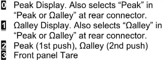
| Operation of front panel PEAK button and rear connector for Peak or Ωalley Display | Peak Display. Also selects “Peak” in “Peak or Ωalley” at connector above.Ωalley Display. Also selects “Ωalley” in “Peak or Ωalley” at connector above.Peak (1st push), Ωalley (2nd push)Front panel Tare | |
| Auto-tare | Meter comes up in normal run mode.Meter comes up in auto-tare mode | |
| Nonlinear input scaling Extended meter only. | Linear inputCustom curve linearization | |
| Filtering | Alarm filtering | Unfiltered outputFiltered output |
| Peak & Ωalley filtering | Unfiltered Peak & ΩalleyFiltered Peak & Ωalley | |
| Display filtering | Display batch average every 16 readingsDisplay filtered signal | |
| Adaptive filter threshold | Low adaptive filter threshold level*High adaptive filter threshold level | |
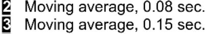
| Input signal filtering.Can be applied to display, setpoint, analog output, data output. | AutofilterBatch average, 16 readingsMoving average, 0.08 sec.Moving average, 0.15 sec.Moving average, 0.3 sec.Moving average, 0.6 sec.Moving average, 1.2 sec.Moving average, 2.4 sec.Moving average, 4.8 sec.Moving average, 9.6 sec.Unfiltered | |
| Dec. point selection | Decimal point flashes. |
 Press MenuSelect Key Press MenuSelect Key |  Press DigitSelect Key Press DigitSelect Key |   |
| Scaling method “Scale and Offset” if selected underSEtup | ||
 Scale factor Scale factor |    Select digit to flash. Select digit to flash. |  |
 Offset value Offset value |    Select digit to flash. Select digit to flash. |  |
| Scaling method “Coordinates of 2 points” if selected underSEtup | ||
 Low signal input. Low signal input. |    Select digit to flash. Select digit to flash. |  |
 Desired reading at Lo In. Desired reading at Lo In. |    Select digit to flash. Select digit to flash. |  |
 High signal input. High signal input. |    Select digit to flash. Select digit to flash. |  |
 Desired reading at Hi In. Desired reading at Hi In. |    Select digit to flash. Select digit to flash. |  |
| Scaling method “Reading coordinates of 2 points” if selected underSEtup | ||
 Low signal input. Low signal input. |    signal to the meter. signal to the meter. |   |
 High signal input. High signal input. |    Apply a high reference signal to the meter. Apply a high reference signal to the meter. |   |
 Desired reading at Lo In. Desired reading at Lo In. |    Select digit to flash. Select digit to flash. |   |
  |     |   |
Scaling method "Coordinates of 2 points" if selected under SEtuP
| Option board dependent menu items |
| ALSEt ALS34 dEU1H dEU2H dEU1b dEU2b dEU3H DEU4H DEU3b DEU4bMenu items related to alarm setup These will only appear if a relay board is detected. If so, please see Section16. |
| AnSEt An Lo An HiMenu items related to analog output setup. These will only appear if an analog output board is detected. If so, see Section 17. |
| SEr 1 SEr 2 SEr 3 SEr 4 AddrMenu items related to serial communications. These will only appear if an RS232, RS485 or USB I/O board is detected. If so, see Section 18. |
| Menu lockout items |
| Loc 1 Loc 2 Loc 3Menu items used to enable or lock out (hide) other menu items. Loc menu items may in turn be locked out by a hardware jumper. Please see Section 9. |
13. AC TRUE RMS VOLTS & AMPS INPUT
AC voltage or current measurement utilizes the True RMS signal conditioner board which uses precision circuitry to compute the root-mean-square of complex waveforms from 10 Hz to 10 kHz. Accurate measurements are obtained with spikes up to 3 times the maximum of each range. The input can be AC coupled to read only the AC component, such as ripple on a power supply, or DC coupled to read AC plus DC. The board needs to be configured via jumpers for the desired voltage or current range, and for AC or DC coupling. All signal ranges are factory calibrated with calibration factors stored in EEPROM.
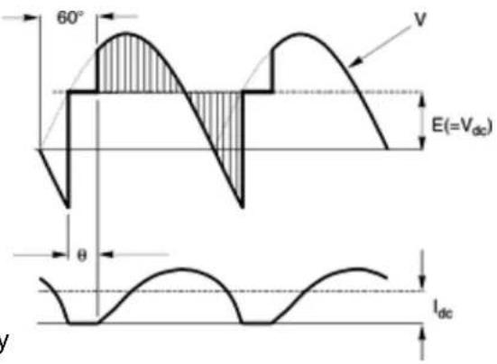
text_image
60° V E(=Vdc) θ IdcThe meter software recognizes the board and will bring up the appropriate menu items for it; however, it does not recognize the jumper settings. These need to be set manually. Please see further manual sections for setup of the following features: relay output (16), analog output (17), and communications (18).
Voltage Ranges
| Full Scale Input | Counts Jumpers | |
| 200 mΩ | 20000 | j |
| 2Ω | 20000 | c, g, h |
| 20Ω | 20000 | c, i |
| 200Ω | 20000 | c, k |
| 300Ω (UL) | 3000 | c, m |
| 600Ω (not UL) | 6000 | c, m |
Current Ranges
| Full Scale Input | Counts Jumpers | |
| 2 mA | 20000 | l, k |
| 20 mA | 20000 | b, m |
| 200 mA | 20000 | a, m |
| 5A | 5000 | c, d, e, m |
AC or DC Coupling
| Coupling Type Jumpers | |
| DC coupling for AC + DCAC coupling for AC only | fnone |
flowchart
graph TD
    A["Block m"] --> B["Processing Block"]
    C["Block i"] --> B
    D["Block h"] --> B
    E["Block g"] --> B
    F["Block f"] --> B
    G["Block e"] --> B
    H["Block d"] --> B
    I["Block c"] --> B
    J["Block b"] --> B
    K["Block a"] --> B
- Letters indicate jumper position. Jumpers are installed on pins adjacent to letters.
- Use 2.5 mm (0.1") jumpers.
- Store spare jumpers on unused jumper post.
METER SCALING
Refer to the above tables for the full scale counts (or displayed digits) produced by the available full scale input ranges with a scale factor of 1 and an offset of 0. The decimal point
can be set for direct readout in (milli)volts or (milli)amperes. Decimal point selection does not affect the counts. For example, a 20Ω input may be displayed as 20.000Ω or 20000 mΩ.
The 5A range, designed for use with a 5A current transformer (CT), is scaled to produce 5000 counts with a scale factor of 1 and an offset of 0. Use with a specific CT will require the scale factor to be set. For example, for an 800A input, 5A output CT, set a scale factor of 1.6. This is the desired 8000 count display at 5A divided by the default 5000 count display at 5A. Then set the decimal point to display to 800.0 at 5A.
All scaling methods applicable to DC, process, strain and load cell meters are available with AC RMS meters.
INTERNAL SHIELD
To reduce noise pickup inside the meter or transmitter, the RMS board is fitted with a flexible plug-on shield. If necessary, This shield may be removed for jumper setting, but must be reinstalled before closing the instrument.

natural_image
Electronic circuit board with integrated circuits and a yellow flexible cover (no visible text or symbols)SIGNAL SHIELDING

flowchart
graph LR
    A["Signal Source"] --> B["Shield around twisted pair"]
    B --> C["RMS Board"]
    C --> D["Earth Ground"]
    D --> E["Shielding for noise reduction"]
    style A fill:#f9f,stroke:#333
    style C fill:#ccf,stroke:#333
    style E fill:#cfc,stroke:#333
AC RMS measurements are susceptible to signal noise. This is especially true when the instrument has a wide bandwidth. To minimize noise pickup, the input signal wiring should utilize a shielded twisted pair, and the shield should be connected to signal low at the meter, as illustrated. If signal low is close to earth ground, such as within 2 , signal low can further be connected to earth ground at the meter, as illustrated.
KEYSTROKES FOR SETUP
If the MENU → key does not work, see Section 9 "Enabling & Locking Out Menu Items."
| MENUPress MenuSelect Key | PEAKPress DigitSelect Key | RESETPress Value SelectKey |
| InPutSelection of signal input type & range | AC UAC Ωolts | 0.2U 2.0U 20.0U 200.0U 600.0U0.2, 2, 20, 200, 660Ω FS |
| AC AAC Amps | 2.0a 20.0a 200.0a 5.0A2, 20, 200 mA, 5A FS | |
| SEtupMeter Setup | 00_00Display selection with scale factor of 1 | 0 4-1/2 digits (±20,000)1 Remote display (±99,999)2 4-1/2 digits, counts by 10 (±20,000)3 3-1/2 digits (±2,000) |
| 00_00Power line frequency | 0 Noise minimized for 60 Hz1 Noise minimized for 50 Hz | |
| 00_00Scaling method | 0 Scale and offset method1 Coordinates of 2 points method2 Reading coordinates of 2 points method | |
| 00_00Rear connector inputs 1 & 2True = logic 1 (0Ω or tied to digital ground)False = logic 0 (5Ω or open) | 0 1 = Reset, 2 = Meter Hold1 1 = Function Reset 2 = Pk or Ωalley Disp.2 1 = Meter Hold 2 = Pk or Ωalley Disp.3 1 = Meter Hold 2 = Tare4 1 = Peak or Ωalley 2 = Tare5 1 = Tare 2 = Reset6 1 = 0, 2 = 0, decimal point 1=XXXXX1 = 1, 2 = 0, decimal point 1 =XXXX.X1 = 0, 2 = 1, decimal point 1 =XXX.XX1 = 1, 2 = 1, decimal point 1 =XX.XXX7 1 = 0, 2 = 0, decimal point 2 =XXXX.X1 = 1, 2 = 0, decimal point 2 =XXX.XX1 = 0, 2 = 1, decimal point 2 = XX.XXX1 = 1, 2 = 1, decimal point 2 =XXXXX8 1 = Function Reset 2 = Display Blank9 1 = Hold 2 = Display BlankA 1 = Peak or Ωalley 2 = Display BlankB 1 = Tare 2 = Display BlankC 1 = Ωalley Display 2 = Peak DisplayD 1 = Tare 2 = Tare ResetBoth control inputs 1 & 2 set to 1 for selections 2, 4, A, C = Function Reset.Both control inputs 1 & 2 set to 1 for selections 0, 1, 3, 5, 8, 9, B, D = Meter Reset. | |
 Press Menu Select Key Press Menu Select Key |  Press Digit Select Key Press Digit Select Key |  Press Value Select Key Press Value Select Key |
 Meter Configuration Meter Configuration |   |  - - - - - - - - - - - - |
  |  - - - - | |
  | -DX8X] | |
  |  - - | |
 Filtering Filtering |   |  - - |
  |  - - | |
  |  - - | |
 Filtering for AC Filtering for AC |  - - | |
  Can be applied to display, setpoint, analog output, data output. Can be applied to display, setpoint, analog output, data output. |  - - - - - - - - - - - - - - - - - - - - | |
 Dec. point selection Dec. point selection |   |       |
| Press MenuSelect Key | Press DigitSelect Key |  Press Value SelectKey Press Value SelectKey |
| Scaling method “Scale and Offset” if selected underSEtup | ||
 Scale factor Scale factor |    Select digit to flash. Select digit to flash. | Select9thru 9for flashing first digit,0thru 9for other flashing digits. Select decimal point location when decimal point is flashing. |
| Offset value |    Select digit to flash. Select digit to flash. | Select9thru 9for flashing first digit,0thru 9for other flashing digits. Decimal point location is selected byDEC.Pt. |
| Scaling method “Coordinates of 2 points” if selected underSEtup | ||
 Low signal input. Low signal input. |    Select digit to flash. Select digit to flash. | Select9thru 9for flashing first digit,0thru 9for other flashing digits. Decimal point is set by input range chosen. |
| Desired reading at Lo In. |    Select digit to flash. Select digit to flash. | Select9thru 9for flashing first digit,0thru 9for other flashing digits. Decimal point is set byDEC.Pt. |
 High signal input. High signal input. |    Select digit to flash. Select digit to flash. | Select9thru 9for flashing first digit,0thru 9for other flashing digits. Decimal point is set by input range chosen. |
 Desired reading at Hi In. Desired reading at Hi In. |    Select digit to flash. Select digit to flash. | Select9thru 9for flashing first digit,0thru 9for other flashing digits. Decimal point is set byDEC.Pt. |
| Scaling method “Reading coordinates of 2 points” if selected underSEtup | ||
 Low signal input. Low signal input. |   3 3 signal to the meter. signal to the meter. | 0.021Press ▲ to store the low signal input in the meter. |
| High signal input. |    signal to the meter. signal to the meter. | 0.021Press ▲ to store the high signal input in the meter. |
 Desired reading at Lo In. Desired reading at Lo In. |    Select digit to flash. Select digit to flash. | 0.0000Select9thru 9for flashing first digit,0thru 9for other flashing digits. Decimal point is set byDEC.Pt. |
  |    Select digit to flash. Select digit to flash. | 6.7500Select9thru 9for flashing first digit,0thru 9for other flashing digits. Decimal point is set byDEC.Pt. |
Scaling method "Coordinates of 2 points" if selected under SEtuP
| Option board dependent menu items |
| ALSEt ALS34 dEU1H dEU2H dEU1b dEU2b dEU3H DEU4H DEU3b DEU4bMenu items related to alarm setup These will only appear if a relay board is detected. If so, please see Section16. |
| AnSEt An Lo An HiMenu items related to analog output setup. These will only appear if an analog output board is detected. If so, see Section 17. |
| SEr 1 SEr 2 SEr 3 SEr 4 AddrMenu items related to serial communications. These will only appear if an RS232, RS485 or USB I/O board is detected. If so, see Section 18. |
| Menu lockout items |
| Loc 1 Loc 2 Loc 3Menu items used to enable or lock out (hide) other menu items. Loc menu items may in turn be locked out by a hardware jumper. Please see Section 9. |
* Scaling method 2, "Reading Coordinates of 2 Points Scaling Method," will appear before all other Menu items, including InPut. Decimal point is set by dEC.Pt.
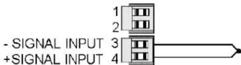
14. THERMOCOUPLE INPUT
The thermocouple signal conditioner board used for temperature measurement can be configured via jumpers for 7 thermocouple types, each in a single range: J, K, T, E, N, S, R. The meter software recognizes the board and will bring up the appropriate menu items for it; however, it does not recognize the jumper settings. Display in °C or °F and resolution of 1°, 0.1° or 0.01° are user programmable. High resolution should only be used for relative readings, not absolute readings. Although available, 0.01° resolution is not recommended for thermocouples. Offset adjustment is available for thermocouples and is normally set to 0000.0. If °C is selected, entering an offset of 0273.2 will change the display to Kelvin. If °F is selected, entering an offset of 0459.7 will change the display to Rankin.
The addition of a relay output board turns the thermocouple meter from a temperature indicator into an on/off temperature controller. Please see further manual sections for setup of the following features: relay output (Section 16), analog output (17), and communications (18).
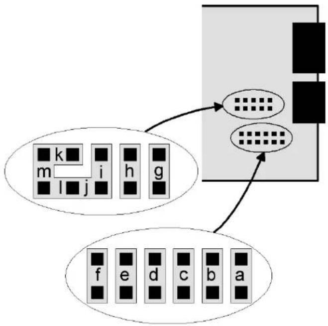
SIGNAL CONDITIONER BOARD SETUP VIA JUMPERS
| Type E4 Jumper | |
| J, K, E, NT, R, S | nonej |
| Open Indication E3 Jumper | |
| UpscaleDownscale | h i |
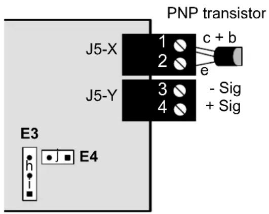
text_image
PNP transistor J5-X 1 c + b 2 e J5-Y 3 - Sig 4 + Sig E3 E4- Letters indicate jumper position.
- Jumpers are installed on pins adjacent to letters.
- Use 2.5 mm (0.1") jumpers.
- Store spare jumpers on an unused jumper post.
KEYSTROKES FOR SETUP
If the MENU → key does not work, see Section 9 "Enabling & Locking Out Menu Items."
| MENU→Press MenuSelect Key | PEAK▶Press DigitSelect Key | RESET▲Press Value SelectKey | ||
| InPutSelection of signal input type & range | tCThermocouple | J °F | J °C | Type J, °F or °C |
| K °F | K °C | Type K, °F or °C | ||
| n °F | n °C | Type N, °F or °C | ||
| E °F | E °C | Type E, °F or °C | ||
| t °F | t °C | Type T, °F or °C | ||
| S °F | S °C | Type S, °F or °C | ||
| r °F | r °C | Type R, °F or °C | ||
| SEtuPMeter Setup | 00 00Display selection. | 0 | 0.1 degree resolution | |
| 1 | Remote display (±99,999) | |||
| 2 | 0.01 degree resolution | |||
| 3 | 1 degree resolution | |||
| 00 00Power line frequency | 0 | Noise minimized for 60 Hz | ||
| 1 | Noise minimized for 50 Hz | |||
| 00 00Scaling method | 0 | Offset only for thermocouple input. | ||
| 00 00ontrol inputs 1 & 2:True = logic 1 (0Ω or tied to digital ground)False = logic 0 (5Ω or open) | 0 | 1 = Reset, 2 = Meter Hold | ||
| 1 | 1 = Function Reset, 2 = Peak or Ωalley | |||
| 2 | 1 = Hold, 2 = Peak or Ωalley Display | |||
| 3 | 1 = Hold, 2 = Tare | |||
| 4 | 1 = Peak or Ωalley Display, 2 = Tare | |||
| 5 | 1 = Tare, 2 = Reset | |||
| 6 | 1 = 0, 2 = 0, decimal point 1=XXXXX | |||
| 1 = 1, 2 = 0, decimal point 1=XXXX.X | ||||
| 1 = 0, 2 = 1, decimal point 1=XXX.XX | ||||
| 1 = 1, 2 = 1, decimal point 1=XX.XXX | ||||
| 7 | 1 = 0, 2 = 0, decimal point 2=XXXX.X | |||
| 1 = 1, 2 = 0, decimal point 2=XXX.XX | ||||
| 1 = 0, 2 = 1, decimal point 2=XX.XXX | ||||
| 1 = 1, 2 = 1, decimal point 2=X.XXX | ||||
| 8 | 1 = Function Reset 2=Display Blank | |||
| 9 | 1 = Hold 2=Display Blank | |||
| A | 1 = Peak or Ωalley 2=Display Blank | |||
| B | 1 = Tare 2=Display Blank | |||
| C | 1 = Ωalley Display 2=Peak Display | |||
| D | 1 = Tare 2=Tare Reset | |||
| Both control inputs 1 & 2 set to 1 for selections2,4,A,C=Function Reset.Both control inputs 1 & 2 set to 1 for selections0,1,3,5,8,9,E,D=Meter Reset. | ||||
 Press Menu Select Key Press Menu Select Key |  Press Digit Select Key Press Digit Select Key |  Press Value Select Key Press Value Select Key | ||
 Meter Configuration Meter Configuration |  | No used. | ||
  |  | |||
 Filtering Filtering |  Alarm filtering Alarm filtering |  | ||
 Peak & Ωalley filtering Peak & Ωalley filtering |  | |||
 Display filtering Display filtering |  | |||
 Adaptive filter threshold Adaptive filter threshold |  | |||
 Input signal filtering. Can be applied to display, setpoint, analog output, data output. Input signal filtering. Can be applied to display, setpoint, analog output, data output. | 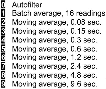 Unfiltered Unfiltered | |||
| OFFst Offset value |  0.0000 0.0000 0.0000 0.0000  0.0000 0.0000  |  | ||
| Option board dependent menu items | ||||
          Menu items related to alarm setup if a relay board is detected. Please see Section16. Menu items related to alarm setup if a relay board is detected. Please see Section16. | ||||
               7. 7. | ||||
         [3KYS] [3KYS]     Section 18. Section 18. | ||||
     | ||||
        ( [4YXX] [KZSZ] [WYS6] ( [4YXX] [KZSZ] [WYS6]   . . | ||||
15. RTD & RESISTANCE INPUT
RTD and resistance measurement can be configured via jumpers for four RTD types (DIN platinum, ANSI 100Ω platinum, 120Ω nickel, 10Ω copper) or five resistance ranges (from 20.000Ω to 200.00 kΩ). All ranges are factory calibrated with calibration factors stored in EEPROM on the signal conditioner board. The meter software recognizes the board and will bring up the appropriate menu items for it; however, it does not recognize the jumper settings. With RTDs, display in °C or °F and resolution of 1°, 0.1° or 0.01° are user programmable.
Please see further manual sections for setup of the following features: relay output (Section 16), analog output (17), and communications (18).
SIGNAL CONDITIONER BOARD SETUP VIA JUMPERS
| RTD Type or Ohms E1 | Jumper |
| Pt100, Ni120 | a |
| Cu10, 20.000 Ω | b |
| 200.00 Ω | c |
| 2000.0 Ω | d |
| 20000 Ω or 20.000 kΩ | e |
| 200.00 kΩ | f |
| Connection E2 Jumper | |
| 2 or 4 wire | none |
| 3 wire | g |
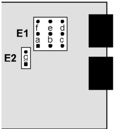
text_image
E1 f e d a b c E2 g- Program decimal point selection under dEc.Pt menu item.
- Letters indicate jumper position. Jumpers are installed on pins adjacent to letters.
- Store spare jumpers on an unused jumper post.
SCALE & OFFSET SETUP
Scale is normally set to 1.0000. Scale can be used as an RTD correction when actual resistance is other than nominal, as stated on the RTD calibration sheet. For a Pt100 RTD, divide 100 by the stated resistance at 0^ C. For example, for a 99.04 ohm RTD, scale should be set to 100 / 99.04 = 1.0097.
SIGNAL SHIELDING

text_image
Resistance Shield around twisted pair Sig High Sig Low Ohms BoardShielding for noise reduction
200 kΩ ranges and above measurements are susceptible to signal noise. To minimize noise pickup, the input signal wiring should utilize a shielded twisted pair and the shield should be connected to signal low and earth ground at the meter, as illustrated. Use 2-wire hookup
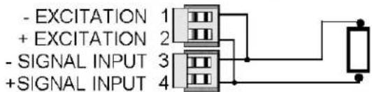
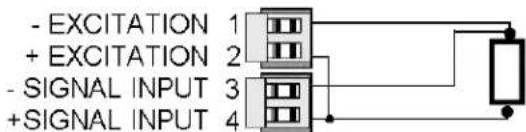
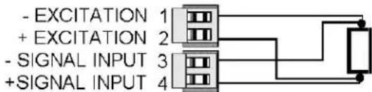
RTD & RESISTANCE CONNECTION
With the appropriate jumper settings, RTD and resistance measurements allow 2, 3 or 4-wire RTD hookup to the J5 connector, as illustrated. The meter applies a fixed excitation current.
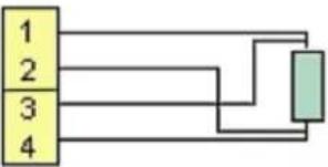
In 4-wire hookup, lead resistance is not a factor, since different pairs of wires are used for excitation and sensing.
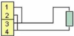
In 3-wire hookup, the meter automatically compensates for lead resistance by measuring the voltage drop in one current-carrying lead and assuming that the voltage drop in the other current-carrying lead is the same.
In 2-wire hookup, the meter senses the voltage drop across the load and both lead wires. The effect of the lead wires can be measured and subtracted by shorting out the load during meter setup. The short should be as close as possible to the load. Ambient temperature changes will still cause some error in the readings -- the higher the lead resistance, the greater the error.
4-wire RTD or resistance
-Excitation
+Excitation
-Signal input
+Signal input
flowchart
graph TD
    A["1"] --> B["2"]
    B --> C["3"]
    C --> D["4"]
    D --> E["Output"]
3-wire RTD or resistance
-Excitation
+Excitation
-Signal input
+Signal input

flowchart
graph TD
    A["1"] --> B["2"]
    B --> C["3"]
    C --> D["4"]
    D --> E["Green Box"]
2-wire RTD or resistance
-Excitation
+Excitation
-Signal input
+Signal input
flowchart
graph TD
    A["1"] --> B["2"]
    B --> C["3"]
    C --> D["4"]
    D --> E["Output"]
To eliminate lead wire resistance, follow this procedure:
- Set the InPut menu item and jumpers for the desired range
- Set COnFG to 00011.
- Short the two leads at the sensor end.
- When the display has settled, push the ▶ key. The meter will then store a value proportional to lead resistance, automatically change COnFG to 00010, and then reset. The same result is obtained by grounding a Control Input that has been selected for Peak or Ωalley (SEtuP 00_0Y, where Y = 1, 2, 4, A, C).
- Remove the short and connect the sensor. The meter now processes the sensor resistance only.
If the range and associated jumpers are subsequently changed, the above procedure must be repeated. This procedure is also available through Instrument Setup software, Revision 2.7.0 or later.
KEYSTROKES FOR SETUP
If the MENU → key does not work, see Section 9 "Enabling & Locking Out Menu Items."
| MENU→Press MenuSelect Key | PEAK▶Press DigitSelect Key | RESET▲Press Value SelectKey |
| InPutSelection of signal input type & range | rtdRTD | d °F Pt100 RTD, DIN alpha .00385, °Fd °C Pt100 RTD, DIN alpha .00385, °CA°F Pt100 RTD, ANSI alpha .003902, °FA°C Pt100 RTD, ANSI alpha .003902, °Cni°F Ni120 RTD, alpha .00672, °Fn°C Ni120 RTD, alpha .00672, °CCu°F Cu10 RTD, alpha .00427, °FCu°C Cu10 RTD, alpha .00427, °C |
| OHnnSOhmmeterSet decimal pointunder dEc.Pt | 20 0 to 20.000 ohms200 0 to 200.00 ohms2000 0 to 2000.0 ohms20000 0 to 20000 ohms200.00 0 to 200.00 kohm | |
| SEtuPMeter Setup | 00 00Display selection with scale factor of 1. | 0 0.1° RTD or 4-1/2 digits for ohms1 5-digit remote display (±99,999)2 0.01° RTD, 4-1/2 digit ohms count by 103 1° RTD or 3-1/2 digits for ohms |
| 00 00Power line frequency | 0 Noise minimized for 60 Hz1 Noise minimized for 50 Hz | |
| 00 00Scaling method | 0 Scale and offset method (RTD & ohms)1 Coordinates of 2 points (ohms)2 Reading coordinates of 2 points (ohms) | |
| 00 00Control inputs 1 & 2:True = logic 1 (0Ω or tied to digital ground)False = logic 0 (5Ω or open) | 0 1 = Reset, 2 = Meter Hold1 1 = Function Reset, 2 = Peak or Ωalley2 1 = Hold, 2 = Peak or Ωalley Display3 1 = Hold, 2 = Tare4 1 = Peak or Ωalley Display, 2 = Tare5 1 = Tare, 2 = Reset6 1 = 0, 2 = 0, decimal point 1=XXXXX1 = 1, 2 = 0, decimal point 1 =XXXX.X1 = 0, 2 = 1, decimal point 1 =XXX.XX1 = 1, 2 = 1, decimal point 1 =XX.XXX7 1 = 0, 2 = 0, decimal point 2 =XXXX.X1 = 1, 2 = 0, decimal point 2 =XXX.XX1 = 0, 2 = 1, decimal point 2 =XX.XXX1 = 1, 2 = 1, decimal point 2 =X.XXXX | |
| SEtupMeter Setup(continued) | 00 00Control inputs 1 & 2(continued) | 8 1 = Function Reset 2 = Display Blank9 1 = Hold 2 = Display BlankA 1 = Peak or Ωalley 2 = Display BlankB 1 = Tare 2 = Display BlankC 1 = Ωalley Display 2 = Peak DisplayD 1 = Tare 2 = Tare ResetBoth control inputs 1 & 2 set to 1 for selections 2, 4, A, C = Function Reset.Both control inputs 1 & 2 set to 1 for selections 0, 1, 3, 5, 8, 9, E, D = Meter Reset. |
| ConFGMeter Configuration | 00000Operation as a rate of change meter.Extended meter only. | 0 Not rate of change 3 Rate x 101 Rate x 0.1 5 Rate x 10002 Rate x 1 6 Rate x 10000 |
| 00000Operation of front panel PEAK button and rear connector for Peak or Ωalley Display | 0 Peak Display. Also selects “Peak” in “Peak or Ωalley” at connector above.1 Ωalley Display. Also selects “Ωalley” in “Peak or Ωalley” at connector above.2 Peak (1st push), Ωalley (2nd push)3 Front panel Tare | |
| 00000Auto-tare selection | 0 No auto-tare1 Auto-tare | |
| 00000RTD or Ohms wiring | RTD Ohms00 3 or 4 wire 3 or 4 wire01 Not allowed Custom curve10 2-wire read 2-wire read11 2-wire short 2-wire short | |
| FiLtrFiltering | 00000Alarm filtering | 0 Unfiltered output1 Filtered output |
| 00000Peak & Ωalley filtering | 0 Unfiltered Peak & Ωalley1 Filtered Peak & Ωalley | |
| 00000Display filtering | 0 Display batch average every 16 readings1 Display filtered signal | |
| 00000Adaptive filter threshold | 0 Low adaptive filter threshold level1 High adaptive filter threshold level | |
| MENUPress MenuSelect Key |  Press DigitSelect Key Press DigitSelect Key |  Press Value SelectKey Press Value SelectKey |
| FiLtrFiltering(continued) |   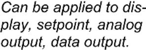   | AutofilterBatch average, 16 readingsMoving average, 0.08 sec.Moving average, 0.15 sec.Moving average, 0.3 sec.Moving average, 0.6 sec.Moving average, 1.2 sec.Moving average, 2.4 sec.Moving average, 4.8 sec.Moving average, 9.6 sec.AUnfiltered |
| dEc.PtDecimal point selection | ||
| SCALEScale factor | elect thru 9 for flashing first digit, thru 9for other flashing digits. Select decimal point location when decimal point is flashing. | |
| OFFstOffset value | elect thru 9 for flashing first digit, thru 9for other flashing digits. Use offset for display in Rankine or Kelvin. Decimal point location is selected by dEC.Pt. | |
| Option board dependenu items | ||
| ALSEtALS34 dEU1h [REDA] 2H dEU1b dEU2b [REDA] DEU4H DEU3b DEU4bMenu items related to setup These will only appear if a relay board is detected. If so, please see Section16. | ||
| AnSEtAn Lo An Hi [REDA]Menu items related to output setup These will only appear if an analog output board is detected. If so, Section 17. | ||
| SEr 1 SEr 2 SEr 3 S [REDA] AddrMenu items related to communications. These will only appear if an RS232, RS485, or USB I/O board is de [REDA]. If so, see Section 18. | ||
| Menu lockout items [REDA] | ||
| Loc 1 Loc 2 Loc 3 [REDA]Menu items used to enter lock out (hide) other menu items. Loc menu items may in turn be locked out by a har jumper. Please see Section 9. | ||
16. DUAL OR QUAD RELAY OUTPUT OPTION
An optional relay board may be installed in the meter main board at plug position P2, adjacent to the power supply board. Four board versions are available: 2 or 4 relays, mechanical or solid state. Once installed, the relay board is recognized by the meter software or PC-based Instrument Setup software, which will bring up the appropriate menu items for the type of board. These menu items will not be brought up if no relay board is detected. Menu selections for relays 3 and 4 will not be brought up if the dual relay board is detected. All

text_image
-9.9999 Alarm 1 1 2 3 4 Alarm 4 MENU PEAK RESET ALARMSrelay boards offer a choice of operating modes: normally off or on, latched or non-latched, hysteresis band, deviation band, alarm based on the filtered or unfiltered signal, and selectable number of readings in alarm zone to cause an alarm.
KEYSTROKES FOR VIEWING & CHANGING SETPOINTS
The (Alarms) key can be used to step through and view setpoints while the meter continues to make conversions and performs setpoint control. If the Peak key is pressed while a setpoint is displayed, conversion stops and the setpoint can be changed. After pressing , you have 30 seconds, or the meter reverts to the normal display. To view setpoints, menu item Loc3, digit 2, must have been set to 0. To change setpoints, menu item Loc2, digit 2, must have been set to 0.
 Press Alarms Key Press Alarms Key |  Press Digit Select Key Press Digit Select Key |  Press Value Select Key Press Value Select Key |
300.24  ←(Alarms) to display Alarm 1 setpoint. ←(Alarms) to display Alarm 1 setpoint. | 200.00 Current setpoint 1 value blinks, and Alarm 1 LED indicator lights. Press ► to select a digit, which will blink. | 295.00 To change setpoint 1 value, press ▲to change selected blinking digits. |
 Press←(Alarms) to display Alarm 2 setpoint. Press←(Alarms) to display Alarm 2 setpoint. | 395.00 Current setpoint 2 value blinks, and Alarm 2 LED indicator lights. Press ► to select a digit, which will blink. | 305.00 To change setpoint 2 value, press ▲to change selected blinking digits. |
 Press←(Alarms) to display Alarm 3 setpoint. Press←(Alarms) to display Alarm 3 setpoint. | 395.00 Current setpoint 3 value blinks, and Alarm 3 LED indicator lights. Press ► to select a digit, which will blink. | 305.00 To change setpoint 3 value, press ▲to change selected blinking digits. |
 Press←(Alarms) to display Alarm 4 setpoint. Press←(Alarms) to display Alarm 4 setpoint. | 395.00 Current setpoint 4 value blinks, and Alarm 4 LED indicator lights. Press ► to select a digit, which will blink. | 305.00 To change setpoint 4 value, press ▲to change selected blinking digits. |
 Press←(Alarms) again. Meter will reset and display current reading. Press←(Alarms) again. Meter will reset and display current reading. | ||
KEYSTROKES FOR SETPOINT SETUP
If the MENU key does not work, see Section 9 "Enabling & Locking Out Menu Items."
 Press Menu Select Key Press Menu Select Key |  Press Digit Select Key Press Digit Select Key |  Press Value Select Key Press Value Select Key |
 Alarm Setup for relays 1 & 2 if detected.Press → until ALSEt is displayed. Alarm Setup for relays 1 & 2 if detected.Press → until ALSEt is displayed. |  Relay state when alarm is active. Relay state when alarm is active. | Relay 1 on Relay 2 onRelay 1 off Relay 2 onRelay 1 on Relay 2 offRelay 1 off Relay 2 off |
| Alarm latching or non-latching (auto reset). | Alarm 1 auto reset Alarm 2 auto resetAlarm 1 latching Alarm 2 auto resetAlarm 1 auto reset Alarm 2 latchingAlarm 1 latching Alarm 2 latching | |
| Alarm operates at and above setpoint (active high) or at and below setpoint (active low). | AL1 active high AL2 active highAL1 active low AL2 active highAL1 disabled AL2 active highAL1 active high AL2 active lowAL1 active low AL2 active lowAL1 disabled AL2 active lowAL1 active high AL2 disabledAL1 active low AL2 disabledAL1 disabled AL2 disabled | |
| Hysteresis mode or band deviation mode | AL1 band deviation AL2 band deviationAL1 split hysteresis AL2 band deviationAL1 band deviation AL2 split hysteresisAL1 split hysteresis AL2 split hysteresisNo deviation or hysteresis in menu.AL1 span hysteresis AL2 band deviationAL1 span hysteresis AL2 split hysteresisAL1 span hysteresis AL2 span hysteresis | |
| Number of consecutive readings in alarm zone to cause an alarm. | After 1 reading After 16 readingsAfter 2 readings After 32 readingsAfter 4 readings After 64 readingsAfter 8 readings After 128 reading | |
| ALS34Alarm Setup for relays 3 & 4 if detected. | Relay state when alarm is active. | Relay 3 on Relay 4 onRelay 3 off Relay 4 onRelay 3 on Relay 4 offRelay 3 off Relay 4 off |
| Alarm latching or non-latching (auto reset). | Alarm 3 auto reset Alarm 4 auto resetAlarm 3 latching Alarm 4 auto resetAlarm 3 auto reset Alarm 4 latchingAlarm 3 latching Alarm 4 latching |
The Ground Truth image displays a single, continuous horizontal line, which is a stylistic or background element (like a ruled paper line). According to Rule 2, such lines must be ignored by the OCR result. The provided OCR content is "____", which consists of underscores. Underscores are not equivalent to a solid line in this context; they represent a distinct character often used as placeholders. Since the OCR output incorrectly rendered a stylistic line as underscores (it’s a textual placeholder), this violates the rule that stylistic lines must be ignored. Therefore, the OCR result is inconsistent with the Ground Truth.
| MENU→Press MenuSelect Key | PEAK▶Press DigitSelect Key | RESET▲Press Value SelectKey |
| ALS34Alarm Setup for relays 3 & 4 (continued) | 00000Alarm operates at and above setpoint (active high) or at and below setpoint (active low). | 0 AL3 active high AL4 active high1 AL3 active low AL4 active high2 AL3 disabled AL4 active high3 AL3 active high AL4 active low4 AL3 active low AL4 active low5 AL3 disabled AL4 active low6 AL3 active high AL4 disabled7 AL3 active low AL4 disabled8 AL3 disabled AL4 disabled |
| 00000Hysteresis mode or band deviation mode (see Glossary) | 0 AL3 band deviation AL4 band deviation1 AL3 hysteresis AL4 band deviation2 AL3 band deviation AL4 hysteresis3 AL3 hysteresis AL4 hysteresis | |
| 00000Number of consecutive readings in alarm zone to cause an alarm. | 0 After 1 reading 4 After 16 readings1 After 2 readings 5 After 32 readings2 After 4 readings 6 After 64 readings3 After 8 readings 7 After 128 reading | |
| dEU1HAlarm 1 hysteresis | 0.0000 0.0000 0.00000.0000 0.0000Select digit to flash. | Select -9 thru 9 for flashing first digit, 0 thru 9 for other flashing digits. Alarms will activate above the setpoint by the value entered and deactivate below the setpoint by the value entered. |
| DEU2HAlarm 2 hysteresis | ||
| DEU1bAlarm 1 band deviation | 0.0000 0.0000 0.00000.0000 0.0000Select digit to flash. | Select -9 thru 9 for flashing first digit, 0 thru 9 for other flashing digits. Alarms will activate above and below the setpoint by the value entered and will deactivate in the middle of the band. |
| DEU2bAlarm 2 band deviation | ||
| dEU3HAlarm 3 hysteresis | 0.0000 0.0000 0.00000.0000 0.0000Select digit to flash. | Select -9 thru 9 for flashing first digit, 0 thru 9 for other flashing digits. Alarms will activate above the setpoint by the value entered and deactivate below the setpoint by the value entered. |
| DEU4HAlarm 4 hysteresis | ||
| DEU3bAlarm 3 band deviation | 0.0000 0.0000 0.00000.0000 0.0000Select digit to flash. | Select -9 thru 9 for flashing first digit, 0 thru 9 for other flashing digits. Alarms will activate above and below the setpoint by the value entered and will deactivate in the middle of the band. |
| DEU4bAlarm 4 band deviation |
17. ANALOG OUTPUT OPTION
An optional analog board may be installed in the meter at rear panel jack position J4, adjacent to the signal conditioner board. Once installed, this board is recognized by the meter, which will bring up the appropriate menu items for it. These will not be brought up if an analog output board is not installed.
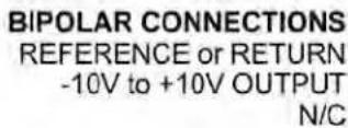
The analog output can be a 0-20 mA, 4-20 mA or 0-10Ω unipolar signal with respect to isolated ground, or a bipolar -10Ω to +10Ω voltage signal with respect to a reference return line. Unipolar or bipolar operation is selected by a jumper. A unipolar current or voltage output is selected at the connector. Unipolar 4-20 mA or 0-20 mA current is selected in software.
text_image
a b
text_image
UNIPOLAR CONNECTIONS 4-20 mA or 0-20 mA OUTPUT 0-10V OUTPUT ISOLATED GROUND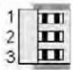
Unipolar current of voltage: Jumper a Bipolar -10 to +10 voltage: Jumper b
The low analog output (0 mA, 4 mA, 0Ω, or -10Ω) may be set to correspond to any low displayed reading An Lo. The high analog output (20 mA, 0Ω or 10Ω) may be set to correspond to any high displayed reading An Hi. The meter will then apply a straight line fit between these two end points to provide an analog output scaled to the meter reading.
KEYSTROKES FOR SETUP
If the MENU ▪ key does not work, see Section 9 "Enabling & Locking Out Menu Items."
 Press MenuSelect Key Press MenuSelect Key |  Press Digit SelectKey Press Digit SelectKey |  Press Value SelectKey Press Value SelectKey |
 Analog Output Setup. Analog Output Setup. until AnSEtis displayed (requires until AnSEtis displayed (requires output board). output board). |  Analog output signal Analog output signal on. on. | 0 0-20 mA current output1 0-10Ω voltage output2 4-20 mA current output3 -10 to +10Ω voltage output |
 Analog output filtering. Analog output filtering. | 0 Analog output unfiltered1 Analog output filtered | |
 Low displayed valuefor 0 mA, 4 mA, 0Ω, or-10Ω output Low displayed valuefor 0 mA, 4 mA, 0Ω, or-10Ω output |  0.0000 0.0000   0.0000 0.0000  Select digit to flash. Select digit to flash. | Select -9 thru 9 for flashing first digit, 0 thru 9 for other flashing digits. Decimal point location is fixed by dEC.Pt selection. |
| An HiHigh displayed valuefor 20 mA or 10Ω output |  0.0000 0.0000   0.0000 0.0000  Select digit to flash. Select digit to flash. | Select -9 thru 9 for flashing first digit, 0 thru 9 for other flashing digits. Decimal point location is fixed by dEC.Pt selection. |
18. SERIAL COMMUNICATION OPTIONS
A serial communications board may be connected to the meter main board at plug position P13 (middle position). Available boards are RS232, RS485 (with dual RJ11 connectors), RS485 Modbus (with dual RJ45 connectors), USB, USB-to-RS485 converter. The dual connectors of RS485 boards are wired in parallel to allow daisy chaining of addressable meters without use of a hub. Three serial communication protocols are selectable for all serial boards: Custom ASCII, Modbus RTU, and Modbus ASCII.
A USB-to-RS485 converter board allows a meter to be interfaced to a computer and be the device server for a network of up to 31 other meters on an RS485 bus, while itself retaining all capabilities of a meter. The remote meters need to be equipped with our RS485 digital interface board with dual 6-pin RJ11 jacks, not our RS485 digital interface with dual 8-pin RJ45 jacks. The dual 6-pin RJ11 jacks on the RS485 board are wired in parallel to allow multiple meters to be daisy-chained using readily-available 6-wire data cables with no need for hand-wiring or an RS485 hub. The outer two wires are used for ground.
Use 6-wire, straight-through data cables, not 4-wire telephone cables or crossover cables, all the way from the device server to the last device on the RS485 bus. Connect ATX to ATX, BTX to BTX, etc., with no crossover as you go from device to device.
To connect a meter with a USB board to a computer, use a USB cable with Type A and Type B connectors. The computer will display “Found new Hardware” followed by “Welcome to the Found new Hardware Wizard.” Follow the instructions for software installation from a CD. When the installation is complete, use Device Manager to determine the com port. To get to Device Manger, go to the Windows Control Panel, click on System, click on the Hardware tab, then click on Device Manager. Go down the device list and click on Ports (COM & LPT) and USB serial port (com #). Note the com port # for use with communications to your meter, then exit Control Panel. If you later need to change the Com port, right-click on USB serial port (com #), then on Properties, Port settings, and Advanced. Change port to the desired number, click OK, then exit Control Panel.
BOARD SETUP VIA JUMPERS
USB Board
No jumpers required.

text_image
USB USB| RS232 Boarde - Normal operation.f - Slave display to RS232 from another meter.g - Pull-up resistor on RTS line.Note: Board is shipped with jumpers e and g installed |  |
| RS485 Board, Full Duplex Operationb & d - Installed on last meter in long cable run.RS485 Board, Half Duplex Operationa & c - Installed for half duplex operation.d - Installed on last meter in line with long cable runs.Note: Board is shipped with no jumpers installed. | 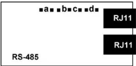 |
| RS485-Modbus Board, Full Duplex Operationb & e - Bias jumpers should be installed on 1 board.a & d - Installed on last meter in long cable run.RS485-Modbus Board, Half Duplex Operationb & e - bias jumpers installed on 1 board.c & f - installed for half duplex operation.a - installed on last meter in line with long cable runs.Note: Board is shipped with no jumpers installed. |  |
| USB-to-RS485 Converter BoardFull Duplex OperationNo jumpers for short cable runs.Add b & d for long cable runs.Half Duplex Operationa & c - Installed for half duplex operation.d - Installed on last meter in line with long cable runs. |  |
SERIAL CONNECTION EXAMPLES

text_image
EthernetEthernet, USB or RS232 cable

Meter with Ethernet, USB, or RS232 serial interface board
Host computer

text_image
EthernetHost computer
Ethernet or USB cable
Meter with RS485 server board, Ethernet-to-serial or USB-to-serial
RS485 hub via RJ11 connectors and 6-wire data cables
RS485
RS485
Meters with RS485 I/O boards, each with two RJ11 connectors
Ethernet cable
Router or switch
Ethernet cable
RS485
RJ11


RJ11

RJ11

RJ11


Meter with Ethernet I/O board with RJ45.
Meter with Ethernet-to-serial server board.
RJ45 to Ethernet.
RJ11 to RS485 bus.
Meters with RS485 I/O boards, each with two RJ11's for daisy-chained RS485

natural_image
Illustration of a laptop with open screen and keyboard (no visible text or symbols)Host computer

flowchart
graph TD
    A["Router"] --> B["Internet & modems"]
    B --> C["Router"]
    C --> D["Ethernet-to-serial server"]
    D --> E["RS485 via 6-wire data cables"]
    D --> F["RS485 via discrete wires"]
    D --> G["Transmitters"]
    H["Host computer"] --> I["Computer"]
    style A fill:#f9f,stroke:#333
    style H fill:#ccf,stroke:#333
    style B fill:#cfc,stroke:#333
    style C fill:#fcc,stroke:#333
    style D fill:#cff,stroke:#333
    style E fill:#ffc,stroke:#333
    style F fill:#ffc,stroke:#333
    style G fill:#ffc,stroke:#333
KEYSTROKES FOR SETUP
If the MENU Key does not work, see Section 9 "Enabling & Locking Out Menu Items."
| MENU→Press Menu Select Key | PEAK▶Press Digit Select Key | RESET△Press Value Select Key |
| SEr 1Fixed Parameters:No parity8 data bits1 stop bit | 000Output filtering | 0 Send unfiltered signal1 Send filtered signal |
| 000Baud rate | 0 300 baud1 600 baud2 1200 baud3 2400 baud4 4800 baud5 9600 baud6 19200 baud | |
| 000Output update rate | 60 Hz 50 Hz0 Line frequency Line frequency1 0.28 sec 0.34 sec2 0.57 sec 0.68 sec3 1.1 sec 1.4 sec4 2.3 sec 2.7 sec5 4.5 sec 5.4 sec6 9.1 sec 10.9 sec7 18.1 sec 21.8 sec8 36.6 sec 43.5 sec9 72.5 sec 97 sec | |
| Press Menu Select Key | Pi sK(57CT) [0X5K] [DAWD] [TST8] | [37H1 ]Press Value Select Key |
 Serial Setup 2 Serial Setup 2 |  Line fee [45TB] [7RTZ] [ATTZA] Line fee [45TB] [7RTZ] [ATTZA] | 0 No line feed after carriage return1 Line feed after carriage return |
 Alarm d (CH2A) w readings [HISTO] Alarm d (CH2A) w readings [HISTO] | 0 No alarm data1 Alarm data with reading | |
 Control (2ACT) da output Control (2ACT) da output  | 0 Continuous data output1 Data output on ASCII command only | |
 Meter address with Cust ASCII protoc [36W3] Meter address with Cust ASCII protoc [36W3] | Select 1 thru F for addresses 1 thru 15. Select 0 thru F (with decimal point) for addresses 16 thru 31. | |
| SEr 3Serial Setup 3 |  [BDC7] [7KIO] [BDC7] [7KIO]  Half or full duplex Half or full duplex | 0 Full duplex1 Half duplex |
[T6ZO]  [7TT] Special start stop char [7TT] Special start stop char | 0 Standard continuous mode1 Special start & stop characters | |
[42TO] [C4Z3] [4AYI] [1YYI]RTS moue [4AKH] [VDCZ]  [ABAH] [HS3H] Termination characters [ABAH] [HS3H] Termination characters | 0 Normal RTS1 Single transmission0 Only at end of all items1 At end of each item | |
| SEr 3Serial Setup 3 (continued) | [YCBY]Data send continuous mode [5HYT] [X0YD] [AYKS] [BYAX] [X345]   | 0 Reading1 Peak2 Ωalley3 Reading + peak4 Reading + valley5 Reading + peak + valley |
| SEr 4Serial Setup 4. | [CDKK] [DVD3] [ASCE] Modbus ASCU gap timed  [XHS3] [AZB3] [X4XX] [1YXX] [16OTY] [24WT] [XHS3] [AZB3] [X4XX] [1YXX] [16OTY] [24WT]    [44SS1] [7520] [44SS1] [7520] | 0 1 sec1 3 sec2 5 sec3 10 sec |
| [000] [0270] [870W] [C00T] | 0 Custom ASCII1 Modbus RTU2 Modbus ASCII | |
[06DH]  [HS2T] Parity [22AD] [82HS] [3XXX] [HS2T] Parity [22AD] [82HS] [3XXX]   [0KWW] [0KWW] | 0 None, 2 or more stop bits1 Odd, 1 or more stop bits2 Even, 1 or more stop bits | |
| AddrModbus Address. Appears only if the Modbus protocol is selected. | [000] [000] [000] [000] [000] [000] [000] [000] [000] [000] [000] [000] [000] [000] [000] [000] [000] [000] [000] [000] [000] | 247Select 0 through 9 for flashing digit. Address range is 1 to 247. |


19. EXCITATION OUTPUT & POWER SUPPLY
Three isolated transducer excitation output levels are available from the power supply board. These are selectable via jumpers b, c, d, e, f in the upper right of the board, as illustrated. In addition, the board provides three jumper positions for special features. The same jumper locations apply to the universal power supply (85-264 _ac ) and to the low voltage power supply (12-32 _ac or 10-48 _dc ).

Jumper a - Front panel menu lockout, locked when installed. (See Section 9)
Jumper g - Provides +5Ω power output at P1-4 when installed.
Jumper h - Connects "Control Input 2" to P1-4 when installed.
20. INSTRUMENT SETUP VIA PC
Instrument Setup software is a PC program which is much easier to learn than front panel programming. It is of benefit whether or not the meter is connected to a PC. With the meter connected to a PC, it allows uploading, editing and downloading of setup data, execution of commands under computer control, listing, plotting and graphing of data, and computer prompted calibration. With the meter unconnected to a PC, it provides quick selection of jumper locations and a printable display of menu selections for front panel setup.
SOFTWARE INSTALLATION
Download /S2*.exe onto your PC from the web or the distribution CD. Double-click on the downloaded file to unzip it into a special directory, such as c:\temp. Within that directory, double-click on setup.exe, which will install the software on your PC.
PREREQUISITES FOR CONNECTED USE
1) PC with an available RS232 or USB port.
2) Meter to be set up.
3) RS232 or USB board in the meter. This board can be removed following meter setup.
4) RJ11-to-DB9 cable from the meter to a PC RS232 com port, or a USB cable to a PC USB port (see Section 1, Ordering Guide).
5) Instrument Setup software.

text_image
5 2 5 1 9 6RJ11-to-DB9 RS-232 cable
ESTABLISHING COMMUNICATIONS
Connect the meter and PC. Apply power to the meter. Be sure that the meter is in Run Mode, not Setup Mode. To start the software from Windows, click on Start => Programs => IS2 => IS2. Click on RS232 => Establish. The program will temporarily set the selected Com port to the required baud rate, parity, data bits and stop bit. Once communications have been established, click on Main Menu. The software will sense the type of meter and installed boards, but it cannot sense jumpers positions nor set jumpers for you. If the computer is not connected to a meter, select DPM and Series 2.

text_image
Establish Communications@PM Corn Ports ● Com 1 ○ Com 2 ○ Com 3 ○ Com 4 ○ Com 5 ○ Com 6 ○ Com 7 ○ Com 8 ○ Com 9 Band Rate ○ 300 ○ 600 ○ 1200 ○ 2400 ○ 48009600
○ 19200 Protocol ● Custom ASCII ○ Modbus RTU ○ Modbus ASCII Help Parity ● None Establish Main Menu Back Quit Other Corn Port Wait while attempting to establish communications Motor Type: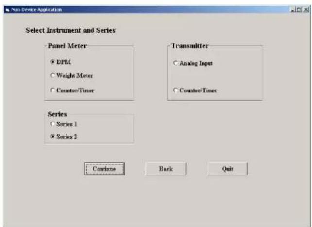
text_image
Non-Device Application Select Instrument and Series Panel Meter • DPM • Weight Meter • Counter/Timer Transmitter • Analog Input • Counter/Timer Series • Series 1 • Series 2 Continue Back Quit
text_image
Setup Input+Display Scaling Filter Relay Alarms Communication Analog Out Lockouts BASIC Option Sig Cord Option Relay Option Comm Option Analog Option EXTENDED Boards DC Relay Board RS232 Board None Signal Input Mode Range Custom Curve Rate 50/60 Hz Line Freq DC V 0.2V Disabled Disabled 60 Hz Display Resolution Display Filter Decimal Point Peak Button Action Auto Tape 4.5 Digits Filtered dddd. Control Inputs Control Input A....Control Input B....Both Ctrl A,B... Meter Reset Meter Hold Cald Reset Main Menu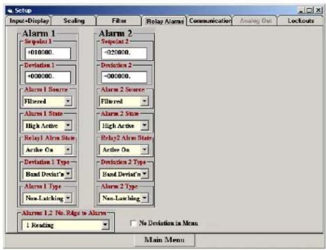
text_image
Setup Input+Display Scaling Filter Relay Alama Communication Analog Out Lockouts Alarm 1 Sequent 1 +010000. Deviation 1 +000000. Alarm 1 Source Filtered Alarm 1 State High Active Relay1 Alarm State Active On Deviation 1 Type Band Deviat'n Alarm 1 Type Non-Latching Alarm 2 Sequent 2 -020000. Deviation 2 -000000. Alarm 2 Source Filtered Alarm 2 State High Active Relay2 Alarm State Active On Deviation 2 Type Band Deviat'n Alarm 2 Type Non-Latching Alarms 1.2 No. Ridge to Alarm 1 Reading No Deviation in Menu Main MenuSETUP OF CONNECTED METER
A setup file can be retrieved from the meter (DPM => Get Setup), be edited (View => Setup), be saved to disk (File => Save Setup), be retrieved from disk (File => Open Setup), and be downloaded into one or multiple meters (DPM => Put Setup). Downloading of setup files from a PC can be a major time saving when multiple meters have to be set up in the same way.
You will find that Instrument Setup software is very user friendly, with separate tab-selectable windows for Input+Display, Scaling, Filter, Relay Alarms, Communications, Analog Out, and Lockouts. If the required hardware, such as the analog output board, is not sensed, the corresponding tab will be grayed out.
ADDITIONAL FEATURES
- The Commands pull-down menu allows you to execute certain meter functions by using your computer mouse. You can reset individual meter functions, display current or peak readings, and enter numbers to be displayed remotely by the DPM. The first position of a transmitted number must be a blank, + sign or - sign. Five digits and a decimal point must be transmitted. Leading 0's serve as blanks. The Commands pull-down menu will be grayed out unless a Get Setup has been executed.

line
| Time | Value | |------|-------| | 0 | 2825 | | 1 | 2820 | | 2 | 2815 | | 3 | 2810 | | 4 | 2840 | | 5 | 2860 | | 6 | 2780 | | 7 | 2750 | | 8 | 2830 | | 9 | 2845 | | 10 | 2840 |Plot
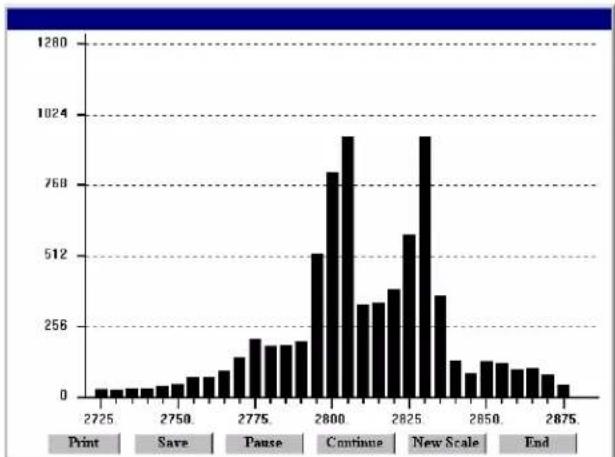
bar
| Time | Frequency | |---|---| | 2725 | 3 | | 2730 | 4 | | 2735 | 4 | | 2740 | 4 | | 2745 | 5 | | 2750 | 6 | | 2755 | 8 | | 2760 | 10 | | 2765 | 12 | | 2770 | 16 | | 2775 | 20 | | 2780 | 16 | | 2785 | 16 | | 2790 | 18 | | 2795 | 512 | | 2800 | 768 | | 2805 | 960 | | 2810 | 320 | | 2815 | 320 | | 2820 | 400 | | 2825 | 560 | | 2830 | 940 | | 2835 | 360 | | 2840 | 120 | | 2845 | 80 | | 2850 | 100 | | 2855 | 100 | | 2860 | 80 | | 2865 | 80 | | 2870 | 60 | | 2875 | 40 |Graph
- The Readings pull-down menu provides three formats to display DPM data on the PC monitor. Use the Pause and Continue buttons to control the timing of data collection, then press Print for a hardcopy using your PC printer.
- List presents the latest readings in a 20-row by 10-column table. Press Pause at any time to freeze the display. Press Print for a hardcopy. List can capture peak readings.
- Plot generates a plot of readings vs. time in seconds. It effectively turns the DPM-PC combination into a printing digital oscilloscope.
- Graph generates a histogram, where the horizontal axis is the reading and the vertical axis is the number of occurrences of readings. The display continually resizes itself as the number of readings increases.
- The Jumpers pull-down menu provides jumper positions for the various meter boards, duplicating information in this manual.
- The Calibration pull-down menu allows easy calibration of voltage and current ranges for the DC, load cell, and AC RMS signal conditioner boards. The PC first recognizes the type of board, then prompts you to apply specific jumpers and calibration signals. Press Ready to take a reading. Press Repeat to take more readings. When you have decided on which reading to accept, press on the number 1 through 10 of that reading. Additional calibration software is available online.
METER SETUP WITH AN UNCONNECTED PC
Instrument Setup software is also of benefit when the PC is not connected to a meter. Upon launching the software, click on None for Communications, then on DPM and Series 2. Click on File => Default Setup to retrieve a default setup file from disk, or on File => Open Setup to retrieve a previously saved setup file from disk.
To enter new setup information, click on View => Setup, then make your screen selections as if you were connected to a meter. Tabs will be grayed out if you have not selected the required hardware under the Input+Display tab. When done, press on Main Menu, then on View => Menu. The selections made under Setup will now be shown in the form of the required front
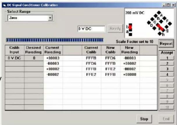
text_image
DC Signal Conditioner Calibration Select Range Zero 200 mV DC 0 V DC Ready 0 V DC 0 V DC Desired Reading Current Reading Current Calib New Calib New Reading 0 V DC 0 •00003 FFFB FFD6 -00003 -00003 FFD6 FFF8 •00002 •00002 FFFB FFE2 -00002 -00002 FFE2 FFFB •00000 Repeat Accept 1 2 3 4 5 6 7 8 9 10 Stop End| MENU KEY | S | 1 | 2 | 3 | 4 | 5 |
| InPut | d | C | V | |||
| SEtuP | 0 | 0 | 0 | 0 | 0 | |
| ConFiG | 0 | 0 | 0 | 0 | 0 | |
| FiLtEr | 0 | 0 | 1 | 1 | 6 | |
| DecPt | d | d | d. | d | d | |
| SCALE | 0 | 0 | 0 | 1 | 0 | |
| OFFSt | 0 | 0 | 0. | 0 | 0 | |
| SEr 1 | 0 | 5 | 0 | |||
| SEr 2 | 0 | 0 | 1 | 1 | ||
| Loc 1 | 0 | 0 | 0 | 0 | 0 | |
| Loc 2 | 0 | 0 | 1 | 0 | ||
| Loc 3 | 0 | 0 | 0 | 0 | ||
panel programming sequence, where each row corresponds to a menu item selected by the key, and the seven data columns correspond to values entered via the and keys.
Click on any step in the sequence to bring up a detailed help window.
Click on Print for a hardcopy, which you can then use as an instruction sheet to program your meter via its front panel.
Click on Main Menu => File => Save Setup As to save your setup to disk and have an electronic record.
21. CUSTOM CURVE LINEARIZATION
Curve.exe is a DOS-based, executable PC program used to set up an Extended meter so that the readings have a user-defined, non-linear relationship with the input signal. The calculated linearizing parameters are downloaded into non-volatile memory of the meter. For example, it allows a meter to correct for transducer nonlinearity or to display volume of an irregularly shaped tank based on liquid level. The curve-fitting algorithm uses quadratic segments of varying length and curvature, and provides diagnostics to estimate curve fitting errors. The program is self-prompting, avoiding the need for a detailed printed manual. This manual section is only intended as an introduction and get-started guide.

text_image
Tank Volume from Pressure at the Bottom of the Tank TANK 4-20 mAPREREQUISITES
1) PC-compatible computer with an available RS232 or USB port.
2) Extended meter.
3) An RS232 or USB board in the meter. This board can be removed following meter setup.
4) An RJ11-to-DB9 RS232 cable or a USB cable to connect the meter to the PC (see Section 1, Ordering Guide).
5) Curve.exe software (downloadable from the web at no charge).
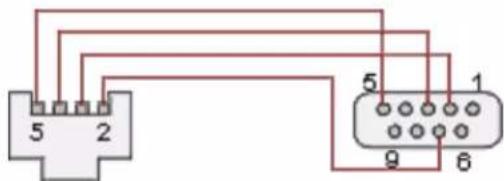
text_image
5 2 5 1 9 6RJ11-to-DB9 RS-232 cable
GETTING STARTED
Download curve.exe into the same directory that will contain your data files, such as c:\curves. Set the meter baud rate to 9600. To do so, press the → key to get to SEr 1, then set the entry to 050. Set the meter address to 1. To do so, press the → key to get to SEr 2, then set the entry to 0011. To execute the program from Windows, simply double-click on curve.exe, which is an executable file. Follow the steps on computer screens, which will prompt you and provide extensive information. Pressing R (Enter) returns to the main menu.
You will be given the choice to enter your data in one of four modes:
1) Text file entry mode, with an X value in one column and a Y value in another. There can be additional columns, which are ignored. The file must have a DOS name of up to 8 characters and the extension .RAW. There can be from 5 to 180 rows. X is the input value and should be in the unit of measure for which the meter was set up, such as mΩ, Ω, mA or A. Y is the desired corresponding reading and can range from -99999 to 99999 with any decimal point.
2) 2-coordinate keyboard entry mode, where an actual X input signal is applied, and the desired Y reading is entered from the keyboard.
3) 2-coordinate file entry mode, where an actual X input signal is applied, and the desired Y reading is provided from a file.
4) Equation entry mode, where the coefficients of a polynomial Y = K1X^P1 + K2X^P2 + K3^*X^P3 + are entered. Up to 20 terms are allowed. An offset can be built into X.
You will be asked if your DPM has a revision of DPM4L or later. You will normally select 2 (yes), since revision DPM4L started to ship in August 2000.
You will be asked to supply the following:
LOW X-COORDINATE ΩALUE >
LOW INPUT MEASUREMENT ΩALUE >
HIGH X-COORDINATE ΩALUE >
HIGH INPUT MEASUREMENT ΩALUE >
This informs the computer of your signal conditioner jumper settings. Enter 0 and 0 for the two LOW values. For HIGH X, enter your signal conditioner jumper range in the same units of measure that you will be using in your *.RAW data input file. Enter 20 for 20 mΩ or 20Ω. Enter 200 for 200 mΩ or 200Ω. Enter 5 for 5A AC or DC. For HIGH INPUT MEASUREMENT ΩALUE, enter 20000, except for 5A DC, where you should enter 5000.
Position of the decimal point from 6=X.XXXXX, 5=XX.XXX, 4=XXX.XXX, 3=XXXX.XX, 2=XXXX.X, 1=XXXXXX (for DPMs, the leading X is a blank). Specify the same position that you specified in the dEc.Pt decimal point menu selection.
Follow the steps on the screens to finish generating the custom curve. When prompted to download the file to the meter, select Y. When prompted to set the meter to custom curve mode, also select Y.
KEYPAD CONTROL
You can take a meter in and out of custom curve linearization using the meter keypad. From the Menu mode, press the key to get to ConFC, then set the fifth digit to either 1 (normal linear operation) or to 1 (custom curve operation). This fifth digit will only be displayed with an Extended meter.
FILES USED OR CREATED BY CURVE.EXE
1) *.RAW is the raw input file generated by all four data entry methods.
2) *.DVD adds three columns from which the smoothness of the input data and obvious input errors can be judged. The more data points and the smoother the data, the better the curve fit.
3) *.NUM lists Y readings prior to custom curve linearization and addition of the decimal point.
4) *.CCF is an internal file used by the software.
5) *.SIM lists simulated linearized meter readings and calculated corresponding errors.
6) *.PRM contains the final hex data that is downloaded into the meter.
22. METER CALIBRATION
All analog input and analog output ranges of the meter have been digitally calibrated at the factory prior to shipment using calibration equipment certified to NIST standards. Calibration constants are stored digitally in non-volatile memory in EEPROM on the signal conditioner board and analog output board. As a result, these boards may be mixed and interchanged without requiring meter recalibration. Digital calibration eliminates much of circuitry that would be associated with analog calibration, providing superior long term accuracy and stability.
If recalibration is required, the meter may be returned to the factory or to any authorized distributor. Easy calibration of DC, AC and load cell signal conditioner ranges is possible using the Instrument Setup software, as described in Section 20. To allow computer aided calibration, an RS232 or RS485 interface card must be installed in the meter. This card may be installed temporarily and be removed following calibration. Step-by-step instructions and advanced calibration software are available from the factory.
23. SPECIFICATIONS
Meter Display
Type ....5 LED, 7-segment, 14.2mm (.56") high digits & 3 LED indicators Color....Red or green Range....-99999 to +99999 and -99990 to +99990
A to D Conversion
Technique (Pat.5,262,780).... Concurrent Slope ^TM Read Rate ....60/s for 60 Hz NMR, 50/s for 50 Hz NMR Output Update Rate ....56/s at 60 Hz, 47/s at 50 Hz Display Update Rate ....3.5/s at 60 Hz, 3/s at 50 Hz
Noise Rejection
CMΩ from DC to 60 Hz....Withstand 250Ωac Dielectric strength....3.5 kΩ ac for 5 sec, 2.3 kΩ ac for 1 min CMR from DC to 60 Hz....130 dB NMR at 50/60 Hz....90 dB with minimum digital filtering
Control Inputs (CMOS/TTL levels, logic 0 = tied to digital ground, logic 1 = open)
/ Hold input ....Logic 0 holds display and outputs / Peak or Ωalley input ....Logic 0 displays peak/valley value / Tare input ....Logic 0 offsets input value to zero / Tare Reset....Logic 0 resets Tare value to zero / Reset input ....Logic 0 resets all meter functions / Function Reset input ....Logic 0 resets peak values and alarms / Decimal Point input ....Overrides internal DP selections and controls DP position / Display Blank input....Logic 0 shuts off the display
Power Requirements
Input Ωoltage rating (standard)....85-264 Ωac or 90-300 Ωdc (DC range not UL approved) Input Ωoltage rating (low voltage option) .... 12-32 Ωac or 10-48 Ωdc Power Line Frequency .... DC and 47-63 Hz Power Consumption, Max .... 5 Watts
Excitation Outputs
Ωoltage & Current Levels (jumper selectable) .... 5 Ωdc ±5%, 100 mA max 10 Ωdc ±5%, 120 mA max 24 Ωdc ± 5%, 40 mA max Excitation Output Ripple....100 mΩp max Isolation from power and outputs....250 Ωac Insulation dielectric strength to power and outputs....3.5 kΩ ac for 5 sec, 2.3 kΩ ac for 1 min Isolation to signal common....50 Ωdc
Input Types, Ranges, Resolution, Error at 25°C
DC Volts
| Range Resol. Resist. Error | |||
| 200.00 mV | 10 μV | 1 GΩ | |
| 2.0000 V | 100 μV | 1 GΩ | 0.01% |
| 20.000 V | 1 mV | 10 MΩ | of FS |
| 200.00 V | 10 mV | 10 MΩ | ±2 cts |
| 300.0 V | 100 mV | 10 MΩ | |
DC Amps
| Range Resol. Resist. Error | |||
| 2.0000 mA | 0.1 μA | 100 Ω | 0.01% of FS ±2 cts |
| 20.000 mA | 1 μA | 10 Ω | |
| 200.00 mA | 10 μA | 1 Ω | |
| 5.000 A 1 | mA 0.01 Ω | 0.1% of FS ±5 cts | |
True RMS Volts (0% to 100% of Full Scale, 0 Hz and 10 Hz to 10 kHz, crest factor 3.0)
| Range Resol. Resist. Error | |||
| 200.00 mV | 10 μV | 22 MΩ | 0.1% of FS ±2 cts |
| 2.0000 V | 100 μV | 22 MΩ | |
| 20.000 V | 1 mV | 1 MΩ | |
| 200.00 V | 10 mV | 1 MΩ | |
| 600.0 V 100 mV 1 MΩ 2V | |||
True RMS Amps (0% to 100% of Full Scale 0 Hz and 10 Hz to 10 kHz, crest factor 3.0)
| Range Resol. Resist. Error | |||
| 2.0000 mA | 0.1 μA | 100 Ω | 0.1% |
| 20.000 mA | 1 μA | 10 Ω | of FS |
| 200.00 mA | 10 μA | 1 Ω | ±2 cts |
| 5.000 A 1 | mA 0.01 Ω | 20 mA | |
Resistance Measurement
| Range | Resolution | Error |
| 0-20.000Ω | 1 mΩ | |
| 0-200.00Ω | 10 mΩ | 0.01% |
| 0-2000.0Ω | 100 mΩ | of FS |
| 0-20000 Ω | 1 Ω | ±2 cts |
| 0-200.00 kΩ | 10 Ω |
Thermocouple (0.1°, 1° resolution)
| Type | Range | Error |
| J | -210 to 760°C-347to 1400°F | .01% FS ±0.09°C.01% FS ±0.16°F |
| K | -244 to 1372°C-408to 2501°F | .01% FS ±0.10°C.01% FS ±0.17°F |
| T | 0 to 400°C-257 to 0°C | .01% FS ±0.03°C.01% FS ±0.20°C |
| 32 to 752°F-430 to 32°F | .01% FS ±0.05°F.01% FS ±0.36°F | |
| E | -240 to 1000°C-400 to 1830°F | .01% FS ±0.18°C.01% FS ±0.32°F |
| N | -245 to 1300°C-410 to 2370°F | .01% FS ±0.10°C.01% FS ±0.17°F |
| S | -46 to +1768°C-51 to +3213°F | .01% FS ±0.12°C.01% FS ±0.22°F |
| R | -45 to 1768°C-49 to 3214°F | .01% FS ±0.17°C.01% FS ±0.31°F |
RTD (0.01°, 0.1°, 1° resolution)
| Type | Range | Error |
| Pt 100Ω.00385 | -202 to 850°C-331 to 1562°F | .01% FS ±0.03°C.01% FS ±0.05°F |
| Pt 100Ω.003925 | -202 to 631°C-331 to 1168°F | .01% FS ±0.04°C.01% FS ±0.07°F |
| Ni 120Ω.00672 | -80 to 260°C-112 to 500°F | .01% FS ±0.05°C.01% FS ±0.09°F |
| Cu 10Ω.00427 | -97 to 260°C-143 to 500°F | .01% FS ±0.05°C.01% FS ±0.09°F |
Ratio, Potentiometer Follower, Strain
| Range Resol. Resistance | Error | ||
| 200.00 mV | 10 μV | 1 GΩ | 0.01% |
| 2.0000 V | 100 μV | 1 GΩ | of FS |
| 20.000 V | 1 mV | 1 MΩ | ±2 cts |
Load Cell Input
| Range Resolution | Resistance | Zero Range | Span Range | Error | |
| 20.000 mV | 1 μV | ||||
| 50.000 mV | 2.5 μV | ||||
| 100.00 mV | 5 μV | 1 GΩ | -99999 to 99999 | 0 to ±99,999 | 0.01% of FS ±2 cts |
| 250.00 mV | 12.5 μV | ||||
| 500.00 mV | 25 μV |
Thermocouple Accuracy
Span Tempco....0.003% of reading/°C
0.0015% of reading/°C for load cell meter
Zero Tempco 0.2 μV/°C
Reference Junction Accuracy ....1°C, 10°C to 40°C
Dual & Quad Relay Options
Power to Relay Option ....Powered by meter
Setpoint Setup.... Via front panel pushbuttons or RS232/485
Update Rate 56/s at 60 Hz, 47/s at 50 Hz
Response to input signal (min)......Display update rate
Input Signal (selectable)....Filtered or unfiltered input signal
Actuation Modes (selectable) ..... Above or below setpoint, latching or non-latching, disabled
Output Time Delay (selectable) 1 to 128 readings
Front Panel Enable / Lockout Modes (selectable)....1) Display and change setpoints
2) Display but do not change setpoints
3) Neither display nor change setpoints
Alarm Status Indication ....2 or 4 red LED lamps
Status Indication Setup (selectable) ....Lit when output is ON or OFF, or disabled
Form C, SPDT Relay Output:
AC Rating 8A @ 240 Vac
DC Rating....8A @ 24 Vdc
Isolation rating between signal common and contacts 250 Vac
Insulation dielectric strength between signal common and contacts ....
3.5 kV ac for 5 sec, 2.3 kV ac for 1 min
Form A, SPST Solid State Relay Output:
AC Rating....120 mA @ 140 Vac
DC Rating....120 mA @ 180 Vdc
Isolation rating between signal common and contacts 250V ac
Insulation dielectric strength between signal common and contacts ....
3.5 kV ac for 5 sec, 2.3 kV ac for 1 min
Analog Output Option
Power to Analog Output Option....Powered by meter
Output Levels 0-20 mA, 4-20 mA, 0-10V, -10 to +10V
Voltage Compliance, 0-20 mA Output 12V (0-600 Ohm load)
Current Compliance, 0-10V, -10 to +10V Output.....2 mA (5 kOhm or higher load)
| Accuracy | Meter input accuracy ±0.02% of full scale analog output |
| Resolution | 16 bit (1 part in 65,536) |
| Response Time | 50/60Hz update rate |
| Scaling of Reading for Zero Output | -99,999 to +99,999 |
| Scaling of Reading for Full Scale Output | -99,999 to +99,999 |
| Isolation rating between signal common and analog output | 250Ω ac |
| Insulation dielectric strength between signal common and analog output | 3.5 kΩ ac for 5 sec, 2.3 kΩ ac for 1 min |
Serial Interface Option (USB, RS232, RS485, RS485-Modbus boards)
| Output Types....RS232, RS485, RS485-Modbus, USB....USB-to-RS485 converter | |
| Power to Interface Option....Powered by meter | |
| RS485 Wiring....Half or full duplex | |
| Baud Rates....300, 600, 1200, 2400, 4800, 9600, 19200 | |
| Serial Protocols....Custom ASCII, Modbus RTU, Modbus ASCII (selectable) | |
| Signal Levels....Meet RS232, RS485, USB standards | |
| Isolation rating between signal common and serial I/O....250Ω ac | |
| Insulation dielectric strength between signal common and serial I/O....3.5 kΩ ac for 5 sec, 2.3 kΩ ac for 1 min | |
| Option Board Connectors: | |
| RS232....Single RJ11 jack | |
| RS485....Two RJ11 jacks (for daisy chaining with 6-wire data cables) | |
| RS485 Modbus....Two RJ45 jacks (for daisy chaining with 8-wire data cables) | |
| USB....USB type B plug | |
| USB-to-RS485 converter....USB type B plug plus RJ11 jack to RS485 bus |
Environmental
| Operating Temperature | 0°C to 55°C |
| Storage Temperature | -40°C to 85°C |
| Relative Humidity | 95% from 0°C to 40°C, non-condensing |
| Case | NEMA-4X (IP65) from front when panel mounted (not verified for UL) |
| Shock | 10 G at 1 kHz, applied in X, Y, Z axes |
| Ωibration | 15 Hz to 150 Hz, 1 mm to 2 mm amplitude, 20 G max. |
24. GLOSSARY OF TERMS
Adaptive Filter Threshold
A threshold which causes an adaptive moving average filter to be reset to the latest reading when the accumulated difference between individual readings and the filtered reading exceeds that threshold. Adaptive moving average filtering allows a meter to respond rapidly to actual changes in signal while filtering out normal noise. The accumulated difference is also reset to zero when the latest reading has a different polarity than the filtered reading. A low adaptive filter threshold is normally selected. A high filter threshold should be selected if the signal has large transients.
Alarm, Latched
An alarm which stays actuated until reset.
Latched alarms can shut down machinery or a process when an operating limit has been exceeded, or maintain an alarm condition until acknowledged by an operator.
Alarm, Non-latched
An alarm which changes state automatically when the reading rises above a specified limit and changes back automatically when the reading falls below a limit.
Autofilter
A selectable digital filter mode which automatically selects an appropriate moving average filter time constant from 0.08 sec to 9.6 sec for the encountered noise condition.
Auto-tare
A selectable meter operating mode, where the first reading following power-on or meter reset is used to zero the display. Further readings are then relative to this new zero.
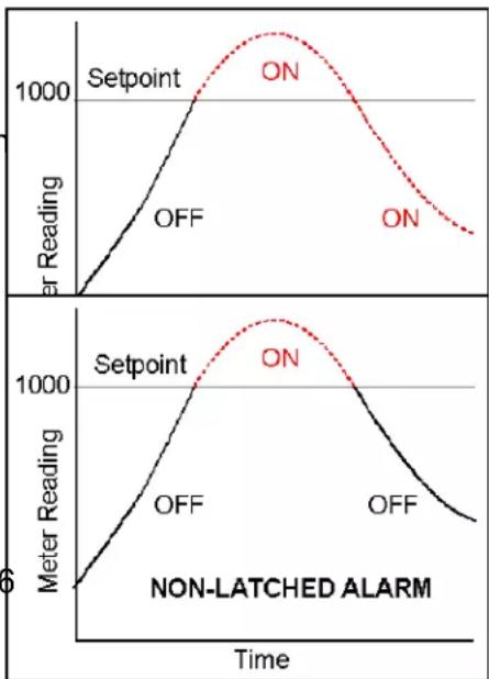
line
| Time | Setpoint OFF (Litter Reading) | ON (Litter Reading) | |------|-------------------------------|---------------------| | 0 | 0 | 0 | | 1 | ~500 | ~1000 | | 2 | ~1000 | ~1200 | | 3 | ~1200 | ~1100 | | 4 | ~1100 | ~900 | | 5 | ~900 | ~700 | | 6 | ~700 | ~500 | | 7 | ~500 | ~300 | | 8 | ~300 | ~100 | | 9 | ~100 | ~50 | | 10 | ~50 | ~25 | | 11 | ~25 | ~10 | | 12 | ~10 | ~5 | | 13 | ~5 | ~2 | | 14 | ~2 | ~1 | | 15 | ~1 | ~0.5 | | 16 | ~0.5 | ~0.2 | | 17 | ~0.2 | ~0.1 | | 18 | ~0.1 | ~0.05 | | 19 | ~0.05 | ~0.02 | | 20 | ~0.02 | ~0.01 | | 21 | ~0.01 | ~0.005 | | 22 | ~0.005 | ~0.002 | | 23 | ~0.002 | ~0.001 | | 24 | ~0.001 | ~0.0005 | | 25 | ~0.0005 | ~0.0002 | | 26 | ~0.0002 | ~0.0001 | | 27 | ~0.0001 | ~0.00005 | | 28 | ~0.00005 | ~0.00002 | | 29 | ~0.00002 | ~0.00001 | | 30 | ~0.00001 | ~0.000005 | | 31 | ~0.000005 | ~0.000002 | | 32 | ~0.000002 | ~0.000001 | | 33 | ~0.000001 | ~0.0000005 | | 34 | ~0.0000005 | ~0.0000002 | | 35 | ~0.0000002 | ~0.0000001 | | 36 | ~0.0000001 | ~0.000 | | 37 | ~5 | ~5 | | 38 | ~2 | ~2 | | 39 | ~1 | ~1 | | 40 | ~1 | ~1 | | 41 | ~1 | ~1 | | 42 | ~1 | ~1 | | 43 | ~1 | ~1 | | 44 | ~1 | ~1 | | 45 | ~1 | ~1 | | 46 | ~1 | ~1 | | 47 | ~1 | ~1 | | 48 | ~1 | ~1 | | 49 | ~1 | ~1 | | 50 | ~1 | ~1 | | 51 | ~1 | ~1 | | 52 | ~1 | ~1 | | 53 | ~1 | ~1 | | 54 | ~1 | ~1 | | 55 | ~1 | ~1 | | 56 | ~1 | ~1 | | 57 | ~1 | ~1 | | 58 | ~1 | ~1 | | 59 | ~1 | ~1 | | 60 | ~1 | ~1 | | 61 | ~1 | ~1 | | 62 | ~1 | ~1 | | 63 | ~1 | ~1 | | 64 | ~1 | ~1 | | 65 | ~1 | ~1 | | 66 | ~1 | ~1 | | 67 | ~1 | ~1 | | 68 | ~1 | ~1 | | 69 | ~1 | ~1 | | 70 | ~1 | ~1 | | 71 | ~1 | ~1 | | 72 | ~1 | ~1 | | 73 | ~1 | ~1 | | 74 | ~1 | ~1 | | 75 | ~1 | ~1 | | 76 | ~1 | ~1 | | 77 | ~1 | ~1 | | 78 | ~1 | ~1 | | 79 | ~1 | ~1 | | 80 | ~1 | ~1 | | 81 | ~1 | ~1 | | 82 | ~1 | ~1 | | 83 | ~1 | ~1 | | 84 | ~1 | ~1 | | 85 | ~1 | ~1 | | 86 | ~1 | ~1 | | 87 | ~1 | ~1 | | 88 | ~1 | ~1 | | 89 | ~1 | ~1 | | 90 | ~1 | ~1 | | 91 | ~1 | ~1 | | 92 | ~1 | ~1 | | 93 | ~1 | ~1 | | 94 | ~1 | ~1 | | 95 | ~1 | ~1 | | 96 | ~1 | ~1 | | 97 | ~1 | ~1 | | 98 | ~1 | ~1 | | 99 | ~1 | ~1 | | 100 | ~1 | ~1 | Non-LATCHED ALARMBatch Average Filter
A digital filter mode which averages 16 readings and then displays the average. Readings are taken at 60/sec with 60 Hz power and 50/sec with 50 Hz power.
Counts
The reading displayed on the panel meter ignoring the decimal point.
Custom ASCII Protocol
A simplified, short protocol for use with these panel meters. It allows 31 digital addresses. Not an industry-standard protocol, like the more complex Modbus protocol, which is also offered with the meters.
Deviation Band
A band in counts which controls relay action symmetrically around a setpoint. The relay actuates when the reading falls within the deviation band, and de-actuates when the reading falls outside. A limit (e.g., 50 counts) is set up around both sides of the setpoint to create a deviation band (e.g., 100 counts). Setting up a passband around a setpoint is often used for component testing.
Deviation limits are programmed by entering menu item dEU1b for Alarm 1 and dEU2b for Alarm 2. The deviation band will be equal to two limits.
Display Blank A rear panel input which blanks the display when the input is tied to logic ground by a switch or 0Ω is applied (logic level true). The meter display will light when the input is open or is held at +5Ω (logic level false).
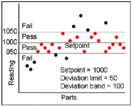
scatter
| Parts | Reading | Status | |-------|---------|--------| | 1 | 950 | Fail | | 2 | 960 | Fail | | 3 | 970 | Fail | | 4 | 980 | Fail | | 5 | 990 | Fail | | 6 | 1000 | Pass | | 7 | 1010 | Pass | | 8 | 1020 | Pass | | 9 | 1030 | Pass | | 10 | 1040 | Pass | | 11 | 1050 | Pass | | 12 | 1060 | Setpoint | | 13 | 1070 | Setpoint | | 14 | 1080 | Setpoint | | 15 | 1090 | Setpoint | | 16 | 1100 | Setpoint | | 17 | 1110 | Setpoint | | 18 | 1120 | Setpoint | | 19 | 1130 | Setpoint | | 20 | 1140 | Setpoint | | 21 | 1150 | Setpoint | | 22 | 1160 | Setpoint | | 23 | 1170 | Setpoint | | 24 | 1180 | Setpoint | | 25 | 1190 | Setpoint | | 26 | 1200 | Setpoint | | 27 | 1210 | Setpoint | | 28 | 1220 | Setpoint | | 29 | 1230 | Setpoint | | 30 | 1240 | Setpoint | | 31 | 1250 | Setpoint | | 32 | 1260 | Setpoint | | 33 | 1270 | Setpoint | | 34 | 1280 | Setpoint | | 35 | 1290 | Setpoint | | 36 | 1300 | Setpoint | | 37 | 1310 | Setpoint | | 38 | 1320 | Setpoint | | 39 | 1330 | Setpoint | | 40 | 1340 | Setpoint | | 41 | 1350 | Setpoint | | 42 | 1360 | Setpoint | | 43 | 1370 | Setpoint | | 44 | 1380 | Setpoint | | 45 | 1390 | Setpoint | | 46 | 1400 | Setpoint | | 47 | 1410 | Setpoint | | 48 | 1420 | Setpoint | | 49 | 1430 | Setpoint | | 50 | 1440 | Setpoint | | 51 | 1450 | Setpoint | | 52 | 1460 | Setpoint | | 53 | 1470 | Setpoint | | 54 | 1480 | Setpoint | | 55 | 1490 | Setpoint | | 56 | 1500 | Setpoint | | 57 | 1510 | Setpoint | | 58 | 1520 | Setpoint | | 59 | 1530 | Setpoint | | 60 | 1540 | Setpoint | | 61 | 1550 | Setpoint | | 62 | 1560 | Setpoint | | 63 | 1570 | Setpoint | | 64 | 1580 | Setpoint | | 65 | 1590 | Setpoint | | 66 | 1600 | Setpoint | | 67 | 1610 | Setpoint | | 68 | 1620 | Setpoint | | 69 | 1630 | Setpoint | | 70 | 1640 | Setpoint | | 71 | 1650 | Setpoint | | 72 | 1660 | Setpoint | | 73 | 1670 | Setpoint | | 74 | 1680 | Setpoint | | 75 | 1690 | Setpoint | | 76 | 1700 | Setpoint | | 77 | 1710 | Setpoint | | 78 | 1720 | Setpoint | | 79 | 1730 | Setpoint | | 80 | 1740 | Setpoint | | 81 | 1750 | Setpoint | | 82 | 1760 | Setpoint | | 83 | 1770 | Setpoint | | 84 | 1780 | Setpoint | | 85 | 1790 | Setpoint | | 86 | 1800 | Setpoint | | 87 | 1810 | Setpoint | | 88 | 1820 | Setpoint | | 89 | 1830 | Setpoint | | 90 | 1840 | Setpoint | | 91 | 1850 | Setpoint | | 92 | 1860 | Setpoint | | 93 | 1870 | Setpoint | | 94 | 1880 | Setpoint | | 95 | 1890 | Setpoint | | 96 | 1900 | Setpoint | | 97 | 1910 | Setpoint | | 98 | 1920 | Setpoint | | 99 | 1930 | Setpoint | | 100 | - | Setpoint = - | Deviation limit = -50; Deviation band = -5.5m; Deviation band = -5.7m.Extended Meter
A digital panel meter with an enhanced microcomputer that provides added capabilities, specifically linearization of nonlinear inputs and display of rate of change from successive readings.
Full Scale The maximum input signal range for which the meter has been configured. For example, the most sensitive full scale for the load cell meter is ±20 m (signal range from -20 m to +20 m ).
Function Reset
A rear panel control input which resets Peak, alley and any latched alarms when the input is tied to logic ground by a switch or 0 is applied (logic level true). To reset the value again, the input must be open or 5 applied (logic level false) and then set low.
Ground Loop A closed conductive path in external ground wiring that allows stray currents to flow in ground wiring, creating ground noise. The meters in this manual minimize ground loop problems by mutually isolating the grounds associated with meter power, signal input, and all output and communication options.
Jumper A push-on component which provides a short between two adjacent posts on a circuit board. Jumpers are used to configure signal conditioner boards for specific signal types and full scale ranges, and to configure power supply and communications boards for various modes of operation. Unused jumpers are stored by pushing one side over an unused post.
Hysteresis Band
A band which controls relay action symme-
trically around a setpoint. The relay closes (or opens) when the reading goes above the setpoint plus one hysteresis limit, and opens (or closes) when the reading falls below the setpoint less one hysteresis limit. A narrow hysteresis band is often used to minimize relay chatter around a setpoint due to electrical noise or signal feedback caused by load switching. A wide hysteresis
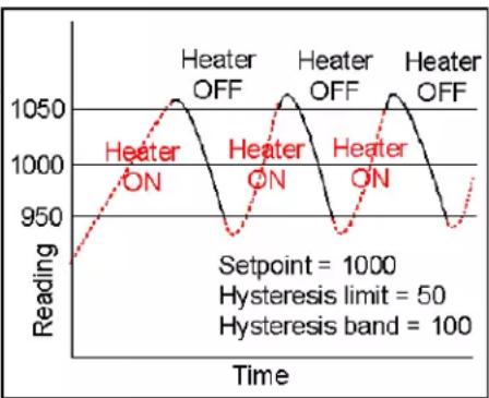
line
| Time | Reading | |------|---------| | 0 | 950 | | 1 | 1000 | | 2 | 1050 | | 3 | 1000 | | 4 | 950 | | 5 | 1000 | | 6 | 1050 | | 7 | 1000 | | 8 | 950 | | 9 | 1000 | | 10 | 1050 | | 11 | 1000 | | 12 | 950 | | 13 | 1000 | | 14 | 1050 | | 15 | 1000 | | 16 | 950 | | 17 | 1000 | | 18 | 1050 | | 19 | 1000 | | 20 | 950 | | 21 | 1000 | | 22 | 1050 | | 23 | 1000 | | 24 | 950 | | 25 | 1000 | | 26 | 1050 | | 27 | 1000 | | 28 | 950 | | 29 | 1000 | | 30 | 1050 | | 31 | 1000 | | 32 | 950 | | 33 | 1000 | | 34 | 1050 | | 35 | 1000 | | 36 | 950 | | 37 | 1000 | | 38 | 1050 | | 39 | 1000 | | 40 | 950 | | 41 | 1000 | | 42 | 1050 | | 43 | 1000 | | 44 | 950 | | 45 | 1000 | | 46 | 1050 | | 47 | 1000 | | 48 | 950 | | 49 | 1000 | | 50 | 1050 | | 51 | 1000 | | 52 | 950 | | 53 | 1000 | | 54 | 1050 | | 55 | 1000 | | 56 | 950 | | 57 | 1000 | | 58 | 1050 | | 59 | 1000 | | 60 | 950 | | 61 | 1000 | | 62 | 1050 | | 63 | 1000 | | 64 | 950 | | 65 | 1000 | | 66 | 1050 | | 67 | 1000 | | 68 | 950 | | 69 | 1000 | | 70 | 1050 | | 71 | 1000 | | 72 | 950 | | 73 | 1000 | | 74 | 1050 | | 75 | 1000 | | 76 | 950 | | 77 | 1000 | | 78 | 1050 | | 79 | 1000 | | 80 | 950 | | 81 | 1000 | | 82 | 1050 | | 83 | 1000 | | 84 | 950 | | 85 | 1000 | | 86 | 1050 | | 87 | 1000 | | 88 | 950 | | 89 | 1000 | | 90 | 1050 | | 91 | 1000 | | 92 | 950 | | 93 | 1000 | | 94 | 1050 | | 95 | 1000 | | 96 | 950 | | 97 | 1000 | | 98 | 1050 | | 99 | 1000 | | 100+ | |band can be used for control applications, such as turning on a fill pump when the tank level has reached a lower limit and shutting off the pump when the tank level has reached an upper limit. The hysteresis band will be equal to two hysteresis limits.
Menu Mode The meter programming mode used for input and range selection, meter setup, and meter configuration. Entered into from the Run mode by pressing the MENU key. The Menu mode can be locked out completely by a jumper.
Meter Hold A rear panel input which freezes the meter display and all meter outputs while that input is tied to logic ground by a switch or is held at 0Ω (logic level true). The meter will resume operation when the input is allowed to float or is held at +5Ω (logic level false).
Modbus An industry-standard serial communications protocol which allows devices by different manufacturers to be digitally addressed by a PC on the same communication line, with up to 247 digital addresses. More complex than the Custom ASCII protocol, which is also supported by these meters.
Moving Average Filter
A digital filter mode which displays a weighting moving average of readings.
Readings are taken at 60/sec with 60 Hz power and 50/sec with 50 Hz power. Display update rates remain 3.5/sec with 60 Hz power and 3.0/sec with 50 Hz power. There are eight moving average modes:
Old average x 1/2 + new reading x 1/2 (equivalent to 0.08 sec RC time constant).
Old average x 3/4 + new reading x 1/4 (equivalent to 0.15 sec RC time constant).
Old average x 7/8 + new reading x 1/8 (equivalent to 0.3 sec RC time constant).
Old average x 15/16 + new reading x 1/16 (equivalent to 0.6 sec RC time constant).
Old average x 31/32 + new reading x 1/32 (equivalent to 1.2 sec RC time constant).
Old average x 63/64 + new reading x 1/64 (equivalent to 2.4 sec RC time constant).
Old avg. x 127/128 + new reading x 1/128 (equivalent to 4.8 sec RC time constant).
Old avg. x 255/256 + new reading x 1/256 (equivalent to 9.6 sec RC time constant).
Offset A constant adder used for the displayed reading. This is the term b in the straight line formula y = mx + b , where y is the displayed reading in counts, m is the scale factor, x is the measured reading in counts, and b is the offset. For direct readout in (milli)volts or (milli)amps, offset is 0.
Peak Display The maximum (or most positive) reading since that maximum was last reset. Reset can be via the meter front panel, an external input, or a software command. The displayed value can reflect the filtered or unfiltered readings.
Process Signal
A signal whose display requires setup of scale and offset settings for display in engineering units. A classical process signal is 4-20 mA, where the 4 mA and 20 mA end points can each correspond to a desired meter reading.
Rate of Change Meter
A configuration mode of the Extended meter which allows the display of rate based on successive readings. The conversion to engineering units is achieved with the combination of a multiplier from 0.1 to 10,000 and a scale factor.
Reading The value displayed by the meter. "Taking a reading" is the action of the meter to make an analog-to-digital conversion. Readings are taken at 60/sec with 60 Hz power or 50/sec with 50 Hz power, and are displayed with an update rate of 3.5/sec with 60 Hz power or 3.0/sec with 50 Hz power.
Remote Display
A display mode which allows the meter to serve as a remote display to another meter when connected to it by a 4-wire phone cord. Also allows the meter to transmit raw measurement data to a computer and then display processed data from the computer. A serial communications option board is required in the meter. If such a board is not installed or no serial data is received, the meter displays rESEt.
Reset There are three types of Reset:
- Peak and Ωalley Reset. Achieved by simultaneously pressing the RESET and PEAK keys.
- Latched Alarm Reset. Achieved by simultaneously pressing the RESET and ALARMS keys.
- Meter Reset. Causes the meter to reinitialize and take a tare reading when set up for auto-tare. Achieved powering up the meter, by pressing the RESET and MENU keys simultaneously, stepping through all top-level menu choices, grounding a rear panel connector, or supplying an ASCII command. rESEt is displayed briefly.
RS485 Half Duplex
Serial communications implemented with two wires, allowing data transmission in both directions, but not simultaneously.
RS485 Full Duplex
Serial communications implemented with four wires, allowing data transmission in two directions simultaneously.
Run Mode The normal operating mode of the meter, where readings are taken, as opposed to the menu mode.
Scale A constant multiplier used to go from A/D converter counts to displayed counts. This is the slope term m in the straight line formula y = mx + b , where y is the displayed reading in counts, m is the scale factor, x is the measured reading in counts, and b is the offset. For direct readout in (milli)volts or (milli)amps, scale is 1.
Scaling The process of setting scale and offset so that the meter reads properly in engineering units (such as psi).
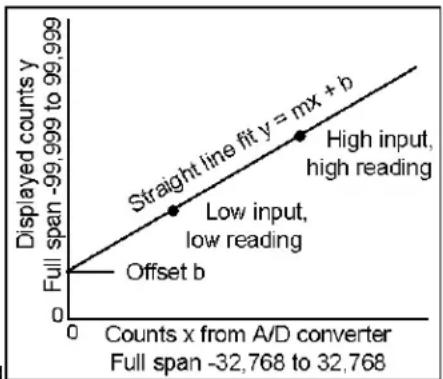
line
| Point Label | Displayed counts y | | :--- | :--- | | Offset b | 0 | | Low input, low reading | 1 | | High input, high reading | 2 | | Straight line fit y = mx + b | 3 |Scaling, Coordinates of 2 Points Method
A scaling method where four numbers are entered manually: low input, desired reading at low input; high input, and desired reading at high input. The meter then applies a straight line fit. The decimal point is set by the separate dEC.Pt menu item.
Scaling, Scale and Offset Method
A scaling method where scale and offset are entered manually.
Scaling, Reading Coordinates of 2 Points Method
A scaling method, where the low and high input values are determined from actual signals. A known low signal is first applied to the meter. That signal is captured as the low input value, and the desired low reading is entered. A known high signal is then applied. That signal is captured as the high input value, and the desired high reading is entered. The meter then applies straight line fit. This scaling method has the advantage of calibrating the transducer and meter as a system. The actual voltage or current at either point does not need to be known. The decimal point is set by the separate dEC.Pt menu item.
Setpoint A value compared to the reading to determine the state of a relay. Term often used interchangeably with “alarm setpoint.” The relay action can by latching or non-latching, utilize a hysteresis band, or utilize a deviation band. Hysteresis bands and deviation bands are specified by two symmetrical limits around the setpoint.
Span The number of counts corresponding to a given signal range.
Split Hysteresis
A hysteresis mode where a setpoint and a single-side hysteresis limit are entered. That limit can be negative or positive. If the limit is negative, the relay will close below the hysteresis limit, for example to turn on a heater, and open when the setpoint is reached. If the limit is positive, the relay will close when that limit is reached, for example to turn on a cooler, and open when the setpoint is reached. Split hysteresis is an alternative to normal hysteresis, where the setpoint is at the center of a symmetrical hysteresis band.

line
| Time | Heater ON | Heater OFF | |------|-----------|------------| | Start | 950 | 1000 | | Peak | 1000 | 1000 | | End | 950 | 1000 |Tare A rear panel input which causes the display to be set to zero when the input is momentarily tied to logic ground by a switch or is held at 0 (logic level true). When the input is allowed to float or is held at +5 (logic level false), the meter displays readings relative to this new zero. A common application is in weighing, where an external Tare button is pressed to read the weight of an empty scale (tare), and tare is then automatically subtracted as a constant from gross weight for display of net weight. Tare can also be used for other applications where a reading relative to starting point is desired.
Valley Display
The minimum (or most negative) reading since that minimum was last reset. Reset can be via the meter front panel, an external input, or a software command. The displayed value can reflect the filtered or unfiltered readings.
Zero When used with process meters, zero is an adjustment so that a given low transducer output reads zero on the meter. Zero is adjusted by programming offset.

DAYTRONIC
Daytronic Corporation