DCS-F4805E - Security Camera D-LINK - Free user manual and instructions
Find the device manual for free DCS-F4805E D-LINK in PDF.

User questions about DCS-F4805E D-LINK
0 question about this device. Answer the ones you know or ask your own.
Ask a new question about this device
Download the instructions for your Security Camera in PDF format for free! Find your manual DCS-F4805E - D-LINK and take your electronic device back in hand. On this page are published all the documents necessary for the use of your device. DCS-F4805E by D-LINK.
USER MANUAL DCS-F4805E D-LINK
This document describes the main functions and operations of the web interface for IP cameras. It includes instructions for:
- Network access
• Network configuration - Troubleshooting
Intended Audience
This document is intended for the following users:
• Technical support engineers
- Maintenance engineers
• IP camera operators
Symbol Conventions
The following symbols are used in this document to indicate important safety information and tips:.
| Symbol | Description |
 DANGER DANGER | Indicates an imminently hazardous situation which, if not avoided, will result in death or serious injury. |
 WARNING WARNING | Indicates a potentially hazardous situation which, if not avoided, could result in death or serious injury. |
 CAUTION CAUTION | Indicates a potentially hazardous situation which, if not avoided, may result in minor or moderate injury. |
 NOTICE NOTICE | Indicates a potentially hazardous situation which, if not avoided, could result in equipment damage, data loss, performance deterioration, or unanticipated results.NOTICE is used to address practices not related to personal injury. |
 NOTE NOTE | Highlights important information, best practices, or useful tips not related to personal injury, equipment damage, or environmental concerns. |
About This Document......i
Contents ...... ii
1 Quick Overview....1
1.1 Login and Logout.... 1
1.2 Change Password ....4
1.3 Homepage Layout 4
1.4 Playback 8
1.5 IVS Setting....10
2 Quick Start Settings ....12
2.1 Local Network.... 12
2.2 Video....14
2.3 Display 17
2.3.1 Access the Display Settings 17
2.3.2 Mode....18
2.3.3 Image Setting 18
2.3.4 Scene Mode....19
2.3.5 Exposure 20
2.3.6 White Balance Setting....22
2.3.7 Day/Night....23
2.3.8 Noise Reduction 27
2.3.9 Image Enhancement....29
2.3.10 Zoom Focus (Only for Some Models) 30
2.4 OSD....32
2.5 Date and Time....35
3 System Settings 37
3.4 Settings....37
3.4.1 Device Information 37
3.4.2 Date and Time....39
3.4.3 System....39
3.4.4 Software Licenses 40
3.5 Change Password 40
3.6 Configure User....40
3.6.1 Add User 40
3.6.2 Online User 43
3.7 Query Device Logs ....44
3.7.1 Query Operation Logs....44
3.7.2 Query Alarm Logs 45
3.7.3 Collect All Logs....46
3.8 Maintain the Device....48
3.8.1 Reboot Device....48
3.8.2 Upgrade the Software Package 49
3.8.3 Restore Device to Factory Settings....50
3.8.4 Export / Import Configuration 51
3.9 Configure Security 54
3.9.1 IP Filter 54
3.9.2 HTTPS Certificate 56
3.9.3 Security Services....57
4 Configure the Network Service ....59
4.4 Basic Settings....59
4.4.1 Local Network 59
4.4.2 Device Port....59
4.4.3 Port Mapping 61
4.4.4 DDNS....62
4.4.5 64
4.4.6 Sct PPPoE 64
4.5 Advanced Settings....66
4.5.1 Set FTP 66
4.5.2 Set SMTP 67
4.5.3 Set HTTPS 69
4.5.4 Procedure 70
4.5.5 Set QOS 70
4.5.6 Set 802.1x 71
4.5.7 Set SNMP 72
4.5.8 View ONVIF....75
4.5.9 Set Platform Access 77
4.5.10 Set Multicast Parameters....80
4.5.11 Set CGI Alarm Service Center....81
5 Configuration Video/Audio 84
5.4 Video....84
5.4.1 Set video 84
5.4.2 Snapshot....84
5.4.3 ROI Parameter 85
5.5 Audio....86
5.5.1 Audio 86
5.5.2 Audible File (Feature available only on certain models) 88
6 Configuration Image....90
6.4 Configure Display....90
6.5 Configure OSD 90
6.6 Configure the Privacy Mask....90
6.7 Configure Video Standard....92
7 Configure Event 93
7.4 Motion Alarm Linkage....93
7.5 Alarm In (Only for Some Models)....96
7.6 Alarm Out (Only for Some Models) 99
7.7 Disk Alarm....100
7.8 Network Alarm .... 101
7.9 Day/Night Switch Alarm....101
7.10 Abnormal Sound Detection (Only for Some Models) 102
7.11 Push Message.... 103
7.12 Flashlight Alarm Output (Only for Some Models) 104
7.13 White Light Alarm Output.... 104
7.14 Red and Blue Light Alarm Output 105
8 Configure Storage Function....107
8.4 Record Strategy 107
8.5 Record Directory....108
8.5.2 Configure the SD Card....110
8.5.3 Configure the FTP....110
8.5.4 Configure the NAS 112
9 IVS Settings....114
9.4 Configure AI Multi-Target....114
9.5 Configure Intelligent Analysis 115
9.5.1 Intrusion....115
9.5.2 Smart Motion 119
9.5.3 Single Line Crossing....120
9.5.4 Double Line Crossing 121
9.5.5 Multi-Loitering 123
9.5.6 Wrong-Way....124
9.6 Configure People Counting....126
9.6.1 Setting 126
9.6.2 Report....128
10 PTZ 130
10.4 Configure PTZ 130
10.4.1 Control and Configure the PTZ (Only for Some Models) 130
10.4.2 Configure the PTZ 131
10.4.3 Configure and Invoke Home / Preset Positions.... 132
10.4.4 Configure and Invoke Tracks.... 134
10.4.5 Configure and Invoke Scans 135
10.4.6 Configure and Invoke Tours 136
10.4.7 Configure Idles.... 139
10.4.8 Configure Timer.... 139
10.4.9 Configure Power UP Action 140
10.4.10 Configure Intelligent Tracking.... 141
10.4.11 Dome PTZ....143
0.5 Configure PTZ Keyboard 143
0.6 Smoke and Flame Detection 145
11 Panoramic Cameras....148
11.4 CVBS Function (Only for Some Models).... 148
11.5 Fisheye Camera.... 149
11.6 Dual-Lens.... 150
11.6.1 Dual-Lens....150
11.7 Panoramic Camera.... 151
11.7.1 RS458....151
11.7.1 IR Led Config 152
11.7.2 CVBS 153
11.8 For Special Cameras 154
11.8.1 General Parameters ...... 154
11.8.2 Illegal Parking (Only for Some Models).... 155
11.8.3 Enter Area 156
11.8.4 Leave Area....156
11.8.5 Heat Map.... 157
Troubleshooting....160
Acronyms and Abbreviations....162
1.1 Login and Logout

CAUTION
Use a supported browser such as Microsoft Edge, Chrome, or Firefox to access the web interface. Other browsers may result in limited functionality.
Login
Step 1 Open THE Chrome browser.
Step 2 Enter the IP address of the IP camera in the address bar (default: 192.168.0.120) and press Enter.
Step 3 On first login: You will be prompted to create a password. After setting the password, you will be directed to the login page.
Note: DHCP is enabled by default. Use the provided tool to search for the camera IP. Default IP: 192.168.0.120.
Important: After changing the password, wait at least 3 minutes before powering off the device to ensure the change is saved. Alternatively, log in again with the new password to verify.
- You can change the system language on the login page.
- Click Login to access the homepage.
D-Link F-Series Camera User Guide Quick Overview
Figure 1-1 Create password

natural_image
Illustration of a camera lens with city skyline and Tower Bridge in background (no text or symbols)Please Create Password
English
User Name
admin
New Password


Please Input New Password
Confirm

Create
Step 1 Enter your username and password to access the system, as shown in Figure 1-2.
- Default username: admin
- Password must be created during initial login.
D-Link F-Series Camera User Guide Quick Overview
Figure 1-2 Login page

natural_image
Illustration of a city skyline with Tower Bridge and modern skyscrapers against a blue background (no text or symbols)English
Please Input Username
Please Input Password
X
Login

NOTE
Note: DHCP is enabled by default. Use the provided tool to search for the camera IP. Default IP: 192.168.0.120.
Important: After changing the password, wait at least 3 minutes before powering off the device to ensure the change is saved. Alternatively, log in again with the new password to verify.
- You can change the system language on the login page.
Step 2 Click Login to access the homepage.
Sign out

text_image
admin Change Password Sign OutClick
Sign Out in the upper right corner to return to login screen.
1.2 Change Password
Description
To change your password:
- Click your username in the upper right corner and select Change Password.
- Or go to Setting > System > Change Password.
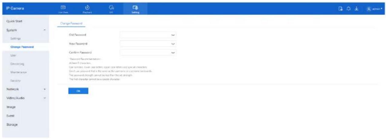
Figure 1-3 Change the default password page
text_image
IP Camera Quick Start System Settings Change Password User Device log Maintenance Security Network Video/Audio Image Event Storage Change Password Out Password New Password Confirm Password *Password Recommendation: All best 5 characters. Use numbers: Lower case letters, upper case letters and special characters. Direct use password that is the next at the computer on a license backwards. The password strength cannot be less than the set strength. The first character cannot be a cyclic character. OKProcedure
Step 1 Enter the old password, new password, and confirm the new password. Step 2 Click OK.
○ A message like "Change your password success!" confirms the change.
○ If the password change fails, a tip or error will be displayed (e.g., "Password must be at least 8 characters").
Step 3 It is recommended to wait three minutes before restarting the device after changing the password. Step 4 Click OK to return to the login page.
1.3 Homepage Layout
The homepage allows you to:
• View real-time video
• Monitor alarms and faults
- Configure system settings
- Change your password
- Log out of the system
Refer to Figure 1-4 for the layout and Table 1-1 for descriptions.
D-Link F-Series Camera User Guide Quick Overview
Figure 1-4 Homepage layout

natural_image
Potted green plant in a white pot with visible roots, placed indoors (no text or symbols)Figure 1-5 PTZ interface
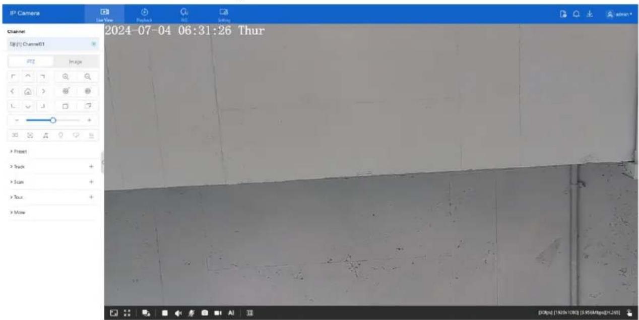
text_image
IP Camera Last View Project View Channel Channel Channel1 PTG Image 2024-07-04 06:31:26 Thur > Preset > Track > Scan > Tour > Move [00fps (1920h 10W) (3.95/8fps)]+265Table 1-1 Elements on the homepage
| No. | Element | Description |
| 1 | Live View | Displays real-time video streams. |
| 2 | Playback | Access recorded videos (requires SD card or NAS with recordings). |
| 3 | IVS setting | Configure AI multi-target features and intelligent analysis (e.g., intrusion, smart motion, single line crossing, double line crossing, multi-loitering, Wrong-Way, general parameters), people counting). |
| 4 | Configuration | Set parameters for Quick Start, System, Network, Audio/Video, Image, Event, and Storage. |
| 5 |  | About the intercom function. |
| 6 |  | Click to view alarm alerts. |
| 7 |  | Displays SD card video backup and download progress. |
| 8 |  | Sign out, change password, view current user. |
| 9 |  | Zoom +/- zoom - (adjust zoom level). |
| 10 |  | Iris +/- iris - (adjust iris value). |
| 11 |  | Near focus /far focus |
| 12 | [14WS] | Auto focus |
| 13 | Image | Set brightness, saturation, contrast and sharpness. |
| 14 |  | Window scale, Adjust display scale for live video. |
| 15 |  | View live video in full-screen mode. |
| 16 |  | Switch between available stream modes (up to 3 depending on model). |
| 17 |  | Pause/Start or Stop live video playback. |
| 18 |  | Enable or disable audio output. |
| 19 |  | Two-way audio. Open or close intercom (the computer should be plugged in microphone prior). |
| 20 | [6RW8] | Click the icon to snapshot the video and save the images to the specified location. |
| 21 | [14ZA] | Record the video and save the file to the specified location. |
| 22 | [2BZ4] | View AI-detected targets (e.g., face, vehicle, human body). |
| 23 |  | Target FrameIntelligent markingTarget frame: Show detection box around targets.Intelligent marking: Display IVS detection areas during live view. |
D-Link F-Series Camera User Guide Quick Overview
| No. | Element | Description |
| 24 |  | Display resolution, frame rate, bit rate, encoding type. |
| 25 |  | I/O output, control the I/O alarm output manually. ClickOpen Close to open alarm or close the alarm |
| 26 |  | Open or close the flashing light manually (available only on special models). |
Figure 1-6 About the intercom function
About The Intercom Function:
×
Description: Only For Enabling the Two-way Audio (Camera) in Chrome on HTTP in Chrome for (local) insecure origins. On HTTPS, all browsers are compatible with Two-way Audio (Camera). HTTP Environment Chrome Opens The Intercom Step:
- Ensure That The Computer is Plugged Into a Usable Microphone Device
- Navigate to 'chrome://flags/#unsafely-treat-insecure-origin-as-secure' in Chrome.
- Find and Enable The 'Insecure Origins Treated as Secure'
4.Add any camera addresses you want to ignore the secure origin policy for on the input box. The comma (',') is used to separate multiple camera addresses. For Example http://192.168.0.123, http://192.168.0.123:8045 5.Left-Click Outside The Input Box to Save It and Relaunch Chrome.
Note: The following instructions apply only when using two-way audio (camera) in Chrome over HTTP (insecure origin). For HTTPS connections, two-way audio is supported by all major browsers.
If using Chrome on HTTP, follow these steps to enable the intercom function:
- Ensure your computer is connected to a working microphone.
- Open Chrome and navigate to: chrome://flags/#unsafely-treat-insecure-origin-as-secure
- Enable the flag: "Insecure origins treated as secure."
- In the input box that appears, enter the IP addresses of the cameras you want to allow, separated by commas.
○ Example:
http://192.168.0.123, http://192.168.1.250:8045
-
Click outside the input box to save your changes.
-
Relaunch Chrome for the changes to take effect.
Figure 1-7 AI multi object interface
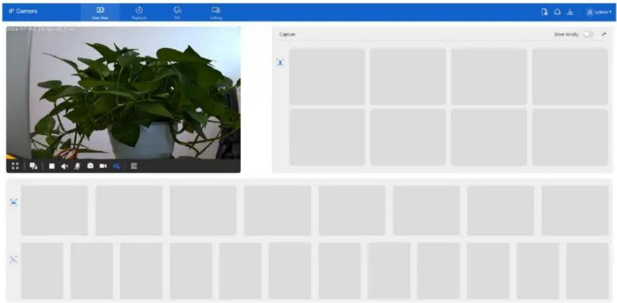
text_image
IP Camera Live View Playback OK Letting 2024-01-02 18:42:18:7:06 Capture Store locally x1.4 Playback
To review recorded footage:
- Click Playback on the web interface.
- If an SD card is installed and enabled, recordings will be available.
Refer to Figure 1-8 for layout and controls.
Figure 1-8 Playback page
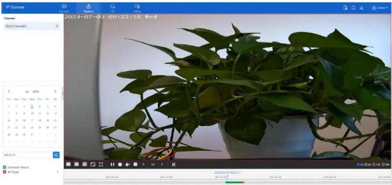
text_image
IP Camera Channel Qj(1) Channel01 2024-07-03 09:22:15 Wed Sun Mon Tue Wed Thu Fri Sat 1 2 3 4 5 6 7 8 9 10 11 12 13 14 15 16 17 18 19 20 21 22 23 24 25 26 27 28 29 30 31 32 33 00:25:15 Schedule Record All Types 2024/07-03 09:22:15 20:20:00 24:18:00 24:17:00 24:16:00 24:15:00D-Link F-Series Camera User Guide
Quick Overview
Table 1-2 Playback function
| No. | Element | Description |
| 1 | Channel | Displays available video channels. |
| 2 | Calender |  |
| 3 |  | All TypesI/O AlarmMotion AlarmDay/Night Switch AlarmAbnormal Audio AlarmIntrusionSmart MotionSingle Line CrossingDouble Line CrossingMulti-LoiteringThe green timeline represents scheduled recording and the red timeline represents alarm recording. The types of alarm recording varies according to model performance. |
| 4 |  | Play one channel's recording. |
| 5 |  | Play two channels' recording. |
| 6 |  | Play four channels' recording. |
| 7 |  | Adjust playback scale. |
| 8 |  | View recording in full-screen mode. |
| 9 |  | Pause or resume playback. |
| 10 |  | Enable or disable audio playback. |
| 11 |  | Capture screenshots from the recording and save the images to a specified location. |
| 12 |  | Fast Forward, 1/16X, 1/8 X, 1/4 X, 1/2 X, 1 X, 2 X, 4 X, 8 X |
D-Link F-Series Camera User Guide Quick Overview
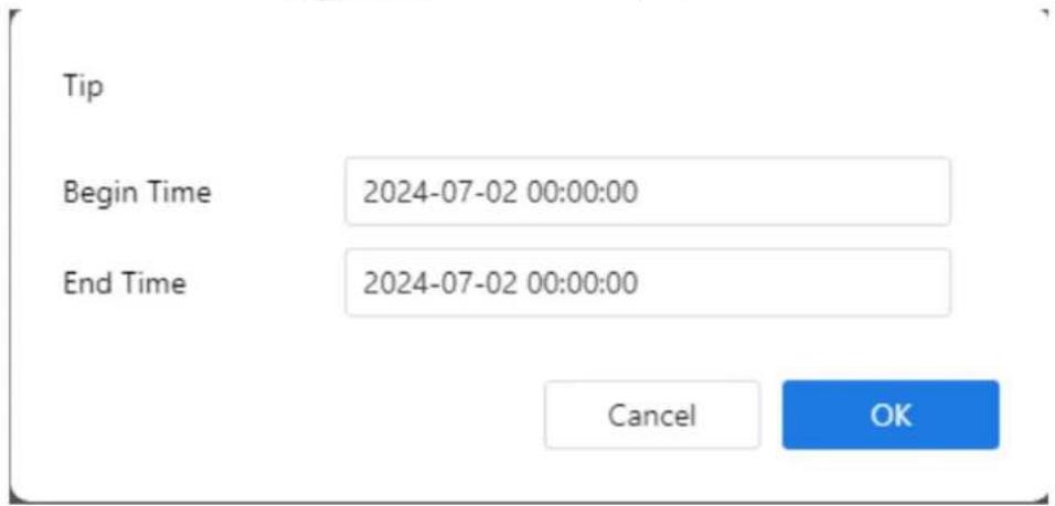
| 13 | Click to begin video backup; select the duration; click again to stop. A dialog will prompt you to save or cancel. The pop-up window of tip as shown in Figure 1-9, click the save to save the video. Click Cancel to abandon. Backup Download List Click the backup list to show the detail information. | |
| 14 | Time view options: 1h, 6h, 12h, 24h. |
Figure 1-9 Record backup tip
text_image
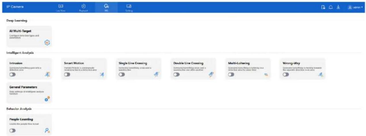
Tip Begin Time 2024-07-02 00:00:00 End Time 2024-07-02 00:00:00 Cancel OK1.5 IVS Setting
Click IVS to access the IVS configuration page. You can configure:
- Deep learning settings
• Intelligent video analytics
• Behavior analysis features
Refer to Figure 1-10 for the IVS setting layout.
D-Link F-Series Camera User Guide Quick Overview
Figure 1-10 IVS setting page
text_image
IP Camera Last Wave Refresh WS Setting Deep Learning AI Multi-Target Configure detection types and explanations Intelligent Analysis Intrusion Someone/simphicking gaps into a detection area Smart Motion Someone/Personal is considered required as the area in a detection area Single Line Crossing Someone/simphicking cross over a walking line Double Line Crossing Someone/simphicking cross over a walking line after another Multi-Loltering Someone/simphicking cross over a walking line after another Wrong-Way Someone/Simphicking is moving towards the regular direction in an area General Parameters User settings of intelligent analysis function Behavior Analysis People Counting Create the people flow input
NOTE
The IVS features vary by device model. Refer to the product specification for supported functionality.
2.1 Local Network
Description
The local network settings include the following parameters:
- IP protocol
- IP address
- Subnet mask
- Default gateway
• Dynamic Host Configuration Protocol (DHCP)
• Preferred Domain Name System (DNS) server
• Alternate DNS server
• MTU (Maximum Transmission Unit)
Procedure
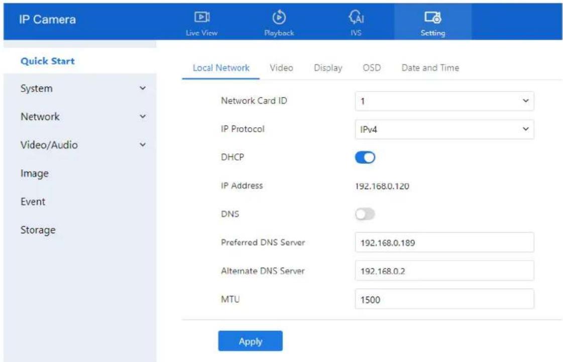
- Navigate to Setting > Quick Start > Local Network. The Local Network page is displayed (see Figure 2-1).
- Configure the parameters, as shown in Figure 2-1.
Figure 2-1 Local network page
text_image
IP Camera Live View Playback IVS Setting Quick Start Local Network Video Display OSD Data and Time System Network Classical ID 1 Network Audio IP Protocol IPv4 Image Event Storage DHCP IP Address 192.168.0.120 DNS Preferred DNS Server 192.168.0.189 Alternate DNS Server 192.168.0.2 MTU 1500 ApplyStep 2 Set the parameters according to Table 2-1.
Table 2-1 Local network parameters
| Parameter | Description | Setting |
| Network Card ID | -- | [Default value]1 |
| IP Protocol | IPv4 is the IP protocol that uses an address length of 32 bits. IPv6 is the IP protocol that uses an address length of 64 bits. | [Setting method]Select a value from the drop-down list box.[Default value]IPv4 |
| DHCP | Enable DHCP, and the device will automatically obtain the IP address from the DHCP server. | [Setting method]Click the button on to enable DHCP.NOTETo query the current IP address of the device, you must query it on the platform based on the device name. |
| IP Address | Device IP address that can be set as required. | [Setting method]Enter a value manually.[Default value]192.168.0.120 |
| Subnet Mask | DHCP is off.Subnet mask of the network adapter. | [Setting method]Enter a value manually.[Default value]255.255.255.0 |
| Default Gateway | DHCP is off.This parameter must be set if the client accesses the device through a gateway. | [Setting method]Enter a value manually.[Default value]192.168.0.1 |
| Preferred DNS Server | DNS is on.IP address of a DNS server. | [Setting method]Enter a value manually.[Default value]192.168.0.1 |
| Alternate DNS Server | DNS is on.IP address of a domain server.If the preferred DNS server is faulty, the device uses the alternate DNS server to resolve domain names. | [Setting method]Enter a value manually.[Default value]192.168.0.2 |
| MTU | Set the maximum value of network transmission data packets. | [Setting method]Enter a value manually.NOTEThe MTU value is range from 1280 to 1500, the default value is 1500, Please do not change it arbitrarily. |
D-Link F-Series Camera User Guide Quick Start Settings
Step 3 Click Apply.
- If the message "Apply success!" appears, the system saves the configuration and displays: "Set network parameter success, please login system again." Reconnect using the new IP address.
- If the message "Parameter is invalid" appears, please verify and correct the settings.
2.2 Video
Procedure
Step 1 Go to Setting > Quick Start > Video.
The Video settings page appears (see Figure 2-2).
Step 2 Configure the parameters according to Table 2-2.
Figure 2-2 Video setting page

text_image
IP Camera Live View Playback PS Setting Quick Start Local Network Video Display OSD Date and Time System Network Video/Audio Image Event Storage Stream ID 1 2 3 Name stream1 stream2 stream3 Video Encode Type H264 H264 H264 Video Encode Level Low Low Low Audio Encode Type G711_ALAW G711_ALAW G711_ALAW Resolution 2592x1944 D1 CIF Frame Rate(fps) 60 30 30 Frame Interval 60 60 60 Bit Rate Type CBR CBR VBR Bit Rate Range 4096 1500 256 (500-12000fps) (100-6000fps) (100-1500fps) Image Quality Mid Mid Mid Smart Encode ApplyStep 3 Set the parameters according to Table 2-2.
Table 2-2 Parameters of stream configuration
| Parameter | Description | Setting |
| Stream ID | The device supports up to three video streams, depending on the model:Stream 1 provides the highest video quality and performance. It is typically used for primary viewing and recording.Stream 2 offers lower resolution options, suitable for bandwidth-limited scenarios or secondary viewing.Stream 3 delivers the lowest resolution and is ideal for preview purposes or mobile access.Note: Some models support only two streams. | [Setting method]Select a value from the drop-down list box. |
| Name | Stream name.NOTEThe stream name must consist of letters, numbers, and underscores. Only these characters are supported. | [Setting method]Enter a value manually. The value cannot exceed 32 bytes.[Default value]Stream 1 |
| Video Encode Type | The video encoding type affects both image quality and the bandwidth required for streaming. The following encoding standards are supported:MJPEGMJPEG (Motion JPEG) is an intra-frame compression format. It delivers high image quality without mosaic artifacts during motion. However, it does not support inter-frame compression, resulting in larger file sizes. MJPEG consumes significant storage and bandwidth, making it unsuitable for continuous recording or long-duration video transmission. It is best suited for capturing and transmitting alarm snapshots.H.264H.264 is a widely-used inter-frame compression standard available in three profiles:Base, Main, and High.OH.264 High Profile offers the best compression efficiency but requires higher hardware decoding performance.OH.264 Main Profile balances quality and performance.OH.264 Base Profile has the lowest hardware requirements, suitable for devices with limited processing power.When using hardware decoders, select the profile according to the device's capabilities.H.265H.265 is the next-generation video compression standard, improving upon H.264 with enhanced compression efficiency, better image quality, and more sophisticated algorithms. It significantly reduces bandwidth and storage usage while maintaining high visual fidelity, making it ideal for high-resolution and long-duration recording scenarios. | [Setting method]Select a value from the drop-down list box.[Default value]H.264 High ProfileNOTEH.264 High Profile requires higher hardware decoding capability. Use Main or Base Profile for low-performance devices.Using MJPEG in Stream 1 may result in playback issues or FTP video upload errors. |
| Audio Encode Type | The following audio encode standards are supported:☐G711_ULAW: mainly used in North America and Japan.☐G711_ALAW: mainly used in Europe and other areas.☐RAW_PCM: encode of the original audio data.This encode is often used for platform data. | [Setting method]Select a value from the drop-down list box. |
| Resolution | A higher resolution means better image quality.NOTEIP cameras support different resolutions based on the model. | [Setting method]Select a value from the drop-down list box. |
| Frame Rate(fps) | Frame rate is the number of images, snapshots, or frames that a camera can take per second. The frames per second determine the smoothness of a video. A video whose frame rate is higher than 22.5 f/s is considered as smooth by human eyes.Frame rates for different frequencies are as follows:☐50 Hz: 1–25 f/s☐60 Hz: 1–30 f/sNOTEThe frequency is set on theDeviceConfiguration >Camerapage. The biggest MJPEG coding format frame rate is 12 frames per second. | [Setting method]Select a value from the drop-down list |
| I Frame Interval(f) | I frame do not require other frames to decode.A smaller I frame interval means better video quality but higher bandwidth. | [Setting method]Select a value from the drop-down list |
| Bit Rate Type | The bit rate is the number of bits transmitted per unit of time.The following bit rate types are supported:☐ Constant bit rate (CBR)The compression speed is fast; however, improper bit rate may cause vague motion images.☐ Variable bit rate (VBR)The bit rate changes according to the image complexity. The encoding efficiency is high and the definition of motion images can be ensured. | [Setting method]Select a value from the drop-down list box. |
| Bit Rate Range | Indicates the maximal value of the bit rate. the different models may have different ranges, please refer to actual product. | [Setting method]Enter a value manually. |
| Image Quality | The video quality the camera output. | [Setting method]Select a value from the drop-down list box. |
| Smart Encode | Smart Encode.☐Smart encode includes H.264 & H.265.☐The storage space will be reduced fifty percent when smart encode is enabled.☐Only main stream supports smart encode. | [Setting method]Click the button on to enableSmart Encode. |
Step 4 Click Apply.
• If you see "Apply success!", the settings are saved.
- If "Apply failed!" appears, ensure you have Parameter Configure permissions (see Section 3.3 Configure User).
• If a bit rate error is shown, enter a valid bit rate value.
2.3 Display
2.3.1 Access the Display Settings
Procedure:
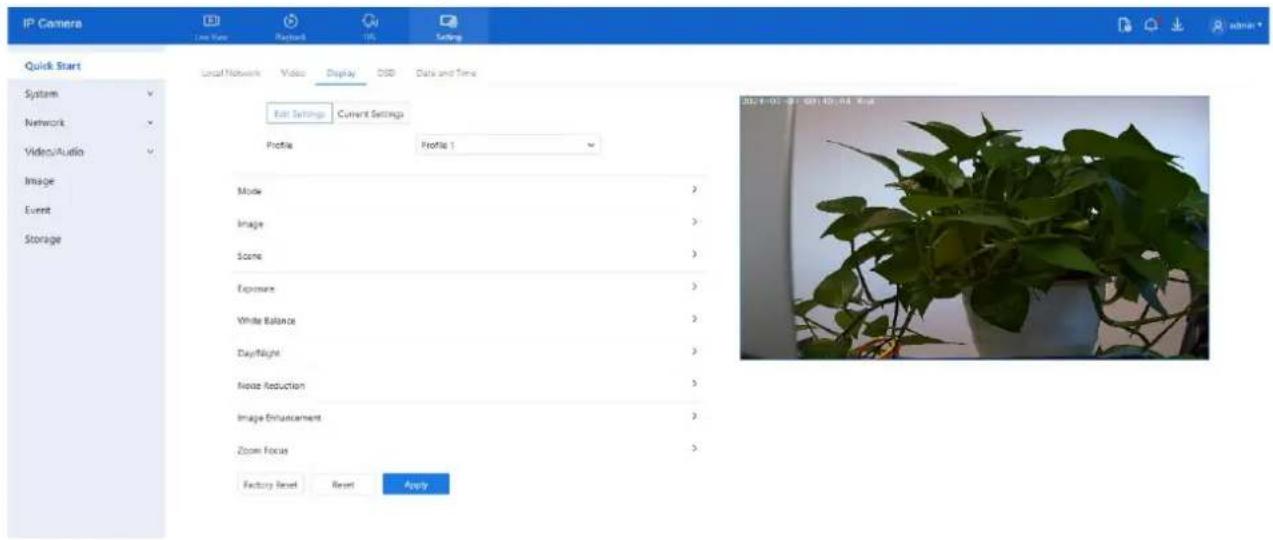
Step 1 Navigate to Setting > Quick Start > Display. The Image Settings page appears.
Figure 2-3 Image settings page
text_image
IP Camera Local Network Video Display GSD Data and Time Quick Start System Network Video/Audio Image Event Storage Local Network Video Display GSD Data and Time Edit Settings Current Settings Profile Profile 1 Mode 3 Image 3 Scene 3 Exposure 3 White Balance 3 Daylight 3 Noise Reduction 3 Image Enhancement 3 Zoom Focus 3 Factory Reset Reset Apply 20:14:00, 25:07:00, 08:00:00 EndStep 2 Click Edit Settings under the Mode item to configure display profiles. Up to four profiles can be set.

NOTE
● All image settings can be modified in Edit Settings.
● Factory Reset restores all parameters to factory defaults.
- Reset reverts settings to the last saved state..
2.3.2 Mode
Procedure:
Step 1 Go to Setting > Quick Start > Display > Mode. The Mode page appears, as shown in Figure 2-4.
Figure 2-4 Mode page

text_image
Mode Switch Mode None Start Time 00 : 00 End Time 24 : 00Step 2 Click Switch Mode. Three options are available:
• None: Uses the current active profile with no switching.
- Time Mode: Automatically switches profiles at specific times. Set all four profiles in advance.
- Day/Night (D/N) Linkage Mode: Automatically switches between day and night profiles based on lighting.
Step 3 Set the Start Time and End Time for switching. Step 4 Click Apply to save your settings.
2.3.3 Image Setting
Procedure:
Step 1 Navigate to Setting > Quick Start > Display > Image. The Image Settings page appears as shown in Figure 2-5.
Figure 2-5 Image setting page

text_image
Image Brightness - + 50 Saturation - + 50 Contrast - + 50 Sharpness - + 50Table 2-3 Describes the image setting parameters.
Table 2-3 Parameters of image settings parameters
| Parameter | Description | Configuration Method |
| Brightness | Controls image brightness. | [Setting method]Drag the slider.[Default value]50 |
D-Link F-Series Camera User Guide Quick Start Settings
| Parameter | Description | Configuration Method |
| Saturation | Controls image color richness. | [Setting method]Drag the slider.[Default value]50 |
| Sharpness | Controls image clarity. | [Setting method]Drag the slider.[Default value]50 |
| Contrast | Adjusts contrast between dark and bright areas. | [Setting method]Drag the slider.[Default value]50 |
Step 2 Click Apply to save your settings.
2.3.4 Scene Mode
Procedure:
Step 1 Go to Setting > Quick Start > Display > Scene Step 2 The Scene Mode page appears as shown in Figure 2-6.
Figure 2-6 Scene mode page

text_image
Scene Scene Outdoor Mirror Normal Corridor Mode Tip: Please Update Motion Detection, Privacy Mask, Intelligent Analysis, ROI and OSD Area Settings After [Corridor Mode]/[Mirror] was Changed.Table 2-4 describes the FFC mode parameters.
Table 2-4 Parameters of FFC
| Parameter | Description | Configuration Method |
| Scene | It indicates the working mode of camera.☐ Outdoor: Suitable for outdoor use.☐ Indoor: Suitable for indoor use. | [Configuration method]Select from the drop-down list [Default value]Outdoor |
D-Link F-Series Camera User Guide Quick Start Settings
| Parameter | Description | Configuration Method |
| Mirror | It is used to select the pixel location of an image. □ Normal: The image does not flip. □ Horizontal: The image flips to the left and right. □ Vertical: The image flips up and down. □ Horizontal and vertical: The image rotates at 180° degrees. | [Setting method]Select a value from the drop-down list.[Default value]Normal |
| Corridor Mode | The image rotates 90° degrees clockwise when aisle mode is enabled. On some models, using Stream 2/3 with H.264/H.265 at CIF or QVGA resolution may prevent live view playback. | [Setting method]Tick the corridor mode.[Default value]Disable |
Step 3 Click Apply to save the setting.
2.3.5 Exposure
Procedure:
Step 1 Navigate to Setting > Quick Start > Display > Exposure.
The Exposure page appears (see Figures 2-7 and 2-8 for IP cameras and high-speed domes, respectively).
Step 2 Configure the parameters listed in Table 2-5.
Figure 2-7 Exposure interface for IP camera

text_image
Exposure Metering Mode Full Metering Exposure Mode Auto Max Shutter 1/60 Max Gain - + 50Figure 2-8 Exposure Interface for high-speed home
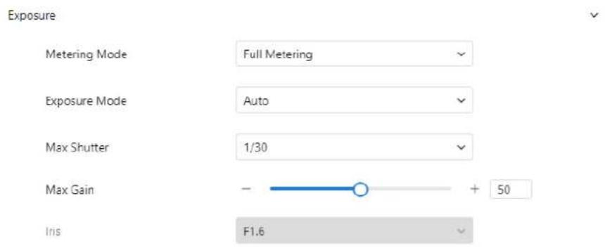
text_image
Exposure Metering Mode Full Metering Exposure Mode Auto Max Shutter 1/30 Max Gain - + 50 Iris F1.6Table 2-5 describes Exposure parameters.
Table 2-5 Parameters of exposure
| Parameter | Meaning | Configuration Method |
| Exposure Mode | The exposure modes include:Auto: The system performs auto exposure based on the monitoring environment.Manual: You can adjust the brightness of an image by setting the following three items:Shutter Setting, Iris Setting and Gain Setting.Shutter Priority: You can set Shutter Setting to fixed values. The iris and gain are automatically adjusted by the system.Iris Priority (for high-speed dome):You can set Iris Setting to fixed values. The shutter and gain arc automatically adjusted by the system. | [Setting method]Select a value from the drop-down list.[Default value]Auto |
| Meter Mode | It is used to select the metering area.Fulling Metering: During metering, all areas of an image have equal weight, that is, all areas are involved in the metering.Spot Metering: During metering, the central spot of an image has the highest weight.Partial Metering: During metering, the middle area (1/2 of the total area) of an image has the highest weight, and other areas have the lowest weight. | [Setting method]Select a value from the drop-down list.[Default value]Whole |
| Max Shutter | The device automatically adjusts the shutter time based on the ambient brightness. The shutter time is less than or equal to the value of this parameter. | [Setting method]Select a value from the drop-down list.[Default value]1/25 |
| Max Gain | The device automatically adjusts the gain based on the external light. The gain is less than or equal to the value of this parameter. | [Setting method]Drag the slider.[Default value]50 |
| Iris (for high speed dome) | It is valid in manual mode and iris priority mode. You can adjust the brightness of an image by setting the iris. As the value increases, the brightness increases (when the shutter and gain remain the same). However, the camera movement automatically adjusts the shutter and gain in this mode. Therefore, the brightness of an image may not increase when you increase the iris. | [Setting method]Select a value from the drop-down list.[Default value]F1.6 |
D-Link F-Series Camera User Guide Quick Start Settings
| Parameter | Meaning | Configuration Method |
| Iris (for IP camera) | It is used to control the light admitted to the lens.The auto iris can be set to either of the following states:AutoThe iris is automatically adjusted to control the light admitted to the lens.Open fullyThe iris is fully open. | [Setting method]Select a value from the drop-down list.[Default value]Auto |
| Iris Speed | It indicates the auto adjustment speed of the iris. As the value increases, the speed increases. Excessive speed may cause instability.NOTEThis parameter is valid when the auto iris is enabled. | [Setting method]Drag the slider.[Default value]50 |
| Fixed Gain | When the exposure Mode is Manual, you can set the fixed gain. | [Setting method]Drag the slider.[Default value]50 |
Step 3 Click Apply to save the setting.
2.3.6 White Balance Setting
Procedure:
Step 1 Navigate to Setting > Quick Start > Display > White Balance. The White Balance page appears as shown in Figure 2-9.
Figure 2-9 White balance settings page

text_image
White Balance Mode Auto Red Gain - ○ + 0 Blue Gain - ○ + 0D-Link F-Series Camera User Guide
Quick Start Settings
Table 2-6 White Balance (WB) Parameters
| Parameter | Meaning | Configuration Method |
| Mode | Select a white balance mode to improve color accuracy based on lighting conditions:Auto: The system automatically adjusts based on the environment.Tungsten: For incandescent lighting.Fluorescent: For fluorescent lighting.Daylight: For natural sunlight.Shadow: For shaded areas.Manual: Manually configure WB mode based on the monitoring environment. | [Setting method]Select a value from the drop-down list.[Default value]Auto |
| Red Gain | Adjusts the intensity of red tones. Increasing this value lowers the color temperature.NOTEAvailable only inManual ModewithCustomized selected. | [Setting method]Drag the slider.[Default value]0 |
| Blue Gain | Adjust the intensity of blue tones. Increasing this value raises the color temperature (image becomes cooler).NOTEAvailable only inManual ModewithCustomized selected. | [Setting method]Drag the slider.[Default value]0 |
Step 2 Click Apply to save the setting.
2.3.7 Day/Night
Procedure:
Step 1 Navigate to Setting > Quick Start > Display > Day/Night.
The Day/Night settings page appears. Display options may vary by device model (see Figure 2-10).
D-Link F-Series Camera User Guide Quick Start Settings
Figure 2-10 Day/Night page (timer)
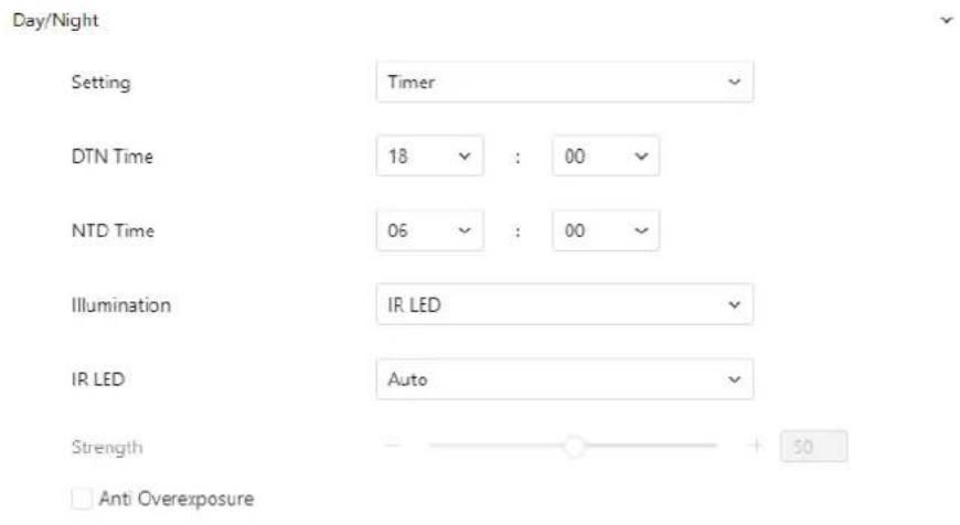
text_image
Day/Night Setting Timer DTN Time 18 : 00 NTD Time 06 : 00 Illumination IR LED IR LED Auto Strength + 50 Anti OverexposureFigure 2-11 Day/Night mode page (auto)
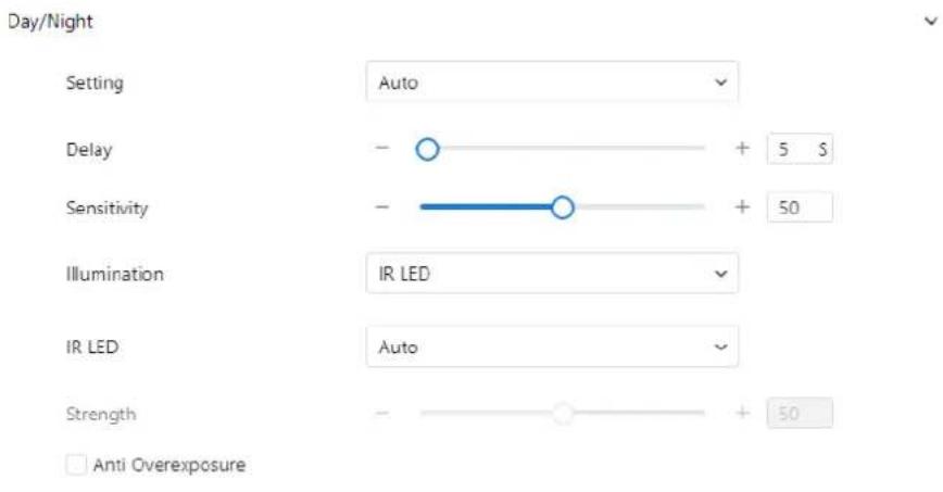
text_image
Day/Night Setting Auto Delay - + 5 S Sensitivity - + 50 Illumination IR LED IR LED Auto Strength - + 50 Anti OverexposureStep 2 Configure the parameters listed in Table 2-7.
Table 2-7 Parameters of Day/Night
| Parameter | Meaning | Configuration Method |
| D/N Setting Mode | It can be set toAuto, Day, Night or Timer.□ Auto modeThe image color and filter status automatically switch based on the ambient brightness. The filter keeps infrared light from reaching the sensor during the day; The filter allows all light to reach the sensor at night.□ Day modeForces the camera to stay incolor mode.The IR filter remains active, blocking infrared light from reaching the sensor.□ Night modeForces the camera to display inblack and white. The IR filter is disabled, allowing infrared light to reach the sensor for better night vision.□ TimerAutomatically switches between Day and Night modes based on a user-defined schedule. | [Setting method]Select a value from the drop-down list.[Default value]Auto |
| D/N Switch Sensitivity | Adjusts the sensitivity of day-to-night switching. A higher value causes the system to switch at lower light levels.NOTEThis parameter is valid in auto mode. | [Setting method]Drag the slider.[Default value]50 |
| TRANSI.(D->N) (dB) | High-Speed DomeGain threshold for switching from Day to Night in Auto mode. The system enters Night mode when gain exceeds this value.NOTEThis parameter is valid in auto mode. The value ofTRANSI.(D->N) must be greater than the value ofTRANSI.(N->D). | [Setting method]Drag the slider.[Default value]70 |
| TRANSI.(N->D) (dB) | High-speed DomeGain threshold for switching from Night to Day. The system enters Day mode when gain drops below this value.NOTEThis parameter is valid in auto mode. The value ofTRANSI.(D->N) must be greater than the value ofTRANSI.(N->D). | [Setting method]Drag the slider.[Default value]30 |
| Delay(s) | Delay time (in seconds) for switching between Day and Night.NOTEThis parameter is valid in auto mode. | [Setting method]Drag the slider.[Default value]0 |
| Light Mode | Specifies the lighting mode based on the camera model:IR LEDWhite LEDIntelligent Dual Light (uses IR and White LED based on condition)None | [Setting method]Select a value from the drop-down list. |
| IR LED | Auto: The infrared lamp is enabled or disabled based on the external environment identified by the light dependent resistor (LDR).ON: The system enters the night mode forcibly.OFF: The infrared lamp is disabled. The filter and image color are switched based on the external environment identified by the LDR.NOTEThis parameter is valid in auto mode. | [Setting method]Select a value from the drop-down list.[Default value]Auto |
| Strength | Controls IR LED brightness. Higher values produce brighter night images. | [Setting method]Drag the slider.[Default value]50 |
| DTN Time | Time to switch from Day to Night. | [Setting method]Select a value from the drop-down list.[Default value]18:00 |
| NTD Time | Time to switch from Night to Day. | [Setting method]Select a value from the drop-down list.[Default value]6:00 |
Fill light settings
The camera's fill light supports four modes:
- Intelligent Dual Light – Automatically switches from IR to white light during alarms, then reverts after 30 seconds.
- Warm Light – Uses only white light for nighttime illumination.
- Infrared Lamp – Uses IR light only.
- Close - Disables the fill light. The image remains in the last active mode.
Modes of Operation
- Day Mode: Used in well-lit environments where the image remains in color. No fill light is needed.
• Night Mode: Used in low-light environments with the fill light enabled.
• Auto Mode: Automatically adjusts the fill light based on ambient lighting. - Timer Mode: Allows you to define the active time for Day mode.
Brightness Adjustment
• Automatic Mode: Adjusts fill light brightness automatically based on environment.
- Manual Mode: You can manually set the brightness using the slider or input value.
2.3.8 Noise Reduction
Procedure:
Step 1 Go to Setting > Quick Start > Display > Noise Reduction.
Step 2 The Noise Reduction interface will appear (see Figure 2-12).
There are two modes available for noise reduction: Auto and Manual.
- Auto Mode: The system automatically adjusts noise reduction levels based on ambient conditions.
- Manual Mode: You can set a fixed level of noise reduction.
Figure 2-12 Noise reduction page (auto)
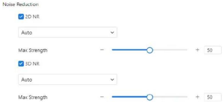
text_image
Noise Reduction ✓ 2D NR Auto Max Strength - + 50 ✓ 3D NR Auto Max Strength - + 50Figure 2-13 Noise reduction page (manual)
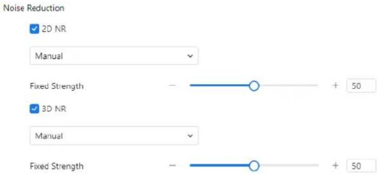
text_image
Noise Reduction ✓ 2D NR Manual Fixed Strength - + 50 ✓ 3D NR Manual Fixed Strength - + 50Table 2-8 describes the Noise Reduction parameters.
Table 2-8 Parameters of noise reduction
| Parameter | Meaning | Configuration Method |
| 2D NR | Reduces noise of image. | [Configuration method]Select from the drop-down list [Default value]Auto |
| 3D NR | Reduces noise of image. | [Configuration method]Select from the drop-down list [Default value]Auto |
| Max Strength | Applicable only in auto noise filter mode.When set to 0, noise reduction is disabled.When set above 0, the system automatically adjusts the noise reduction level based on ambient brightness, but will not exceed the configured value. | [Setting method]Drag the slider.[Default value]50 |
| Fixed Strength | Applicable only in manual noise filter mode. | [Setting method]Drag the slider.[Default value]50 |
Step 3 Click Apply to save the setting.
2.3.9 Image Enhancement
Procedure:
Step 1 Go to Setting > Quick Start > Display > Image Enhancement. Step 2 Adjust the parameters listed in Table 2-9.
Figure 2-14 Image Enhancement page

text_image
Image Enhancement □ WDR - + 50 □ HLC - + 50 □ BLC - + 50 □ Defog - + 50Table 2-9 Parameters of enhance image
| Parameter | Meaning | Configuration Method |
| WDR | Enhances image quality in scenes with strong lighting contrast background. When brightness contrast is high, increasing the both bright and dark areas. | [Setting method]Tick the WDR mode and drag the slider.[Default value]50 |
| HLC | Reduces the intensity of overly bright areas to improve visibility of objects in front of light sources (e.g., headlights). Reduces total brightness to enhance clarity of highlighted regions. | [Setting method]Tick the HLC mode and drag the slider.[Default value]50 |
| BLC | Increases overall brightness to make objects in front of backlit scenes more visible. May cause overexposure of the background. | [Setting method]Tick the BLC mode and drag the slider.[Default value]50 |
| Anti-shake | Reduces slight shaking or jitter in the image caused by minor camera movement. | [Setting method]Tick the Anti-shake mode. |
| DeFog | Enhances image clarity in foggy or hazy environments.Higher values increase visibility.Note: Available only on some models. | [Setting method]Tick the Defog mode and drag the slider.[Default value]50 |
Step 3 Click Apply to save the settings.
2.3.10 Zoom Focus (Only for Some Models)
Procedure:
Step 1 Navigate to Setting > Quick Start > Display > Zoom Focus.
The Zoom Focus interface appears (see Figure 2-15 for IP cameras and Figure 2-16 for high-speed domes).
Step 2 Configure the parameters listed in Table 2-10.
D-Link F-Series Camera User Guide Quick Start Settings
Figure 2-15 Zoom focus page for IP camera 1

text_image
Zoom Focus [+]Auto Focus Once Lens Initialization D/N Auto Focus Factory Reset Reset ApplyFigure 2-16 Zoom focus interface for high speed dome
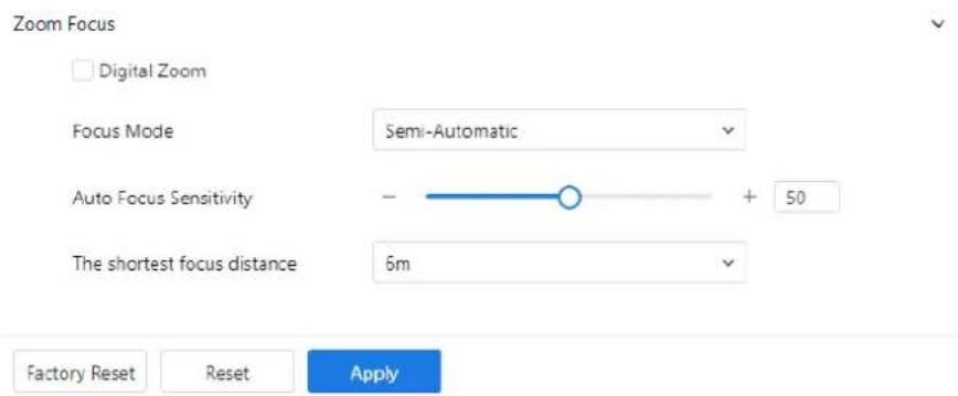
text_image
Zoom Focus Digital Zoom Focus Mode Semi-Automatic Auto Focus Sensitivity - + 50 The shortest focus distance 6m Factory Reset Reset ApplyTable 2-10 Parameters of zoom focus
| Parameter | Meaning | Configuration Method |
| D/N Auto Focus | Enables auto focus when switching between Day and Night modes. | [Setting method]Tick the Auto focus. |
| Auto Focus Once | Triggers auto focus one time. | [Setting method]Click the button. |
| Initial | Returns the camera lens to its initial position. | [Setting method]Click the button. |
| Digital | Enables digital zoom after 37x optical zoom is reached. | [Setting method]Tick the Digital. |
| Focus Mode | Sets the focus mode:Auto: System automatically adjusts focus based on the scene.Manual: User manually adjusts focus using on-screen controls.Semi-Automatic: Auto focus is triggered once when the PTZ moves or zooms in. | [Configuration method]Select from the drop-down list [Default value]Semi-automatic |
| Auto Focus Sensitivity | Controls how easily the system re-focuses when changes occur in the image.Higher sensitivity means the camera will re-focus with minor scene changes. | [Setting method]Drag the slider.[Default value]50 |
| The Least Focus Distance | Defines the minimum distance at which the camera can focus.If the object is closer than this distance, the camera will not focus on it.Example: If set to 1.5 meters, objects must be more than 1.5 meters away to be in focus.NOTEApplicable only to visible light. | [Configuration method]Select from the drop-down list [Default value]3 m |
Step 3 Click Apply to save the settings.
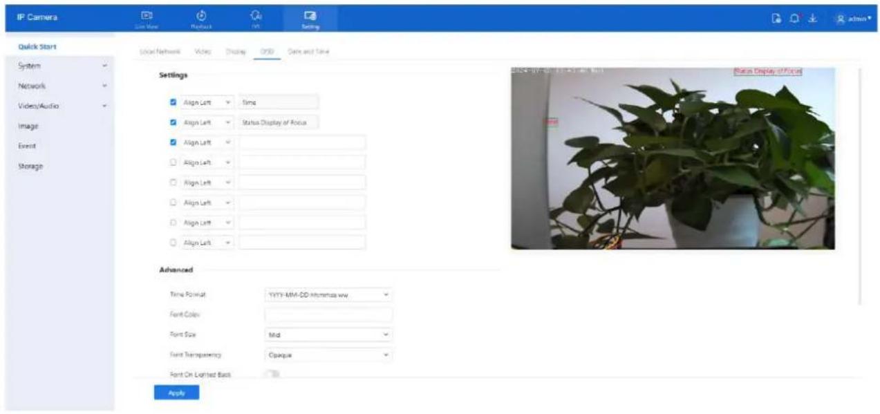
2.4 OSD
Description
The On-Screen Display (OSD) function allows you to overlay information on video streams, including:
- Device name
• Channel ID and name - Time
- Customized content
You can drag and reposition OSD elements on the screen.
Note: When the resolution is set to D1 or CIF, OSD supports up to 22 characters. OSD supports Simplified Chinese, English, numbers, and select special characters.
Procedure
Step 1 Go to Setting > Quick Start > OSD.
The OSD page is displayed (see Figure 2-17).
Step 2 Configure the parameters listed in Table 2-11.
D-Link F-Series Camera User Guide Quick Start Settings
Figure 2-17 OSD (standard cameras)
text_image
IP Camera Quick Start System Network Video/Audio Image Event Storage Local Network Video Display QRS Data and Time Settings Align Left Time Align Left Status Display of Focus Align Left Align Left Align Left Align Left Align Left Align Left Align Left Advanced Time Format: YYYY-MM-DD Mimming ww. Font Colors: Font Size: Mid Font Transparency: Opaque Font On Labeled Back Apply Status Display of Focus
NOTE
Up to seven OSD display areas can be configured.
Table 2-11 Parameters of OSD
| Parameter | Description | Setting |
| Time | Enables display of the system time. | [Setting method]Tick the time. |
| Focusing on the State | Displays focusing status.NOTE:Available only for cameras with auto-focus lenses. | [Setting method]Tick the Focusing on the state. |
| Custom OSD | Allows you to add a custom line of text. | [Setting method]1. Tick the custom OSD list.2. Enter the characters.Click to save the value. |
| Time Format | Defines the display format of the time. | [Setting method]Select a value from the drop-down list box.[Default value]YYYY-MM-DDhh:mm:ss ww |
| Font Color | Sets the color of the displayed text. | [Setting method]Select a value from the drop-down list box.[Default value]Blank |
| Font Size | Sets the size of the text. | [Setting method]Select a value from the drop-down list box.[Default value]Mid |
| Font Transparency | Controls the transparency of the OSD text. | [Setting method]Select a value from the drop-down list box.[Default value]Opaque |
| Font on Lighted Back | Enables background lighting for better text visibility. | [Setting method]Click the button on to enable Font on lighted back. |
| Device Name | Displays the device name in the video. | [Setting method]Click the button on to enable Device Name |
| PTZ Position | Only used for PTZ cameras | [Setting method]Click the button on to enable |
| PTZ Action | [Setting method]Click the button on to enable | |
| PTZ Temperature | [Setting method]Click the button on to enable | |
| Status Display of Focus | Shows live focusing status on screen. | [Setting method]Click the button on to enable |
| Twelve-hour System | Enables 12-hour clock format. | [Setting method]Click the button on to enable |
D-Link F-Series Camera User Guide Quick Start Settings
| Parameter | Description | Setting |
| Display Week | Enables display of the current weekday. | [Setting method]Click the button on to enable |
Step 3 Click Advanced to configure additional options such as:
- Time Format
- Font Color
- Font Transparency
- Font Background
Step 4 Click Apply.
The message "Apply success!" confirms that the settings have been saved.
2.5 Date and Time
Description
The Date and Time page allows you to configure the system's date, time, and synchronization settings. The following parameters can be adjusted:
• Time zone and Daylight Saving Time (DST)
- Date and time (manual or synchronized)
• Network Time Protocol (NTP) server settings
Procedure
Step 1 Go to Setting > Quick Start > Date and Time.
The Date and Time page appears, as shown in Figure 2-18.
Step 2 Configure the parameters listed in Table 2-12.
Figure 2-18 Date and time page

text_image
IP Camera Live View Playback IVS Setting Quick Start Local Network Video Display OSD Date and Time System Time Zone (GMT) Greenwich Mean Time : Dublin, Edinburgh, Lisbon, London Network Device Time 2024-07-03 13:55:10 Video/Audio Image Set Manually 2024-07-03 13:52:58 Event NTP Synchronize with PC time Storage Daylight Savings Time ApplyTable 2-12 Parameters of date and time
| Parameter | Description | Setting |
| Time Zone | Sets the time zone of the device. N/A | [Setting method]Select a value from the drop-down list box.[Default value]Greenwich mean time |
| Device Time | Displays the current time on the device. | [Setting method]☐ Synchronize the time from the PC.Enter a value manually. |
| Set Manually | You can set the device time manually or synchronize with PC time. | [Setting method]Click Set Manually and set the date and time in the format YYYY-MM-DD HH:MM: SS. |
| NTP | IP address or domain name of the NTP server. | [Setting method]Click the button on to enable NTP and enter a value manually. |
| Server Address | NTP is enabled.The NTP server IP. | [Setting method]Enter a value manually. |
| Port | NTP is enabled.Port number of the NTP server. | [Setting method]Enter a value manually.[Default value]123 |
| Interval | NTP is enabled.Set time interval to check if the device time has synchronized with the NTP server time. | [Setting method]Enter a value manually.[Default value]60 |
| Daylight Saving Time | Adjusts the device time for DST:When DST starts, the device time is moved forward by one hour.When DST ends, the device time is moved back by one hour. | [Setting method]Click the button on to enable Daylight Saving Time. |
Step 3 Click Apply to save the settings. If the message "Apply success!" appears, the settings have been saved successfully.
3 System Settings
3.4 Settings
3.4.1 Device Information
Description
The Device Information page displays the following system details:
• Device ID, name, type, model, manufacturer name, and MAC address
• Hardware version and software version
- Video channel count, alarm input/output channel count, serial port count, and number of network cards

NOTE
• The device name is the only editable field.
- All other parameters are view-only.
• Device information updates automatically after a software upgrade
Procedure
Step 1 Go to Setting > System > Settings > Device Info. The Device Info page is displayed, as shown in Figure 3-1.
Figure 3-1 Device info page
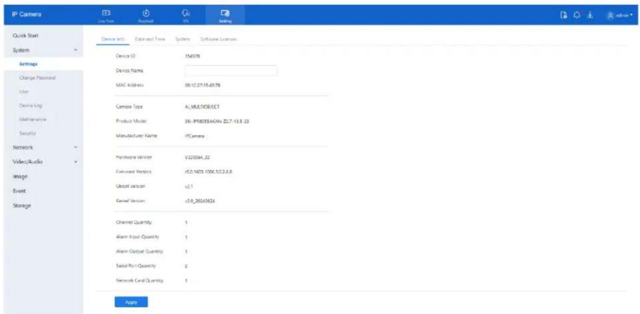
text_image
IP Camera Quick Start System Settings Change Password User Device Log Maintenance Security Network Video/Audio Image Event Storage Device Info Data and Time System Software Licenses Device ID 154378 Device Name MAC Address 00-IC27-15.49.78 Camera Type AL_MULTIOBJECT Product Model SN-IPR0056AKAN-Z2.7-13.8-23 Manufacturer Name IPCamera Hardware Version V2200H_22 Firmware Version V5.0-M23-1006.3.0.2.6.8 Uboot Version v2.1 Kernel Version v3.0-20340624 Channel Quantity 1 Alarm Input Quantity 1 Alarm Output Quantity 1 Serial Port Quantity 0 Network Cord Quantity 1 ApplyStep 2 View the system information and set the Device Name as needed, according to Table 3-1.
D-Link F-Series Camera User Guide
System Settings
Table 3-1 Parameters of device
| Parameter | Description | Setting |
| Device ID | A unique identifier used for platform management. | [Setting method]The parameter cannot be modified. |
| QR Code | The code and code characters.NOTEAvailable on some models. | Click the icon to enlarge the code. |
| P2P | Enables peer-to-peer (P2P) connection. When the device's P2P status is "Online", users can manage it via mobile apps.NOTEAvailable on some models. | [Setting method]Enable |
| Device Name | The name used to identify the device.NOTEMaximum length is 32 bytes or 10Simplified Chinese characters.Modification fails if exceeded. | [Setting method]Enter a value manually. |
| MAC Address | It shows the performance of camera | [Setting method]These parameters cannot be modified. |
| Camera Type | ||
| Product Model | ||
| Manufacturer Name | ||
| Hardware Version | ||
| Firmware Version | ||
| Uboot version | ||
| Kernel version | ||
| Video Channel(s) | ||
| Channel Quantity | ||
| Alarm Input Quantity | ||
| Alarm Output Quantity | ||
| Serial Port Quantity | ||
| Network card Quantity |
Step 3 Click Apply.
- If the message "Apply success!" appears, the settings have been saved.
- If "Apply failed!" appears, you must request Parameter Configure permissions from an administrator.
3.4.2 Date and Time
The detailed information, please refer to Chapter 2.5
3.4.3 System
Procedure:
Step 1 Go to Setting > System > Settings > System.
The System page is displayed (see Figure 3-2).
Step 2 Choose the language from the drop-down list.
Figure 3-2 System
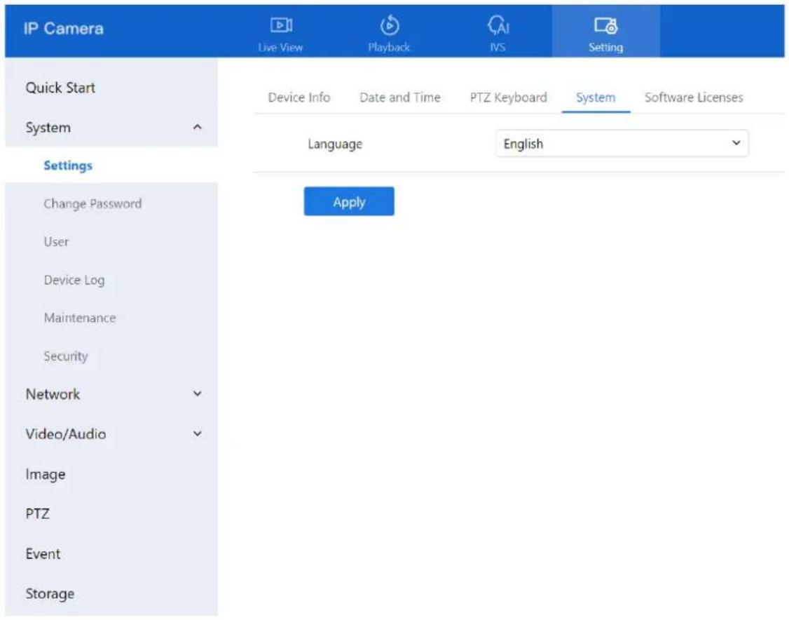
text_image
IP Camera Live View Playback IVS Setting Quick Start Device Info Date and Time PTZ Keyboard System Software Licenses System Language English Settings Change Password Apply User Device Log Maintenance Security Network Video/Audio Image PTZ Event Storage3.4.4 Software Licenses
Procedure
Step 1 Go to Setting > System > Settings > Software Licenses. The Software Licenses page is displayed, as shown in Figure 3-3.
Figure 3-3 Software licenses page

text_image
IP Camera Live View Playback IVS Setting Quick Start Device Info: Date and Time System Software Licenses System Open Source Software Licens... View Licenses Settings Change Password User Device Log Maintenance Security Network Video/Audio Image Event StorageStep 2 Click View Licenses to display the list of open-source software licenses used in the system.
3.5 Change Password
1.2 For detailed information, please refer to Chapter 1.2.
3.6 Configure User
3.6.1 Add User
Description
This function allows you to add, modify, or delete users in the Privilege Manager section.
Procedure
Step 1 Navigate to Setting > System > User. The User page is displayed, as shown in Figure 3-4. Table 3-2 describes the parameters.
D-Link F-Series Camera User Guide System Settings
Figure 3-4 User page

text_image
IP Camera Live View Playback INS Setting Quick Start User Online User System Add Settings Change Password ID User Name Groups Description Operate 1 admin SuperAdmin admin Device Log Maintenance Security Network Video/Audio Image Event StorageStep 2 Add, modify, or delete users as needed.
Table 3-2 Parameters of user
| Parameter | Description | Setting |
| ID | User ID | User ID (not configurable). |
| User Name | Name used to log in to the camera. | [Setting method]Select a value from the drop-down list box. |
| Groups | Specifies the user group. Default groups include:Super Admin: Full access to all system featuresAdministrators: Access to live video, playback, PTZ, audio, system, log, record policies, disk config, privilege, and parameter settingsOperator: Access to live video, playback, PTZ, parameter config, and maintenanceMedia User: Live video only | [Setting method]Click Add, then select a value from the drop-down list box. |
D-Link F-Series Camera User Guide System Settings
| Parameter | Description | Setting |
| Notes | Optional notes for the user. | [Setting method]Click Add, then enter a value manually. |
| Operate | Actions include view, modify, and delete.NOTESuper Admin can be viewed only. | [Setting method]Click the icon as required. |
Table 3-3 Operation description
| Function | Procedure | Description |
| Add | 1. Click Add.The Add User page is displayed, as shown in Figure 3-5.2. Enter a user name, password, confirm password.3. Select a group from the drop-down list box.4. Enter the notes (Optional).5. Check the privilege.6. Click OK.The user is added successfully. | Add an administrator or a common user as shown in Figure 3-5. |
| Modify | 1. Click .The Modify User page is displayed.2. Modify the user name, password, group or privilege.3. Click OK.The user is modified successfully. The User page is displayed. | Modify the user name, password, group or privilege. |
| Delete | Click theicon.When prompted with "Confirm to delete?", click OK | Deletes a user. |
D-Link F-Series Camera User Guide System Settings
Figure 3-5 Add user page
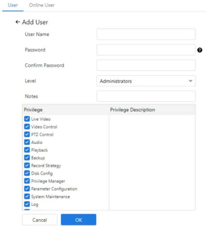
text_image
User Online User ← Add User User Name Password Confirm Password Level Administrators Notes Privilege Privilege Description Live Video Video Control PTZ Control Audio Playback Backup Record Strategy Disk Config Privilege Manager Parameter Configuration System Maintenance Log Cancel OK
NOTE
Click the privilege list to view a detailed breakdown of functions associated with each user group.
3.6.2 Online User
Procedure
Step 1 Navigate to Setting > System > User > Online User. The Online User page is displayed, as shown in Figure 3-6.
Step 2 View all users currently connected to the system in real time.
D-Link F-Series Camera User Guide System Settings
Figure 3-6 Online user
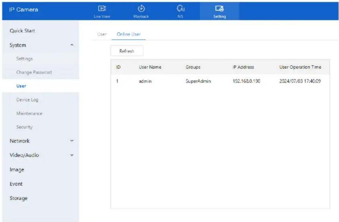
text_image
IP Camera Live View Playback IVS Setting Quick Start User Online User System Settings Change Password Refresh ID User Name Groups IP Address User Operation Time 1 admin SuperAdmin 192.168.0.190 2024/07/03 17:40:09 Device Log Maintenance Security Network Video/Audio Image Event Storage3.7 Query Device Logs
3.7.1 Query Operation Logs
Description
The operation log records user actions and scheduled task instructions during device operation. These logs are categorized as follows:
- Privilege manager
- System maintenance
- Device operations
- Recording operations
- Video control
- Live video
Procedure
Step 1 Navigate to Setting > System > Device Log > Operation Log. The Operation Log page appears, as shown in Figure 3-7.
D-Link F-Series Camera User Guide System Settings
Figure 3-7 Operation log page

text_image
IP Camera Live View Playback IVS Setting Quick Start System Settings Change Password User Device Log Maintenance Security Network Video/Audio Image Event Storage Operation Log Alarm Log Collect All Logs Operation Log All Types Start Time 2024-07-02 17:58:54 End Time 2024-07-03 17:58:54 Download Search Time User Name Log InfoStep 2 Set the query conditions.
- Select the type of operation logs from the Operation Log drop-down list.
- Click the Begin Time and End Time text boxes to display the time selection panel, and set the desired time range.
- Select the username from the User Name drop-down list.
Step 3 Click Search. The logs matching the specified criteria are displayed.
Download the operation logs.
To download logs:
Step 1 Select the log type.
Step 2 Set the start time, end time, and log type.
Step 3 Click Download.
Step 4 The log Excel file will be saved automatically to the browser's default download path.
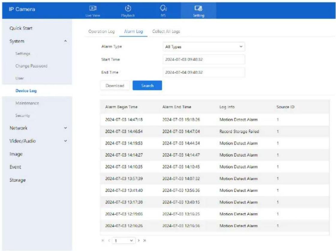
3.7.2 Query Alarm Logs
Description
Alarm logs capture events triggered by system alerts, including:
- Security alarms
- Disk alarms
D-Link F-Series Camera User Guide System Settings
- Recording alarms
• Intelligent analysis alarms
Procedure
Step 1 Navigate to Setting > System > Device Log > Alarm Log. The Alarm Log page appears, as shown in Figure 3-8.
Figure 3-8 Alarm log page
text_image
IP Camera Live View Playback IVS Setting Quick Start System Settings Change Password User Device Log Maintenance Security Network Video/Audio Image Event Storage Operation Log Alarm Log Collect All Logs Alarm Type All Types Start Time 2024-07-03 09:48:32 End Time 2024-07-04 09:48:32 Download Search Alarm Begin Time Alarm End Time Log Info Source ID 2024-07-03 14:47:18 2024-07-03 15:18:26 Motion Detect Alarm 1 2024-07-03 14:46:54 2024-07-03 14:47:04 Record Storage Failed 1 2024-07-03 14:19:53 2024-07-03 14:44:34 Motion Detect Alarm 1 2024-07-03 14:14:27 2024-07-03 14:14:47 Motion Detect Alarm 1 2024-07-03 14:10:35 2024-07-03 14:10:45 Motion Detect Alarm 1 2024-07-03 13:57:39 2024-07-03 14:07:32 Motion Detect Alarm 1 2024-07-03 13:41:40 2024-07-03 13:56:36 Motion Detect Alarm 1 2024-07-03 13:17:38 2024-07-03 13:40:15 Motion Detect Alarm 1 2024-07-03 12:19:03 2024-07-03 13:16:25 Motion Detect Alarm 1 2024-07-03 12:16:26 2024-07-03 12:16:56 Motion Detect Alarm 1 K C 1 V XStep 2 Set the search conditions.
- Click the Begin Time and End Time text boxes to set the time range.
- Select the alarm type from the Alarm Type drop-down list.
Step 3 Click Search.
The alarm logs of the specified type are displayed.
Step 4 Download the alarm logs.
- Select a log type.
- Set the start time and end time.
- Click Download to download the logs.
- The excel file will be saved to the default download path of browser.
3.7.3 Collect All Logs
Description
This feature allows you to download all logs related to the device for troubleshooting and analysis. Log types include:
- Device overview
D-Link F-Series Camera User Guide System Settings
• Key parameters
- Operation logs
- Alarm logs
- Upgrade logs
- Debugging logs
Procedure
Step 1 Navigate to Setting > System > Device Log > Collect All Log. The Collect Log page appears, as shown in Figure 3-9.
Figure 3-9 Collect log page
| IP Camera Live View Playback IVS Setting | |
| Quick Start | Operation Log Alarm Log Collect All Logs |
| System ↑ | Collect All Logs Collect |
| Settings | |
| Change Password | |
| User | |
| Device Log | |
| Maintenance | |
| Security | |
| Network √ | |
| Video/Audio √ | |
| Image | |
| Event | |
| Storage | |
Step 2 Collect logs with one click.
- Click Collect, a download pop-up window will appear.
- The log file will automatically be saved to the browser's default download location.
3.8 Maintain the Device
3.8.1 Reboot Device
Description
Use this feature to reboot the device in scenarios including, but not limited to:
• Device parameters have been configured incorrectly, causing improper operation.
- A parameter reset is needed for the changes to take effect.
- Remote reboot is required for maintenance or troubleshooting.
Procedure
Step 1 Navigate to Setting > System > Maintenance > Reboot.
The Camera Maintenance page is displayed as shown in Figure 3-10.
Figure 3-10 Reboot device page

text_image
IP Camera Live View Playback IVS Setting Quick Start System Settings Change Password User Device Log Maintenance Security Network Video/Audio Image Event Storage Reboot Upgrade Restore Import/Export Configuration Manual Reboot Reboot The Device Reboot Auto Reboot Auto Restart Reboot Interval Everyday Time 0 0 ApplyStep 2 Click Reboot.
• A confirmation message appears: "Are you sure to restart?"
- Click OK to proceed.
Step 3 The device will restart successfully within approximately five minutes.
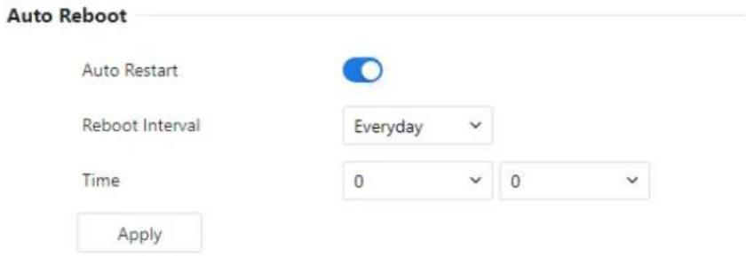
Auto Reboot Configuration:
You can also configure the device to reboot automatically at scheduled intervals.
D-Link F-Series Camera User Guide System Settings
Step 1 Enable Auto Reboot by checking the appropriate option.
Step 2 Choose the desired reboot interval from the drop-down list:
- Every Day
- Every Week
- Every Month
Figure 3-11 Camera auto restart
text_image
Auto Reboot Auto Restart Reboot Interval Everyday Time 0 0 ApplyStep 3 Click Apply. The auto reboot schedule will take effect, and settings will be saved.
3.8.2 Upgrade the Software Package
Description
You can upgrade the device software package through the web interface. This process ensures the device runs the latest version with improved features or resolved issues.
Procedure
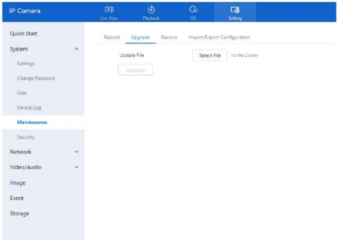
Step 1 Navigate to Setting > System > Maintenance > Upgrade. The Upgrade page is displayed.
D-Link F-Series Camera User Guide System Settings
Figure 3-12 Update file
text_image
IP Camera Live View Playback IVS Setting Quick Start System Settings Change Password User Device Log Maintenance Security Network Video/Audio Image Event Storage Reboot Upgrade Restore Import/Export Configuration Update File Select File No file Chosen UpgradeStep 2 Click Select File to browse and choose the appropriate upgrade file.
Step 3 Click Update to begin the upgrade process..
If the message "Updating, please wait a few minutes, and do not close the browser" is displayed:
• The upgrade is in progress.
• The device will automatically reboot after the update completes.
If another message is displayed, ensure you have selected the correct upgrade package and try again.

CAUTION
Do not power off the camera during the upgrade process. Power failure during an upgrade may result in device malfunction.
3.8.3 Restore Device to Factory Settings
Description
You can restore the device to its factory default settings. This feature is recommended in the following scenarios:
• The device configuration is incorrect, causing operational issues
- You want to reset all parameters
• A clean factory default state is required for troubleshooting

CAUTION
After clicking Restore, all configuration settings will be reset to factory defaults.
You may choose whether or not to retain the current IP address.
Use function carefully.
Procedure
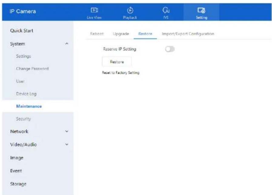
Step 1 Navigate to Setting > System > Maintenance > Restore. The Restore page is displayed.
Figure 3-13 Restore device
text_image
IP Camera Live View Playback MS Setting Quick Start System Settings Change Password User Device Log Maintenance Security Network Video/Audio Image Event Storage Reboot Upgrade Restore Import/Export Configuration Reserve IP Setting Restore Reset to Factory SettingStep 2 Click Restore. The message "Are you sure to restore?" is displayed. Step 3 Click OK. The device begins restoring to its factory default settings. After the process completes, the device will reboot with factory defaults applied.
3.8.4 Export / Import Configuration
Description
This feature allows you to back up the current configuration and restore it later. You can export the settings to a local hard drive and import the same configuration to:
D-Link F-Series Camera User Guide System Settings
• The current device
• Other cameras of the same model
The configuration file is saved as config.bin.
Procedure
Export Configuration
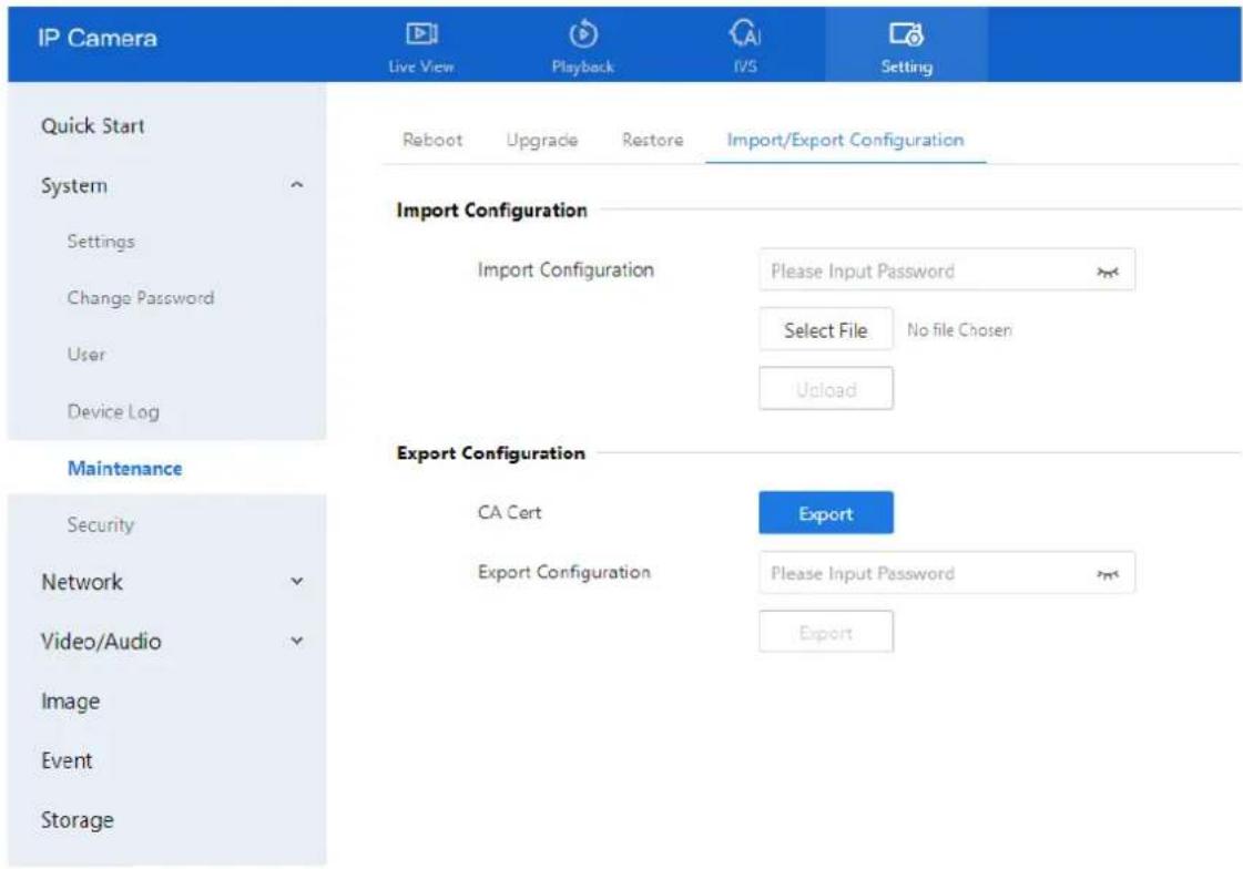
Step 1 Navigate to Setting > System > Maintenance > Import/Export Configuration. The Export / Import Configuration page is displayed (see Figure 3-14).
Step 2 Under Export Configuration:
- Enter the password.
○ Click Export.
Step 3 A message will appear: "Export Configuration File — Downloading, Please Wait!"
The configuration file will be downloaded to your local system.
Figure 3-14 Export / Import Configuration page
text_image
IP Camera Live View Playback IVS Setting Quick Start System Settings Change Password User Device Log Import Configuration Import Configuration Please Input Password Select File No file Chosen Upload Maintenance Security Network Video/Audio Image Event Storage Export Configuration CA Cert Export Export Configuration Please Input Password ExportExport Configuration File
Downloading, Please Wait!
Import Configuration
Step 1 Under Import Configuration:
- Enter the password.
D-Link F-Series Camera User Guide System Settings
- Click Select File, then browse and select the config.bin file from your local drive.
- Click Upload to begin the import process.
3.9 Configure Security
3.9.1 IP Filter
Description
The IP Filter function allows you to control access to the device based on IP address ranges. You can specify whether to allow or deny access to certain IP segments using whitelist or blacklist rules.
Procedure
Step 1 Go to Setting > System > Security > IP Filter.
The IP Filter page is displayed (see Figure 3-15).
Step 2 Click the toggle switch to enable IP Filter.
Step 3 Configure the parameters listed in Table 3-4.
Figure 3-15 IP filter page

text_image
IP Camera Live View Playback IVS Setting Quick Start System Settings Change Password User Device Log Maintenance Security Network Video/Audio Image Event Storage IP Filter HTTPS Certificate Security Services IP Filter Rule Type Black List Black List (Following Network Segments are Forbidden) + 盘 Begin IP Address End IP Address Description Edit ApplyTable 3-4 Parameters of IP filter
| Parameter | Description | Setting |
| IP Filter | Enables or disables the IP Filter function. | [Setting method]Click the button on.[Default value]OFF |
D-Link F-Series Camera User Guide
System Settings
| Parameter | Description | Setting |
| Rule Type | IP filter type, including black list and white list. | [Setting method]Select a value from the drop-down list box.[Default value]Black List |
| Black List | Specified network segment should be banned. | [Setting method]1. Click to enter the add black/white list page, as shown in Figure 3-162. Enter Begin IP Address.3. Enter End IP Address.4. Enter Description.5. Click OK, the black list added successfully. |
| White List | Allow specified network segment to access. | [Setting method]1. Click to enter the add black/white list page, as shown in Figure 3-16.2. Enter Begin IP Address.3. Enter End IP Address.4. Enter Description.5. Click OK, add the white list successfully. |
Figure 3-16 Add IP filter page
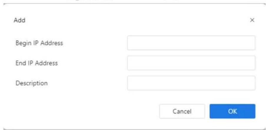
text_image
Add Begin IP Address End IP Address Description Cancel OK
NOTE
Click to modify the parameters of setting black list or white.
Click to delete the setting black list or white.
Step 4 Click Apply.
The If the message "Apply success!" appears, the IP Filter has been successfully configured.
3.9.2 HTTPS Certificate
Description
This section allows you to generate and install an HTTPS certificate for encrypted communication between the camera and your browser. You can create a certificate request, upload a third-party certificate, or manage existing certificates.
Procedure
Step 1 Navigate to Setting > System > Security > HTTPS Certificate.
The HTTPS Certificate page is displayed, as shown in Figure 3-17
Figure 3-17 HTTPS Certificate
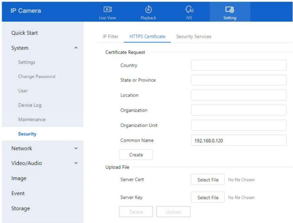
text_image
IP Camera Live View Playback IVS Setting Quick Start System Settings Change Password User Device Log Maintenance Security Network Video/Audio Image Event Storage IP Filter HTTPS Certificate Security Services Certificate Request Country State or Province Location Organization Organization Unit Common Name 192.168.0.120 Create Upload File Server Cert Select File No file Chosen Server Key Select File No file Chosen Delete UploadStep 2 Create the certificate request.
-
Fill in the certificate request details:
-
Country
• State or Province - Location
- Organization
- Organization Unit
-
Common Name (e.g., the device's IP address or domain name)
-
Click Create to generate the certificate request file.
- Send the generated file to a third-party Certificate Authority (CA) to obtain the signed certificate.
D-Link F-Series Camera User Guide
System Settings
- After receiving the certificate from the CA, click Select File under the appropriate field and upload it.
- Once successfully uploaded, the certificate will be visible and active on the HTTPS web interface.
To import the certificate from third party:
-
Under the Upload File section:
-
In the Server Cert field, click Select File and choose the certificate file issued by the CA.
• In the Server Key field, click Select File and upload the corresponding private key file. -
Click Upload to apply the certificate.
- Reboot the camera for the HTTPS certificate to take effect.
Delete an Existing Certificate
• To remove a previously uploaded certificate, click Delete.
Security Services
Description
To enhance device security, you can enable the Illegal Login Lock feature. When enabled, the system will lock the user account for a specified duration after a defined number of incorrect password attempts.
Procedure
Navigate to Setting > System > Security > Security Services.
The Security Services page is displayed, as shown in Figure 3-18.
D-Link F-Series Camera User Guide
System Settings
Figure 3-18 Security services page
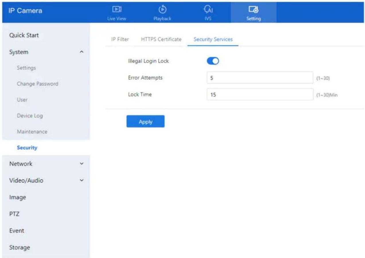
text_image
IP Camera Live View Playback IVS Setting Quick Start System Settings Change Password User Device Log Maintenance Security Network Video/Audio Image PTZ Event Storage IP Filter HTTPS Certificate Security Services Illegal Login Lock Error Attempts 5 (1~30) Lock Time 15 (1~30)Min ApplyStep 2 Configure the following settings:
- Illegal Login Lock: Toggle this switch ON to enable account lockout for failed login attempts.
- Error Attempts: Enter the number of allowed incorrect password attempts before lockout is triggered.
○ Range: 1–30
Example: Setting this to 5 means the account will be locked after 5 failed login attempts.
- Lock Time: Enter the duration (in minutes) for which the account will remain locked after exceeding the allowed attempts.
- Range: 1–30 minutes
Example: Setting this to 15 means the account will be locked for 15 minutes.
Step 3 Click Apply.
- A message "Apply success!" confirms that the settings have been saved.
4.4 Basic Settings
4.4.1 Local Network
For detailed information on Local Network Settings, please refer to Chapter 2.5
4.4.2 Device Port
Description
To enable proper network routing within a LAN, you must configure the following ports:
- HTTP Port
- Control Port
• RTSP (Real-Time Streaming Protocol) Port - HTTPS (SSL) Port
These ports are essential for web access, video streaming, and secure communication.
Procedure
Step 1 Navigate to Setting > Network > Settings > Device Port. The Device Port page is displayed (see Figure 4-1).
Step 2 Set the parameters, as shown in Table 4-1.
Figure 4-1 Device port page
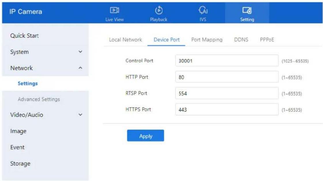
text_image
IP Camera Live View Playback IVS Setting Quick Start Local Network Device Port Port Mapping DDNS PPPoE System Control Port 30001 (1025-65535) Network HTTP Port 80 (1-65535) Settings Advanced Settings RTSP Port 554 (1-65535) Video/Audio HTTPS Port 443 (1-65535) Image Apply Event StorageD-Link F-Series Camera User Guide
Configure the Network Service
Table 4-1 Parameters of device port
| Parameter | Description | Setting |
| Control Port | Used for audio, video transmission, and signaling interaction. | [Setting method]Enter a value manually.[Default value]30001 |
| HTTP Port | ort used for standard web access.If changed (e.g., to 86), access the device using:http://192.168.0.120:86/ | [Setting method]Enter a value manually.[Default value]80 |
| RTSP Port | Port for RTSP protocol (streaming).Example: Inputrtsp://192.168.0.120:554/snl/live/1/1 into VLC to view live video.Refer toConfiguration>Protocol>ProtocolInfofor further details. | [Setting method]Enter a value manually.[Default value]554 |
| HTTPS Port | secure port for web access using SSL.Before use, ensureWeb Modeis set toHTTPS underConfiguration>Device>System.Access format:https://192.168.0.120:443 | [Setting method]Enter a value manually.[Default value]443 |
| SSL Control Port | Secure socket layer control port.Note:This option is available on select models only. | [Setting method]Enter a value manually.[Default value]20001 |

NOTE
It is generally not recommended to change the Control Port.
Refer to the Communication Matrix for valid port ranges for Control, HTTP, and SSL ports.
Step 3 Click Apply.
- If the message "Apply success!" appears, the settings have been saved.
D-Link F-Series Camera User Guide
Configure the Network Service
- If you see "Port invalid, please check it," review and re-enter valid port numbers.
4.4.3 Port Mapping
Description
Port mapping helps establish a mapping relationship between the private network and the external network. Port mapping allows outside computers to access intranet devices so that the network works efficiently.
Procedure
Step 1 Choose Setting > Network > Settings > Port Mapping.
The Port Mapping page is displayed, as shown in Figure 4-2.
Figure 4-2 Port mapping page

text_image
IP Camera Live View Playback NS Setting Quick Start Local Network Device Port Port Mapping DDNS PPPoE System Port Mapping Network Map Mode Auto Settings Auto Port Mapping Advanced Settings Video/Audio Status Port Type External Port External IP Address Status ✓ HTTP 80 0.0.0.0 Inactive ✓ RTSP 554 0.0.0.0 Inactive ✓ CONTROL 30001 0.0.0.0 Inactive ✓ HITPS 443 0.0.0.0 Inactive ApplyStep 2 Click the button on to enable Port Mapping.
Step 3 Set the parameters according to Table 4-2.
Table 4-2 Parameters of port mapping
| Parameter | Description | Setting |
| Port Mapping | Enables or disables the port mapping service. | [Setting method]Click the button on.[Default value]OFF |
| Map Mode | Defines how Auto and Manual ports are mapped | [[Setting method]Select a value from |
D-Link F-Series Camera User Guide
Configure the Network Service
| Parameter | Description | Setting |
| the drop-down list box.[Default value]Auto | ||
| Port Type | Types of ports used in the mapping:Includes SSL Control, HTTP, RTSP, Control, and HTTPS. | N/A |
| External Port | The port number used on the external (public) network. | [Setting method]Enter a value manually in map mode. |
| External IP Address | IP address used on the external network to access the device. | N/A |
| State | Displays the current mapping status for each port. | N/A |
Step 4 Click Apply.
- If the message "Apply success!" appears, the settings have been saved.
- If any other message appears, review and correct the parameters.
4.4.4 DDNS
Preparation
Before configuring DDNS, ensure that:
- The camera is connected to the Internet.
- You have obtained a valid username and password for logging into the Dynamic Domain Name System (DDNS) server.
Procedure
Step 1 Navigate to Setting > Network > Settings > DDNS. The DDNS page is displayed, as shown in Figure 4-3.
D-Link F-Series Camera User Guide
Configure the Network Service
Figure 4-3 DDNS page

text_image
IP Camera Live View Playback IVS Setting Quick Start Local Network Device Port Port Mapping DDNS PPPoE System DDNS Network Card Name eth0 Advanced Settings Host Name Video/Audio Account Event Password Test DDNS Storage ApplyStep 2 Click the toggle switch to enable DDNS.
Step 3 Configure the parameters as shown in Table 4-3.
Table 4-3 Parameters of DDNS
| Parameter | Description | Setting |
| DDNS | Enables or disables the DDNS service. | [Setting method]Click the button on to enable DDNS.[Default value]OFF |
| Provider | elect your DDNS service provider.Currently supported providers:3322_DDNDyndns | [Setting method]Select a value from the drop-down list box.[Default value]3322NOTESet this parameter based on the site requirements. |
| Network Card Name | Specifies which network card to use for DDNS. | [Setting method]Select a value from the drop-down list box.[Default value]Eth0 |
D-Link F-Series Camera User Guide
Configure the Network Service
| Parameter | Description | Setting |
| Host Name | Custom domain name set by the user. | [Setting method]Enter a value manually.[Default value]Blank |
| Accounts | Username for logging into the DDNS service. | [Setting method]Enter a value manually.[Default value]Blank |
| Password | Password for logging into the DDNS service. Note: Set all parameters according to your DDNS service provider's instructions and site requirements. | [Setting method]Enter a value manually.[Default value]Blank |
Step 4 Click Apply.
☐ If the message "Apply success!" appears, the configuration has been saved.
☐ If an error appears, review the settings and correct any incorrect values.
4.4.5
4.4.6 Set PPPoE
Preparation
Before configuring PPPoE, obtain your username and password from your Internet service provider (ISP).
Description
If the camera connects to the Internet via PPPoE (Point-to-Point Protocol over Ethernet), you must enter the provided credentials on the PPPoE configuration page. Once the device restarts, the PPPoE settings take effect, and the system will obtain a public IP address.
Procedure
Step 1 Navigate to Setting > Network > Settings > PPPoE.
The PPPoE page is displayed, as shown in Figure 4-4.
D-Link F-Series Camera User Guide
Configure the Network Service
Figure 4-4 PPPoE page

text_image
IP Camera Live View Playback IVS Setting Quick Start Local Network Device Port Port Mapping DDNS PPPoE System PPPoE Account Settings Password Advanced Settings Video/Audio IP Address Empty Image Apply Event StorageStep 2 Click the toggle button to enable PPPoE.
Step 3 Set the parameters according to Table 4-4.
Table 4-4 Parameters of PPPoE
| Parameter | Description | Setting |
| PPPoE | Click to enable PPPoE dialing. | [Setting method]Click the button on.[Default value]OFF |
| Accounts | User name of PPPoE provided by the network carrier. | [Setting method]Enter a value manually. |
| Password | Password of PPPoE provided by the network carrier. | [Setting method]Enter a value manually. |
Step 4 Click Apply.
- If the message "Apply success!" appears, the settings have been saved.
• If another message appears, review and correct the entered credentials.
Note: The IP address assigned via PPPoE will be displayed after a successful connection.
D-Link F-Series Camera User Guide
Configure the Network Service
4.5 Advanced Settings
4.5.1 Set FTP
Description
When FTP (File Transfer Protocol) Upload is enabled, the device will automatically send captured alarm snapshots (JPG images) to a designated FTP server.
Procedure
Step 1 Navigate to Setting > Network > Advanced Settings > FTP.
The FTP configuration page is displayed as shown in Figure 4-5.
Figure 4-5 FTP page

text_image
IP Camera Live View Playback IVS Setting Quick Start System Network Settings Advanced Settings Video/Audio Image Event Storage FTP SMTP HTTPS COS 802.1x SNMP ONVIF Platform Access Multicast Param CGI Alarm Service Center FTP Upload FTP Address FTP Port 21 Account Password FTP Path [Composed of numbers, letters, and underscores starting with / or ] Media Type Snapshot FTP Over SSU/TLS(FTPS) Test FTP ApplyStep 2 Click the toggle button to enable FTP Upload.
Step 3 Set the parameters as shown in Table 4-5.
Table 4-5 Parameters of FTP
| Parameter | Description | Setting |
| FTP Upload | Enables or disables FTP upload functionality. | [Setting method]Click the button on.[Default value]OFF |
| FTP Address | IP address of the FTP server. | [Setting method]Enter a value manually. |
| FTP Port | Port number of the FTP server. | [Setting method]N/A[Default value]21 |
D-Link F-Series Camera User Guide
Configure the Network Service
| Parameter | Description | Setting |
| Account | Username for FTP server login. | [Setting method]Enter a value manually. |
| Password | Password for FTP server login. | [Setting method]Enter a value manually. |
| FTP Path | FTP Path on the FTP server to store images. | [Setting method]Enter a value manually. |
| Media Type | Specifies the type of mediaSnapshot (JPG image)Video Clip (only if supported) | [Setting method]Select a value from the drop-down list box.[Default value]Snapshot |
| FTP over SSL/TLS (FTPS) | Enables encryption during file transfer using SSL/TLS. | [Setting method]Tick |
Step 4 Click Test FTP to verify the connection.
If "Test succeed" appears, the configuration is correct.
If "Test failed" appears, review and correct the FTP settings.
Step 5 Click Apply.
- If the message "Apply success!" appears, the configuration has been saved successfully.
- If an error message appears, revise the input accordingly.
4.5.2 Set SMTP
Description
If the Simple Mail Transfer Protocol (SMTP) function is enabled, the device will automatically send JPG images and alarm information to specified email addresses when an alarm is generated.
Procedure
Step 1 Choose Setting > Network > Advanced Settings > SMTP.
The SMTP page is displayed, as shown in Figure 4-6.
D-Link F-Series Camera User Guide
Configure the Network Service
Figure 4-6 SMTP page

text_image
IP Camera Live View Playback IVS Setting Quick Start System Network Settings Advanced Settings Video/Audio Image Event Storage FTP SMTP HTTPS QOS 802.1x SNMP ONVIF Platform Access Multicast Param CGI Alarm Service Center SMTP Server Address* SMTP Server Port* 25 User Email* Password* Send Anonymously Recipient_E-mail_Address1* Recipient_E-mail_Address2 Recipient_E-mail_Address3 Recipient_E-mail_Address4 Recipient_E-mail_Address5 Transport Mode No Encrypt Send interval 0 (0-60)s Image Number 1 (1-5) Image Interval 1 (0.1-5)S Email Test ApplyStep 2 Set the parameters according to Table 4-6.

NOTE
Fields marked with an asterisk (*) are mandatory.
Table 4-6 Parameters of SMTP
| Parameter | Description | Setting |
| SMTP Server Address | IP address of the SMTP server. | [Setting method]Enter a value manually. |
| SMTP Server Port | Port number of the SMTP server. | [Setting method]Enter a value manually.[Default value]25 |
| User Name | Username of the sender's email account. | [Setting method]Enter a value manually. |
| Password | Password for the sender's email account. | [Setting method]Enter a value manually. |
| Sender E-mail Address | Email address used to send alerts. | [Setting method]Enter a value manually. |
D-Link F-Series Camera User Guide
Configure the Network Service
| Parameter | Description | Setting |
| Recipient_E-mail_Addres s 1 | Primary recipient email address. | [Setting method]Enter a value manually. |
| Recipient_E-mail_Addres s 2 | Optional second recipient. | |
| Recipient_E-mail_Addres s3 | Optional third recipient. | |
| Recipient_E-mail_Addres s 4 | Optional fourth recipient. | |
| Recipient_E-mail_Addres s 5 | Optional fifth recipient. | |
| Attachment Image Quality | Higher quality uses more storage. Set based on requirements. | N/A |
| Transport Mode | Email encryption mode. Set this parameter based on the encryption modes supported by the SMTP server. | [Setting method]Select a value from the drop-down list box.[Default value]No Encrypted |
Step 3 Click Apply.
- If the message "Apply success!" appears, the settings have been saved successfully.
- If another message appears, review and correct any parameter errors.
4.5.3 Set HTTPS
Preparation
If users wish to access the camera's web interface securely via HTTPS, they must first configure the HTTPS port. For example, to access the web interface, input:
https://192.168.0.120:443
D-Link F-Series Camera User Guide
Configure the Network Service
Figure 4-7 HTTPS page

text_image
IP Camera Live View Playback IVS Setting Quick Start FTP SMTP HTTPS QOS 802.1x SNMP ONVIF Platform Access Multicast Param CGI Alarm Service Center System Status Network HTTPS Port 443 (1~65535) Settings Advanced Settings Video/Audio Apply4.5.4 Procedure
Step 1 Navigate to Setting > Network > Advanced Settings > HTTPS.
The HTTPS configuration page is displayed (see Figure 4-7).
Step 2 Toggle the Status switch to enable HTTPS.
Step 3 In the HTTPS Port field, enter the desired port number.
- Valid Range: 1–65535
Default: 443
Step 4 Click Apply.
- If the message "Apply success!" appears, the HTTPS configuration has been saved.
• You can now access the device securely using the designated port.
4.5.5 Set QOS
Description
If the device is connected to a router or switch that supports QoS (Quality of Service), and the network equipment is configured with appropriate priority rules, data packets from the device will be prioritized accordingly.
This setting helps ensure better performance and bandwidth management for critical services such as video streaming, alarms, and control commands.
Procedure
Step 1 Navigate to Setting > Network > Advanced Settings > QOS.
The QOS page is displayed, as shown in Figure 4-8.
D-Link F-Series Camera User Guide
Configure the Network Service
Figure 4-8 QOS page
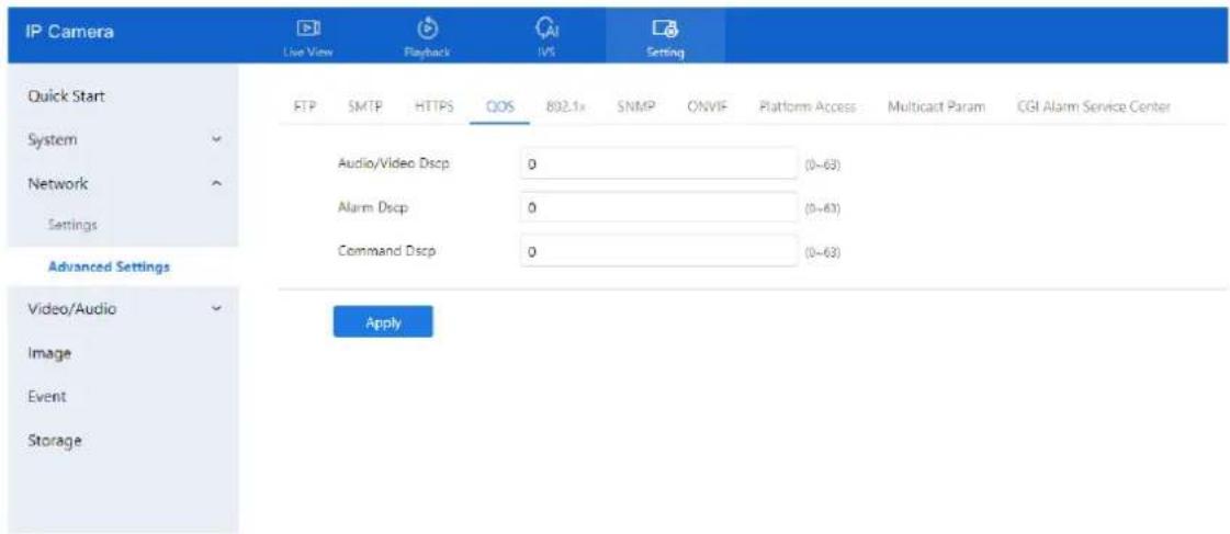
text_image
IP Camera Live View Playback IVS Setting Quick Start FTP SMTP HTTPS QOS 802.1x SNMP ONVIF Platform Access Multicast Param CGI Alarm Service Center System Audio/Video Dscp 0 (0-63) Network Alarm Dscp 0 (0-63) Settings Command Dscp 0 (0-63) Advanced Settings Video/Audio Apply Image Event StorageStep 2 Enter values for the following fields. Valid input range for each is 0–63:
• Audio/Video DSCP: Priority level for audio/video data
• Alarm DSCP: Priority level for alarm signals
• Command DSCP: Priority level for control commands
Step 3 Click Apply.
- If the message "Apply success!" appears, the settings have been successfully applied.
- If any error occurs, verify the DSCP values entered and correct them.
4.5.6 Set 802.1x
Preparation
Ensure that 802.1x authentication is configured on the device's network port. This standard verifies user identity and helps control access to network resources.
Procedure
Step 1 Navigate to Setting > Network > Advanced Settings > 802.1x.
The 802.1x configuration page is displayed, as shown in Figure 4-9.
D-Link F-Series Camera User Guide Configure the Network Service
Figure 4-9 802.1x page

text_image
IP Camera Live View Playback IVS Setting Quick Start FTP SMTP HTTPS QOS 802.1x SNMP ONVIF Platform Access Multicast Param CGI Alarm Service Center System ✓ 802.1x Network ✓ EAP Method EAP-MDS ✓ Settings Account Advanced Settings Password ✓ Video/Audio ✓ Confirm Password ✓ Image Event Apply StorageStep 2 Toggle the 802.1x switch to enable authentication.
Step 3 Choose the EAP Method (Extensible Authentication Protocol) from the drop-down list:
- EAP-MD5
• EAP-TLS
Step 4 Enter the Account Name.
Step 5 Enter and confirm the Password.
Step 6 Click Apply.
If the message "Apply success!" is displayed, the settings have been saved successfully.
4.5.7 Set SNMP
Description
Simple Network Management Protocol (SNMP) is an internet-standard protocol used for managing devices on IP networks. This system supports:
• SNMPv1
- SNMPv2c
• SNMPv3
Each version has unique security models and configuration parameters.
Procedure
Step 1 Navigate to Setting > Network > Advanced Settings > SNMP. The SNMP page is displayed, as shown in Figure 4-10.
D-Link F-Series Camera User Guide
Configure the Network Service
Figure 4-10 SNMP page

text_image
IP Camera Live View Playback IVS Setting Quick Start System Network Settings Advanced Settings Video/Audio Image Event Storage FTP SMTP HTTPS QOS 802.1x SNMP ONVIF Platform Access Multicast Param CGI Alarm Service Center SNMPv1 SNMPv2c Write Community Read Community Trap Address Trap Port 162 Trap Community SNMPv3 SNMP Port 161 ApplyStep 2 Toggle the appropriate buttons to enable SNMPv1, SNMPv2c, or SNMPv3.
Step 3 Configure parameters as shown in Table 4-7.
D-Link F-Series Camera User Guide
Configure the Network Service
Table 4-7 Parameters of SNMP
| Parameter | Description | Setting |
| SNMPv1 | Version of SNMP. SNMPv1 and SNMPv2c use communities to establish trust between managers and agents. Agents support three community names, write community, read community and trap. | [Setting method]Click the button on.[Default value]OFF |
| SNMPv2c | ||
| Write Community | Name of write community.The write community only can modify data. | [Setting method]Enter a value manually. |
| Read Community | Name of read community.The write community only can read data. | |
| Trap Address | IP address of the trap. | |
| Trap Port | Management port of accepting message from trap. | |
| Trap Community | Community string of trap.The trap community string allows the manager to receive asynchronous information from the agent. | |
| SNMPv3 | Version of SNMP.SNMPv3 uses community strings, but allows for secure authentication and communication between SNMP manager and agent. | [Setting method]Click the button on.[Default value]OFF |
| Read Security Name | Name of read security. | [Setting method]Enter a value manually. |
| Write Security Name | Name of write security. | |
| Security Level | Security Level between SNMP manager and agent, includes three levels:No auth: No authentication and no encryptionAuth: Authentication but no encryptionPriv: Authentication and encryption | [Setting method]Select a value from the drop-down list box.[Default value]Blank |
D-Link F-Series Camera User Guide
Configure the Network Service
| Parameter | Description | Setting |
| Auth Algorithm | Authentication Algorithm, includes MD5and SHA. | [Setting method]Select a value from the drop-down list box.[Default value]Blank |
| Auth Password | Authentication password. | [Setting method]Enter a value manually. |
| Encrypt Algorithm | Encryption Algorithm, includes DES and AES. | [Setting method]Select a value from the drop-down list box.[Default value]Blank |
| Encrypt Password | Encryption password. | [Setting method]Enter a value manually. |
| SNMP Port | Port of SNMP. | [Setting method]Enter a value manually.[Default value]161 |
Step 4 Click Apply.
- If the message "Apply success!" is displayed, your SNMP settings are saved.
- If another message appears, verify and correct the configuration.
4.5.8 View ONVIF
Description
The ONVIF page displays details about the protocol configuration used for external integration with ONVIF-compliant systems.
Procedure:
Step 1 Navigate to Setting > Network > Advanced Settings > ONVIF.
The ONVIF page is displayed, as shown in Figure 4-11. Table 4-8 describes the protocol-related parameters
D-Link F-Series Camera User Guide
Configure the Network Service
Figure 4-11 ONVIF page
| IP Camera Live View Playback IVS Setting | |||||||||||
| Quick Start System Network Settings Advanced Settings Video/Audio Image Event Storage | FTP | SMTP | HTTPS | QOS | B02.1x | SNMF | ONVIF | Platform Access | Multicast Param | CGI Alarm Service Center | |
| Protocol Name | ONVIF | ||||||||||
| Protocol Version | v22.06 | ||||||||||
| Protocol Software Version | v22.06_build000528 | ||||||||||
| RTSP Format | rtsp://ip:port/snl/live/cameraid/streamid | ||||||||||
| RTSP Example | rtsp://192.168.0.120:554/snl/live/1/1 | ||||||||||
| Onvif UUID | 09kb5d40-e227-11ee-9a2f-001c27154578 | ||||||||||
| User Verification | |||||||||||
| Onvif | |||||||||||
| Profile G | |||||||||||
| Media2 | |||||||||||
| Metadata Stream | |||||||||||
| Image Event | |||||||||||
| Intelligent Analysis Switch | |||||||||||
| Onvif Only Https Stream Only Https Apply Onvif Only Https Apply Onvif Only Https Apply Onvif Only Https Apply Onvif Only Https Apply Onvif Only Https Apply Onvif Only Https Apply Onvif Only Https Apply Onvif Only Https Apply Onvif Only Https Apply Onvif Only Https Apply Onvif Only Https Apply Onvif Only Https Apply Onvif Only Https Apply Onvif Only Https Apply Onvif Only http http http http http http http http http http http http http http http http http http http http http http http http http http http http http http http http http http http http http http http http http http http http http http http http http http http http http http http http http http http http http http http http http http http http http http http http http http http http http http http http http http http http http http http http http http http http http http http http http http http httphttp http http http http http http http http http http http http http http http http http http http http http http http http http http http http http http http http http http http http http http http http http http http http http http http http http http http http http http http http http http http http http http http http http http http http http http http http httphttphttphttphttphttphttphttphttphttphttphttphttphttphttphttphttphttphttphttphttphttphttphttphttphttphttphttphttphttphttphttphttphttphttphttphttphttphttphttphttphttphttphttphttphttphttphttphttphttphttphttphttphttphttphttphttphttphttphttphttphttphttphttphttphttphttphttphttphttphttphttphttphttphttphttphttphttphttphttphttphttphttphttphttphttphttphttphttphttphttphttphttphttphttphttphttphttphttphttphttpwww.hua.com.cn Application Open Access Platform Access Platform Access Platform Access Platform Access Platform Access Platform Access Platform Access Platform Access Platform Access Platform Access Platform Access Platform Access Platform Access Platform Access Platform Access Platform Access Platform Access Platform Access Platform Access Platform Access Platform Access Platform Access Platform Access Platform Access Platform Access Platform Access Platform Access Platform Access Platform Access Platform Access Platform Access Platform Access Platform Access Platform Access Platform Access Platform Access Platform Access Platform Access Platform Access Platform Access Platform Access Platform Access Platform Access Platform Access Platform Access Platform Access Platform Access Platform Access Platform Access Platform Access Platforms, Platforms, Platforms, Platforms, Platforms, Platforms, Platforms, Platforms, Platforms, Platforms, Platforms, Platforms, Platforms, Platforms, Platforms, Platforms, Platforms, Platforms, Platforms, Platforms, Platforms, Platforms, Platforms, Platforms, Platforms, Platforms, Platforms, Platforms, Platforms, Platforms, Platforms, Platforms, Platforms, Platforms, Platforms, Platforms, Platforms, Platforms, Platforms, Platforms, Platforms, Platforms, Platforms, Platforms, Platforms, Platforms, Platforms, Platforms, Platforms, Platforms, Platforms 10000000000000000000000000000000000000000000000000000000000000000000000000000000000000000000000000000 1 2 3 4 5 6 7 8 9 10 11 12 13 14 15 16 17 18 19 20 21 22 23 24 25 26 27 28 29 30 31 32 33 34 35 36 37 38 39 40 41 42 43 44 45 46 47 48 49 50 51 52 53 54 55 56 57 58 59 60 61 62 63 64 65 66 67 68 69 70 71 72 73 74 75 76 77 78 79 80 81 82 83 84 85 86 87 88 89 90 91 92 93 94 95 96 97 98 99 100 | |||||||||||
Table 4-8 Parameters of protocol-related
| Parameter | Description |
| Protocol Name | Type of the access protocol. |
| Protocol Version | Version number of the access protocol. |
| Protocol Software Version | Software version number of the access protocol. |
| RTSP Format | URL rule of Real Time Streaming Protocol. |
| RTSP Example | URL example of Real Time Streaming Protocol. |
| Onvif UUID | Universally Unique Identifier. |
D-Link F-Series Camera User Guide Configure the Network Service
| Parameter | Description |
| User Verification | When you select the User Verification check box, the user name and password must be the same as those for logging in to the device web page.NOTEWhen an ONVIF-compliant device connects to the platform, you must authenticate the user name and password to ensure the connection security. |
| Onvif | Enable Onvif |
| Profile G | Enable Onvif profile G |
| Intelligent Analysis Switch | Enable intelligent analysis switch |
| Media 2 | Enable media 2 |
| Image Event | Enable image event |
| Intelligent Analysis Switch | Enable active onvif |
| Onvif only Https | Onvif can use a more secure HTTPS mode for connection, command interaction and video data transmission, which are transmitted in an encrypted way to enhance network security. |
| Stream only https |
Step 2 Click Apply.
A confirmation dialog appears. Click Confirm to restart the device and apply changes.
4.5.9 Set Platform Access
Description
Use Platform Access to connect the IP camera to a centralized management platform outside the local network. This is useful when the device and the platform are on different networks.
You must prepare and configure a platform server in advance.
Ensure that port forwarding or NAT mapping is set on the external network.
Procedure
Step 1 Navigate to Setting > Network > Advanced Settings > Platform Access. The Platform Access page is displayed, as shown in Figure 4-12
D-Link F-Series Camera User Guide
Configure the Network Service
Figure 4-12 Platform access page

text_image
IP Camera Live View Playback NVS Setting Quick Start FTP SMTP HTTPS QOS 802.1x SNMP ONVIF Platform Access Multicast Param CGI Alarm Service Center System Network Settings Advanced Settings Video/Audio Image Event Storage Platform Access Host Name Port 0 (1~65535) User Name Password Encrypt ApplyStep 2 Input the following connection parameters:
- Host Name: Enter the IP address or domain name of the external platform server.
• Port: Port used by the platform. - User Name and Password: Credentials that match the platform login.
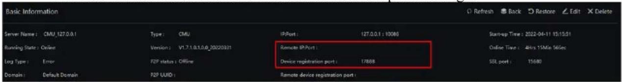
text_image
Basic Information Server Name: CMU,127.0.0.1 Type: CMU iP-Port 127.0.0.1 : 10065 Start-up Time: 2022-04-11 15:15:51 Running State: Online Version: V1.7.1.0.1.0.0_20220331 Remote IP-Port: Log Type: Error F2P status: Offline Device registration port: 17888 SSL port: 15680 Domain: Default Domain F2P UUID Remote device registration port:Step 3 When adding the IP camera to the platform, use the following information:
• IP / ID / Domain Name: Device ID of the IP camera.
- Connection Mode: Choose Device Active Registration.

text_image
+ AddDevice Device Name Device Type IPC Protocol Private Protocol IP/ID/ domain name Port 30001 Group Default group Advanced setting Connection mode Device active registration IAU Not Support MDU Auto Save and New Test Add Cancel
Device Info
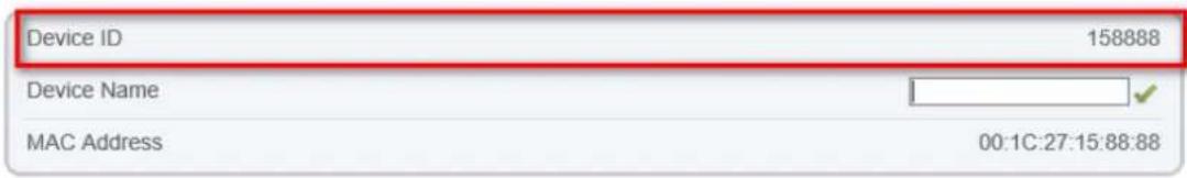
text_image
Device ID 158888 Device Name MAC Address 00:1C:27:15:88:88Step 4 Enable Encrypt to secure the connection between the camera and the platform. Step 5 Click Apply.
If the message "Apply success!" appears, the settings are saved and applied.
4.5.10 Set Multicast Parameters
Description
This section allows you to configure multicast streaming settings, including stream ID, video/audio ports, and source addresses for efficient data distribution across multicast-capable networks.
Procedure
Step 1 Navigate to Setting > Network > Advanced Settings > Multicast Param.
The Multicast Param page is displayed as shown in Figure 4-13. Table 4-9 describes the parameters on the Multicast Param page.
Figure 4-13 Multicast param page
| IP Camera Live View Playback INS Setting Quick Start System Network Settings Advanced Settings Video/Audio Image Event Storage | FTP | SMTP | HTTPS | QOS | 602.1x | SNMP | ONVIF | Platform Access Multicast Param CGI Alarm Service Center | |||
| Stream ID | 1 | ||||||||||
| Video Port | 25330 | (1025~65535) | |||||||||
| Video Address | 238,255,255,255 | ||||||||||
| Audio Port | 25430 | (1025~65535) | |||||||||
| Audio Address | 238,255,255,255 | ||||||||||
| Source Port | 25530 | (1025~65535) | |||||||||
| Source Address | 238,255,255,255 | ||||||||||
| Apply | |||||||||||
Table 4-9 Parameter description
| Parameter | Description | Setting |
| Stream ID | ID for the stream. | [Setting method]Select a value from the drop-list box.[Default value]1 |
| Video address | IP address to receive video multicast data. | [Setting method]Enter a value manually.[Default value]238.255.255.255 |
| Video Port | Port for receiving video stream. | [Setting method]Enter a value manually.[Default value]25330 |
D-Link F-Series Camera User Guide Configure the Network Service
| Parameter | Description | Setting |
| Audio Port | Port for receiving audio stream. | [Setting method]Enter a value manually.[Default value]25430 |
| Source Port | Port for receiving source data. | [Setting method]Enter a value manually.[Default value]25530 |
Step 2 Click Apply.
A confirmation message will appear. Settings take effect after the device restarts.
4.5.11 Set CGI Alarm Service Center
Description
When enabled, the device can send alarm messages using CGI (Common Gateway Interface) through specified Start URL and End URL using the HTTP protocol. Alarm data is embedded in the User-Agent field of HTTP headers and forwarded to a configured CGI server.
Procedure
Step 1 Navigate to Setting > Network > Advanced Settings > CGI Alarm Service Center. The page is displayed, as shown in Figure 4-14.
D-Link F-Series Camera User Guide Configure the Network Service
Figure 4-14 CGI alarm service center page
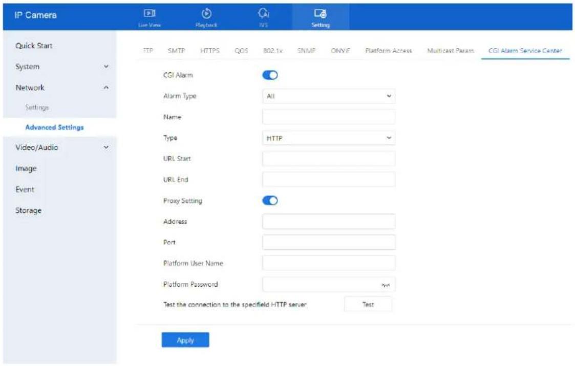
text_image
IP Camera User View Playback IVS Setting Quick Start System Network Settings Advanced Settings Video/Audio Image Event Storage FTP SMTP HTTPS QOS 802.1x SNMF ONVIF Platform Access Multicast Params CGI Alarm Service Center CGI Alarm Alarm Type All Name Type HTTP URL Start URL End Proxy Setting Address Port Platform User Name Platform Password Test the connection to the specifield HTTP server. Test ApplyStep 2 Click the toggle to enable CGI Alarm. Step 3 Set the parameters according to Table 4-10.
Table 4-10 Parameters of CGI Alarm service center
| Parameter | Description | Setting |
| CGI Alarm | Enable or disable CGI alarm functionality. | [Setting method]Click the button on.[Default value]OFF |
| Alarm Type | Enable or disable CGI alarm functionality. | [Setting method]Select a value from the drop-down list box.[Default value]All |
| Name | Custom name for the CGI alarm. | [Setting method]Enter a value manually. |
| Type | Protocol type for pushing the alarm (e.g., HTTP). | [Setting method]Select a value from the drop-down list box.[Default value]HTTP |
| URL Start | URL to which the alarm is pushed at end. | [Setting method]Enter a value manually.For example:http://192.168.35.74:80/MajorAlarmType&MinorAlarmType&SourceName&DeviceID&DeviceIP&AlarmTime&Description |
| URL End | URL to which the alarm is pushed at end. | [Setting method]Enter a value manually.For example:http://192.168.35.74:80/MajorAlarmType&MinorAlarmType&SourceName&DeviceID&DeviceIP&AlarmTime&Description |
| Proxy Setting | Enable proxy for forwarding CGI alarms. | [Setting method]Click the button on.[Default value]OFF |
| Address | IP address of the proxy server | [Setting method]Enter a value manually. |
| Port | Proxy server port. | [Setting method]Enter a value manually. |
| Platform User Name | Username for proxy platform login. | [Setting method]Enter a value manually. |
| Platform Password | Password for proxy platform login. | [Setting method]Enter a value manually. |
| Test the connection to the specified HTTP server | Test if the device connects to the proxy successfully. | [Setting method]Click Test, if the device connects to the proxy successfully, the message “Test CGI alarm success” is displayed. |
Step 4 Click Apply.
- If "Apply success!" appears, the settings are saved.
- If "Parameter is invalid" appears, check and correct the configuration.
5 Configuration Video/Audio
5.4 Video
5.4.1 Set video
For detailed instructions on setting video parameters, please refer to Chapter 2.5
5.4.2 Snapshot
Procedure
Step 1 Navigate to Setting > Video/Audio > Snapshot.
The Snapshot configuration page is displayed, as shown in Figure 5-1.
Figure 5-1 Snapshot configuration page
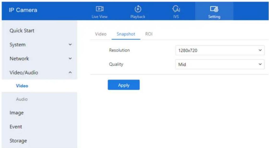
text_image
IP Camera Live View Playback IVS Setting Quick Start Video Snapshot ROI System Resolution 1280x720 Network Quality Mid Video/Audio Apply Audio Image Event StorageStep 2 Set the parameters according to Table 5-1.
Table 5-1 Parameters of snapshot configuration
| Parameter | Description | Setting |
| Snapshot Resolution | Choose resolution of snapshot. | [Setting method]Select a value from the drop-down list box.[Default value]1280*720 |
| Snapshot Quality | Choose the quality of snapshot. | [Setting method]Click the button.[Default value]Mid |
5.4.3 ROI Parameter
Procedure
Step 1 Navigate to Setting > Video/Audio > Snapshot. The Snapshot configuration page is displayed as shown in Figure 5-2.
Figure 5-2 ROI configuration page
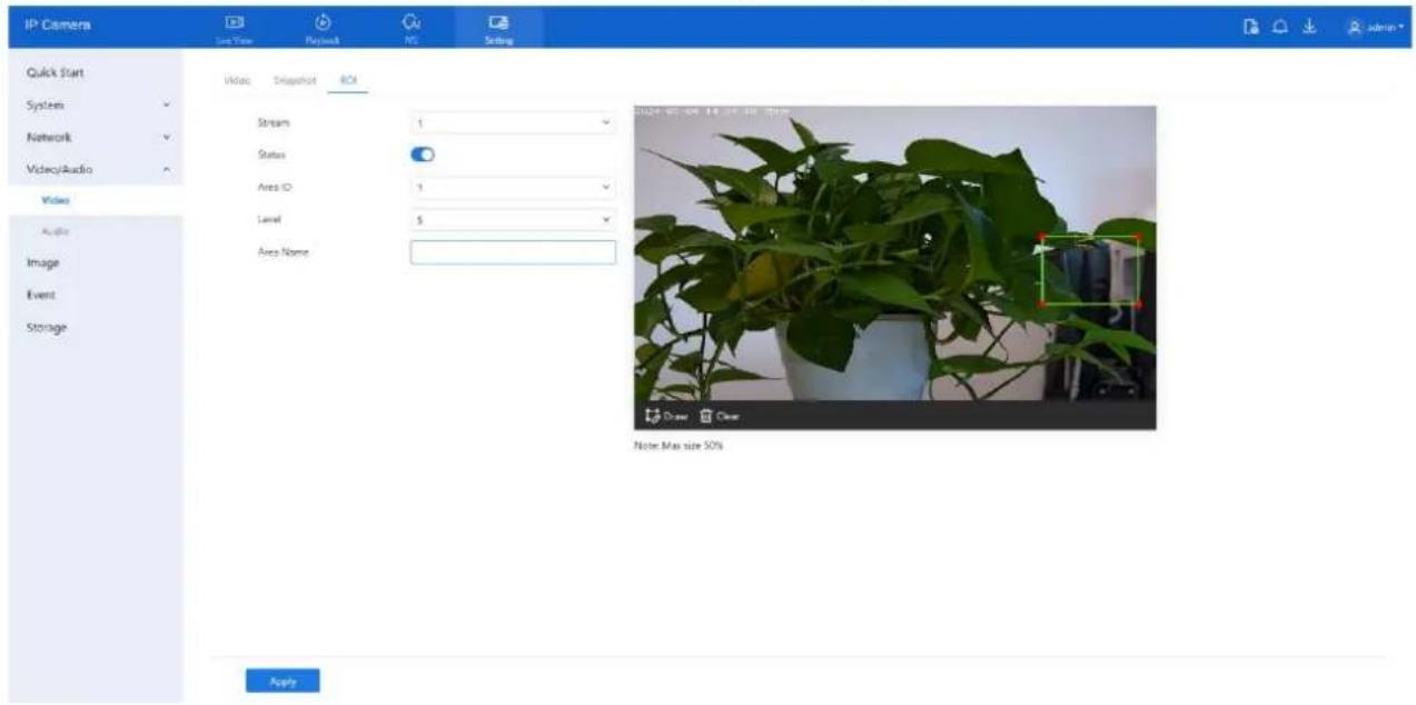
text_image
IP Camera Last View Playback NG Setting Quick Start System Network Video/Audio Video Audio Image Event Storage Video Snapshot ROI Stream 1 Status Area ID 1 Level 5 Area Name 2024-06-20 14.00 am size: 50% Draw Clear Note Max size 50% ApplyStep 2 Set the parameters according to Table 5-2.
Table 5-2 Parameters of ROI
| Parameter | Description | Setting |
| Channel | For general cameras, the default is channel 1. For bi-spectrum cameras, 1 is optical channel, 2 is thermal channel. | [Setting method]Select a value from the drop-down list box.[Default value]Stream 1 |
D-Link F-Series Camera User Guide
Configuration Video/Audio
| Parameter | Description | Setting |
| Stream | Stream ID. | [Setting method]Select a value from the drop-down list box.[Default value]Stream 1 |
| Status | Enable or disable the ROI | [Setting method]Click the button.[Default value]OFF |
| Area ID | ROI area ID | [Setting method]Select a value from the drop-down list box.[Default value]1 |
| Level | The visual effect of ROI. The higher the level is, the clearer the area is; the more blurred outside the area. | [Setting method]Select a value from the drop-down list box.[Default value]5 |
| Area Name | The marked name used for areas. | [Setting method]Enter a value manually. The value cannot exceed 32 bytes. |
Step 3 Click Draw to show the red frame, drag the four corners of rectangle to adjust the position.
Step 4 Click Apply.
If the message "Apply success!" is displayed, the settings have been saved.
5.5 Audio
5.5.1 Audio
Description
On this page, you can configure audio input and output settings, including type, volume, and noise reduction.
Procedure
Step 1 Navigate to Setting > Video/Audio > Audio. The Audio Input page is displayed, as shown in Figure 5-3. Table 5-3 describes the parameters.
Figure 5-3 Audio input page
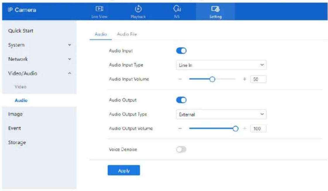
text_image
IP Camera Live View Playback INS Setting Quick Start System Audio Audio File Audio Input Audio Input Type Line In Audio Input Volume - + 50 Audio Audio Output Audio Output Type External Audio Output Volume - + 100 Audio Image Event Storage Voice Denoise ApplyTable 5-3 Parameters of audio input
| Parameter | Description | Setting |
| Enable Audio Input | Indicates whether to enable the audio input function. | [Setting method]Click the button on to enable audio input. |
| Audio Input Type | Audio input types include:Line In / InternalAn active audio input is required. | [Setting method]Select a value from the drop-down list box. |
| Audio Input Volume | Allows you to adjust the audio input volume. | [Setting method]Slide the slider left or right.[Default value]50NOTEThe value ranges from 0 to 100. |
| Enable Audio Output | Indicates whether to enable the audio output function. | [Setting method]Click the button on to enable audio output. |
D-Link F-Series Camera User Guide
Configuration Video/Audio
| Parameter | Description | Setting |
| Audio Output Type | Microphone types include:☐ ExternalAn active audio output is required.Internal means the camera own speaker. | [Setting method]Select a value from the drop-down list box. |
| Audio output Volume | Allows you to adjust the audio output volume. | [Setting method]Slide the slider left or right.[Default value]50NOTEThe value ranges from 0 to 100. |
| Voice Denoise | Reduces background noise on internal mic. | [Setting method]Click the button on to enable. |
Step 2 Click Apply.
If "Apply success!" is displayed, the settings have been saved.
5.5.2 Audible File (Feature available only on certain models) Procedure:
Step 1 Navigate to Setting > Video/Audio > Audio > Audio File.
The Audio File configuration page is displayed, as shown in Figure 5-4.
- Volume for playback can be adjusted at Setting > Video/Audio > Audio > Audio Output, as shown in Figure 5-4.
D-Link F-Series Camera User Guide Configuration Video/Audio
Figure 5-4 Audio file page
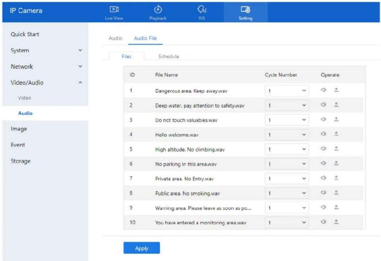
text_image
IP Camera Live View Playback IVS Setting Quick Start System ✓ Audio Audio File Files Schedule Network ✓ Video/Audio ✓ Audio ID File Name Cycle Number Operate 1 Dangerous area. Keep away.wav 1 ✓ ◄ ↑ 2 Deep water. pay attention to safety.wav 1 ✓ ◄ ↑ 3 Do not touch valuables.wav 1 ✓ ◄ ↑ 4 Hello welcome.wav 1 ✓ ◄ ↑ 5 High altitude. No climbing.wav 1 ✓ ◄ ↑ 6 No parking in this area.wav 1 ✓ ◄ ↑ 7 Private area. No Entry.wav 1 ✓ ◄ ↑ 8 Public area. No smoking.wav 1 ✓ ◄ ↑ 9 Warning area. Please leave as soon as pc... 1 ✓ ◄ ↑ 10 You have entered a monitoring area.wav 1 ✓ ◄ ↑ ApplyStep 2 The interface provides a list of 13 default audio files. For each file, you can:
- Set Cycle Number: The number of times the file will play when triggered.
- Test Playback: Click the 📋 (speaker icon) to listen to the file.
Step 3 To upload a custom audio file:
- Click the Upload icon.
- In the upload window, select a WAV file from your computer.
- File requirements:
- Format: .wav
• Size: less than 250 KB - Bitrate: 128 kbps
- Click Apply to upload the file.
Step 4. Click Apply to save the overall audio alarm configuration.
Step 5 CCVC Proceed to configure the armed schedule to define when audible alarms should be triggered.
6 Configuration Image
6.4 Configure Display
For detailed information, please refer to Chapter 2.3.
6.5 Configure OSD
For detailed information, please refer to Chapter 2.4
6.6 Configure the Privacy Mask
Procedure
Step 1 Navigate to Setting > Image > Privacy Masking. The Privacy Masking page is displayed, as shown in Figure 6-1.
Figure 6-1 Privacy masking page

text_image
IP Camera Live View Display I/O Setting Quick Start Display OSD Privacy Masking Video Standard System Network Video/Audio Image Event Storage PTZ 2024-01-04 05:11:28 They 3D Draw Clear Privacy Masking List Add ID Name Type Color Status Operate SaveStep 2 Click Draw to display a red frame over the video preview. Drag the four corners of the rectangle to adjust its position and size.
Step 3 Click Clear to remove the selected frame.

NOTE
- The maximum maskable area depends on the device model (refer to on-screen tips).
• You can mask up to four areas.
- To delete a masking area: Tick the corresponding ID in the Privacy Masking List, then click Delete.
Step 4 Set the parameters according to Table 6-1.
Table 6-1 Parameters of privacy masking
| Parameter | Description | Setting |
| ID | Identifier for each masking area. | N/A |
| Name | Name for the masking area. | [Setting method]Click the name and enter a value manually.[Default value]Blank |
| Type | Type of privacy masking. | [Setting method]Select a value from the drop-down list box.[Default value]Color Block |
| Color | Color of privacy masking. | [Setting method]Select a value from the drop-down list box.[Default value]Black |
| Enable | Indicates whether to enable the privacy masking. | [Setting method]Select a value from the drop-down list box.[Default value]Yes |
| Delete | Delete a privacy masking. | [Setting method]6. Select a privacy masking from the Privacy Masking List.7. Click Delete, the privacy masking is deleted successfully |
| Modify | Modify a privacy masking. | [Setting method]8. Select a privacy masking from the Privacy Masking List.9. Click a parameter and modify it.10. Click Modify, the privacy masking is modified successfully |
Step 5 Click Add to add privacy masking.
6.7 Configure Video Standard
Procedure
Step 1 Navigate to Setting > Image > Video Standard.
The Camera page is displayed, as shown in Figure 6-2. Set the video format parameters according to Table 6-2.
Figure 6-2 Camera page
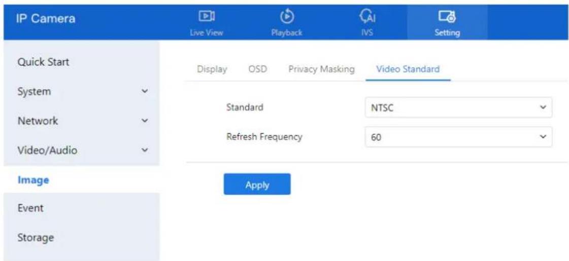
text_image
IP Camera Live View Playback IVS Setting Quick Start Display OSD Privacy Masking Video Standard System ✓ Standard NTSC ✓ Network ✓ Refresh Frequency 60 ✓ Video/Audio ✓ Image Apply Event StorageTable 6-2 Parameters of camera
| Parameter | Description | Setting |
| Video System | The options are as follows:☐ PAL: Used in Europe and China mainland, India, Pakistan, etc.☐ NTSC: Used in USA, Japan, South Korea, and Taiwan Province of China, etc. | [Setting method]Select a value from the drop-down list box.[Default value]PALNOTEWhether the video system can be changed depends on the device model. |
| Video Refresh Frequency | The options are as follows:☐ 50 Hz: corresponds to the PAL system.☐ 60 Hz: corresponds to NTSC system. | [Setting method]Follow the video standard. |
Step 2 Click Apply. If the message "Apply success!" is displayed, the settings are saved..

NOTE
If the message "The device will restart, are you sure to modify?" appears, confirm to proceed.
The system will restart and apply the new video standard.
7 Configure Event
Alarm linkage actions vary by camera model and hardware capabilities. Please refer to your specific device documentation for supported features.
7.4 Motion Alarm Linkage
Description
The Motion Alarm page allows you to:
- Enable or disable motion detection.
- Configure detection schedules and areas.
- Link motion events to alarms (e.g., audible alerts, recordings, light signals).
- Trigger notifications via FTP or SMTP.
When motion is detected within a predefined area and schedule, the camera generates an alarm and triggers the configured linkage actions.
Procedure
Step 1 Go to Setting > Event > Motion Alarm.
The Motion Alarm page is displayed, as shown in Figure 7-1.
Figure 7-1 Motion alarm page
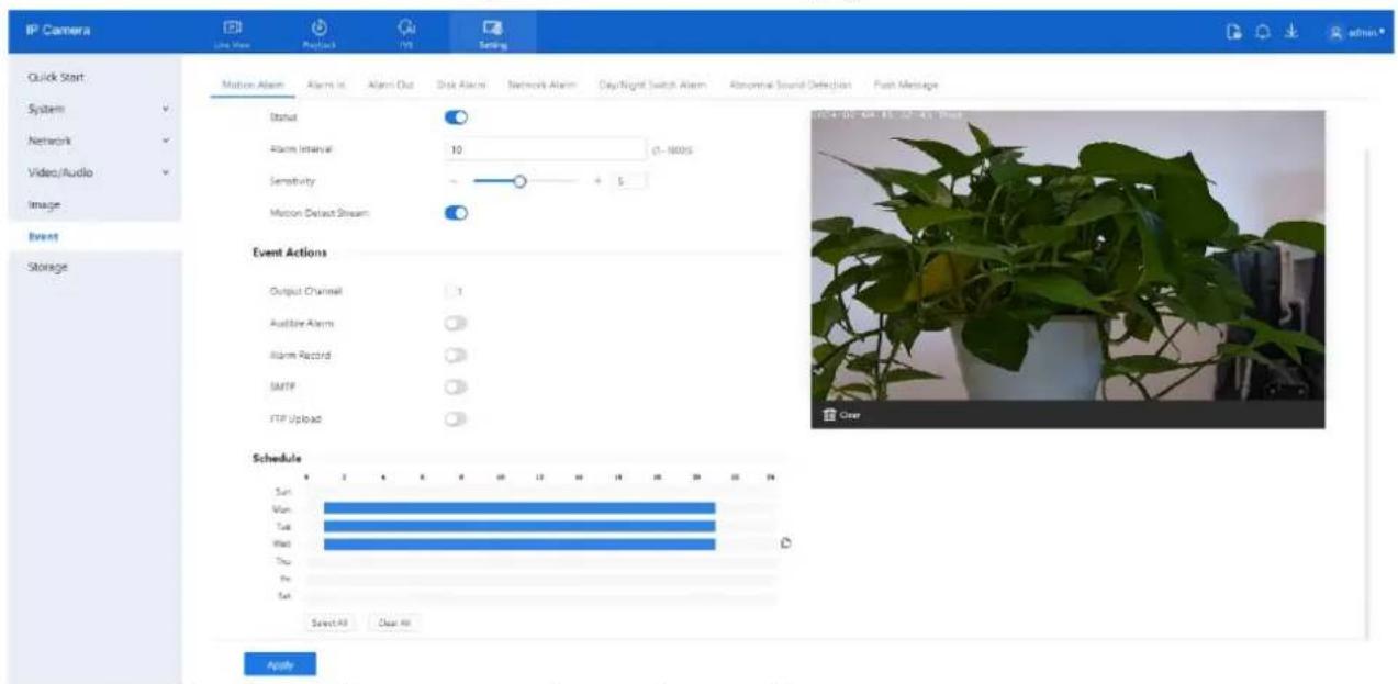
text_image
IP Camera Live View Positive 10 Settings Quick Start System Network Video/Audio Image Event Storage Motion Alarm Alarm In Alarm Out Disk Alarm Network Alarm Day/Night Switch Alarm Abnormal Sound Detection Push Message Status Alarm Interval 10 0-1600S Sensitivity + 5 Motion Default Stream Event Actions Output Channel 1 Audience Alarm Alarm Record SMTP FTP Upload Schedule Sun Vee Tue Wed Thu Fri Sat Select All Clear All ApplyStep 2 Configure all parameters, please refer to Table 7-1.
D-Link F-Series Camera User Guide
Configure Event
Table 7-1 Motion alarm parameters
| Parameter | Description | Setting |
| Status | Enables or disables motion detection. | [How to set]Click Enable to enable.[Default value]OFF |
| Alarm Interval | Sets the time interval (1–1800 seconds) during which repeated alarms are suppressed. | [How to set]Input a value, 1~1800s |
| Sensitivity | Determines motion detection sensitivity. Higher values detect smaller movements but may reduce accuracy. | [How to set]Choose from the drop-down list[Default value]5 |
| Motion Detect Stream | Enables or disables motion detection. | [How to set]Click to enable[Default value]OFF |
| Output Channel | Enables or disables motion detection. | [How to set]Click to select an ID. |
| Audible Alarm | Triggers audio warning playback (configured in Setting > Video/Audio > Audio File). | [How to set]Click to enable Audible alarm[Default value]OFF |
| Alarm Record | Records alarm-triggered video to the SD card. | [How to set]Click to enable alarm record.[Default value]OFF |
| SMTP | Sends alarm notifications via email. SMTP must be configured.. | [How to set]Click to enable SMTP.[Default value]OFF |
| FTP Upload | Uploads alarm snapshots to an FTP server. FTP must be configured. | [How to set]Click to enable FTP Upload.[Default value]OFF |
D-Link F-Series Camera User Guide
Configure Event
| Parameter | Description | Setting |
| White Light Alarm | The camera should have white light or dual lights.Flickers white light during an alarm (only on supported models). | [Setting method]Click to enable White Light Alarm[Default value]OFF |
| Red and Blue Light Alarm | The camera should have red and blue light.Flickers alternating red and blue lights during an alarm (only on supported models). | [Setting method]Enable Red and Blue Light Alarm[Default value]OFF |
Step 3 Enable Motion Detect Stream if you want to visualize object tracking during motion events.
Step 4 Configure Deployment Schedule.
Method 1: Click and drag within the time grid (00:00–24:00) from Monday to Sunday.
Method 2: Click Select All to apply full-time deployment for all days.
Method 3: Set one day's schedule and click the Copy icon to replicate it to other days.
Figure 7-2 Copy

text_image
Copy: All Sun Mon Tue Wed Thu Fri Sat OKTo delete all time slots, click Clear All.
To remove a specific time block, click it and then click Delete.

Configure the detection area.
Step 1 Press and hold the left mouse button and drag over the video preview to draw the detection zone (see Figure 7-3).
Step 2 To remove an area, click Clear.
Step 3 To disarm a specific block, click on the red grid square.
D-Link F-Series Camera User Guide Configure Event
Figure 7-3 Motion area setting page

natural_image
Potted plant with green leaves and a grid overlay showing a blurred scene (no text or symbols visible)
NOTE
Click Clear to delete a detection area. Click the red block to disarm this area.
Step 4 If the message "Apply success!" is displayed, all configurations are saved successfully.
7.5 Alarm In (Only for Some Models)
Description
When an external alarm is received through the alarm input port, the device can trigger various alarm linkages based on the configuration.
The Alarm In page allows you to:
- Enable or disable I/O alarm inputs
- Configure schedules for alarm input monitoring
- Link inputs to other actions such as audible alerts, light warnings, or alarm recording
Procedure
Step 1 Navigate to Setting > Event > Alarm In. The Alarm In page is displayed, as shown in Figure 7-4.
D-Link F-Series Camera User Guide
Configure Event
Figure 7-4 Alarm in page

text_image
IP Camera Live View Playbox IVS Setting Quick Start System Network Video/Audio Image Event Storage Motion Alarm Alarm In Alarm Out Disk Alarm Network Alarm Day/Night Switch Alarm Abnormal Sound Detection Push Message Settings Alarm Input 1 Event Actions Name Trigger Mode Connect Status Output Channel 1 Audible Alarm IR Cut Alarm Record SMTP FTP Upload Schedule Sun Mon Tue Wed Thu Fri Set Select All Clear All ApplyStep 2 Set the parameters as outlined in Table 7-2
Table 7-2 Parameters of I/O alarm linkage
| Parameter | Description | Setting |
| Alarm input | ID of the alarm input channel. NOTE The number of alarm input channels depends on the device model. | [Setting method] Select a value from the drop-down list box. [Default value] 1 |
| Name | Alarm input channel name. | [Value range] 0 to 32 bytes |
| Trigger Mode | The options are as follows: □ Connect: An alarm is generated when an external alarm device is connected. □ Disconnect: An alarm is generated when the external alarm device is disconnected. | [Setting method] Select a value from the drop-down list box. [Default value] Connect |
D-Link F-Series Camera User Guide
Configure Event
| Parameter | Description | Setting |
| Status | When the device receives alarm in signals, the device sends the alarm information to an external alarm device. | [Setting method]Enable[Default value]OFF |
| Output channel | Linkage the output channel alarm device to send alarm information. | [Setting method]Tick |
| Audible Alarm | After enabling Audible Warning and setting Audible Alarm Output, the built-in speaker of the device or connected external speaker plays warning sounds when an alarm happens. (set at the “Setting > Video / Audio > Audio File”) | [How to set]Click to enable Audible alarm[Default value]OFF |
| IR Cut | The camera should have IR light.When an alarm occurs, the device will open the IR light to send alarm information. | [Setting method]Enable[Default value]OFF |
| Alarm Record | The device will record alarm with SD card. | [Setting method]Enable[Default value]OFF |
| SMTP | When an alarm occurs, the device will send mail. The mail parameters should be set in advance. | [Setting method]Enable[Default value]OFF |
| FTP Upload | When an alarm occurs, the device will send alarm information to FTP server. The FTP parameters should be set in advance. | [Setting method]Enable[Default value]OFF |
| White Light Alarm | The camera should have white light or dual lights.When an alarm occurs, the device will flicker the white light. | [Setting method]Enable[Default value]OFF |
| Red and Blue Light Alarm | The camera should have red and blue light.When an alarm occurs, the device will flicker alternating red light and blue light. | [Setting method]Enable[Default value]OFF |
D-Link F-Series Camera User Guide Configure Event
Step 3 Set the Deployment Schedule using the same method as described in, please refer to 7.4 Step 4.
Step 4 Click Apply. If the message "Apply success!" is displayed, the settings are saved.
7.6 Alarm Out (Only for Some Models)
Procedure
Step 1 Navigate to Setting > Event > Alarm Out. The Alarm Out page is displayed, as shown in Figure 7-5.
Figure 7-5 Alarm output page
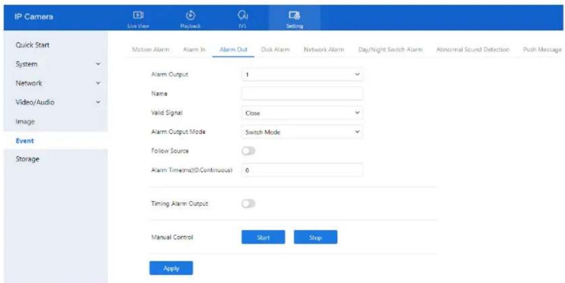
text_image
IP Camera Live View Playback TVS Setting Quick Start System Network Video/Audio Image Event Storage Motion Alarm Alarm In Alarm Out Disk Alarm Network Alarm Day/Night Switch Alarm Abnormal Sound Detection Push Message Alarm Output 1 Name Valid Signal Close Alarm Output Mode Switch Mode Follow Source Alarm Time(ms)(0:Continuous) 0 Timing Alarm Output Manual Control Start Stop ApplyStep 2 Configure the parameters according to Table 7-3.
Table 7-3 Parameters of alarm output
| Parameter | Description | Setting |
| Alarm Output | ID of the alarm output channel. NOTE The number of alarm output channels depends on the device model. | [Setting method] Select a value from the drop-down list box. [Default value] 1 |
| Name | Alarm output channel name. | [Value range] 0 to 32 bytes |
| Valid Signal | The options are as follows: □ Close: An alarm is generated when an external alarm signal is received. □ Open: An alarm is generated when no external alarm signal is received. | [Setting method] Select a value from the drop-down list box. [Default value] Close |
D-Link F-Series Camera User Guide
Configure Event
| Parameter | Description | Setting |
| Alarm Output Mode | When the device receives I/O alarm signals, the device sends the alarm information to an external alarm device in the mode specified by this parameter. The options include the switch mode and pulse mode.NOTEIf the switch mode is used, the alarm frequency of the device must be the same as that of the external alarm device.If the pulse mode is used, the alarm frequency of the external alarm device can be configured. | [Setting method]Select a value from the drop-down list box.[Default value]Switch Mode |
| Follow Source | Alarm output follows the duration of the alarm source. | [Setting method]Enable[Default value]OFF |
| Alarm Time (ms) (0: Continuous) | The status of alarm in is on.Alarm output duration. The value 0 indicates that the alarm remains valid. | [Setting method]Enter a value manually.[Default value]0[Value range]0 to 86400 seconds |
| Timing Alarm Output | Enable timing alarm output, set the schedule to time alarm.NOTEIf there are two alarm outputs, this setting is only valid for Alarm output 1. | [Setting method]Enable[Default value]OFF |
| Manual Control | Control the alarm output. | N/A |
Step 3 Click Apply. If "Apply success!" appears, the settings have been saved successfully.
7.7 Disk Alarm
Procedure
Step 1 Navigate to Setting > Event > Disk Alarm.
The Disk Alarm page is displayed, as shown in Figure 7-6.
D-Link F-Series Camera User Guide Configure Event
Figure 7-6 Disk alarm page

text_image
IP Camera Live View Playback INS Setting Quick Start Motion Alarm Alarm In Alarm Out Disk Alarm Network Alarm Day/Night Switch Alarm Abnormal Sound Detection Push Message System Disk Full Alarm Network Video/Audio Alarm Interval 10 (10-85400)E Output Channel 1 Event Apply StorageStep 2 Click the toggle button on to enable disk alarm.
Step 3 Configure the Alarm Interval. This sets how often the system triggers alarms for disk issues. Enter a value in seconds (range: 10–86400).
Step 4 Select the Out Channel number (Please refer to the actual product).
Step 5 Click Apply. When the message "Apply success!" appears, the configuration is saved.
7.8 Network Alarm
Procedure
Step 1 Navigate to Setting > Event > Network Alarm. The Network Alarm page is displayed, as shown in Figure 7-7.
Figure 7-7 Network alarm page
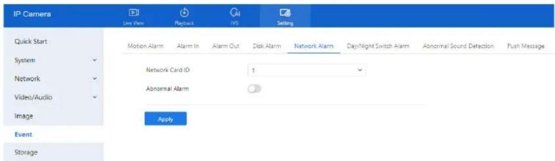
text_image
IP Camera Live View Playback IVS Setting Quick Start Motion Alarm Alarm In Alarm Out Disk Alarm Network Alarm Day/Night Switch Alarm Abnormal Sound Detection Push Message System Network Video/Audio Network Card ID 1 Abnormal Alarm Image Apply Event StorageStep 2 Click the toggle button to enable Abnormal Alarm. The system will monitor the network interface for abnormalities.
Step 3 Configure the Network Alarm Interval. Enter how frequently the system should check for network errors.
Step 4 Select the Output Channel for alarm notifications. You may also enable Alarm Record if an SD card is installed.
Step 5 Click Apply. A message stating "Apply success!" conforms that settings have been saved.
7.9 Day/Night Switch Alarm
Description
The Day/Night Switch Alarm function triggers an alert whenever the camera switches between day and night modes according to the defined schedule.
D-Link F-Series Camera User Guide Configure Event
Procedure
Step 1 Navigate to Setting > Event > Day/Night Switch Alarm. The Day/Night Switch Alarm page is displayed, as shown in Figure 7-8.
Figure 7-8 Day/Night switch alarm
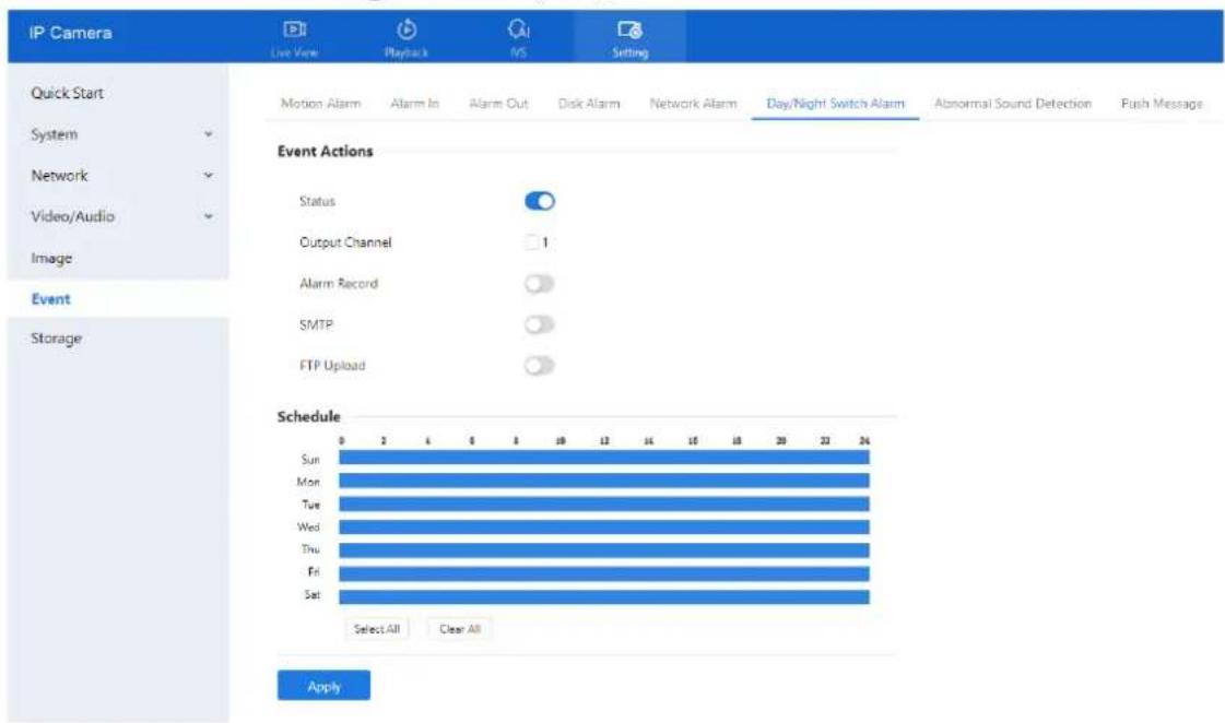
text_image
IP Camera Live View Playback INS Setting Quick Start System Network Video/Audio Image Event Storage Motion Alarm Alarm In Alarm Out Disk Alarm Network Alarm Day/Night Switch Alarm Abnormal Sound Detection Push Message Event Actions Status Output Channel 1 Alarm Record SMTP FTP Upload Schedule Sun Mon Tue Wed Thu Fri Sat Select All Clear All ApplyStep 2 Click the toggle to enable Day/Night Switch Alarm.
Step 3 Configure the alarm schedule.
Define the specific time ranges during which the alarm should be active.
Step 4 Enable Alarm Record if you want the event recorded to an SD card.
Toggle the switch to activate.
Step 5 Enable SMTP if you wish to receive an email notification.
SMTP must be configured under Network > Advanced Settings > SMTP.
Step 6 Enable FTP Upload to send alarm data to an FTP server.
FTP must be pre-configured in system settings.
Step 7 Click Apply.
When the message "Apply success!" appears, the settings are successfully saved.
7.10 Abnormal Sound Detection (Only for Some Models)
Description
The camera is equipped with a built-in microphone or supports external audio input (Line In). On the Audio Abnormal Detection page, you can perform the following actions:
- Enable the Abnormal Sound Detection function.
- Set the schedule during which abnormal sound detection is active.
- Configure the alarm output channel for abnormal sound events.
When this function is enabled and a sudden rise or drop in audio levels is detected during the scheduled time, the camera triggers an alarm and executes the corresponding linkage actions.
D-Link F-Series Camera User Guide
Configure Event
Procedure
Step 1 Navigate to Setting > Event > Abnormal Sound Detection. The Audio Abnormal Detection page is displayed, as shown in Figure 7-9.
Figure 7-9 Audio abnormal detection page
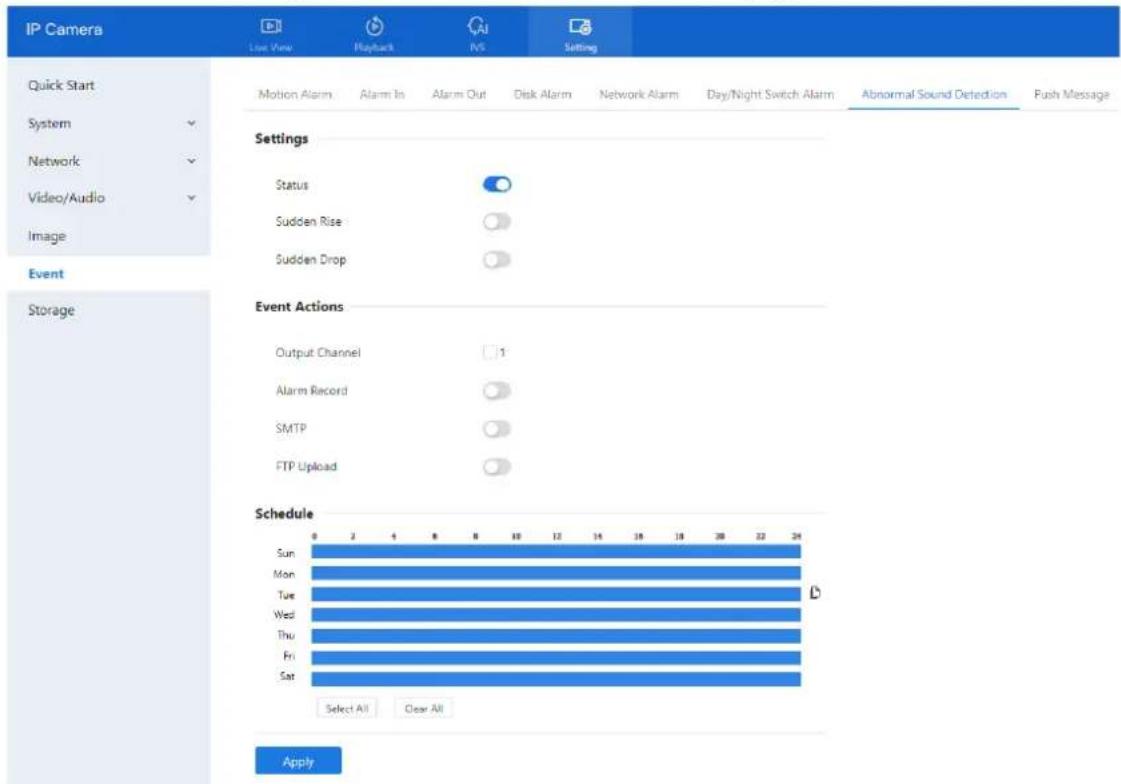
text_image
IP Camera Live View Playback IVS Setting Quick Start System Network Video/Audio Image Event Storage Motion Alarm Alarm In Alarm Out Disk Alarm Network Alarm Day/Night Switch Alarm Abnormal Sound Detection Push Message Settings Status Sudden Rise Sudden Drop Event Actions Output Channel 1 Alarm Record SMTP FTP Upload Schedule Sun Mon Tue Wed Thu Fri Sat Select All Clear All ApplyStep 2 Click the toggle button to enable Audio Abnormal Detection.
Step 3 Enable either or both of the following:
Sudden Rise — detects sharp increases in sound level.
Sudden Drop — detects sharp decreases in sound level.
Step 4 Select the Output Channel for triggering the external alarm.
Step 5 Click the toggle button on to enable Alarm Record, SMTP, FTP Upload.
Step 6 Configure the Schedule (deployment time). For details about how to set Schedule, please refer to 7.4 Step 4.
7.11 Push Message
Description
When alarms are triggered, a notification can be pushed to the mobile app (if the device is connected to and managed through the app).
Procedure
Step 1 Navigate Setting > Event > Push Message.
The Push Message page is displayed, as shown in Figure 7-10.
D-Link F-Series Camera User Guide Configure Event
Figure 7-10 Push message page
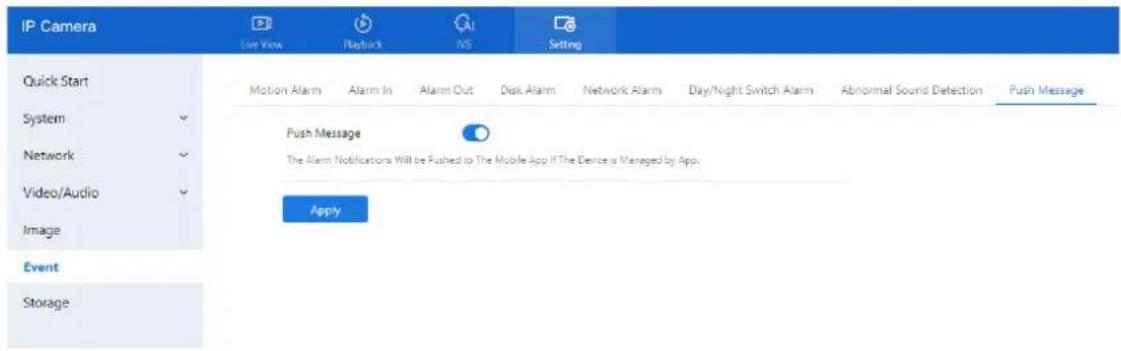
text_image
IP Camera Live View Playback INS Setting Quick Start System Network Video/Audio Image Event Storage Motion Alarm Alarm In Alarm Out Disk Alarm Network Alarm Day/Night Switch Alarm Abnormal Sound Detection Push Message Push Message The Alarm Notifications Will be Pushed to The Mobile App if The Device is Managed by App. ApplyStep 2 Click Apply. A message stating "Apply success!" will confirm the configuration is saved.
7.12 Flashlight Alarm Output (Only for Some Models)
Step 1 Go to Setting > Event > Flashlight Alarm Output interface and set the schedule to enable flashlight alarm, as shown in Figure 7-11.
Figure 7-11 Flashlight alarm page

text_image
IP Camera Line Name Network VS Setting Quick Start System Network Video/Audio Image Event Storage Motion Alarm Alarm It Alarm Out Dual Alarm Network Alarm Daylight Switch Alarm Abnormal Sound Detection Push Messages Flashlight Alarm Output Settings Alarm Time 30 (1-805) Picker Interval 1000 (100-1000/NS) Manual (control duration(S): 0 6-1905 Start Stop Schedule Sun Myn Tue Wed Thu Fri Sat Select All Clear All ApplyStep 2 Configure the Alarm Duration and Flicker Interval.
Step 3 Set the Manual Control Duration:
Click Start to turn on the flashlight manually for the set time.
Click Stop to end the flashlight operation manually.
Step 4 Set the Schedule to determine when the flashlight alarm should be active.
Step 5 Click Apply.
The message "Apply success!" confirms the settings are saved.
7.13 White Light Alarm Output
This alarm requires the Day/Night mode to be set to Night, and the light type to be IR LED or None. When triggered, the camera's white light turns on as part of the alarm response.
D-Link F-Series Camera User Guide Configure Event
Step 1 Navigate to Setting > Event > White light Alarm Output. The White Light Alarm page appears, as shown in Table 8-3.
Figure 7-12 White light alarm page
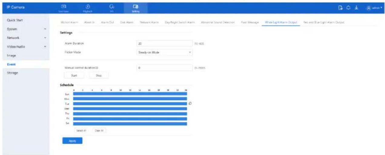
text_image
IP Camera Quick Start System Network Video/Audio Image Event Storage Motion Alarm Alarm In Alarm Out Desk Alarm Network Alarm 日/Night Switch Alarm Abnormal Sound Detection Fuel Message White Light Alarm Output Twe and Blue Light Alarm Output Settings Alarm Duration 20 110-605 Flicker Mode Steady-on Mode Manual control duration(S) 0 (0-70000) Start Stop Schedule Sun Mon Tue Wed Thu Fri Sat Select All Clear All ApplyStep 2 Set the Alarm Duration — the length of time the white light stays on after an alarm is triggered.
Step 3 Set the Deployment Schedule — specify when the white light alarm should be active.
Step 4 Click Apply.
The message "Apply success!" indicates the settings are stored.
7.14 Red and Blue Light Alarm Output
When enabled, the camera flashes alternating red and blue lights upon alarm triggers. This feature is available only on supported models.
Step 1 Navigate to Setting > Event > Red and Blue light Alarm Output. The Red and Blue Light Alarm page appears, as shown in Table 8-3.
Figure 7-13 Red and blue light alarm output page
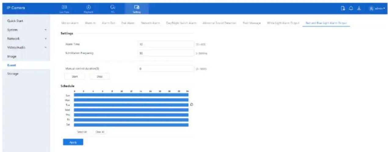
text_image
IP Camera Quick Start System Network Video/Audio Image Event Storage Motion Alarm Alarm In Alarm Out Desk Alarm Network Alarm Copyright Switch Alarm Abnormal Sound Detection Push Message White Light Alarm Output Red and Blue Light Alarm Output Settings Alarm Time 10 15-80E Simulation Frequency 50 0-300ms Manual control duration(S) 0 0-1000s Start Stop Schedule Sun Mon Tue Wed Thu Fri Sat Select All Clear All ApplyStep 2 Set the Alarm Duration — controls how long the lights remain active during an alarm.
Step 3 Choose the Flicker Frequency:
High
Mid
Low
Step 4 Set the Manual Control Duration:
D-Link F-Series Camera User Guide Configure Event
Click Start to activate the alarm manually for the defined duration.
Click Stop to end manual flashing.
Step 5 Define the Deployment Schedule — specify when the red/blue light alarm should be active.
Step 6 Click Apply.
The message "Apply success!" confirms the settings have been saved.
8 Configure Storage Function

NOTE
Some models do not support SD cards. If unsupported, recording functionality will be disabled. Please refer to the specifications of your actual device.
8.4 Record Strategy
You can configure the scheduled recording, alarm recording duration, audio recording, storage rules, and stream selection.
Procedure
Step 1 Navigate to Setting > Storage > Record Strategy.
The Record Strategy page is displayed, as shown in Figure 8-1.
Figure 8-1 Record strategy page

text_image
IP Camera Live View Playback IVS Setting Quick Start Record Strategy Record Directory System ✓ Schedule Record Alarm Post Record® 10 (0-86400)s Record Audio Record Rule Overwrite Stream Name stream1 Storage Sun Mon Tue Wed Thu Fri Sat Select All Clear All ApplyStep 2 Configure the parameters according to Table 8-1.
Table 8-1 Parameters of recording policy
| Parameter | Description | Setting |
| Schedule Record | Enables time-based recording. | [Setting method]Click the button on to enable schedule record.[Default value]OFF |
D-Link F-Series Camera User Guide
Configure Storage Function
| Parameter | Description | Setting |
| Alarm Post Record | Time in seconds to continue recording after an alarm. (0–86400 sec) | [Setting method]Enter a value manually. |
| Record Audio | Records audio along with video. | [Setting method]Click the button on to enable record audio. |
| Record Rule | Rule for saving recordings. The options are as follows:☐Cycle Store:Saves recordings in cycles.☐Save Days:Duration (in days) for saving a recording.The duration can be a maximum of 99999 days.NOTEThe value 0 indicates that recordings are not overwritten. | [Setting method]Select a value from the drop-down list box. |
| Stream Name | Specifies the stream used for recording. | [Setting method]Select a value from the drop-down list box. |
Step 3 Configure the Schedule (deployment time). Refer to section 7.4 Step 4.
Step 4 Click Apply.
If the message "Apply success!" appears, settings are saved successfully.
If other information is displayed, set the parameters correctly.
8.5 Record Directory
Description
Recordings can be saved to an SD Card, FTP, or NAS (Network Attached Storage), depending on your device model.
Procedure
Step 1 Go to Setting > Storage > Record Directory.
The Record Directory page will appear, as shown in Figure 8-2.
D-Link F-Series Camera User Guide Configure Storage Function
Figure 8-2 Record directory page
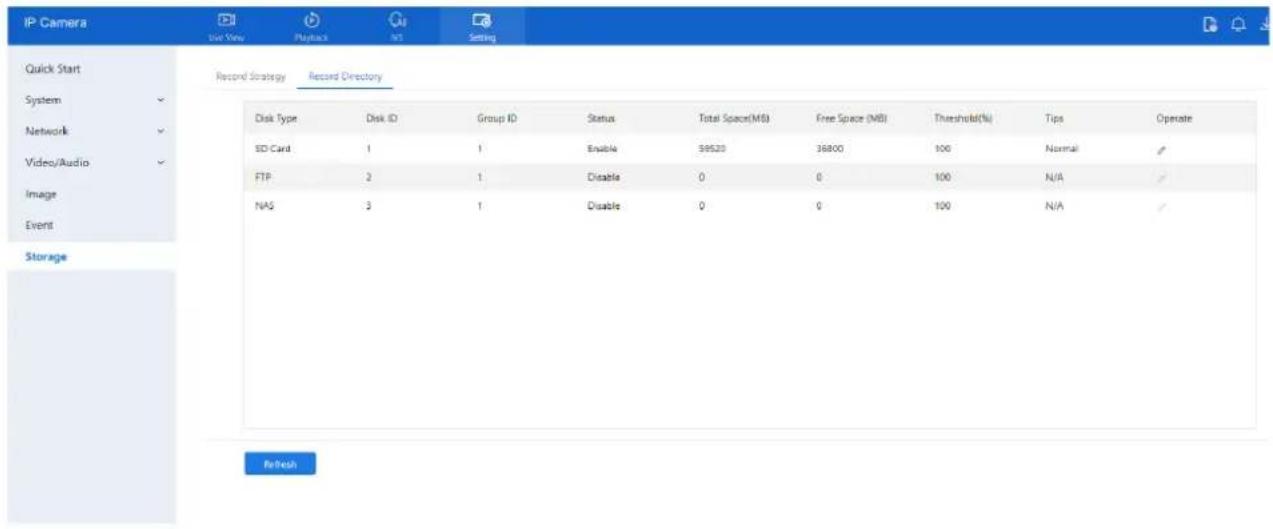
text_image
IP Camera Quick Start System Network Video/Audio Image Event Storage Record Strategy Record Directory Disk Type Disk ID Group ID Status Total Space(MB) Free Space (MB) Threshold(%) Tips Operate SD Card 1 1 Enable 39520 36800 100 Normal ✓ FTP 2 1 Disable 0 0 100 N/A ✓ NAS 3 1 Disable 0 0 100 N/A ✓ RefreshStep 2 Set the parameters according to Table 8-2.
Table 8-2 Parameters of Record directory
| Parameter | Description | Setting |
| Disk Type | Recording device type (e.g., SD card, FTP, NAS). | [Setting method]The parameter cannot be set manually. |
| Disk ID | Identification number of the disk. | |
| Group ID | Group assignment ID. | |
| Enable | Enables selected storage. | |
| Total Space (MB) | Total capacity of the storage device. | |
| Free Space (MB) | Remaining usable space. | |
| Alarm Threshold (%) | Triggers alarm when used space exceeds this threshold. | |
| Status | Shows connection status of the storage device. |
Step 3 Click Modify to update directory parameters.
(See Figure 8-3).
D-Link F-Series Camera User Guide Configure Storage Function
Figure 8-3 Record path modify
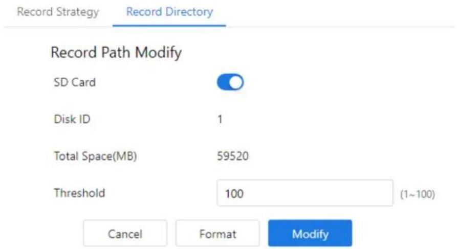
text_image
Record Strategy Record Directory Record Path Modify SD Card Disk ID 1 Total Space(MB) 59520 Threshold 100 (1~100) Cancel Format Modify8.5.2 Configure the SD Card
Procedure
Step 1 Go to Setting > Storage > Record Directory
Step 2 Select SD Card, then click the edit icon.
Step 3 Set parameters as per Table 8-3.
Table 8-3 Parameters of SD card recording
| Parameter | Description | Setting |
| SD Card | Enables SD card recording. | [Setting method]Click button to enable SD card. |
| Disk ID | Identifier of the SD card. | N/A |
| Total Space(MB) | Total disk capacity. | [Setting method]The parameter cannot be set manually. |
| Alarm Threshold (1-100) | Set alert threshold for used space | [Setting method]Enter a value from 1-100. |
Step 4 Click Apply.
Message "Apply success!" confirms the settings are saved.
8.5.3 Configure the FTP
Procedure
Step 1 Step 1: Navigate to Setting > Storage > Record Directory.
Ensure SD card type is OFF.
Step 2 Step 2: Choose FTP and click the edit icon.
The FTP Record Path Modify page appears (see Figure 8-4).
D-Link F-Series Camera User Guide Configure Storage Function
Figure 8-4 FTP record path modify page

text_image
Record Strategy Record Directory Record Path Modify FTP Mode FTP IP Address Port Path (Composed of numbers, letters, and underscores starting with / or \) User Name Password Confirm Total Space(>=512MB) 0 Cancel ModifyStep 3 Set the parameters according to Table 8-4.
Table 8-4 Parameters of FTP recording
| Parameter | Description | Setting |
| FTP | Enables recording to an FTP set | [Setting method]Enable |
| IP Address | IP address of FTP server. | [Setting method]Enter a value manually. |
| Port | Communication port for FTP. | [Setting method]Enter a value manually. |
| Path | FTP Directory path to store recordings. | [Setting method]Enter a value manually. |
| User Name | FTP server account. | [Setting method]Enter a value manually. |
| Password | FTP server password. | [Setting method]Enter a value manually. |
| Confirm | Confirm the password. | [Setting method]Enter a value manually. |
| Free Space (MB) | Available space on FTP server. | [Setting method]Enter a value. |
| FTP over SSL / TLS (FTPS) | Available space on FTP server. | [Setting method]Tick |
D-Link F-Series Camera User Guide
Configure Storage Function
Step 4 Click Apply. A message stating "Apply success!" confirms your settings.
8.5.4 Configure the NAS
Procedure
Step 1 Navigate to Setting > Storage > Record Directory.
Ensure SD card type is OFF.
Step 2 Choose NAS and click the edit icon.
The NAS Record Path Modify page is displayed (see Figure 8-5).
Figure 8-5 NAS record path modify page
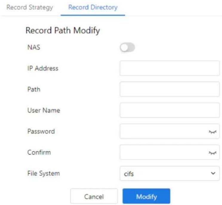
text_image
Record Strategy Record Directory Record Path Modify NAS IP Address Path User Name Password Confirm File System cifs Cancel ModifyStep 3 Set the parameters according to Table 8-5.
Table 8-5 Parameters of NAS recording
| Parameter | Description | Setting |
| NAS | Enables video storage to NAS. | [Setting method]Enable |
| IP Address | IP address of the NAS server. | [Setting method]Enter a value manually. |
| Path | IP address of NAS device. | [Setting method]Enter a value manually. |
| User Name | NAS device account. | [Setting method]Enter a value manually. |
| Password | NAS device Password. | [Setting method]Enter a value manually. |
D-Link F-Series Camera User Guide Configure Storage Function
| Parameter | Description | Setting |
| Confirm | Confirm the password. | [Setting method]Enter a value manually. |
| File System | Choose between CIFS and NFS protocols. | [Setting method]Choose from drop-down list.[Default value]cifs |
Step 4 Click Apply. The message "Apply success!" confirms the settings have been stored.
9.4 Configure AI Multi-Target
Step 1 Navigate to IVS > Deep Learning > AI Multi-Target. The AI Multi-Target to set page is displayed as shown in Figure 9-1.
Figure 9-1 AI Multi-Target page
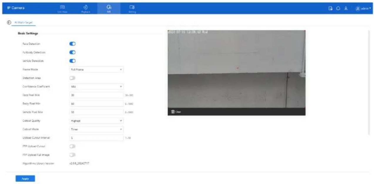
text_image
IP Camera View View Replace NS Setting AI Multi-Target Basic Settings Face Detection FullBody Detection Vehicle Detection Frame Mode: Full Frame Detection Area Confidence Coefficient: Mid Face Pixel Mix: 30 36-390 Body Pixel Min: 50 2-1000 Vehicle Pixel Mix: 50 2-1000 Coutout Quality: Highest Coutout Mode: Timer Upload Cutout Interval: 5 1-10 FTP Upload Cutout FTP Upload Full Image Algorithms Library Version: +2.8.20240717 Apply 2024-09-10 12:38:12 Real ClearTable 9-1 lists the AI Multi-Target parameters.
Table 9-1 Parameters of AI Multi-Target
| Parameter | Description | How to set |
| Face Detection | Enables face capture when a person appears in the live video. | Enable |
| Full body Detection | Enables full-body capture when a person appears. | Enable |
| Vehicle Detection | Captures vehicle when it appears in the video feed. | Enable |
| Frame Mode | Display box style in live view: Full Frame, Four-Corner, Mosaic, or OFF. | Choose from drop list. |
| Detection Area | Shows detection area on the live video feed. | |
| Confidence Coefficient | Sets detection confidence (High, Mid, Low). Higher = better accuracy. | Choose from drop list. |
| Face Pixel Min (30- | Minimum face pixel for capture (30–300). | Input a value |
D-Link F-Series Camera User Guide
IVS Settings
| Parameter | Description | How to set |
| Below this value, faces aren't captured. | range 30 to 300 | |
| Body Pixel Min (30-300) | Minimum full-body pixel for capture (30–300). | Input a value range 30 to 300 |
| Vehicle Pixel Min (30-300) | Minimum vehicle pixel for capture (30–300). | Input a value range 30 to 300 |
| Cutout Quality | Snapshot quality: Low, Mid, High. | Choose from drop list. |
| Cutout Mode | Cutout capture mode: Timing or Optimal. | Choose from drop list. |
| Upload Cutout Interval | Time interval between snapshots in Timing mode (1–10 seconds). | Input a value range 1 to 10 |
| FTP Upload Cutout | Uploads snapshots to FTP (configured under Configuration > Network Service > FTP). | Enable |
| FTP Upload Full Image | Uploads the entire image to FTP. | Enable |
Step 2 Set the deployment schedule. Refer to Section 7.4 Step 4.
Step 3 Click Apply. The message "Apply succeed!" confirms that settings are saved.
9.5 Configure Intelligent Analysis
9.5.1 Intrusion
Description
Generates an alarm when a target (person or vehicle) enters a defined detection area.
Procedure
Step 1 Go to IVS > Intelligent Analysis > Intrusion.
The Intrusion Settings page appears (see Figure 9-2).
Step 2 Set the intrusion parameters as listed below.
D-Link F-Series Camera User Guide IVS Settings
Figure 9-2 Intrusion settings page
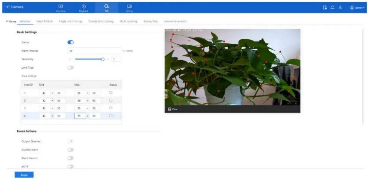
text_image
IP Camera Use View Pooled MS Setting Profile Inhalation Smart Motion Single Line Crossing Double Line Crossing Multi-Lensing Wrong Way General Fertilizers admin* Basic Settings Status Alarm Interval 10 Sensitivity 5 Limit Type Area Settings Area ID Mini Max Status 1 42 50 85 50 2 42 50 85 50 3 42 50 85 50 4 42 50 85 50 Event Actions Output Channel 1 Audible Alarm Alarm Record SMTP ApplyStep 3 Set all parameters of intrusion. Table 9-2 describes the specific parameters.
Table 9-2 Intrusion parameter description
| Parameter | Description | Setting |
| Status | Enables the intrusion alarm. | [How to set]Click the button on.[Default value]OFF |
| Alarm Interval | Time interval (in seconds) during which identical alarms will not be repeated (1–1800s). | [How to set]Input a value, 1~1800s |
| Sensitivity | Higher sensitivity increases detection but reduces accuracy. | [How to set]Choose from the drop-down list[Default value]5 |
| Limit Type | Choose detection target: Person, Car, or Both. | [How to set]Click the button on.[Default value]OFF |
| Area Listings | Set the areas will show in listings. Tick the status, the min and max detecting area show on area, you can drag the point to adjust the size of the detecting area, or modify the value directly. | [How to set]Set the detecting area. |
D-Link F-Series Camera User Guide
IVS Settings
| Parameter | Description | Setting |
| Output Channel | If you check to set the Output Channel and the device is connected to an external alarm indicator, the alarm indicator signals when an alarm is triggered. Only for Some Models. | [How to set]Click to select an ID. |
| Audible Alarm | After enabling Audible Warning and setting Audible Alarm Output, the built-in speaker of the device or connected external speaker plays warning sounds when an alarm happens. (set at the “Setting > Video / Audio > Audio File”). | [How to set]Click to enable Audible alarm [Default value]OFF |
| Alarm Record | The device will record alarm with SD card. | [How to set]Click to enable alarm record. [Default value]OFF |
| SMTP | Enable the button to enable SMTP serve. | [How to set]Click to enable SMTP. [Default value]OFF |
| FTP Upload | Enable the button to enable File Transfer Protocol. | [How to set]Click to enable FTP Upload. [Default value]OFF |
| Flashlight Alarm | After enabling Flashing Light and setting the Flashing Light Alarm Output, the light flashes when an alarm event is detected. | [How to set]Click the button on. [Default value]OFF |
| White light Alarm | When the Day/Night mode is chosen Night mode, and the light is IR LED or NONE, this linkage action is valid. Enable to white light alarm when it triggers the alarm, the white light will be on. Only for Some Models. | [How to set]Click the button on. [Default value]OFF |
D-Link F-Series Camera User Guide IVS Settings
| Parameter | Description | Setting |
| Red and Blue Light Alarm | The camera should have red and blue light.When an alarm occurs, the device will flicker alternating red light and blue light. | [Setting method]Enable Red and Blue Light Alarm[Default value]OFF |
Step 4 Set a deployment area.
To configure the detection area:
Step 1 Move the cursor to the drawing interface.
Step 2 Click to create a point—this marks the starting vertex of the area.
Step 3 Move the cursor and click again to create the next point, forming a line segment.
Step 4 Repeat this process to form a polygon that outlines the detection area.
Step 5 Once your shape is complete, right-click to finish the drawing.
Note:
• Lines cannot intersect each other.
• Each shape can have up to 8 sides.
• You can draw up to 8 separate detection areas.
See Figure 9-3 for a visual reference of the drawing interface.
Figure 9-3 Deployment area setting page
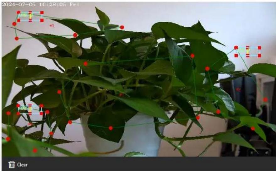
text_image
2024-07-05 10:28:05 Fri MIN 1 #3 MIN 1 Clear9.5.2 Smart Motion
Description
Smart motion detection generates an alarm when specified target objects—such as people, vehicles, or both—move within a predefined area.
Procedure
Step 1 Go to IVS > Intelligent Analysis > Smart Motion. The Smart Motion settings page appears as shown in Figure 9-4.
Figure 9-4 Smart motion settings page
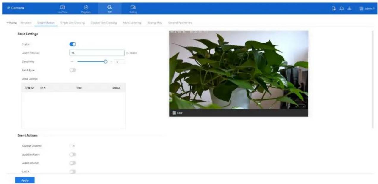
text_image
IP Camera Use View Playback NE Setting IP-Home Integration Smart Motion Single Line Crossing Double Line Crossing Multi-Litering Wrong-Play General Parameters Basic Settings Status Alarm Interval 10 Sensitivity 3 Limit Type Area Settings Area ID Min Max Status Event Actions Output Channel 1 Audible Alarm Alarm Record SMTP ApplyStep 2 Configure all parameters. Refer to section 9.5.1 Step 3 for details
Step 3 Define the detection area:
- Move the cursor to the live view.
- Click to place the first point.
- Continue clicking to form a polygonal area.
• Right-click to finish drawing.

NOTE
• Lines must not intersect.
• You can draw a shape with up to 8 sides.
- You can define up to 8 deployment areas.
Step 4 Set the deployment time. Refer to 7.4 Step 4.
Step 5 Click Apply. A message "Apply success!" will confirm that the settings have been saved.
D-Link F-Series Camera User Guide
IVS Settings
9.5.3 Single Line Crossing
Description
Single line crossing detection monitors a virtual line placed in the camera's field of view. An alarm is triggered when a target (such as a person or vehicle) crosses the line in a specified direction.
Procedure
Step 1 Go to IVS > Intelligent Analysis > Single Line Crossing.
The Single Line Crossing settings page appears, as shown in Figure 9-5.
Figure 9-5 Single line crossing setting interface

text_image
IP Cameras Live Now Reply NS Setting Home Intrusion Smart Motion Single Line Crossing Double Line Crossing Multi-Labeling Wrong -Play Glasses Paramount Basic Settings Status Alarm Interval 10 11~1820% Limit Type Type: Pencil or Car Event Actions Output Channel Audible Alarm Alarm Record SMTP FTP Upload Schedule Sun Mon Tue Wed Thu Fri Sat ApplyStep 2 Set all parameters of the single line crossing, please refer to 9.5.1 Step 3.
Step 3 Draw and configure the crossing line:
- Hold down the left mouse button and draw a straight line.
- Release the button to create the single line crossing.
- Click the line to select it (it turns red when selected).
- Set the direction: Positive, Reverse, or Bidirectional.
• To reposition the line, drag from either endpoint.
• Right-click to delete the line, as shown in Figure 9-6.
D-Link F-Series Camera User Guide IVS Settings
Figure 9-6 Deployment area setting page
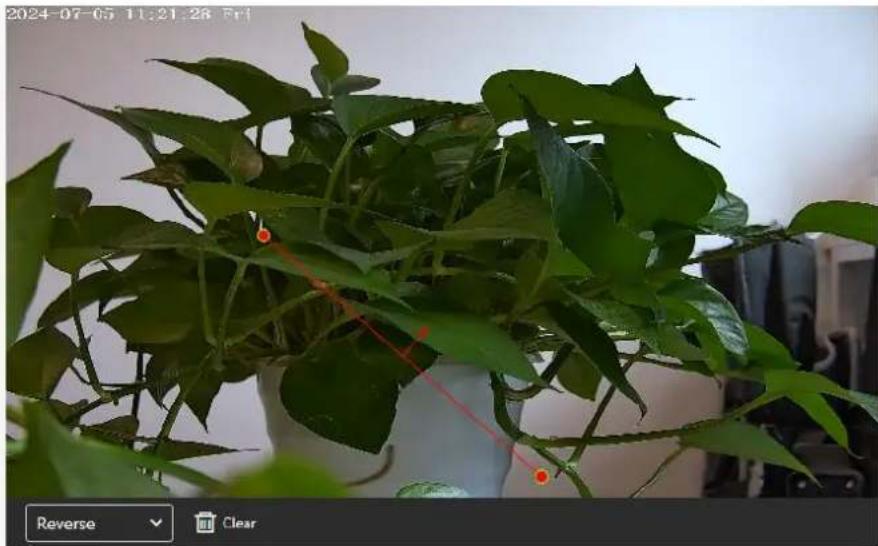
natural_image
Potted plant with green leaves and red measurement lines, displayed in a white vase (no text or symbols on the plant itself)
NOTE
- Draw the line toward the center of the screen for better recognition timing. - Ensure the line is long enough short lines may miss detection, especially for targets recognized by foot position.
Step 4 Set the deployment time. Refer to section 7.4 Step 4.
Step 5 Click Apply. A message "Apply success!" will confirm that the settings have been saved.
9.5.4 Double Line Crossing
Description
Double line crossing defines two virtual lines in the monitored area. An alarm is triggered when a target (such as a person or vehicle) crosses both lines in a specific direction and order—first Line 1, then Line 2—within a predefined time frame.
Procedure
Step 1 Navigate to IVS > Intelligent Analysis > Double Line Crossing to access the Double Line Crossing setting interface, as shown in Figure 9-7.
D-Link F-Series Camera User Guide IVS Settings
Figure 9-7 Double line crossing settings interface
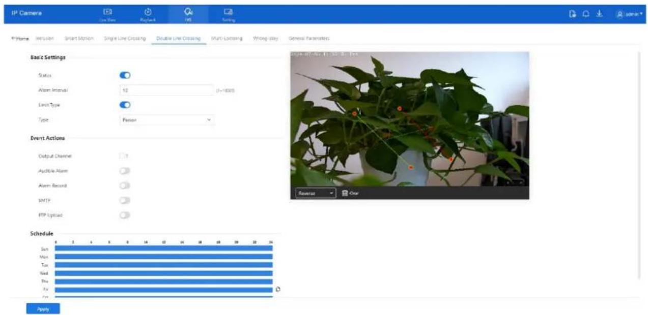
text_image
IP Camera Line Trace MapNet INS Setting F:\Home Inclusion Smart Motion Single Line Crossing Double Line Crossing Multi-Licensing Wrong-Play General Parameters Basic Settings Status Atom Interval: 10 (1~1800) Limit Type Type: Person Event Actions Output Channel: 7 Audible Alarm: Alarm Record: SMTP: FTP Upload: Schedule Sun Max Tue Wed Thu Fri ApplyStep 2 Set all parameters of the double line crossing, please refer to 9.5.1 Step 3. Define the deployment area.
- Drawing lines: Hold down the left mouse button and draw two lines in sequence. Release to generate two virtual fences labeled "1" and "2."
- Setting direction: Click on either fence (it will turn red when selected). Choose Positive or Reverse direction from the drop-down.
- Editing lines: Drag the endpoints to adjust the size or position. Right-click to delete a line, as shown in Figure 9-8.
Figure 9-8 Deployment area settings page
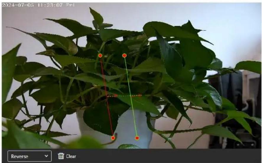
text_image
2024-07-05 11:23:07 3:11 Reverse ClearD-Link F-Series Camera User Guide IVS Settings

NOTE
☐ The system recognizes a valid crossing only if Virtual Fence 1 is crossed before Virtual Fence 2.
☐ Draw the fences toward the center of the screen to ensure the target is fully recognized before crossing.
☐ The fence length must be sufficient for reliable foot-based detection.
☐ Direction cannot be manually adjusted other than by selecting Reverse.
Step 3 Set the deployment time. Refer to Section 7.4 Step 4.
Step 4 Click Apply. A message saying "Apply success!" confirms that the settings have been saved.
9.5.5 Multi-Loitering
Description
Multi-loitering detection triggers an alarm when multiple targets (e.g., persons or vehicles) remain in a defined area longer than a specified minimum loitering time.
Procedure
Step 1 Navigate to IVS > Intelligent Analysis > Multi-Loitering to access the Multi-Loitering setting interface, as shown in Figure 9-9.
Figure 9-9 Multi-Loitering setting page

text_image
IP Camera Line Item Playback VS Setting 4-Home Inclusion Smart Motion Single Line Crossing Double Line Crossing Multi-Linking Wrong-Wig General Parameters Basic Settings Status Alarm Interval: 10 (1-1800) The Shortest Time: 10 (5-65) Limit Numbers: Minimum Number: 1 Area Listings Area ID Min Max Status 1 42 30 85 50 Event Actions Output Channel: 1 Audible Alarm: Alarm Record: ApplyStep 2 Set all parameters of multi-loitering, please refer to 9.5.1 Step 3.
Step 3 Set a deployment area:
- Move the cursor and click to define points.
- Click again to add vertices and create a polygon.
• Right-click to complete the shape, as shown in Figure 9-10.
D-Link F-Series Camera User Guide IVS Settings
Figure 9-10 Deployment area settings page
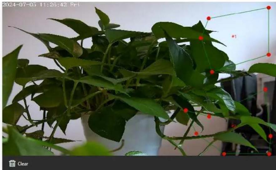
natural_image
Potted plant with green leaves and red dots, displayed indoors (no text or symbols visible)
NOTE
• A Lines cannot cross each other.
- You may define up to 8-sided shapes.
• A maximum of 8 deployment areas is supported.
Step 4 Set the deployment time. Refer to section 7.4 Step 4.
Step 5 Click Apply. The he system will save the configuration and display "Apply success!
9.5.6 Wrong-Way
Description
Wrong-Way monitors directional movement within a designated area. An alarm is triggered when a target (such as a person or vehicle) moves in the opposite direction of the configured travel path.
Procedure
Step 1 Navigate to IVS > Intelligent Analysis > Wrong-Way to access the Wrong-Way settings interface, as shown in Figure 9-11.
D-Link F-Series Camera User Guide IVS Settings
Figure 9-11 Wrong-Way settings page
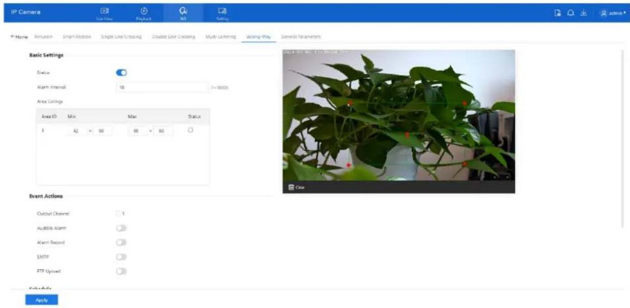
text_image
IP Camera Line View PlayBack NS Setting Home Invasion Smart Motion Single Line Crossing Double Line Crossing Multi-Lathering Wrong Play General Parameters Basic Settings Status Alarm Interval 10 1=16006 Area Listings Area ID Min Max Status 1 42 × 50 88 × 90 Event Actions Output Channel 1 Audience Alarm Alarm Record SMTP FTP Uplowd ApplyStep 2 Set all parameters of Wrong-Way, please refer to 9.5.1 Step 3.
Step 3 Define the deployment area.
- Move the cursor on the video interface and click to create a point.
- Continue clicking to form lines and enclose a custom shape.
• Right-click to finish the area drawing. - Use the arrow tool within the field to define the reverse direction of travel, as shown in Figure 9-12.
Figure 9-12 Deployment area setting interface

natural_image
Potted plant with green leaves and red markers, captured on 2024-07-05 at 11:39:30 (no text or symbols on the plant itself)
NOTE
• Lines must not intersect, or the drawing will fail.
• A maximum of 8 sides per shape and up to 8 zones are supported.
Step 4 Set deployment time, please refer to 7.4 Step 4.
Step 5 Click Apply. The system will save your settings and display the message "Apply success!".
D-Link F-Series Camera User Guide IVS Settings
9.6 Configure People Counting
9.6.1 Setting
People Counting allows the camera to count entries and exits across a defined line in the monitored area. This is useful for analyzing foot traffic.
Procedure
Step 1 Navigate to IVS > Behavior Analysis > People Counting to access the People Counting setting interface, as shown in Figure 9-13.
Figure 9-13 People counting page

text_image
IP Camera Use View Products No. Settings P-Home: Paragle Counting Set Request Basic Settings Status GSD Enable Counting Clear Interval 10Day Clear Area Type Line A→B Out B→A In Set Correction Value Threshold Alarms Event Actions Output Channel 1 Audible Alarm Alarm Record SMTP ApplyStep 2 Set all parameters of illegal parking. Table 9-3 describes the specific parameters.
Table 9-3 Parameters of people counting
| Parameter | Description | Setting |
| Mode (only for PTZ camera) | Choose between Normal and Preset Point mode. Preset mode requires selecting a predefined point. | [How to set]Choose from the drop-down list[Default value]Normal mode |
| Enable | Enables the button to enable the alarm. | [How to set]Click the button on.[Default value]OFF |
D-Link F-Series Camera User Guide
IVS Settings
| Parameter | Description | Setting |
| OSD Enable | Enable the OSD, the count data will show on live video screen. | [How to set]Click the button on.[Default value]OFF |
| Counting Clear Interval | Automatically resets the count at set intervals (e.g., 10 min, 1 hour, etc.). Manual reset also available viaClear Counting. | [How to set]Choose from drop-down list.[Default value]12 hours |
| Area Type | Defines the counting method (e.g., line). Labels A and B indicate "In" and "Out." | [How to set]Choose from drop-down list.[Default value]Line |
| Set Correction Value | Enable, set the count correction value, it can be positive or negative. For example, if there are 30 people enter the area before counting, input 30 to correct. If 30 people go out the area, input -30. | [How to set]Enable /Input a value in the area box.[Default value]0 |
| Threshold alarm | Triggers an alarm if the count exceeds a defined threshold. | [How to set]Click the button on.[Default value]OFF |
| Output Channel | If you click to set the Output Channel and the device is connected to an external alarm indicator, the alarm indicator signals when an alarm is triggered. Only for Some Models. | [How to set]Click to select an ID. |
| Flashlight Alarm | After enabling Flashing Light and setting the Flashing Light Alarm Output, the light flashes when an alarm event is detected.Only for Some Models. | [How to set]Click the button on.[Default value]OFF |
D-Link F-Series Camera User Guide
IVS Settings
| Parameter | Description | Setting |
| Audible Alarm | After enabling Audible Warning and setting Audible Alarm Output, the built-in speaker of the device or connected external speaker plays warning sounds when an alarm happens. (set at the “Setting > Video / Audio > Audio File”) Only for some models. | [How to set]Click the button on.[Default value]OFF |
| Alarm Record | Enable the button to enable the alarm record. | [How to set]Click to enable Alarm Record.[Default value]OFF |
| SMTP | Enable the button to enable SMTP sever.The parameters of SMTP can be set at Setting > Network > Advanced Settings > SMTP interface. | [How to set]Click to enable SMTP.[Default value]OFF |
| FTP Upload | Enable the button to enable File Transfer Protocol.The parameters of FTP can be set at Setting > Network > Advanced Settings > FTP interface. | [How to set]Click to enable FTP Upload.[Default value]OFF |
| White light Alarm | When the Day/Night mode is chosen Night mode, and the light is IR LED or NONE, this linkage action is valid.Enable to white light alarm when it triggers the alarm, the white light will be on. Only for Some Models. | [How to set]Click the button on.[Default value]OFF |
Step 3 Set the deployment area:
- Click to generate points on the live video screen.
- Continue to form a line or shape.
• Right-click to finish drawing.
Step 4 Set the deployment time. Refer to section 7.4 Step 4.
Step 5 Click Apply. The system saves your configuration and confirms with "Apply success!".
9.6.2 Report
The People Counting interface allows you to view statistical data by setting specific query conditions, including a defined time range. The data can be visualized in three formats: Line Chart, Histogram, or List, as shown in Figure 9-14.
D-Link F-Series Camera User Guide IVS Settings
Figure 9-14 People counting page
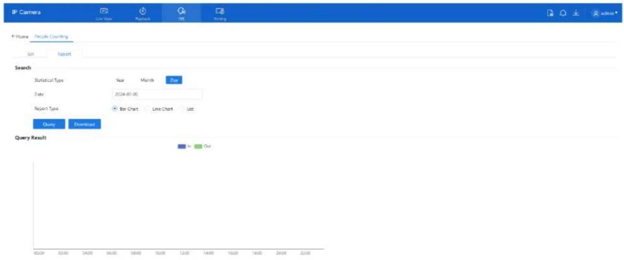
text_image
IP Camera Live View Products INS Ranking Home People Counting Set Report Search Statistical Type Year Month Our Date 2024-07-05 Report1 Type Bar Chart Line Chart List Query Download Query Result in OutProcedure
Step 1 Set the Time Range:
- Use the calendar pop-up to select the Start and End time for the query.
- Select the Year and Month as needed.
Step 2 Choose Report Type:
○ Available display formats include:
- Line Chart
- Histogram
- List
Step 3 Query the Data:
- Click the Query button to retrieve the people counting results based on the specified conditions.
Step 4 Download Results:
- Click Download to export the query results. The data can be saved to a local folder for further analysis or reporting.
10.4 Configure PTZ
10.4.1 Control and Configure the PTZ (Only for Some Models)
Description
PTZ (Pan-Tilt-Zoom) functions are supported on high-speed network domes, PTZ cameras, or cameras connected to an external PTZ device. Motorized cameras also support focus and zoom actions. Please refer to the actual product for available features.
Controlling the PTZ
When browsing real-time videos of a dome camera or a camera connected to an external PTZ, you can control the PTZ to view videos in different directions.
Click PTZ below the Live Video page to open the PTZ Control page as shown in Figure 10-1, you can click the eight arrow keys to move the PTZ in eight directions. You can also zoom the lens and adjust the focal length.
Figure 10-1 PTZ control area
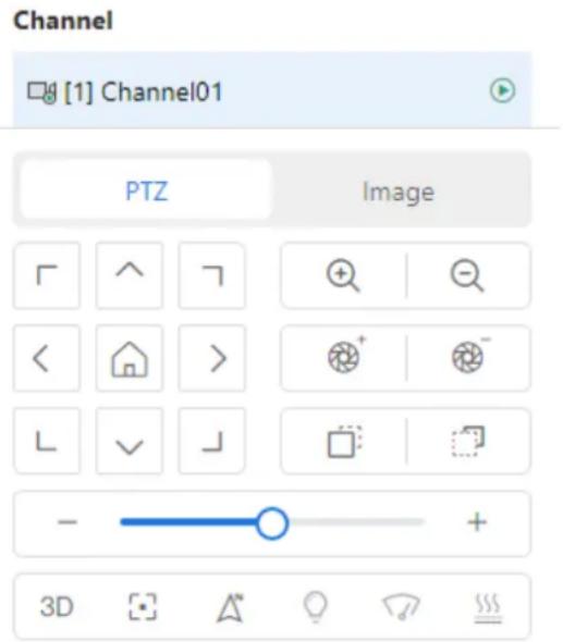
text_image
Channel [1] Channel01 PTZ Image 3DIn the PTZ control area, you can perform the following operations:
☐ Slide the slider left or right beyond the PTZ rotation keys, you can adjust the PTZ rotation speed.
☐ Click the arrows to move the PTZ in eight directions.
□ Click to go home position.
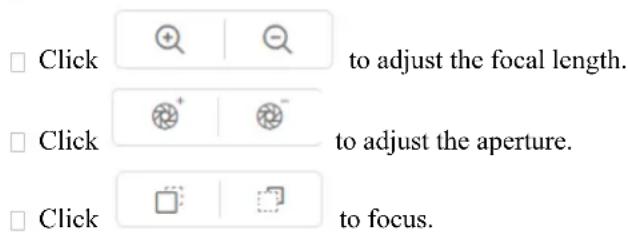
text_image
Click to adjust the focal length. Click to adjust the aperture. Click to focus.
text_image
Click to adjust the focal length.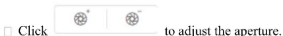
text_image
Click to adjust the aperture.
D-Link F-Series Camera User Guide
PTZ
☐ Click △ to set north direction. You can define any direction as due north as the reference point of the PTZ rotation.
Click to operate the lens directly, zoom +/zoom- the area, or move the focus point. The 3D positioning function quickly rotates the PTZ and changes the focal length in specific scenarios. You can also change the focus by drawing rectangle frames.
□
□ Click ☐ to enable automatic focus.
You can set light On/Off, brush function and reboot action in extension page. There are heating and defogging applicable for some special cameras.
Click to enable the light. Light On/Off is used to control the infrared camera shields on and off.
Click to enable brush. Brush is used to clean the lens.
Click to start heat lens to defog, click again to end.

NOTE
- Brush is available only to a camera with a brush or a camera shield.
• Light On/Off is available only to specific camera shields.
10.4.2 Configure the PTZ
It is available for the cameras with PTZ or connected to PTZ. PTZ Configure interface is as shown in Figure 10-2.
Figure 10-2 PTZ configure area
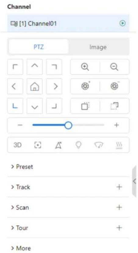
text_image
Channel [1] Channel01 PTZ Image > Preset > Track > Scan > Tour > MoreIn the PTZ configure area, you can perform the following operations:
D-Link F-Series Camera User Guide
PTZ
☐ Add, delete, and invoke preset positions.
☐ Add, delete, and invoke tracks.
☐ Add, delete, and invoke scans.
☐ Add, delete, and invoke tours.
□ Set the home.
□ Set the idle.
□ Set the timer.
☐ Set the extension. Set Light On/Off and Brush function.
Brush is used to clean the lens. Light On/Off is used to control the infrared camera shields on and off.

NOTE
Brush is available only for a camera with a brush or a camera shield.
Light On/Off is available only for specific camera shields.
10.4.3 Configure and Invoke Home / Preset Positions
You can configure preset positions and quickly rotate the camera to a preset position by invoking the preset position.
Choose setting > PTZ > Preset. You can set preset and home position at preset interface
Figure 10-3 Preset interface

text_image
IP Camera Quick Start System Network Video/Audio Image PTZ Event Storage Reset Track Scan Tour Idle Timer Power-Up Action Intelligent Training Dome PTZ Home Setting Set Restore Preset Management 3 Total / 400 Max Remove All ID Name Optimize 1 Preset 1 2 Preset 2 3 Preset 3 4 Preset 4 5 Preset 5 6 Preset 6 7 Preset 7 8 Preset 8 9 Preset 9 2024-07-12 08:00:00:00:00:00:00:00:00:00:00:00:00:00:00:00:00:00:00:00:00:00:00:00:00:00:00:00:00:00:00:00:00:00:00: F G H I J K L M N O P Q R S T U V W X Y Z Z' Z' Z' Z' Z' Z' Z' Z' Z' Z' Z' Z' Z' Z' Z' Z' Z' Z' Z' Z' Z' Z' Z' Z' Z' Z' Z' Z' Z' Z' Z' Z' Z' Z' Z' Z' Z' Z' Z' Z' Z' Z' Z' Z' Z' Z' Z' Z' Z' Z' Z'D-Link F-Series Camera User Guide PTZ
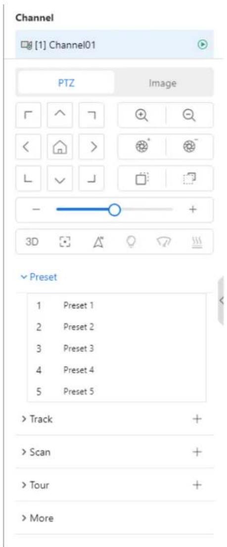
text_image
Channel [1] Channel01 PTZ Image ✓ Preset 1 Preset 1 2 Preset 2 3 Preset 3 4 Preset 4 5 Preset 5 > Track > Scan > Tour > MoreYou can set any point as Home and the default Home is the 0.00/90.0/1X coordinate. Click go home position directly.

Step 1 Click Home.
The Home setting page is displayed as shown in Figure 10-4.
Figure 10-4 Home configuration
Home Setting

Step 2 Adjust the PTZ keyboard to operate the lens.
Step 3 Click Set to set home. Click Restore to restore the default home.
Step 4 Click invoke home.
Step 1 Configure a preset position.
D-Link F-Series Camera User Guide
PTZ
- Choose the preset ID.
- Adjust the direction of PTZ to finish the preset position setting.
- Click to save, click to rename.
- Click to delete the current preset.
Step 2 Invoke a preset position.
Select a preset position from the Preset list to invoke the preset position. Click → icon to invoke.

NOTE
The special presets:
- Set No.64 preset, the PTZ functions restore to factory settings.
- Invoke No.92 preset, set the start point of scan.
- Invoke No.93 preset, set the end point of scan.
- Invoke No.97 preset, it will invoke the SCAN 1.
- Set No.97 preset, view the version of MCU and chip.
- Invoke No.99 preset, scan by rotating 360°.
- Invoke No.250 preset, enable the MCU temperature.
- Invoke No.251 preset, disable the MCU temperature.
- Set No.252 preset, the PTZ parameters will be restore to factory settings.
- Invoke 103 preset, the brush works once, this function is only for PTZ cameras with brush.
10.4.4 Configure and Invoke Tracks
You can record a track to allow the camera to repeatedly rotate based on the preset track.
Step 1 Configure a track.
- Set the track ID and name.
- Click Start to set the starting position of the track.
- Use arrow keys in the PTZ Control area to set a required a track.
- Click End to finish the track setting.
Figure 10-5 Track configuration

text_image
Add Track ID 2 Name Track 2 Start End Scan Management 1 Total / 6 Max Remove All ID Name Operate 1 Track 1 2 Track 2 3 Track 3 4 Track 4 5 Track 5 6 Track 6 2024-07-11 09:32:13 Thur 180.48/27.47/1.0x S STOP SET TRACK 1 30D-Link F-Series Camera User Guide
PTZ
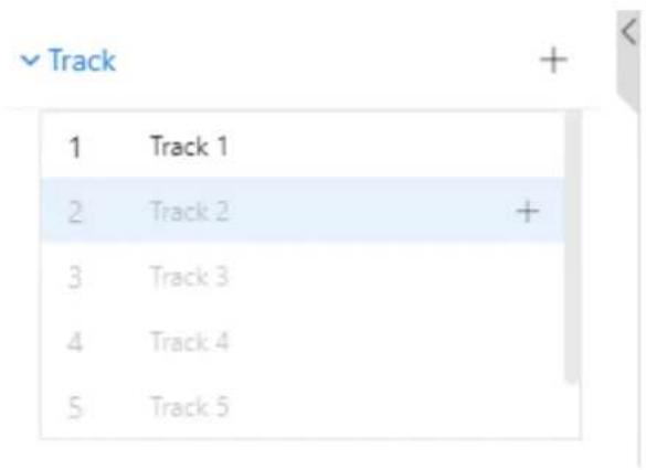
text_image
Track 1 Track 1 2 Track 2 + 3 Track 3 4 Track 4 5 Track 5Step 2 Invoke a track.
Select a track name from the Track list, click to invoke the track.
Click to delete the current track. Or click Remove All to delete all track.

NOTE
A maximum of six tracks can be configured.
10.4.5 Configure and Invoke Scans
You can configure a starting point and end point to allow the camera to repeatedly rotate from the starting point to end point.
Step 1 Configure a scan.
- Click Scan.
The Scan Add page is displayed as shown in Figure 10-6.
Figure 10-6 Scan configuration
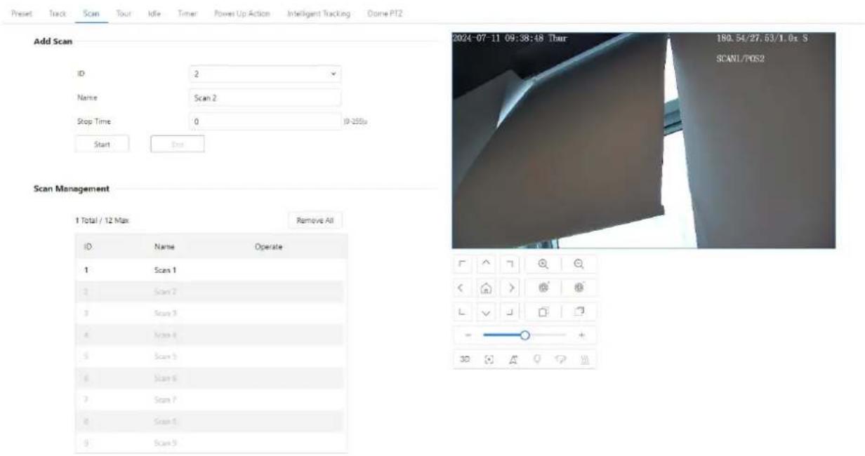
text_image
Add Scan ID 2 Name Scan 2 Stop Time 0 ID-255u Start Bus Scan Management 1 Total / 12 Max Remove All ID Name Operate 1 Scan 1 2 Scan 2 3 Scan 3 4 Scan 4 5 Scan 5 6 Scan 6 7 Scan 7 8 Scan 8 9 Scan 9 2024-07-11 09:38:48 Thur 180.64/27.63/1.0x S SCANL/PDS2D-Link F-Series Camera User Guide
PTZ
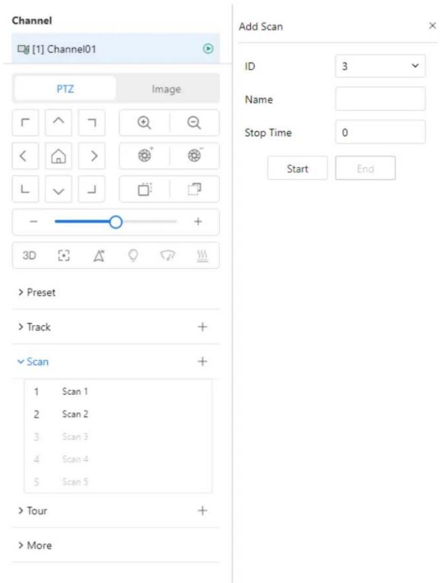
text_image
Channel [1] Channel01 PTZ Image Add Scan ID 3 Name Stop Time 0 Start End > Preset > Track + ✓ Scan + 1 Scan 1 2 Scan 2 3 Scan 3 4 Scan 4 5 Scan 5 > Tour + > More- Set the scan ID and name.
- Click Start to start setting.
- Use arrow keys in the PTZ Control area to set a start point and an end point.
- Click End to finish the scan setting.
Step 2 Invoke a scan.
Select a scan value from the Scan list box, click to invoke the scan.
Click to delete the current scan.

NOTE
A maximum of twelve scans can be configured.
10.4.6 Configure and Invoke Tours
You can configure a tour to allow the camera to repeatedly rotate based the tours. Each tour includes presets and wait time should be set.
Step 1 Configure a tour.
- Click Tour.
The Tour Add page is displayed as shown in Figure 10-7.
D-Link F-Series Camera User Guide
PTZ
Figure 10-7 Tour configuration
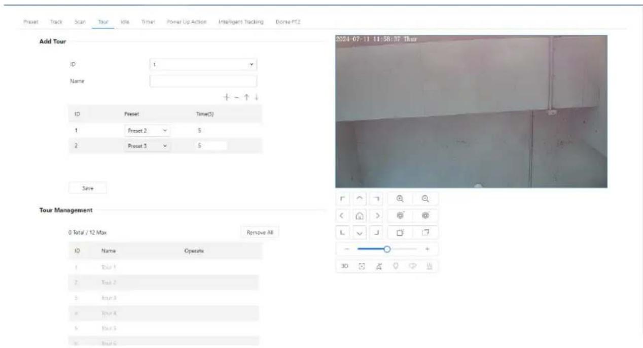
text_image
Add Tour ID 1 Name + - ↑↓ ID Preset Time(5) 1 Preset 2 5 2 Preset 3 5 Save Tour Management 0 Total / 12 Max Remove All ID Name Operate 1 Trail 1 2 Trail 2 3 Trail 3 4 Trail 4 5 Trail 5 6 Trail 6 2024-07-11 11:58:37 Thur L V J + 30D-Link F-Series Camera User Guide
PTZ
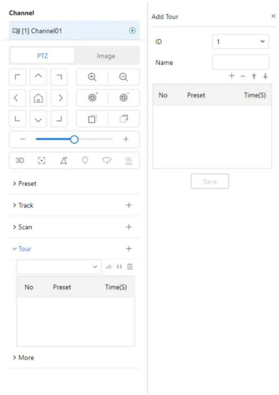
text_image
Channel [1] Channel01 PTZ Image Add Tour ID 1 Name + - ↑↓ No Preset Time(S) > Preset > Track + > Scan + Tour + No Preset Time(S) > More- Set the tour ID and name.
- Click + to start add preset to tour.
- Select a preset and set the wait time.
- Continue to select a preset and set the wait time.
- Click Save to finish the tour setting.
Step 2 Invoke a tour.
Select a tour value from the tour list box, click to invoke the tour.
Click to delete the current tour.

NOTE
A maximum of twelve tours can be configured.
D-Link F-Series Camera User Guide
PTZ
10.4.7 Configure Idles
You can enable idle to allow the camera to run the preset, track, scan and tour automatically after the waiting time (1 minute \~ 240 minutes).
Step 1 Choose Idle.
The Idle Add page is displayed as shown in Figure 10-8.
Figure 10-8 Idle configuration

text_image
Praset Track Scan Tour Idle Timer Power Up Action Intelligent Tracking Dome PTZ Status Type Name Time 0 (1~240)min ApplyStep 2 Enable the Idle button.
Step 3 Set the idle type and name from list.
Step 4 Set the wait time(1 min \~240 min).
Step 5 Click Apply to save the idle setting.
10.4.8 Configure Timer
You can set the PTZ timer to allow the camera to invoke the preset, track, scan and tour automatically in the setting time and the camera will restore to the operation and location after the end time.
Step 1 Choose Timer.
The Set the PTZ Timer page is displayed and enable the timer, the Timer page is displayed as shown in Figure 10-9.
D-Link F-Series Camera User Guide
PTZ
Figure 10-9 Timer configuration

text_image
Preset Track Scan Tour Idle Timer Power Up Action Intelligent Tracking Dome PTZ Status Timer Mode Time List ID Begin/End Time PTZ Type Name Operate 1 00:00 ~ 00:00 ✓ ✓ ✓ ✓ 2 00:00 ~ 00:00 ✓ ✓ ✓ ✓ 3 00:00 ~ 00:00 ✓ ✓ ✓ ✓ ✓ 4 00:00 ~ 00:00 ✓ ✓ ✓ ✓ ✓ 5 00:00 ~ 00:00 ✓ ✓ ✓ ✓ ✓ 6 00:00 ~ 00:00 ✓ ✓ ✓ ✓ ✓ 7 00:00 ~ 00:00 ✓ ✓ ✓ ✓ ✓ 8 00:00 ~ 00:00 ✓ ✓ ✓ ✓ ✓ ApplyStep 2 Set the Timer Mode. Timer mode includes Everyday and Once. You should set the time when once mode is selected.
Step 3 Choose Once, click Time to choose day from the pop-up calendar.
Step 4 Set Timers.
Select the begin time, end time, PTZ type and name from the drop-down list box.

NOTE
A maximum of eight timers can be configured.
Click Clear to delete the setting.
Step 5 Click Apply to save the timer setting.
10.4.9 Configure Power UP Action
This function allows the camera to automatically execute a specified PTZ operation upon reboot (e.g., after a power loss or restart).
- Click the reboot action button to enable reboot action.
- Set the PTZ Type and name from the drop-down list box.
- Click Apply to finish the reboot setting.
D-Link F-Series Camera User Guide PTZ
Figure 10-10 Power up action

text_image
Preset Track Scan Tour Idle Timer Power Up Action Intelligent Tracking Dome PTZ Status Type Name Apply10.4.10 Configure Intelligent Tracking
The intelligent tracking is only for PTZ cameras.
Applicable Models
This function is available only for PTZ (Pan-Tilt-Zoom) cameras, specifically high-speed dome models.
Description
The Intelligent Tracking feature enables the PTZ camera to automatically follow moving objects within its field of view using advanced image processing algorithms. It detects and analyzes target characteristics—such as position, shape, contour, and color—and continuously tracks the target by comparing each video frame.
The system uses real-time analysis to determine the target's movement path and controls the camera's gimbal to follow the object dynamically. As the target moves, the camera automatically adjusts the zoom and focus based on the target's distance.
Once the moving object leaves the scene, the camera will return to its predefined preset position.
Function Highlights
• Automatically tracks human or object motion within a scene.
• Dynamically adjusts PTZ zoom and focus to maintain visual clarity.
- Returns to the preset position when no target is detected.
Note: This feature is optimized for surveillance applications requiring continuous tracking and target engagement, such as perimeter security or event monitoring.
Procedure
Step 1 Navigate to Setting > PTZ > Intelligent Tracking to access the Intelligent Tracking setting interface. Enable the intelligent tracking function, as shown in Figure 10-11.
D-Link F-Series Camera User Guide
PTZ
Figure 10-11 Intelligent tracking page
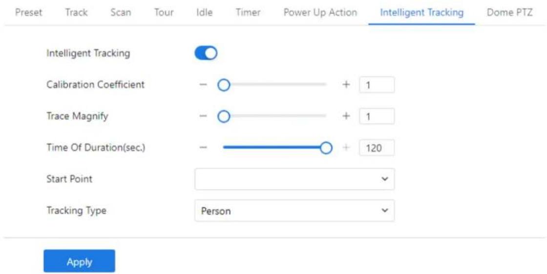
text_image
Preset Track Scan Tour Idle Timer Power Up Action Intelligent Tracking Dome PTZ Intelligent Tracking Calibration Coefficient - ○ + 1 Trace Magnify - ○ + 1 Time Of Duration(sec.) - —○ + 120 Start Point Tracking Type Person ApplyStep 2 Set all parameters for intelligent tracking. Table 10-1 describes the specific parameters.
Table 10-1 Parameters of intelligent tracking
| Parameter | Description | Setting |
| Intelligent Tracking | Click the button on to enable the intelligent tracking | [How to set]Click the button on.[Default value]OFF |
| Calibration Coefficient | It is equivalent to a control coefficient, and real-time tracking doubling rate nonlinear positive correlation; Usually the higher the installation height, the greater the calibration coefficient value; it ranges from 1 to 30. | [Setting method]Drag the slider.[Default value]1 |
| Trace Magnify | It is the value of lens zoom, which has a large influence on the real-time tracking magnification; it ranges from 0 to 30. | [Setting method]Drag the slider.[Default value]7 |
| Time of Duration (sec.) | The maximum time of a tracking period ranges from 0 to 300 s. | [Setting method]Drag the slider.[Default value]120 |
| Start Point | Start point of the tracking, you can choose the preset or none. The preset should be set in advanced. | [Setting method]Choose from drop-down list.[Default value]None |
D-Link F-Series Camera User Guide
PTZ
| Tracking Type | Choose the tracking type, person or car. | [Setting method] Choose from drop-down list. [Default value] Person |
Step 3 Click Apply. The message "Apply success!" is displayed, and the system will save the settings.
10.4.11 Dome PTZ
Description
The high speed dome cameras are connected to 485 keyboards, users can use the keyboard to control the cameras' PTZ menu.
Procedure
Step 1 Navigate to Setting > PTZ > Dome PTZ.
The Dome PTZ page is displayed, as shown in Figure 10-12.
Figure 10-12 Dome PTZ page
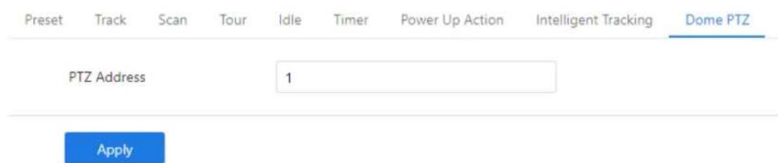
text_image
Preset Track Scan Tour Idle Timer Power Up Action Intelligent Tracking Dome PTZ PTZ Address 1 ApplyStep 2 Input the PTZ address, the default is 1.
Step 3 Click Apply.
The message "Apply success!" is displayed, and the system will save the settings.
10.5 Configure PTZ Keyboard
Description
When the IP camera is connected to an external PTZ by RS485 port, you can set external PTZ parameters, such as PTZ Protocol, PTZ Address, Baud Rate, and Data Bits.

CAUTION
This function is available only for a camera connected to an external PTZ. The PTZ address must be set to the address of the external PTZ; otherwise, the external PTZ cannot be used.
D-Link F-Series Camera User Guide
PTZ
Procedure
Step 1 Navigate to Setting > System > Settings > PTZ Keyboard.
The PTZ page is displayed, as shown in Figure 10-13.
Figure 10-13 PTZ page
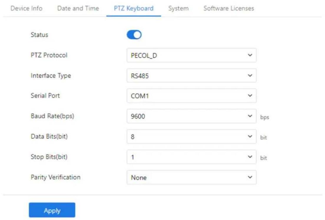
text_image
Device Info Date and Time PTZ Keyboard System Software Licenses Status PTZ Protocol PECOL_D Interface Type RS485 Serial Port COM1 Baud Rate(bps) 9600 bps Data Bits(bit) 8 bit Stop Bits(bit) 1 bit Parity Verification None ApplyStep 2 Set the parameters according to Table 10-2.
Table 10-2 Parameters of PTZ Keyboard
| Parameter | Description | Setting |
| PTZ | Enable this function if the device connects to an external PTZ.NOTEThis check box is dimmed for an IP dome camera. | [Setting method]Click the button on to enable PTZ configuration. |
| PTZ Protocol | Protocol used by the external PTZ, such as PELCO_D and PELCO_P. | [Setting method]Select a value from the drop-down list box. |
| PTZ Address | Address of the external PTZ. | |
| Serial Port | The default value is COM1. | NOTEWhen external PTZ parameters are configured, these parameters must match the settings on the |
| Baud Rate | Baud rate used by the external PTZ.The value ranges from 300 bit/s to 115200 bit/s. The default value is 4800 bit/s. |
D-Link F-Series Camera User Guide
PTZ
| Parameter | Description | Setting |
| Data Bits | The value must match the setting used by the external PTZ. It can be set to a value ranging from 4 to 8. Generally, the value is 8. | external PTZ. |
| Stop Bits | N/A | |
| Parity Verification | N/A |
Step 3 Click Apply. The message "Apply success!" is displayed, and the system will save the settings.
10.6 Smoke and Flame Detection
Description
The Smoke and Flame Detection feature enables the camera to monitor designated areas for signs of smoke or fire. When smoke or flame is detected within the defined detection zone, the system automatically generates an alarm to alert the user..
Procedure
Step 1 Navigate to IVS > Advanced Intelligent Analysis >> Smoke and Flame Detection to access the Smoke and Flame Detection interface, as shown in Figure 10-14.
D-Link F-Series Camera User Guide
PTZ
Figure 10-14 Smoke and flame detection page
Smoke and Flame Detection
Basic Settings
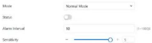
text_image
Mode Normal Mode Status Alarm Interval 10 (1-100ps) Sensitivity - + 5Event Actions
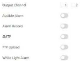
text_image
Output Channel 1 2 Audible Alarm Alarm Record SMTP FTP Upload White Light Alarm
natural_image
Simple green outline of a rectangular frame with red dots at vertices (no text or symbols)Schedule

text_image
Sun Mon Tue Wed Thu Fri Sat 0 2 4 6 8 10 12 14 16 18 20 22 24 Select All Clear AllApply
Step 2 Set all parameters for smoke and flame detection, please refer to 9.5.1 Step 3.
Step 3 Set a deployment area. Move the cursor to the drawing interface and click to generate a point, move the cursor to draw a line, and then click to generate another point. This is how a line is generated. In this way, continue to draw lines to form any shape, and right-click to finish line drawing.

NOTE
• A drawn line cannot cross another one, or the line drawing fails.
• Any shape with 32 sides at most can be drawn.
• The quantity of deployment areas is up to 8.
Step 4 Set deployment time, please refer to 7.4 Step 4.
Step 5 Click Apply. The message "Apply success!" is displayed, and the system will save the settings.

NOTE
For dual-lens, multi channels, panoramic cameras, the all IVS actions should choose one channel to set. The alarm information can linkage to other channels, users select on demand.
D-Link F-Series Camera User Guide
PTZ
Figure 10-15 Choose channel
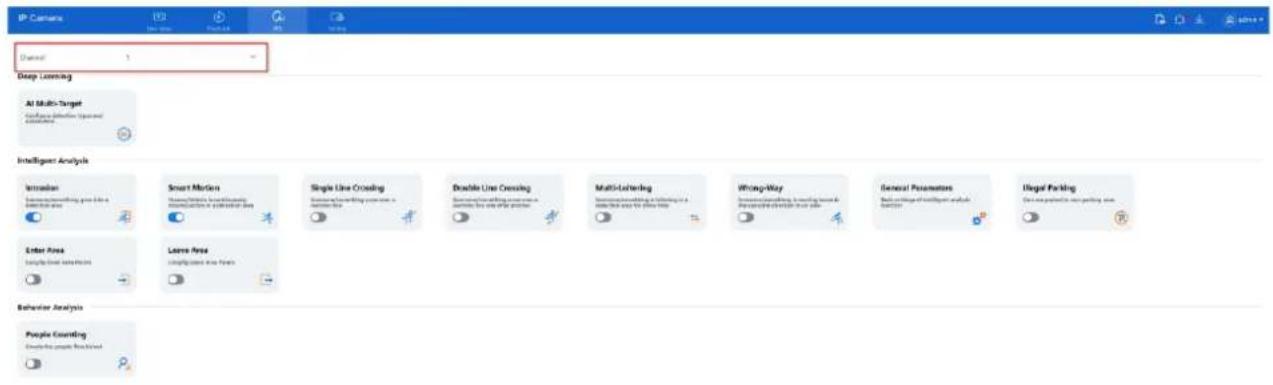
text_image
IP Camera Channel 1 Deep Learning AI Multi-Target Advance detection (optional) applicators Intelligent Analysis Intrusion Smart Morion Single Line Crossing Double Line Crossing Multi-Learning Wrong-Way General Parameters Illegal Parking Enter Area Large Area Lear Area False Area Behavior Analysis People Counting Create people from all workFigure 10-16 Linkage channels
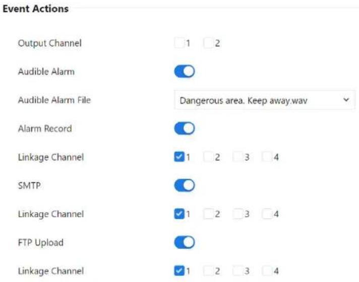
text_image
Event Actions Output Channel 1 2 Audible Alarm Audible Alarm File Dangerous area. Keep away.wav Alarm Record Linkage Channel 1 2 3 4 SMTP Linkage Channel 1 2 3 4 FTP Upload Linkage Channel 1 2 3 411 Panoramic Cameras
11.4 CVBS Function (Only for Some Models)
Preparation
Ensure a display device is connected to the camera's VIDEO OUT port.
Description
When the analog output function is enabled, the IP camera can transmit analog video signals to a video server or display device via the VIDEO OUT port. This is useful for legacy analog systems or real-time local display.
Procedure
Step 1 Navigate to Setting > Image > CVBS.
The BNC Video Output page is displayed, as shown in Figure 11-1.
Figure 11-1 BNC video output page
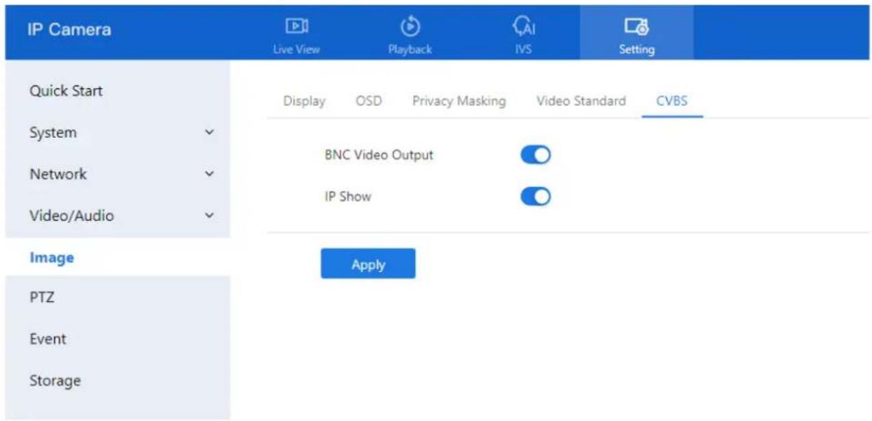
text_image
IP Camera Live View Playback IVS Setting Quick Start Display OSD Privacy Masking Video Standard CVBS System BNC Video Output Network IP Show Video/Audio Image Apply PTZ Event StorageStep 2 Toggle the switch ON to enable BNC Video Output.
Step 3 Toggle the switch ON to enable BNC Video Output.
Step 4 Toggle the switch ON to enable IP Show if you want the IP address displayed on the video output.
Step 5 Click Apply.
A message will appear: "Apply success!", indicating the settings have been saved.
Note: This function is only supported on specific camera models with analog output capabilities.
D-Link F-Series Camera User Guide
Panoramic Cameras
11.5 Fisheye Camera
Procedure
Step 1 Navigate to Setting > Image > Fisheye.
The Fisheye page is displayed, as shown in Figure 11-2.
Figure 11-2 Fisheye page

text_image
IP Camera Live View Playback IVS Setting Quick Start Display OSD Privacy Masking Video Standard Fish Eye System Video.One-Channel Network Mounting Mode Wall Video/Audio Display Mode Fish Eye Image When the Fisheye Device Switches to Non-Fisheye Mode, The Intelligent Function Cannot be Used. Event ApplyStep 2 Select the Video Mode:
○ One Channel: For 4PTZ fisheye models, displays a quad view in real-time.
o Multi-Channels: For 4PTZ fisheye models, displays a single dewarped view in real-time.
Note: Switching video modes will reboot the device automatically.
Step 3 Select the Mounting Mode based on your installation:
○ Wall
○ Ceiling
- Desktop
Step 4 Choose the Display Mode from the drop-down list:
- Fisheye: Original 360° panoramic view; this is the only mode that supports intelligent analysis.
- Double Panorama: Dual 180° panoramic views.
- 4PTZ: Quad-view dewarped image layout.
○ Single Panorama: Single 180° panoramic view. - Fisheye+3PTZ: Combined 360° view with three dewarped PTZ views.
Multi-channel fisheye types only support 4PTZ and Fisheye+3PTZ display modes.
Step 5 Click Apply.
A message will appear stating "Apply success!", confirming that the settings have been saved.
D-Link F-Series Camera User Guide
Panoramic Cameras
Note: When switching from Fisheye mode to any non-fisheye mode, intelligent functions will be disabled.
11.6 Dual-Lens
11.6.1 Dual-Lens
For cameras equipped with dual lenses, you can configure the video output mode from Setting > Image > Dual-Lens, as shown in Figure 11-3.
Figure 11-3 Dual-Lens
| IP Camera Live View Playback IVS Setting | |
| Quick Start Display OSD Privacy Masking Video Standard Dual-Lens System ✓ Video Mode Multi Channels ✓ Network ✓ | |
| Video/Audio ✓ Apply | |
| Image | |
| Event | |
| Storage | |
| IP Camera Live View Playback IVS Setting | |
| Quick Start Display OSD Privacy Masking Video Standard Dual-Lens System ✓ Video Mode Stitching Mode ✓ Network ✓ Stitching Distance 2 (2-200M) Video/Audio ✓ | |
| Image Apply | |
| Event | |
| Storage | |
Available Video Modes:
- Multi-Channels
○ Each lens operates independently.
- Two separate video streams are displayed — each corresponding to a different channel.
- Stitching Mode
○ Combines video from both lenses into one seamless panoramic view.
D-Link F-Series Camera User Guide
Panoramic Cameras
- You can set the Stitching Distance (range: 2–200 meters) to achieve smooth, natural blending based on the physical installation environment.

NOTE
Important:
Switching between video modes will reset all IVS (Intelligent Video Surveillance) settings. Make sure to back up your configuration if necessary before changing the mode.
11.7 Panoramic Camera
11.7.1 RS458
Purpose:
Configure the RS485 interface to connect the panoramic camera with an external high-speed PTZ camera.
Step 1 Go to Setting > System > Settings > RS485
The RS485 configuration interface is shown in Figure 11-4.

text_image
IP Camera Live View Playback IVS Setting Quick Start Device Info Date and Time RS485 System IR Led Config Software Licenses System Status PTZ Protocol PECOL_D PTZ Address 1 Serial Port COM1 Baud Rate(bps) 9600 bps Data Bits(bit) 8 bit Stop Bits(bit) 1 bit Parity Verification None Image Apply Event Storage| Parameter | Description | Setting |
| Status | Enable this function if the device connects to high-speed camera. NOTE This check box is dimmed for an IP dome camera. | [Setting method] Click the button on to enable PTZ configuration. |
D-Link F-Series Camera User Guide Panoramic Cameras
| Parameter | Description | Setting |
| PTZ Protocol | Protocol used by the external PTZ, such as PELCO_D and PELCO_P. | [Setting method]Select a value from the drop-down list box.NOTEWhen parameters are configured, these parameters must match the settings on high-speed camera. |
| PTZ Address | Address of the high-speed camera. | |
| Serial Port | The default value is COM1. | |
| Baud Rate | Baud rate used by the external PTZ. The value ranges from 300 bit/s to 115200 bit/s. The default value is 4800 bit/s. | |
| Data Bits | The value must match the setting used by the external PTZ. It can be set to a value ranging from 4 to 8. Generally, the value is 8. | |
| Stop Bits | N/A | |
| Parity Verification | N/A |
Step 2 Click Apply. The message "Apply success!" is displayed, the system will save the settings.
11.7.1 IR Led Config
Purpose:
Configure the infrared (IR) LEDs for panoramic cameras to ensure proper night vision functionality based on camera orientation.
Step 1 Go to Setting > System > Settings > IR Led Config. The IR LED configuration interface is shown in Figure 11-4.
Figure 11-4 IR led config
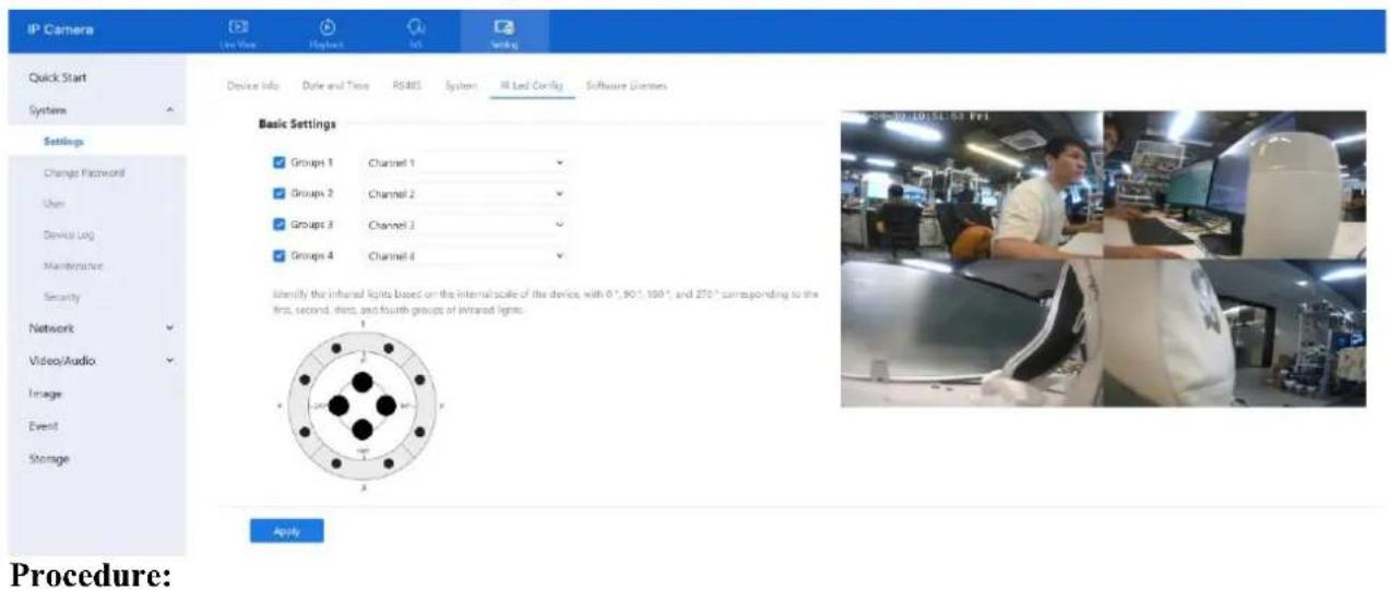
text_image
IP Camera Quick Start System Settings Change Password User Device Log Maintenance Security Network Video/Audio Image Event Storage Device Info Date and Time RS485 System MR Led Config Software Diaries Basic Settings Groups 1 Channel 1 Groups 2 Channel 2 Groups 3 Channel 3 Groups 4 Channel 4 Identify the infrared lights based on the internal scale of the device, with 0",90",150", and 270" corresponding to the first, second, third, and fourth groups of infrared lights. Apply Procedure:D-Link F-Series Camera User Guide
Panoramic Cameras
Step 2 Channel Assignment:
Each IR LED group corresponds to a direction on the internal camera dial:
○ Group 1 = 0°
○ Group 2 = 90°
○ Group 3 = 180°
○ Group 4 = 270°
Assign channels based on the installation direction, as marked on the device housing.
Step 3 Adjust as Needed:
If the camera is physically moved or rotated, update the channel assignments so the IR LEDs align with the actual field of view.
Step 4 Click Apply.
When the message "Apply success!" appears, the settings are saved.
Note: Correct LED-to-channel alignment is critical for effective illumination.
11.7.2 CVBS
Purpose: Enable analog video display through a BNC cable.
Step 1 Go to Setting > Image > CVBS. The CVBS configuration interface is shown in Figure 11-5.
Figure 11-5 CVBS
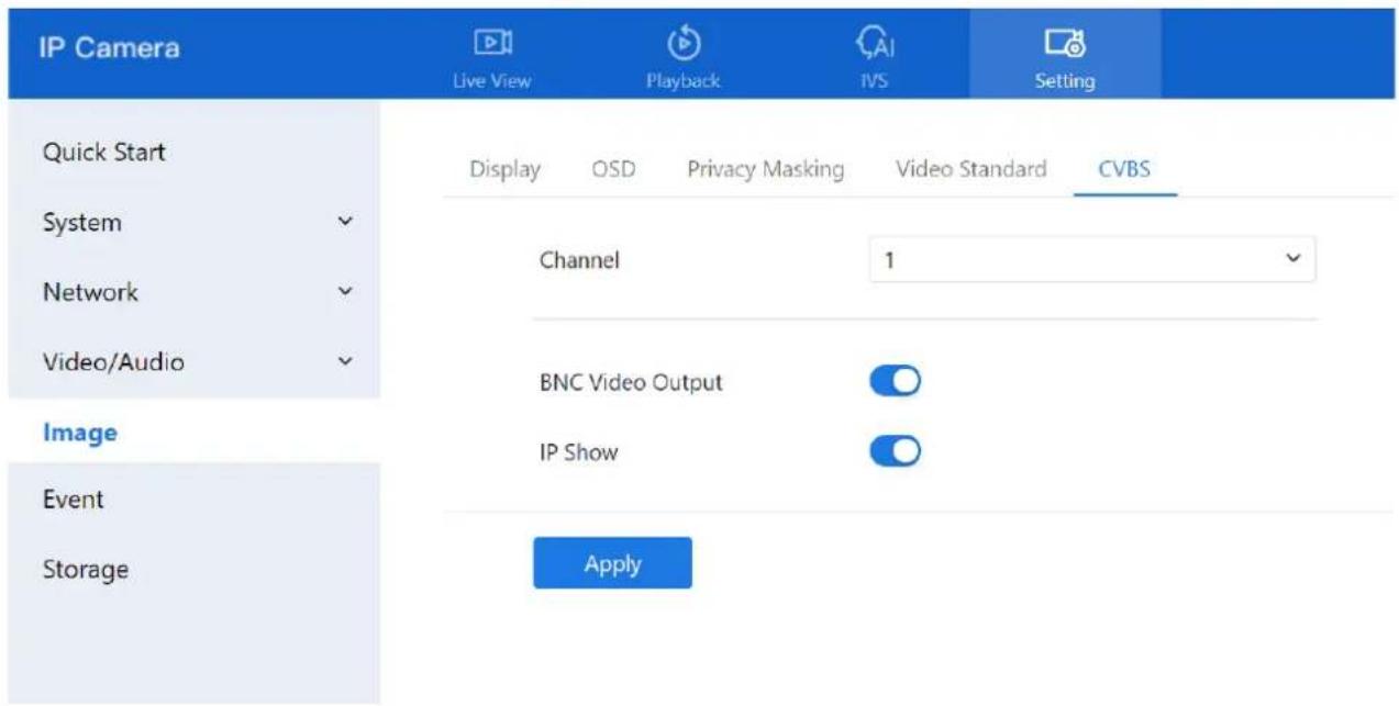
text_image
IP Camera Live View Playback IVS Setting Quick Start Display OSD Privacy Masking Video Standard CVBS System Channel 1 Network Video/Audio BNC Video Output IP Show Image Event Storage ApplyD-Link F-Series Camera User Guide Panoramic Cameras
Step 2 Enable BNC Video Output to activate analog signal output.
Step 3 Enable IP Show to display the IP address on the analog output screen.
Step 4 Use the dipswitch on the device to switch video channels if needed.
11.8 For Special Cameras
11.8.1 General Parameters
Description
Target filtering helps reduce false alarms by ignoring brief or unstable appearances of people or vehicles in the detection area. Only stable, continuous targets will trigger intelligent analysis alarms.
Procedure
Step 1 Go to IVS > Intelligent Analysis > General Parameters to access the advanced setting interface, as shown in Figure 11-6.
Figure 11-6 General Parameters page
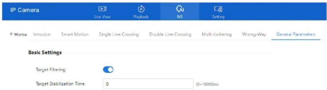
text_image
IP Camera Live View Playback NS Setting ← Home Intrusion Smart Motion Single Line Crossing Double Line Crossing Multi-Loitering Wrong-Way General Parameters Basic Settings Target Filtering Target Stabilization Time 0 (0~10000)msApply
Step 2 Enable Target Filtering
- Toggle the switch to activate the feature.
D-Link F-Series Camera User Guide Panoramic Cameras
Step 3 Set Target Stabilization Time
- This is the minimum duration a person or vehicle must remain in the detection area before an alarm is triggered.
- Input the desired stabilization time in seconds.
Step 4 Click Apply
- When the message "Apply success!" appears, the settings are successfully saved.
Note: This function is useful in environments with frequent brief movements, helping the system focus only on sustained activity.
11.8.2 Illegal Parking (Only for Some Models)
Description
This function generates an alarm when a vehicle remains in a designated detection area longer than the allowed parking time.
Procedure
Step 1 Navigate to IVS > Intelligent Analysis > Illegal Parking, as shown in Figure 11-7.
Figure 11-7 Illegal parking settings page
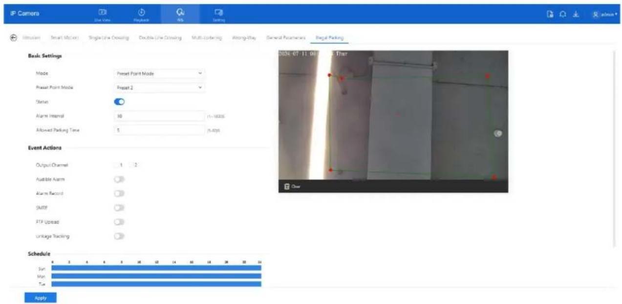
text_image
IP Camera Line View Playback ABS Setting Simulation Smart Motion Single Line Ordering Double Line Ordering Multi-Ordering Among-Step General Parameters Legal Parking Basic Settings Mode Preset Point Mode Preset Point Mode Preset 2 Status Alarm Interval 10 (1-16000) Allowed Parking Time 5 (5-4000) Event Actions Output Channel 1 2 Audible Alarm Alarm Record SMTP FTP Upload Unluge Tracking Schedule Sun Mon Tue ApplyStep 2 Configure the following parameters:
(Refer to Section 9.2.1 Step 2 for details on parameter settings such as sensitivity, interval, and output actions.)
Step 3 Set a Deployment Area:
- Use the mouse to draw a region on the live video feed.
Step 4 Set the Schedule Time:
• See Section 7.1 Step 4 for instructions on setting active monitoring times.
D-Link F-Series Camera User Guide Panoramic Cameras
Step 5 Click Apply
- A confirmation message "Apply success!" will confirm that the settings have been saved.
11.8.3 Enter Area
Description: Triggers an alarm when a target (such as a person or vehicle) enters a designated area during a scheduled time.
Step 1 Navigate to Configuration > Intelligent Analysis > Enter Area, as shown in Figure 11-8.
Figure 11-8 Enter Area

text_image
IP Camera Live View Playlock MS Setting Interaction Smart Motion Single Line Crossing Double Line Crossing Multi-Loitering Wrong-Way General Parameters Illegal Parking Enter Area Leave Area Channel 4 Basic Settings Status Alarm Interval 10 (1~1800s) Sensitivity - 5 Limit Type Area Listings Area ID Min Max Status 1 42 × 50 85 × 50 Event Actions Output Channel 1 2 Audible Alarm Audible Alarm File Dangerous area. Keep away way Alarm Record Linkage Channel 1 2 3 4 SMTP FTP Upload Schedule Sun Mon ApplySet all parameters for enter area, please refer to chapter Figure 3-6
11.8.4 Leave Area
Description: Triggers an alarm when a target exits a predefined area during a valid monitoring period.
Step 1 Navigate to Configuration > Intelligent Analysis > Leave Area, as shown in Figure 11-9.
D-Link F-Series Camera User Guide Panoramic Cameras
Figure 11-9 Leave Area
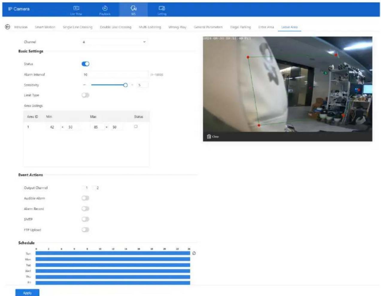
text_image
IP Camera List View Playback IVS Setting Intrusion Smart Motion Single Line Crossing Double Line Crossing Multi-Loitering Wrong-Way General Parameters Illegal Parking Enter Area Leave Area Channel 4 Basic Settings Status Alarm Interval 10 (1~10025) Sensitivity - 5 Limit Type Area Listings Area ID Min Max Status 1 42 × 50 85 × 50 Event Actions Output Channel 1 2 Audible Alarm Alarm Record SMTP FTP Uploaded Schedule Sun Mon Tue Wed Thu Fri ApplySet all parameters for leave area, please refer to chapter Figure 3-6
11.8.5 Heat Map
11.8.5.1 Heat Map Set (Only for Some Models)
The heat map is a visual data analysis tool that highlights areas of interest—such as customer movement patterns, target locations, and activity zones—using color-coded overlays. Once enabled, the camera automatically monitors and counts foot traffic within the detection area. It then visualizes the frequency of activity through varying color intensities, making it easy to identify high and low traffic regions.

NOTE
The setting and export of heat map is only applied for some models.
Step 1 Navigate to IVS > Behavior Analysis > Heat map > Set interface, as shown in Figure 11-10.
D-Link F-Series Camera User Guide Panoramic Cameras
Figure 11-10 Heat map set page
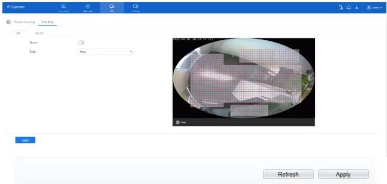
text_image
IP Camera Live Star Playback IVS Setting People Counting Year Map Set Sort Status Type Hour 2014-06-03 10:28:17:55 Apply Refresh ApplyStep 2 Enable Heat Map Function:
- Toggle the Status button to turn on the heat map function.
- Note: This feature is disabled by default and must be manually activated.
Step 3 Select Type:
○ Choose the statistical granularity:
- Hour: Collects and displays 24 data segments per day.
- Day: Displays one aggregated data point per day.
○ Switching between types will clear previously collected data. Please proceed with caution.
Step 4 Click "Apply":
Once the settings are configured, click Apply to save.
- The system will confirm with the message: "Apply success!"
11.8.5.2 Heat Map Report
Step 1 Navigate to IVS > Behavior Analysis > Heat Map > Report, the page as shown in Figure 11-12.
D-Link F-Series Camera User Guide Panoramic Cameras
Figure 11-12 Heat map report page

text_image
IP Camera Live User Readout MS Setting People Counting Heat Map Set Report Statistical Type Hour Time 2024-08-02 10:00:00 Download Search 2024-08-02 10:00:00 Low HighTable 11-1 Parameters of heat map
| Parameter | Description | Setting |
| Type | Select either Data or Picture. Data is shown in numerical format and can be downloaded. Pictures display different heat levels via color mapping. | [How to set]Choose from the drop-down list[Default value]Normal mode |
| Statistics type | Select the time unit for analysis: Year, Month, Day, or Hour. | [How to set]Click the button on.[Default value]OFF |
| Time | Specify the time range for searching or downloading heat map data. | [How to set]Choose from the drop-down list |
| Heat map bar | Displays color-coded heat levels. Each color represents a different level of activity. The maximum value reflects the peak data in any area during the selected time. | Null |
Step 2 Set Set the time range for analysis.
Step 3 Click Search to view the heat map directly, or
Step 4 Click Download to export the data in CSV format to your local folder.
Table 11-2 describes the common faults and solutions.
Table 11-2 Common faults and solutions
| Common Fault | Possible Cause | Solution |
| When you enter the device IP address in the address box of Internet Explorer and press Enter, the message "There is a problem with this website's security certificate." is displayed. | The certificate is not installed. | Click Continue to this website (not recommended) to proceed. |
| The web management system cannot be accessed. | The network is disconnected. | Connect the PC directly to the camera, and verify that the web management system can be accessed.Run the ping command to verify that the camera is reachable. |
| The IP address is used by another device. | Connect the PC directly to the camera and configure the IP address of the camera. | |
| The IP addresses of the PC and IP camera are on different networks. | Check the IP address, subnet mask, and gateway settings on the IP camera, and change the settings as required. | |
| The PTZ or dome cannot be controlled. | The protocol, baud rate, or address is incorrect. | Change the protocol, baud rate, and address in the web management system to those used by the PTZ or dome. |
| The signal cable is not properly connected. | Check the signal strength and connect the signal cable properly. |
D-Link F-Series Camera User Guide
Troubleshooting
| Common Fault | Possible Cause | Solution |
| After the IP camera is upgraded, the web management system cannot be accessed. | The browser cache is not deleted. | To delete the browser cache, proceed as follows:1. Open browser.2. Press Ctrl + Shift +Delete.The Delete Browsing History dialog box is displayed.3. Select all check boxes.4. Click Delete.Login to the web management system again. |
| The IP camera cannot be upgraded. | The network is disconnected.The network settings are incorrect. | Confirm that the upgrade network is connected.Check the network settings. |
| The upgrade package is incorrect. | Obtain the correct upgrade package and upgrade the IP camera again. | |
| The accuracy of people counting is bad. | The installation method is fault. | Install camera and draw the line following as figure.Gerneral Environment is over 480Lux, 5000K[Lens (mm) Pixel: distance of recognition2.8 5M:3~408M:3~452.7~13.5 zoom=1 5M:3~358M:3~452.7~13.5 zoom=5 5M:5~1058M:4.5~30 |
| The capture performance of AI Multi-target is bad. | The lens is too short. | It is recommended to use 6mm focus length lens or above. |
Acronyms and Abbreviations
| A | |
| ADSL | Asymmetric Digital Subscriber Line |
| C | |
| CBR | Constant Bit Rate |
| CGI | Common Gateway Interface |
| CMS | Central Management System |
| D | |
| DHCP | Dynamic Host Configuration Protocol |
| DNS | Domain Name Server |
| DDNS | Dynamic Domain Name Server |
| E | |
| EAP | Extensible Authentication Protocol |
| F | |
| FTP | File Transfer Protocol |
| G | |
| GAMA | Graphics Assisted Management Application |
| H | |
| HTTP | Hyper Text Transfer Protocol |
| HTTPS | Hypertext Transfer Protocol Secure |
| I | |
| ID | Identity |
| ISO | International Standard Organization |
| IP | Internet Protocol |
| IPC | Internet Protocol Camera |
| IVS | Intelligent Video System |
| L | |
| LPS | Limited Power Source |
| M | |
| MJPEG | Motion Joint Photographic Experts Group |
| D-Link F-Series Camera User GuideAcronyms and Abbreviations | |
| MAC | Media Access Control |
| MTU | Media Transmission Unit |
| N | |
| NAS | Network Attached Storage |
| NTP | Network Time Protocol |
| NTSC | National Television Standards Committee |
| O | |
| OSD | On Screen Display |
| P | |
| PAL | Phase Alteration Line |
| PoE | Power over Ethernet |
| PPPoE | Point-to-Point Protocol over Ethernet |
| PTZ | Pan/Tilt/Zoom |
| R | |
| ROI | Region of Interest |
| RSTP | Rapid Spanning Tree Protocol |
| S | |
| SMTP | Simple Mail Transfer Protocol |
| SSL | Secure Sockets Layer |
| V | |
| VBR | Variable Bit Rate |