DCS-F4605EK - Security Camera D-LINK - Free user manual and instructions
Find the device manual for free DCS-F4605EK D-LINK in PDF.

User questions about DCS-F4605EK D-LINK
0 question about this device. Answer the ones you know or ask your own.
Ask a new question about this device
Download the instructions for your Security Camera in PDF format for free! Find your manual DCS-F4605EK - D-LINK and take your electronic device back in hand. On this page are published all the documents necessary for the use of your device. DCS-F4605EK by D-LINK.
USER MANUAL DCS-F4605EK D-LINK
This document describes how to use the web management system, including network access, network configuration, and troubleshooting.
Intended Audience
This document is intended for:
Technical support engineers
Maintenance engineers
IP camera operators
Symbol Conventions
The symbols that may be found in this document are defined as follows.
| Symbol | Description | |
 | DANGER | Indicates an imminently hazardous situation which, if not avoided, will result in death or serious injury. |
 | WARNING | Indicates a potentially hazardous situation which, if not avoided, could result in death or serious injury. |
 | CAUTION | Indicates a potentially hazardous situation which, if not avoided, may result in minor or moderate injury. |
 | NOTICE | Indicates a potentially hazardous situation which, if not avoided, could result in equipment damage, data loss, performance deterioration, or unanticipated results.NOTICE is used to address practices not related to personal injury. |
 | NOTE | Calls attention to important information, best practices and tips.NOTE is used to address information not related to personal injury, equipment damage, and environmental deterioration. |
Special Announcement
This manual may contain misprints, technology information that is not accurate enough, and description of product function and operation that is slightly inconsistent with the actual product. The manufacturer will update this manual according to product function enhancement or changes and regularly update the software and hardware described in this manual. Updated information will be added to new versions of this manual without prior notice.
This manual is only for reference. There may be slight difference among different models. Please refer to the actual products.
Update Version
| Version | Update Time | Description |
| V1.0 | 02/2023 | Support Local Server and no plugin to play live video. |
Contents
About This Document ....
Contents ..... iii
1 Quick Start 1
1.1 Login and Logout .... 1
1.2 Change the Password 2
1.3 Browse Real-Time Videos 3
1.4 Main Page Layout 6
1.5 Playback 9
1.6 People Counting (Only for Some Models) ..... 10
2 Parameters of PTZ 12
2.1 Control and Configure the PTZ (Only for Some Models) 12
2.2 Configure and Invoke Preset Positions 14
2.3 Configure and Invoke Tracks 14
2.4 Configure and Invoke Scans 15
2.5 Configure and Invoke Tours 16
2.6 Configure Idles ..... 17
2.7 Configure Timer 17
2.8 Configure Extension 18
3 Image Settings 20
3.1.1 Access the Image Settings Interface ..... 20
3.1.2 Mode 20
3.1.3 Image Setting 21
3.1.4 Scene Mode 23
3.1.5 Exposure 24
3.1.6 WB Setting 27
3.1.7 DayNight 28
3.1.8 Noise Reduction 31
3.1.9 Enhance Image 33
3.1.10 Zoom Focus (Only for Some Models) 35
4 Configure the Device.... 39
4.1 Device Information 39
4.2 Video and Audio Stream 41
4.3 ROI Parameter 45
4.4 Snapshot 47
4.5 Local Network 48
4.6 Device Port 51
4.7 Date and Time 52
4.8 Camera 55
4.9 OSD 56
4.10 Audio Input (Only for Some Models) 60
4.11 Audio Output (Only for Some Models)....61
4.12 Dome PTZ (Only for Some Models) ..... 62
4.13 CVBS Function (Only for Some Models) .....63
4.14 System Service 63
4.15 Voice Denoise (Only for Some Models) 64
4.16 Software Licenses 65
5 Configure External Devices 66
5.1 External PTZ Parameters (Only for Some Models) 66
6 Advanced Intelligent Analysis 68
6.1 Smoke and Flame Detection 68
7 Configure Intelligent Analysis 72
7.1 Intrusion 72
7.2 Single Line Crossing 76
7.3 Double Line Crossing 79
7.4 Multi-Loitering 82
7.5 Retrograde 85
7.6 Illegal Parking (Only for Some Models) . 88
7.7 People Counting (Only for Some Models) ..... 91
7.8 Smart Motion 95
8 Configure Intelligent Tracking (Only for Some Models) 100
8.1 Intelligent Tracking 100
9 Configure the Alarm Function 102
9.1 Alarm Output (Only for Some Models) 102
9.2 Disk Alarm 103
9.3 Network Alarm 104
9.4 Day Night Switch Alarm 105
9.5 I/O Alarm Linkage (Only for Some Models) 106
9.6 Motion Alarm Linkage 108
9.7 Push Message 110
9.8 Audible Alarm Output (Only for Some Models) ..... 111
9.9 Abnormal Sound Detection (Only for Some Models) 112
9.10 Flashlight Alarm Output (Only for Some Models) 113
9.11 Whitelight Alarm Output (Only for Some Models) 114
10 AI Multiobject 116
10.1 AI Configuration 116
11 Configure the Recording Function 119
11.1 Record Policy 119
11.2 Record Directory.... 120
11.2.1 Configure the SD Card 122
11.2.2 Configure the FTP 123
11.2.3 Configure the NAS 125
12 Configure the Privacy Mask Function 127
13 Configure the Network Service 129
13.1 802.1x 129
13.2 DDNS 129
13.3 PPPoE 131
13.4 Port Mapping 132
13.5 SMTP 134
13.6 FTP 135
13.7 IP Filter 137
13.8 CGI Alarm Service Center 139
13.9 SNMP 142
13.10 QOS 145
13.11 Platform Access 146
14 Privilege Manager 148
14.1 Configure a User 148
15 Configure Protocol Parameters 151
15.1 Protocol Information 151
15.2 Security Authentication 151
15.3 Onvif Configuration 152
15.4 Multicast Parameters ...... 154
16 Query Device Logs 156
16.1 Query Operation Logs 156
16.2 Query Alarm Logs 157
16.3 Collect All Logs 158
17 Maintain the Device 159
17.1 Restart a Device 159
17.2 Auto Restart 160
17.3 Upgrade the Software Package 160
17.4 Restore Device to Factory Settings 161
17.5 Export / Import Configuration 161
18 Local Configuration 163
19 Troubleshooting 164
A Acronyms and Abbreviations 165
1 Quick Start
1.1 Login and Logout

CAUTION
To access the web interface through Microsoft Edge, Chrome or Firefox browser; Otherwise some functions may be unavailable.
Login
Step 1 Open Microsoft Edge, enter the IP address of the IP camera (default value: 192.168.0.120) in the address box, and click on the Enter button.
The login page is displayed, as shown in Figure 1-1.
Figure 1-1 Login Page

text_image
IP CAMERA English ▼ User Name admin Password ••••••• LoginStep 2
Enter the user name and password.
The default name and password are both admin. Modify the password when you login the system for first time to ensure system security.
After modifying password, you need to wait at least three minutes then power off to make sure modifying successfully. Or login the Web again to test the new password.
You can change the system display language on the login page.
Step 3 Click Login to enter the interface.
The main page is displayed.
---End
Logout
Click

in the upper right to return to login page.
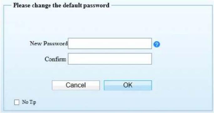
1.2 Change the Password
Description
For the first login, the change default password page is as shown in Figure 1-2.
Figure 1-2 Change the Default Password Page
text_image
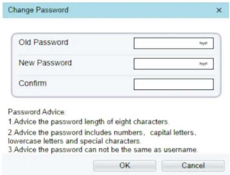
Please change the default password New Password Confirm Cancel OK No TipOr click to change the password to login the system, as show in Figure 1-3.
Figure 1-3 Change Password Dialog Box
text_image
Change Password Old Password New Password Confirm Password Advice: 1. Advice the password length of eight characters. 2. Advice the password includes numbers, capital letters, lowercase letters and special characters. 3. Advice the password can not be the same as username. OK CancelProcedure
Step 1 Input the old password, new password, and confirmation password.
Step 2 Click OK.
If the message "Change own password success" pops up, the password is successfully changed. If the password fails to be changed, the password advice is displayed. (For example, the new password length couldn't be less than eight.).
It is advised to restarted the device three minutes later after modifying password.
Step 3 Click OK.
The login page is displayed.
1.3 Browse Real-Time Videos
Download IPC Local Server
If you want to play H.265 encoded video, you should download the latest IPC Local Server, as shown in Figure 1-4, when you login to the web management system for the first time.
Figure 1-4 Download the Plugin Page

text_image
IP CAMERA Live Video Playback People Counting Configuration Please download the latest pluginStep 1 Click “Please download the latest plugin”, download the IPCLocal Server plugin.
Step 2 Open the download file to complete installation.
Step 3 Click "Run", select destination location as shown in Figure 1-5.
Figure 1-5 Select Destination Location

text_image
Setup - IPCLocalServer Select Destination Location Where should IPCLocalServer be installed? Setup will install IPCLocalServer into the following folder. To continue, click Next. If you would like to select a different folder, click Browse. C:\Program Files (x86)\IPCLocalServer Browse... At least 7.1 MB of free disk space is required. Next > CancelStep 4 Click "Next", ready to install the plugin, as shown in Figure 1-6.
Figure 1-6 Select additional tasks
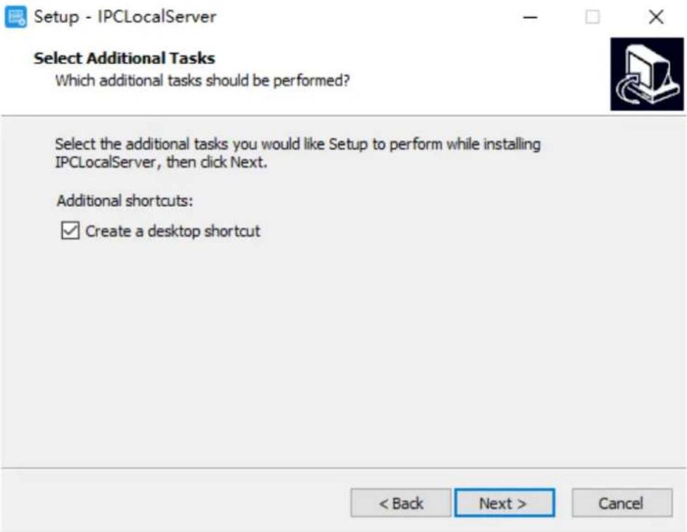
text_image
Setup - IPCLocalServer Select Additional Tasks Which additional tasks should be performed? Select the additional tasks you would like Setup to perform while installing IPCLocalServer, then click Next. Additional shortcuts: ✓ Create a desktop shortcut < Back Next > CancelStep 5 Tick "Create a desktop shortcut", Click "Next" to install the plugin, as shown in Figure 1-7.
Figure 1-7 Installing

text_image
Setup - IPCLocalServer Ready to Install Setup is now ready to begin installing IPCLocalServer on your computer. Click Install to continue with the installation, or click Back if you want to review or change any settings. Destination location: C:\Program Files (x86)\IPCLocalServer Additional tasks: Additional shortcuts: Create a desktop shortcut < Back Install CancelStep 6 Click "Finish", complete plugin installation, as shown in Figure 1-8.
Figure 1-8 Complete to Install the Plugin
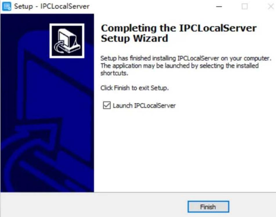
text_image
Setup - IPCLocalServer Completing the IPCLocalServer Setup Wizard Setup has finished installing IPCLocalServer on your computer. The application may be launched by selecting the installed shortcuts. Click Finish to exit Setup. ✓ Launch IPCLocalServer FinishStep 7
Reopen the browser after installing.

NOTE
If the repair tips displayed when installing the control, please ignore the prompt, and continue the installation. During the plugin installing, the browser should be closed.
---End
Description
To browse real-time videos, click Live Video. The Live Video page is displayed, as shown in Figure 1-9.
Figure 1-9 Live Video Page
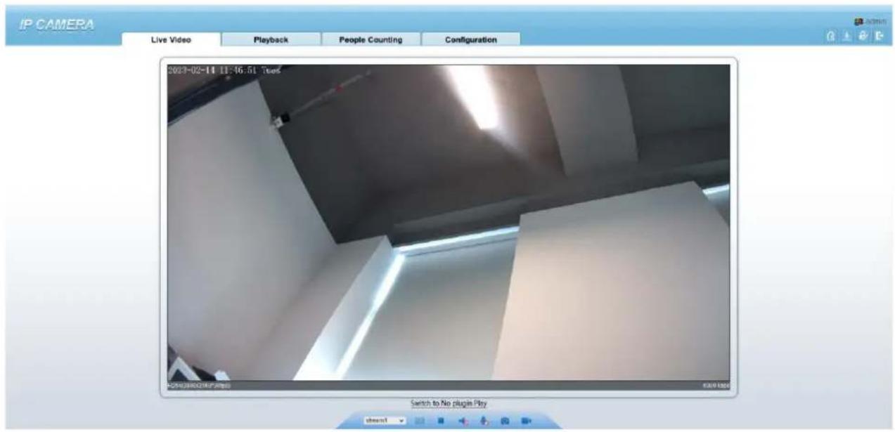
text_image
IP CAMERA Live Video Playback People Counting Configuration 2023-02-14 11:16:51 Tues F:\29\28\29\2P.S\29\pp Switch to No plugins PlayOn the Live Video page, you can perform the following operations:
Click to stop playing a video.
Click to play a video.
Double-click in the video area to enter the full-screen mode, and double-click again to exit.
Configure the PTZ. For details, see Configure the PTZ.
Control the PTZ. For details, see Controlling the PTZ.
Switch between three modes. For more details about how to configure streams, see 4.2 Video and Audio Stream.
Click to snapshot and save the photos.
Click to enable the local record.

NOTE
AI interface is supplied for some models.
1.4 Main Page Layout
On the main page, you can view real-time videos, receive alarm and fault notifications, set parameters, change the password, and log out of the system. Figure 1-10 shows the main page layout. Table 1-1 describes the elements on the main page.
Figure 1-10 Main page layout

text_image
IP CAMERA Live Video Playback People Counting Configuration 2023-02-08 16:10:04 Wed Switch to No plugin Play File:#1 Action 5 + - 4 Zoom - - - - - - - - - - - - - - - - - - - - - - - - - - - - - - - - - - - - - - - - - - - - - - - - - - - - - - - - - - - - - - - - - - - - - - - - - - - - - - - - - - - - - - - - - - - - - - - - - - - - -Table 1-1 Elements on the main page
| No. | Element | Description |
| 1 | Real-time Video Area | Real-time videos are played in this page. |
| 2 | Playback | You can query the playback videos in this area.NOTEOnly when the SD card or NAS has videos can you query the playback videos. |
| 3 | People Counting | Set the query condition to query the personnel count, the statistical can be shown in different types, such as line chart, histogram, list, for more detail information please refer to chapter 1.6 . Only for Some Models. |
| 4 | Device configuration | You can choose a menu to set device parameters, including the device information, audio and video streams, alarm setting, privacy mask function and so on. |
| 5 |  | When the device accepts an alarm signal, the alarm icon will display within 10s in the web management system. The alarm icon is displayed. You canclick  ew the alarm information. ew the alarm information. |
 | Help of intercomAbout the intercom function:×Description: Configure only Chrome browser in the HTTP environment, compatible with all browsers in HTTPS environmentsHTTP Environment Chrome Opens the intercom step:Chrome Enter 'chrome//flags*unsafely-treat-insecure-origin-as-secure' in the address barSet 'INSECURE Origins Treated as Secure' to 'Enabled'Fill in the device domain name in the input box, multiple devices named',' separation; example 'http://192.168.0.123, http://192.168.0.123:8045'Download the latest plugin IPC Local Server. | |
 | Change password, you can click to change the password. | |
 | Sign Out, you can click to return to the login page. | |
| 6 | PTZ | Only used for dome cameras, set PTZ parameters. Such as zoom in/zoom out, iris +/iris-, focus in / focus out, Preset / Track / Scan / Tour / Idle / Timer / Extension. |
| 7 | Switch to No Plugin Play | Support two methods to play live video, plugin play and no plugin play. For no plugin play, the default stream is stream 1. |
| 8 | Stream | Choose stream mode from drop-list. Set the parameters in "Configuration >Streams >Basic Streams". |
| 3D | The 3D positioning function quickly rotates the PTZ and changes the focal length in specific scenarios. You can also change the focus by drawing rectangle frames. Only for Some Models. | |
| Pause /Play video | Pause the live video or play the video. | |
| Audio | Open/close the audio. | |
| Microphone | Open/close the microphone. | |
| Snapshot | Click the icon to snapshot the video and save the images to the specified location. | |
| Local Record | Record the video and save the file to the specified location. | |
| AI Interface | Click the icon to switch to AI live video, you can view the snapshots of AI multi object, there are face, plate, car, human body, riding. Only for Some Models. | |
| Mode | Only used for fisheye camera, click the icon to choose mode to play video. |
Figure 1-11 AI multi object interface

text_image
IP CAMERA Live Video Playback Personnel Count Configuration ADD OR 13 IP Camera B→A:504 A→B:465 B→A:107 E-mail of the state STVENI CHAMP Face PlateThe face frame will show the snapshot of human face.
The plate frame will show the snapshot of license plate.
1.5 Playback
Click "Playback" at web interface, if users install SD card, and there are video in SD card, click "Playback" and the playback video will show as in Figure 1-12.
Figure 1-12 Playback interface

text_image
IP CAMERA Live Video Playback People Counting Configuration 2023/02/09 17:41:56 Time 2023/02/09 17:41:56 1h ○6h ○12h ○24h 00 00 00 00 00 00 00 All Start Time: 00:00:00 16:30:04 End Time: 2023/02/10 28:30:04 Seecl: Play, click "speaker" to switch sound on or off.
: Pause.
: Stop.
← → : Frame back / Frame play.
116x 18x 14x 12x 2x 4x 8x : Fast forward, user can choose the different speed to play.
: Snapshot, click the icon to snapshot current interface
: Backup, click the icon to start backup, drag the bar to download recording quickly, click the icon again to end up. The pop-up window of tip as shown in Figure 1-13, click the save to save the video. Click Cancel to abandon.
Figure 1-13 Record backup tip
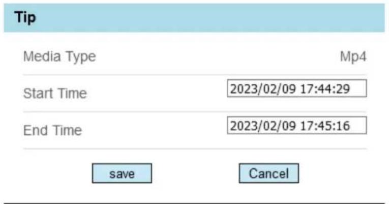
text_image
Tip Media Type Mp4 Start Time 2023/02/09 17:44:29 End Time 2023/02/09 17:45:16 save Cancel
text_image
All Alarm Record I/O Alarm Motion Alarm Day Night Switch Alarm Audio Abnormal Alarm Intrusion Smart Motion Single Line Crossing Double Line Crossing Multi-Loitering Retrograde Personnel Count Threshold Alarm Network Alarm All Start TimChoose the type of alarm, set the start time and end time to
search alarm record quickly.
1.6 People Counting (Only for Some Models)
At people counting interface, you can view the personnel count throughout setting query condition (choose the detail time at date's pop-up window).
There are three modes to show the data, such as line chart, histogram, and list, as shown in Figure 1-14
Figure 1-14 People counting interface
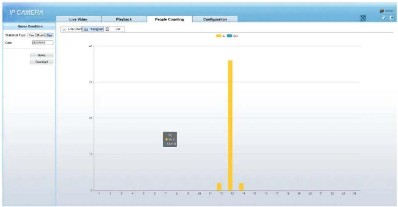
bar
| Category | Value | |---|---| | In | 12 | | Out | 0 |Click "Download" to download the query result.
Choose the mode of showing result, such as line chart, histogram and list.
Click "Query" to query the data of people counting.
The data result can be saved to local folder.
---End
2 Parameters of PTZ
2.1 Control and Configure the PTZ (Only for Some Models)
Description
All PTZ functions are only available for High Speed Network Dome and device connected to an external PTZ. The focus and zoom action can be used for motorized cameras
Controlling the PTZ
When browsing real-time videos shot by a dome camera or a camera connected to an external PTZ, you can control the PTZ to view videos shot in different directions.
Click PTZ below the Live Video page to open the PTZ Control page as shown in Figure 2-1, you can click the eight arrow keys to move the PTZ in eight directions. You can also zoom the lens and adjust the focal length.
Figure 2-1 PTZ Control area

text_image
PTZ Zoom Iris Focus North Auto FocusIn the PTZ control area, you can perform the following operations:
Slide the slider left or right beyond the PTZ rotation keys, you can adjust the PTZ rotation speed.
Click the arrows on the 📄 to move the PTZ in eight directions.
Click [ ] or to adjust the focal length.
Click or to adjust the aperture.
Click □ or □ to focus.
Click to set due north direction. You can define any direction as due north as the reference point of the PTZ rotation.
Click to enable automatic focus.
Configure the PTZ
It is available for the cameras with PTZ or connected to PTZ. PTZ Configure interface is as shown in Figure 2-2.
Figure 2-2 PTZ Configure area
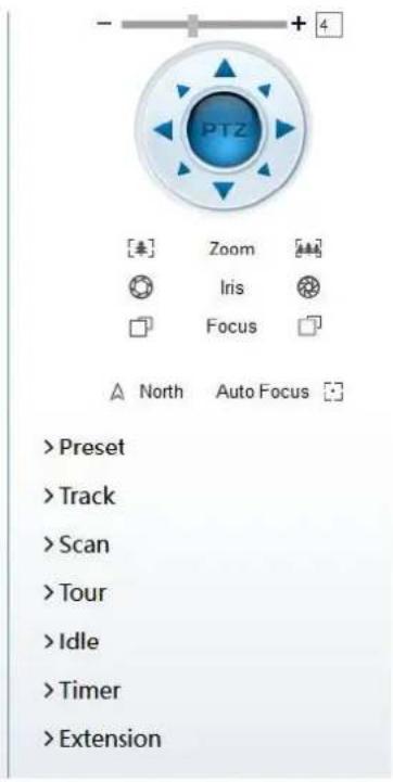
text_image
PTZ Zoom Iris Focus North Auto Focus >Preset >Track >Scan >Tour >Idle >Timer >ExtensionIn the PTZ configure area, you can perform the following operations:
Add, delete, and invoke preset positions.
Add, delete, and invoke tracks.
Add, delete, and invoke scans.
Add, delete, and invoke tours.
Set the idle.
Set the timer.
Set the extension.
Set Light On/Off and Brush function.
Brush is used to clean the lens. Light On/Off is used to control the infrared camera shields on and off.

NOTE
Brush is available only for a camera with a brush or a camera shield.
Light On/Off is available only for specific camera shields.
3D Positioning
Click 3D below the Live Video page to configure the 3D positioning function.
The 3D positioning function quickly rotates the PTZ and changes the focal length in specific scenarios. You can also change the focus by drawing rectangle frames.

NOTE
The default value of 3D Positioning is ON.
2.2 Configure and Invoke Preset Positions
You can configure preset positions and quickly rotate the camera to a preset position by invoking the preset position.
The procedure is as follows:
Step 1 Configure a preset position.
- Choose the preset ID.
- Adjust the direction of PTZ to finish the preset position setting.
- Click to save, click to rename.
Step 2 Invoke a preset position.
Select a preset position from the Preset list to invoke the preset position. Click ____ icon to invoke.

The special presets: Set No.64 preset, the PTZ functions restore to factory settings.
Invoke No.92 preset, set the start point of scan. Invoke No.93 preset, set the end point of scan. Invoke No.97 preset, it will invoke the SCAN 1. Set No.97 preset, view the version of MCU and chip. Invoke No.99 preset, scan by rotating 360°. Invoke No.250 preset, enable the MCU temperature. Invoke No.251 preset, disenable the MCU temperature. Set No.252 preset, the PTZ parameters will be restore to factory settings. Invoke 103 preset, the brush works once, this function is only for PTZ cameras with brush.
---End
2.3 Configure and Invoke Tracks
You can record a track to allow the camera to repeatedly rotate based on the preset track.
Step 1 Configure a track.
- Set the track ID and name.
- Click ▶ to set the starting position of the track.
- Use arrow keys in the PTZ Control area to set a required track.
- Click to finish the track setting.
Figure 2-3 Track configuration

text_image
Track 1 Track1 2 Track2 3 Track3 4 Track4 5 Track5 6 Track6 Add Track ID 3 NameStep 2
Invoke a track.
Select a track name from the Track list, click

to invoke the track.

NOTE
A maximum of six tracks can be configured.
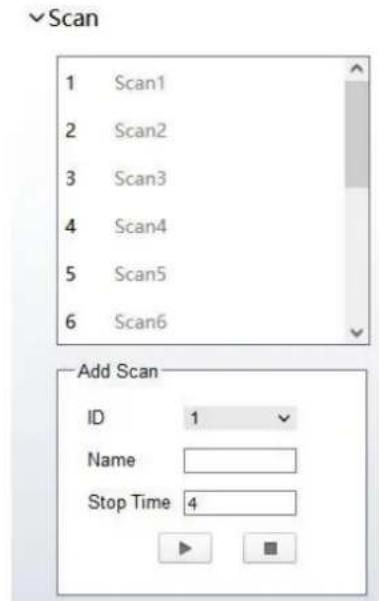
2.4 Configure and Invoke Scans
You can configure a starting point and end point to allow the camera to repeatedly rotate from the starting point to end point.
Step 1
Configure a scan.
- Click Scan.
The Scan Add page is displayed as shown in Figure 2-4.
Figure 2-4 Scan configuration
text_image
Scan 1 Scan1 2 Scan2 3 Scan3 4 Scan4 5 Scan5 6 Scan6 Add Scan ID 1 Name Stop Time 4- Set the scan ID and name.
- Click.
- Use arrow keys in the PTZ Control area to set a start point and an end point.
- Click to finish the scan setting.
Step 2
Invoke a scan.
Select a scan value from the Scan list box, click → to invoke the scan.

NOTE
A maximum of twelve scans can be configured.
2.5 Configure and Invoke Tours
You can configure a tour to allow the camera to repeatedly rotate based the tours. Each tour includes presets and wait time should be set.
Step 1
Configure a tour.
- Click Tour.
The Tour Add page is displayed as shown in Figure 2-5.
Figure 2-5 Tour configuration

text_image
Tour Tour Preset Wait Time Add Tour ID 1 Name Preset Preset1 Wait Time 0- Set the tour ID and name.
- Select a preset and set the wait time and click.
- Continue to select a preset and set the wait time and click √.
- Repeat the step 3 and step 4 to add more presets.
- Click to finish the tour setting.
Step 2
Invoke a tour.
Select a tour value from the tour list box, click → to invoke the tour.

NOTE
A maximum of twelve tours can be configured.
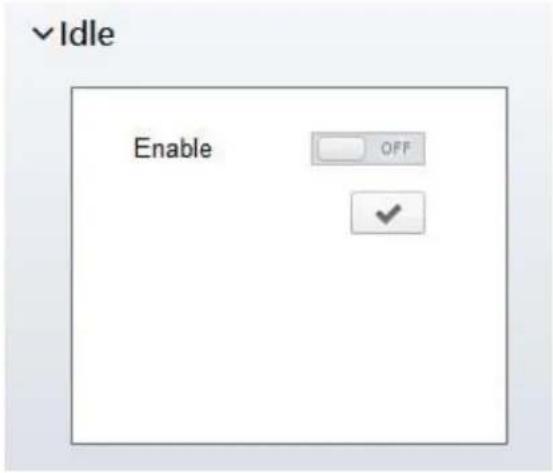
2.6 Configure Idles
You can enable idle to allow the camera to run the preset, track, scan and tour automatically after the waiting time (1 minute \~ 240 minutes).
Step 1 Click Idle.
The Idle Add page is displayed as shown in Figure 2-6.
Figure 2-6 Idle configuration
text_image
√ Idle Enable OFF ✓Step 2 Enable the Idle button.
Step 3 Set the idle type and name from list.
Step 4 Set the wait time(1 min \~240 min).
Step 5 Click √ to finish the idle setting.
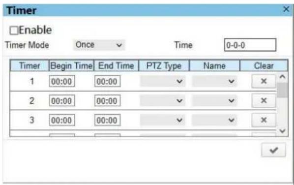
2.7 Configure Timer
You can set the PTZ timer to allow the camera to invoke the preset, track, scan and tour automatically in the setting time and the camera will restore to the operation and location after the end time.
Step 1 Click Timer.
The Set the PTZ Timer page is displayed and click 🙏, the Timer page is displayed as shown in Figure 2-7.
Figure 2-7 Timer configuration
text_image
Timer Enable Timer Mode Once Time 0-0-0 Timer Begin Time End Time PTZ Type Name Clear 1 00:00 00:00 ✓ ✓ ✗ 2 00:00 00:00 ✓ ✓ ✗ 3 00:00 00:00 ✓ ✓ ✗Step 2
Enable Timer.
Step 3 Set the Timer Mode. Timer mode includes Everyday and Once. You should set the time when once mode is selected.
Step 4 Choose Once, click Time to choose day from the pop-up calendar.
Step 5 Set Timers.
Select the begin time, end time, PTZ type and name from the drop-down list box.

NOTE
A maximum of eight timers can be configured.
Click Clear to delete the setting.
Step 6 Click √ to finish the timer setting.
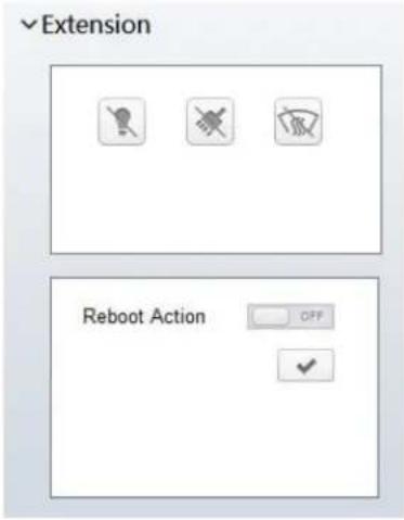
2.8 Configure Extension
You can set light On/Off, brush function and reboot action in extension page.
Click Extension, the Extension page is displayed as shown in Figure 2-8.
Figure 2-8 Extension
text_image
Extension Reboot Action OFFLight function
Click to enable the light.
Light On/Off is used to control the infrared camera shields on and off.
Brush function
Click to enable brush.
Brush is used to clean the lens.

NOTE
Brush is available only to a camera with a brush or a camera shield.
Light On/Off is available only to specific camera shields.
Reboot Action
The camera will perform the selected PTZ type and name when the camera reboots and the reboot action is enabling.
- Click the reboot action button to enable reboot action.
- Set the PTZ Type and name from the drop-down list box.
- Click √ to finish the reboot setting.
---End
3 Image Settings
3.1.1 Access the Image Settings Interface
Operation Procedure:
Step 1 On the web interface, enter Configuration > Image Settings interface.
Figure 3-1 Image Settings Interface
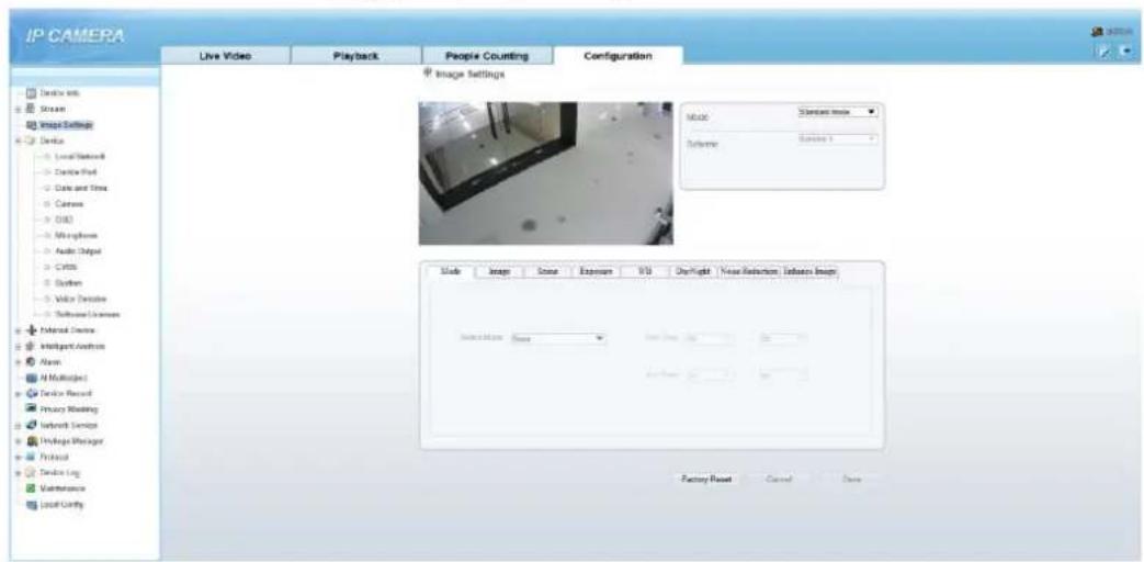
text_image
IP CAMERA Live Video Playback People Counting Configuration Device info Stream Image Settings Device - Local Network - Device Path - Data and Time - Camera - DVD - Wireless - Audio Output - CMOS - System - Video Options - Software Lockers Internal Device Intelligent Analysis Alarms Multiplied Device Record Privacy Monitoring Network Service Wireless Manager Protocol Device Log Maintenance Local Comfy Image Settings Music Standard Image Language Session 1 Mode Image Sound Exposure VSB Overflight Noise Reduction: Effects Image Description: None Text Drop: 0% Audio Drop: 0% Factory Reset Cancel SaveStep 2 Choose Debug Mode on Mode item to set the parameters. You can set four schemes.
---End
3.1.2 Mode
Operation procedure:
Step 1 Click Mode tag on image settings interface, the Mode page is displayed, as shown in Figure 3-2.
Figure 3-2 Mode Page
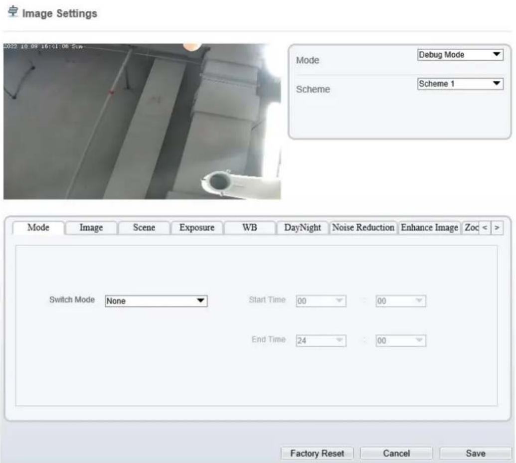
text_image
Image Settings Mode Debug Mode Scheme Scheme 1 Switch Mode None Start Time 00 00 End Time 24 00 Factory Reset Cancel SaveStep 2 Choose Debug Model in the middle left corner to activate the image settings page.
Step 3 Tick the Enable, then set the start time and end time.
Step 4 Click Save to save the setting.
3.1.3 Image Setting
Figure 3-3 shows the image setting interface.
Figure 3-3 Image Setting Interface

text_image
Image Settings Mode Debug Mode Scheme Scheme 1 Mode Image Scene Exposure WB DayNight Noise Reduction Enhance Image Zoc < Brightness - 50 Saturation - 50 Sharpness - 50 Contrast - 50 Factory Reset Cancel SaveTable 3-1 describes the image setting parameters.
Table 3-1 Parameters of Image Settings Parameters
| Parameter | Description | Configuration Method |
| Brightness | It indicates the total brightness of an image. As the value increases, the image becomes brighter. | [Setting method]Drag the slider.[Default value]50 |
| Saturation | It indicates the color saturation of an image. As the value increases, the image becomes more colorful. | [Setting method]Drag the slider.[Default value]50 |
| Sharpness | It indicates the definition of an image. As the value increases, the image becomes more definitional. | [Setting method]Drag the slider.[Default value]50 |
| Contrast | It indicates the contrast between the bright part and the dark part of an image. As the value increases, the contrast increases. | [Setting method]Drag the slider.[Default value]50 |
3.1.4 Scene Mode
Figure 3-4 shows the scene mode interface.
Figure 3-4 Scene Mode Interface for IP Camera
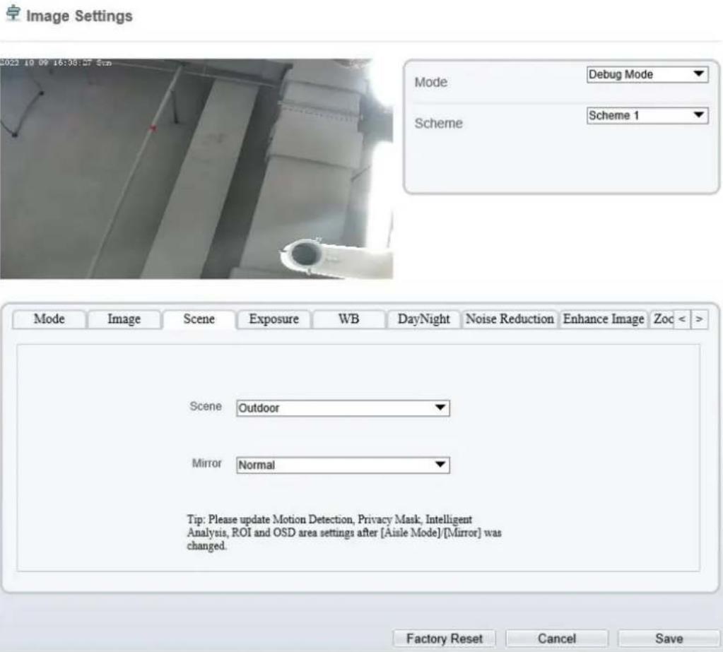
text_image
Image Settings Mode: Debug Mode Scheme: Scheme 1 Scene: Outdoor Mirror: Normal Tip: Please update Motion Detection, Privacy Mask, Intelligent Analysis, ROI and OSD area settings after [Aisle Mode] [Mirror] was changed. Factory Reset Cancel SaveTable 3-2 describes the FFC mode parameters.
Table 3-2 Parameters of FFC
| Parameter | Description | Configuration Method |
| Scene | It indicates the working mode of a camera. Outdoor: It applies to outdoor scenarios. Indoor: It applies to indoor scenarios. | [Configuration method] Select from the drop-down list [Default value] Outdoor |
| Mirror | It is used to select the pixel location of an image.Normal: The image does not flip.Horizontal: The image flips to the left and right.Vertical: The image flips up and down.Horizontal and vertical: The image rotates at 180 degrees. | [Setting method]Select a value from the drop-down list.[Default value]Normal |
| Aisle Mode | The image rotates 90 degrees clockwise when aisle mode is enabled. For some models, when you choose stream 2 / 3, H.265 or H.264 video encode type, resolution chosen CIF or QVGA, it maybe not to play the live video.Only apply for some models. | [Setting method]Tick the Aisle mode.[Default value]Disable |
3.1.5 Exposure
Figure 3-5 and Figure 3-6 shows the Exposure interface.
Figure 3-5 Exposure Interface for IP Camera

text_image
Image Settings 2022-10-19 16:15:16 Wed Mode Debug Mode Scheme Scheme 1 Mode Image Scene Exposure WB DayNight Noise Reduction Enhance Image < Exposure Mode Auto Max Shutter 1/25 Max Gain - + 50 Iris Close Factory Reset Cancel SaveFigure 3-6 Exposure Interface for High-speed Dome
Image Settings
natural_image
Interior view of a dimly lit room with overhead lighting and a person in protective gear (no visible text or symbols)
text_image
Mode Debug Mode Scheme Scheme 1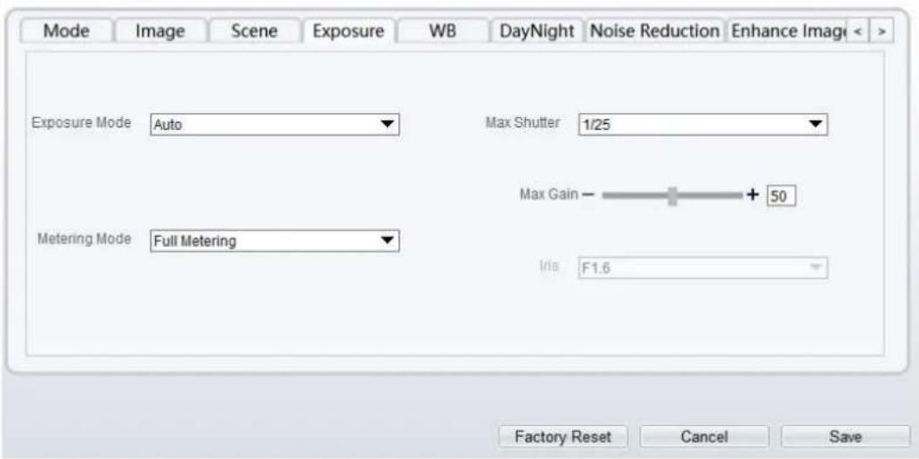
text_image
Mode Image Scene Exposure WB DayNight Noise Reduction Enhance Image Exposure Mode Auto Max Shutter 1/25 Max Gain - + 50 Metering Mode Full Metering Iris F1.6 Factory Reset Cancel SaveTable 3-3 describes Exposure parameters.
Table 3-3 Parameters of Exposure
| Parameter | Meaning | Configuration Method |
| Exposure Mode | The exposure modes include:Auto: The system performs auto exposure based on the monitoring environment.Manual: You can adjust the brightness of an image by setting the following three items:Shutter Setting, Iris Setting and Gain Setting.Shutter Priority: You can set Shutter Setting to fixed values. The iris and gain are automatically adjusted by the system.Iris Priority (for high-speed dome):You can set Iris Setting to fixed values. The shutter and gain are automatically adjusted by the system. | [Setting method]Select a value from the drop-down list.[Default value]Auto |
| Meter Mode | It is used to select the metering area.Fulling Metering: During metering, all areas of an image have equal weight, that is, all areas are involved in the metering.Spot Metering: During metering, the central spot of an image has the highest weight.Partial Metering: During metering, the middle area (1/2 of the total area) of an image has the highest weight, and other areas have the lowest weight. | [Setting method]Select a value from the drop-down list.[Default value]Whole |
| Max Shutter | The device automatically adjusts the shutter time based on the ambient brightness. The shutter time is less than or equal to the value of this parameter. | [Setting method]Select a value from the drop-down list.[Default value]1/25 |
| Max Gain | The device automatically adjusts the gain based on the external light. The gain is less than or equal to the value of this parameter. | [Setting method]Drag the slider.[Default value]50 |
| Iris (for high speed dome) | It is valid in manual mode and iris priority mode. You can adjust the brightness of an image by setting the iris. As the value increases, the brightness increases (when the shutter and gain remain the same).However, the camera movement automatically adjusts the shutter and gain in this mode. Therefore, the brightness of an image may not increase when you increase the iris. | [Setting method]Select a value from the drop-down list.[Default value]F1.6 |
| Iris (for IP camera) | It is used to control the light admitted to the lens.The auto iris can be set to either of the following states:AutoThe iris is automatically adjusted to control the light admitted to the lens.Open fullyThe iris is fully open. | [Setting method]Select a value from the drop-down list.[Default value]Auto |
| Iris Speed | It indicates the auto adjustment speed of the iris. As the value increases, the speed increases. Excessive speed may cause instability.NOTEThis parameter is valid when the auto iris is enabled. | [Setting method]Drag the slider.[Default value]50 |
| Fixed Gain | When the exposure Mode is Manual, you can set the fixed gain. | [Setting method]Drag the slider.[Default value]50 |
3.1.6 WB Setting
Figure 3-7 shows the WB Setting interface.
Figure 3-7 WB Setting Interface
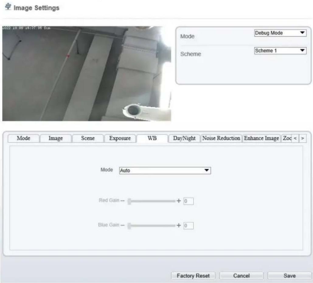
text_image
Image Settings Mode Debug Mode Scheme Scheme 1 Mode Image Scene Exposure WB DayNight Noise Reduction Enhance Image Zoc < Mode Auto Red Gain - + 0 Blue Gain - + 0 Factory Reset Cancel SaveTable 3-4 describes WB Setting parameters.
Table 3-4 Parameters of WB Setting
| Parameter | Meaning | Configuration Method |
| Mode | Select WB mode according to different scenes for better image color reproduction.Auto: In automatic white balance (WB) mode, the system automatically performs white balance based on the monitoring environment.TungstenFluorescentDaylightShadowManual: In manual WB mode, you can manually select a WB mode based on the monitoring environment. | [Setting method]Select a value from the drop-down list.[Default value]Auto |
| Red Gain | It indicates the gain applied to red channels. As the value increases, the color temperature becomes lower.NOTEThis parameter is valid when Manual Mode is set to Customized. | [Setting method]Drag the slider.[Default value]0 |
| Blue Gain | It indicates the gain applied to blue channels. As the value increases, the color temperature becomes higher.NOTEThis parameter is valid when Manual Mode is set to Customized. | [Setting method]Drag the slider.[Default value]0 |
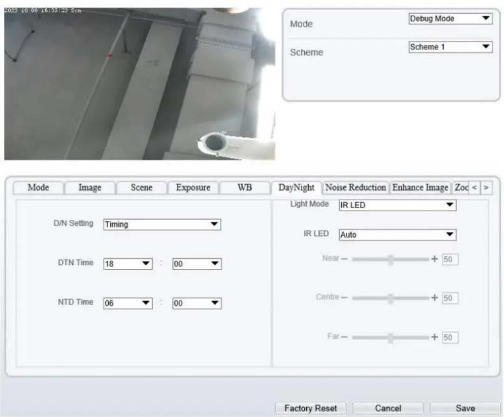
3.1.7 DayNight
The day night mode settings vary based on device models. For details, see the following sections.
Figure 3-8 shows the DayNight Mode interface.
Figure 3-8 DayNight Mode Interface
Image Settings
text_image
2022 10 09 16:35:25 5cm Mode Debug Mode Scheme Scheme 1 Mode Image Scene Exposure WB DayNight Noise Reduction Enhance Image Zoc < Light Mode IR LED IR LED Auto D/N Setting Timing DTN Time 18 : 00 NTD Time 06 : 00 Near - + 50 Centre - + 50 Far - + 50 Factory Reset Cancel SaveTable 3-5 describes DayNight Mode parameters.
Table 3-5 Parameters of DNR
| Parameter | Meaning | Configuration Method |
| D/N Setting Mode | It can be set toAuto, Day, NightorTiming.Auto modeThe image color and filter status are automatically switched based on the ambient brightness. The filter keeps infrared light from reaching the sensor during the day; The filter allows all light to reach the sensor at night.Day modeThe image is colored, and the filter is in the day state, preventing infrared light from entering the sensor.Night modeThe image is black and white, and the filter is in the night state, allowing infrared light to enter the sensor.TimingSwitching between day mode and night mode according to the set time. | [Setting method]Select a value from the drop-down list.[Default value]Auto |
| Switch Sensitivity | The sensitivity of switching day and night. The higher value of sensitivity, and the lower light intensity will switch to day.NOTEThis parameter is valid in auto mode. | [Setting method]Drag the slider.[Default value]50 |
| TRANSI.(D->N) (dB) | It determines the day-to-night switching in auto mode. When the system gain is greater than the value of this parameter, the system enters the night mode.NOTEThis parameter is valid in auto mode. The value of TRANSI. (D->N) must be greater than the value of TRANSI. (N->D). | [Setting method]Drag the slider.[Default value]70 |
| TRANSI.(N->D) (dB) | It determines the night-to-day switching in auto mode. When the system gain is smaller than the value of this parameter, the system enters the day mode.NOTEThis parameter is valid in auto mode. The value of TRANSI.(D->N) must be greater than the value of TRANSI.(N->D). | [Setting method]Drag the slider.[Default value]30 |
| Delay(s) | The delay time of day to night or night to day.NOTEThis parameter is valid in auto mode. | [Setting method]Drag the slider.[Default value]0 |
| Light Mode | For different models, you can choose the light modes, such as IR LED, White LED, Intelligent dual light (there are two lights in camera, IR LED and white LED), and none. It depends on performance of cameras. | [Setting method]Select a value from the drop-down list. |
| IR LED | Auto: The infrared lamp is enabled or disabled based on the external environment identified by the light dependent resistor (LDR).ON: The system enters the night mode forcibly.OFF: The infrared lamp is disabled. The filter and image color are switched based on the external environment identified by the LDR.NOTEThis parameter is valid in auto mode. | [Setting method]Select a value from the drop-down list.[Default value]Auto |
| Strength | Strength of IR LED, as the value increases, the image becomes brighter. | [Setting method]Drag the slider.[Default value]50 |
| DTN Time | Time of day to night. | [Setting method]Select a value from the drop-down list.[Default value]18:00 |
| NTD Time | Time of night to day. | [Setting method]Select a value from the drop-down list.[Default value]6:00 |
Fill light settings
The camera fill light has four modes, there is intelligent dual light (the current fill light will switch to warm light after an alarm is triggered, and switch back to the original fill light for fill light 30s after the alert is released.), warm light, infrared lamp and close (Choose to close the fill light and the color of image will stay in the previous mode).
Different cameras can be set in different fill light modes, please set them according to the actual scene.
Day mode: It can be used in the scene with sufficient ambient light for 24 hours, do not turn on the fill light, and the image is in color.
Night mode: it can be used in a scene where there is insufficient ambient light for 24 hours, turn on the fill light (it can be selected according to the four modes of the fill light).
Auto mode: Automatically switch the set fill light mode according to the brightness of the environment.
Timing mode: Set the start and end time of the day, this time period is in day mode.
The brightness of the fill light can be selected between automatic and manual, automatic mode is meaning it can be adjusted automatically according to the current environment; manual mode, you can scroll to check or set the value to control.
3.1.8 Noise Reduction
Figure 3-9 shows the Noise Reduction interface.
Figure 3-9 Noise Reduction Interface (auto)
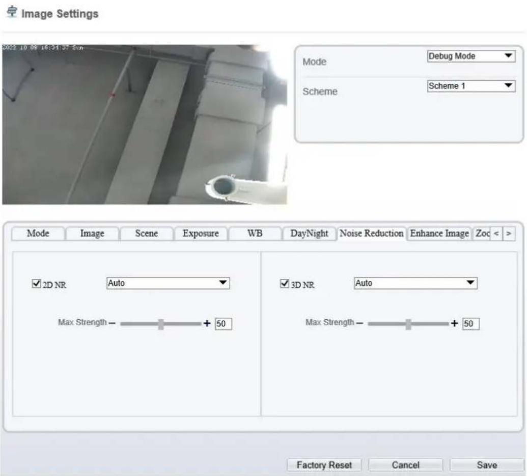
text_image
Image Settings Mode Debug Mode Scheme Scheme 1 Mode Image Scene Exposure WB DayNight Noise Reduction Enhance Image Zoc 2D NR Auto Max Strength - + 50 3D NR Auto Max Strength - + 50 Factory Reset Cancel SaveFigure 3-10 Noise Reduction Interface (manual)
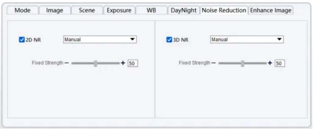
text_image
Mode Image Scene Exposure WB DayNight Noise Reduction Enhance Image ✓ 2D NR Manual ✓ 3D NR Manual Fixed Strength - + 50 Fixed Strength - + 50Table 3-6 describes DNR parameters.
Table 3-6 Parameters of DNR Parameters
| Parameter | Meaning | Configuration Method |
| 2D NR | Reduce noise of image. | [Configuration method]Select from the drop-down list[Default value]Auto |
| 3D NR | Reduce noise of image. | [Configuration method]Select from the drop-down list[Default value]Auto |
| Max Strength | It is valid in auto noise filter mode. When the parameter value is 0, the noise filter is disabled. When the parameter value is greater than 0, the noise filter is enabled, and the system automatically adjusts the noise filter level based on the ambient brightness without exceeding the value of this parameter. | [Setting method]Drag the slider.[Default value]50 |
| Fixed Strength | It is valid in a manual noise filter mode. | [Setting method]Drag the slider.[Default value]50 |
3.1.9 Enhance Image
Figure 3-11 shows the enhance image interface and Table 3-7 shows the enhance image parameters.
Figure 3-11 Enhance Image Interface

text_image
Image Settings 2022 10 09 16:33:58 5th Mode Debug Mode Scheme Scheme 1 Mode Image Scene Exposure WB DayNight Noise Reduction Enhance Image Zoc < WDR - + 50 Anti-shake HLC - + 50 Defog - + 50 BLC - + 50 Factory Reset Cancel SaveTable 3-7 Parameters of Enhance Image
| Parameter | Meaning | Configuration Method |
| WDR | It is used to display the foreground and background at the same time in the environment with a large brightness difference. When the brightness difference is larger, you can increase the WDR level to obtain better image effect. | [Setting method]Tick the WDR mode and drag the slider.[Default value]50 |
| HLC | It provides a clearer view of an image in the highlight environment. When HLC is enabled, the total brightness of an image is reduced, allowing you to view objects in front of the highlight. | [Setting method]Tick the HLC mode and drag the slider.[Default value]50 |
| BLC | It provides a clearer view of an image in the backlight environment. When BLC is enabled, the total brightness of an image increases, allowing you to view objects in front of the backlight. Meanwhile, the objects behind the backlight are exposed excessively. | [Setting method]Tick the BLC mode and drag the slider.[Default value]50 |
| Anti-shake | The shakes and visual angle of image will reduce when the camera shakes slightly and the anti-shake is enable. | [Setting method]Tick the Anti-shake mode. |
| DeFog | It provides a clearer view of an image in the fogged environment when DeFog is enabled.As the value increases, the image becomes clearer. | [Setting method]Tick the Defog mode and drag the slider.[Default value]50 |
3.1.10 Zoom Focus (Only for Some Models)
Figure 3-12 and Figure 3-13 shows the zoom focus interface and Table 3-7 shows the zoom focus parameters.
Figure 3-12 Zoom Focus Interface for IP Camera
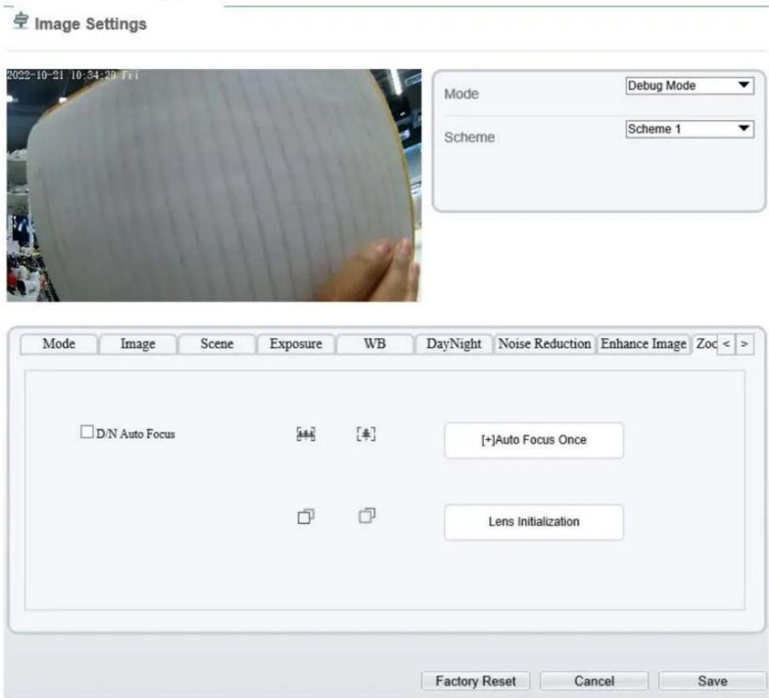
text_image
Image Settings 2022-10-21 10:34:20 Fri Mode Debug Mode Scheme Scheme 1 Mode Image Scene Exposure WB DayNight Noise Reduction Enhance Image Zoc < D/N Auto Focus [+] [*] [+]Auto Focus Once Lens Initialization Factory Reset Cancel SaveImage Settings
natural_image
Interior view of a room with concrete walls and a pipe, no visible text or symbols
text_image
Mode Debug Mode Scheme Scheme 1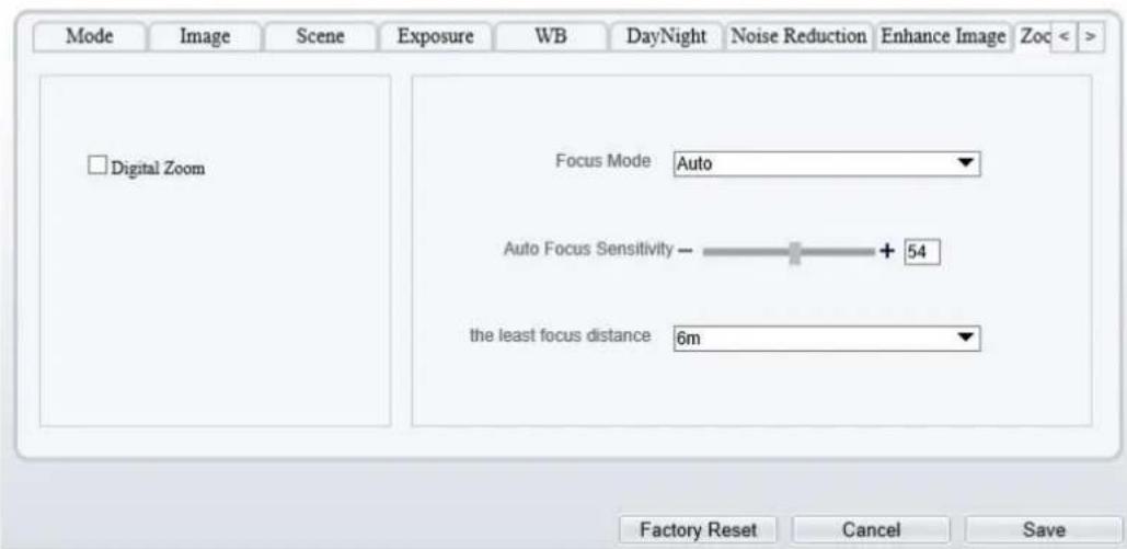
text_image
Mode Image Scene Exposure WB DayNight Noise Reduction Enhance Image Zoc < Digital Zoom Focus Mode Auto Auto Focus Sensitivity - + 54 the least focus distance 6m Factory Reset Cancel SaveFigure 3-13 Zoom Focus Interface for High Speed Dome
Image Settings

natural_image
Interior ceiling view of a room with recessed lighting and no visible text or symbols
text_image
Mode Debug Mode Scheme Scheme 1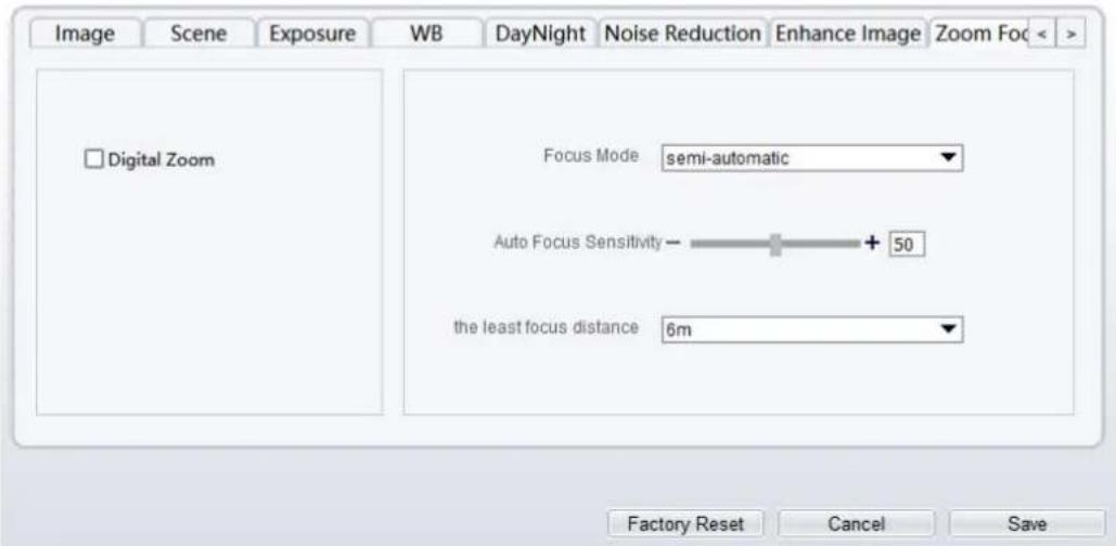
text_image
Image Scene Exposure WB DayNight Noise Reduction Enhance Image Zoom Foc < Digital Zoom Focus Mode semi-automatic Auto Focus Sensitivity - 50 the least focus distance 6m Factory Reset Cancel SaveTable 3-8 Parameters of Zoom Focus
| Parameter | Meaning | Configuration Method |
| D/N Auto Focus | It is used to trigger auto focus when day to night or night to day. | [Setting method]Tick the Auto focus. |
| Auto Focus Once | Click to trigger once auto focus. | [Setting method]Click the button. |
| Int | The lens of camera returns to the initial position. | [Setting method]Click the button. |
| Digital | This function enables digital zoom after an image is zoomed in by 37 times in optical mode. | [Setting method]Tick the Digital. |
| Focus Mode | It can be set to the auto, manual or semi-automatic mode.Auto focus mode: The system automatically triggers focus based on application scenarios.Manual focus mode: You can trigger focus by using the buttons on the client.Semi-automatic focus mode: The system only automatically trigger focus once when the PTZ move or zoom in a scene. | [Configuration method]Select from the drop-down list [Default value]Semi-automatic |
| Auto Focus Sensitivity | It indicates the sensitivity of auto focus.When the sensitivity is high, the camera movement is more likely to focus again at slight changes of an image. | [Setting method]Drag the slider.[Default value]50 |
| The Least Focus Distance | It indicates the minimum focus distance. A camera does not focus when the distance is smaller than this value. For example, if the minimum focus distance is set to 1.5 m, a camera focuses only on objects more than 1.5 m away, and the changes of objects less than 1.5 m away do not affect the focusing.NOTEThis parameter applies only to visible light. | [Configuration method]Select from the drop-down list [Default value]3 m |
---End
4 Configure the Device
4.1 Device Information
Description
The device information includes:
Device ID, name, type, model, manufacturer name and MAC address.
Hardware and software versions.
Number of video channels, number of alarm input channels, number of alarm output channels, and number of serial ports, network cards.

NOTE
You can modify the device name. All other parameters can only be viewed.
When the device is upgraded, the device information is updated automatically.
Procedure
Step 1 Click Configuration > Device Info.
The Device Info page is displayed, as shown in Figure 4-1.
Figure 4-1 Device Info Page

Device Info

text_image
Device ID 547577 Device Name MAC Address 00:1C:27:54:75:77| Camera Type | AI_MULTIOBJECT |
| Product Model | SN-IPV8080EFAR-B2.8-23 |
| Manufacturer Name | IPCamera |
| Hardware Version | V220014_5 |
| Firmware Version | v3.6.1603.1004.3.0.11.1.0.D01 |
| Uboot Version | v1.2 |
| Kernel Version | v2.1_PDTJul |
| Channel Quantity | 1 |
| Alarm Input Quantity | 1 |
| Alarm Output Quantity | 1 |
| Serial Port Quantity | 0 |
| Network Card Quantity | 1 |
Refresh
Step 2 View the device information, set the device name according to Table 4-1.
Table 4-1 Parameters of Device
| Parameter | Description | Setting |
| Device ID | Unique device identifier used by the platform to distinguish the devices. | [Setting method]The parameter cannot be modified. |
| Device Name | Name of the device.NOTEThe device name cannot exceed 32 bytes or 10 simplified characters; otherwise, the modification fails. | [Setting method]Enter a value manually. |
| MAC Address | N/A | [Setting method]These parameters cannot be modified. |
| Camera Type | ||
| Product Model | ||
| Manufacturer Name | ||
| Hardware Version | ||
| Firmware Version | ||
| Uboot version | ||
| Kernel version | ||
| Video Channel(s) | ||
| Channel Quantity | ||
| Alarm Input Quantity | ||
| Alarm Output Quantity | ||
| Serial Port Quantity | ||
| Network card Quantity |
Step 3

Click.
If the message "Apply success!" is displayed, click OK. The system saves the settings.
If the message "Apply failed!" is displayed, you must apply for the Parameter Configure permission from an administrator. For details, see 14.1 Configure a User.
---End
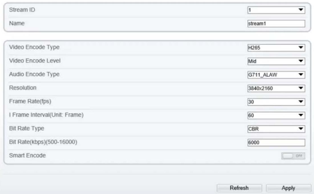
4.2 Video and Audio Stream
Procedure
Step 1 Click Configuration > Stream > Base Stream.
The Stream Configuration page is displayed, as shown in Figure 4-2.
Figure 4-2 Stream Configuration Page (CBR)

Stream
text_image
Stream ID 1 Name stream1 Video Encode Type H265 Video Encode Level Mid Audio Encode Type G711_ALAW Resolution 3840x2160 Frame Rate(fps) 30 I Frame Interval(Unit: Frame) 60 Bit Rate Type CBR Bit Rate(kbps)(500-16000) 6000 Smart Encode OFF Refresh Apply
Stream
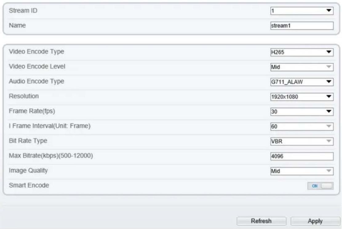
text_image
Stream ID 1 Name stream1 Video Encode Type H265 Video Encode Level Mid Audio Encode Type G711_ALAW Resolution 1920x1080 Frame Rate(fps) 30 I Frame Interval(Unit: Frame) 60 Bit Rate Type VBR Max Bitrate(kbps)(500-12000) 4096 Image Quality Mid Smart Encode ON Refresh ApplyStep 2 Set the parameters according to Table 4-2.
Table 4-2 Parameters of Stream Configuration
| Parameter | Description | Setting |
| Stream ID | The device supports at most three main streams. Streams 1 and 2 adopt H.264 code.The maximum resolution can be set for streams 1.Only a low resolution can be set for stream 2.Stream 3 is the lowest resolution.Stream 4 is the sub stream. | [Setting method]Select a value from the drop-down list box. |
| Name | Stream name.NOTEThe stream name consists of Chinese character, number, character and underline. | [Setting method]Enter a value manually. The value cannot exceed 32 bytes.[Default value]Stream 1 |
| Video Encode yT | The video codec determines the image quality and network bandwidth required by a video. Currently, the following codec standards are supported:MJPEGMJPEG is a standard intra-frame compression codec. The compressed image quality is good. No mosaic is displayed on motion images. MJPEG does not support proportional compression and requires large storage space. Recording and network transmission occupy large hard disk space and bandwidth. MJPEG is not applicable to continuous recording for a long period of time or network transmission of videos. It can be used to send alarm images.H.264H.264 consists of H.264 low Profile, H.264 Main Profile and H.264 High profile. The performance of H.264 High Profile is higher than that of H.264 Main Profile, and the performance of H.264 Main Profile is higher than that of H.264 Base Profile. If a hardware decoding device is used, select the appropriate codec based on the decoding performance of the device.H.264 High Profile has the highest requirements on the hardware performance, and H.264 Base Profile has the lowest requirements for the hardware performance.H.265H.265 is the advanced video encoding standard. It's the improvement standard from H.264. H.265 improves the streams, encoding quality and algorithm complexity to make configuration optimization. | [Setting method]Select a value from the drop-down list box.[Default value]H.264 High ProfileNOTEThe H.264 High Profile codec means high requirements on the hardware. If the hard-decoding capability is low, use H.264 Main Profile or H.264 Base Profile.When users choose the MJPEG for Stream 1, some functions will be error, such as the videos of FTP upload may not be play correctly. |
| Audio Encode Type | The following audio codec standards are supported:G711_ULAW: mainly used in North America and Japan.G711_ALAW: mainly used in Europe and other areas.RAW_PCM: codec of the original audio data.This codec is often used for platform data. | [Setting method]Select a value from the drop-down list box. |
| Resolution | A higher resolution means better image quality.NOTEIP cameras support the different resolutions based on the model. | [Setting method]Select a value from the drop-down list box. |
| Frame Rate(fps) | Frame rate is the number of images, shots, or frames that a camera can take per second. The frames per second determine the smoothness of a video. A video whose frame rate is higher than 22.5 f/s is considered as smooth by human eyes.Frame rates for different frequencies are as follows:50 Hz: 1–25 f/s60 Hz: 1–30 f/sNOTEThe frequency is set on theDevice Configuration >Camera page. The biggest MJPEG coding format frame rate is 12 frames per second. | [Setting method]Select a value from the drop-down list |
| I Frame Interval(f) | I frame do not require other frames to decode.A smaller I frame interval means better video quality but higher bandwidth. | [Setting method]Select a value from the drop-down list |
| Bit Rate Type | The bit rate is the number of bits transmitted per unit of time.The following bit rate types are supported:Constant bit rate (CBR)The compression speed is fast; however, improper bit rate may cause vague motion images.Variable bit rate (VBR)The bit rate changes according to the image complexity. The encoding efficiency is high and the definition of motion images can be ensured. | [Setting method]Select a value from the drop-down list box. |
| Max Bitrate (500-12000) | Indicates the maximal value of the bit rate. the different models may have different ranges, please refer to actual product. | [Setting method]Enter a value manually. |
| Image Quality | The video quality the camera output. | [Setting method]Select a value from the drop-down list box. |
| Smart Encode | Smart Encode. Smart encode includes H.264 & H.265. The storage space will be reduced fifty percent when smart encode is enabled. Only main stream supports smart encode. | [Setting method] Click the button on to enable Smart Encode. |
Step 3 Click Apply.
If the message "Apply success!" is displayed, and the system saves the settings.
If the message "Apply failed!" is displayed, you must apply for the Parameter Configure permission from an administrator. For details, see 14.1 Configure a User.
If a message indicating that the bit rate invalid is displayed, enter a new bit rate value.
---End
4.3 ROI Parameter
Procedure
Step 1 Click Configuration > Stream > ROI.
The ROI page is displayed, as shown in Figure 4-3.
Figure 4-3 ROI Configuration Page

ROI

text_image
Channel 1 Stream 1 Enable ON Area ID 1 Level 5 Area Name 2515 Note: Max size50% ;Right click to remove the zones drawn Draw Clear Refresh ApplyStep 2 Set the parameters according to Table 4-3.
Table 4-3 Parameters of ROI
| Parameter | Description | Setting |
| Stream | Stream ID. | [Setting method]Select a value from the drop-down list box.[Default value]Stream 1 |
| Enable | Enable the ROI | [Setting method]Click the button.[Default value]OFF |
| Area ID | ROI area ID | [Setting method]Select a value from the drop-down list box.[Default value]1 |
| Level | The visual effect of ROI. The higher the level is, the clearer the area is; the more blurred outside the area. | [Setting method]Select a value from the drop-down list box.[Default value]5 |
| Area Name | The marked name used for areas. | [Setting method]Enter a value manually. The value cannot exceed 32 bytes. |
Step 3 Click Draw to show the red frame, drag the four corners of rectangle to adjust the position.
Step 4 Click Apply.
The message "Apply success!" is displayed, and the system saves the settings.
---End
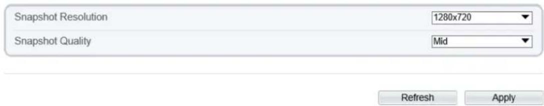
4.4 Snapshot
Procedure
Step 1 Click Configuration > Stream > Snapshot.
The ROI page is displayed, as shown in Figure 4-4.
Figure 4-4 Snapshot Configuration Page

Snapshot
text_image
Snapshot Resolution 1280x720 Snapshot Quality Mid Refresh ApplyStep 2 Set the parameters according to Table 4-3.
Table 4-4 Parameters of Snapshot Configuration
| Parameter | Description | Setting |
| Snapshot Resolution | Choose resolution of snapshot. | [Setting method]Select a value from the drop-down list box.[Default value]1280*720 |
| Snapshot Quality | Choose the quality of snapshot. | [Setting method]Click the button.[Default value]Mid |
----End
4.5 Local Network
Description
Local network parameters include:
IP protocol
IP address
Subnet mask
Default gateway
Dynamic Host Configuration Protocol (DHCP)
Preferred Domain Name System (DNS) server
Alternate DNS server
MTU
Procedure
Step 1 Choose Configuration > Device > Local Network.
The Local Network page is displayed, as shown in Figure 4-5.
Figure 4-5 Local Network Page
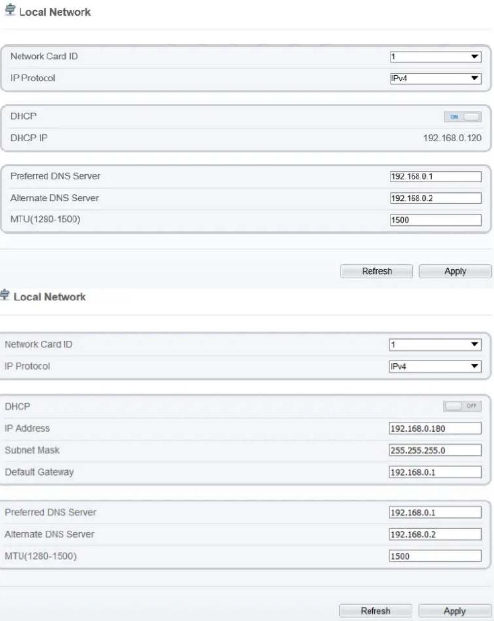
text_image
Local Network Network Card ID 1 IP Protocol IPv4 DHCP DHCP IP 192.168.0.120 Preferred DNS Server 192.168.0.1 Alternate DNS Server 192.168.0.2 MTU(1280-1500) 1500 Refresh Apply Local Network Network Card ID 1 IP Protocol IPv4 DHCP OP IP Address 192.168.0.180 Subnet Mask 255.255.255.0 Default Gateway 192.168.0.1 Preferred DNS Server 192.168.0.1 Alternate DNS Server 192.168.0.2 MTU(1280-1500) 1500 Refresh ApplyStep 2 Set the parameters according to Table 4-5.
Table 4-5 Local Network Parameters
| Parameter | Description | Setting |
| Network Card ID | -- | [Default value]1 |
| IP Protocol | IPv4 is the IP protocol that uses an address length of 32 bits. | [Setting method]Select a value from the drop-down list box.[Default value]IPv4 |
| Obtain IP address automatically | The device automatically obtains the IP address from the DHCP server. | [Setting method]Click the button on to enable obtain IP address automatically.NOTETo query the current IP address of the device, you must query it on the platform based on the device name. |
| DHCP IP | IP address that the DHCP server assigned to the device. | N/A |
| IP Address | Device IP address that can be set as required. | [Setting method]Enter a value manually.[Default value]192.168.0.120 |
| Subnet Mask | Subnet mask of the network adapter. | [Setting method]Enter a value manually.[Default value]255.255.255.0 |
| Default Gateway | This parameter must be set if the client accesses the device through a gateway. | [Setting method]Enter a value manually.[Default value]192.168.0.1 |
| Preferred DNS Server | IP address of a DNS server. | [Setting method]Enter a value manually.[Default value]192.168.0.1 |
| Alternate DNS Server | IP address of a domain server.If the preferred DNS server is faulty, the device uses the alternate DNS server to resolve domain names. | [Setting method]Enter a value manually.[Default value]192.168.0.2 |
| MTU | Set the maximum value of network transmission data packets. | [Setting method]Enter a value manually.NOTEThe MTU value is range from 1280 to 1500, the default value is 1500, Please do not change it arbitrarily. |
Step 3 Click Apply.
If the message "Apply success!" is displayed, and the system saves the settings. The message "Set network parameter success, Please login system again" is displayed. Use the new IP address to login to the web management system.
If the message "Invalid IP Address", "Invalid Subnet Mask", "Invalid default gateway", "Invalid primary DNS", or "Invalid space DNS" is displayed, set the parameters correctly.
---End
4.6 Device Port
Description
You must configure the HTTP port, control port, Real Time Streaming Protocol (RTSP) port and SSL Control port for device route mapping in a LAN.
Procedure
Step 1 Choose Configuration > Device > Device Port.
The Device Port page is displayed, as shown in Figure 4-6.
Figure 4-6 Device Port Page

Device Port
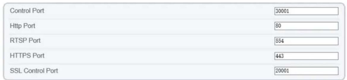
text_image
Control Port 30001 Http Port 80 RTSP Port 554 HTTPS Port 443 SSL Control Port 20001Refresh Apply

Device Port
text_image
Control Port(1025-65535) 30001 HTTP Port(1-65535) 80 RTSP Port(1-65535) 554 HTTPS Port(1-65535) 443Refresh Apply
Step 2 Set the parameters according to Table 4-6.
Table 4-6 Device PoParameters
| Parameter | Description | Setting |
| Control Port | Port used for audio and video transfer and signaling interaction. | [Setting method]Enter a value manually.[Default value]30001 |
| HTTP Port | Port used in web access. | [Setting method]Enter a value manually.[Default value]80 |
| RTSP Port | RTSP protocol port. | [Setting method]Enter a value manually.[Default value]554 |
| HTTPS Port | Hyper Text Transfer Protocol over Secure Socket Layer | [Setting method]Enter a value manually.[Default value]443 |
| SSL Control Port | Secure socket layer control port.Only for Some Models. | [Setting method]Enter a value manually.[Default value]20001 |

NOTE
It's not recommended to modify the control port, for details about the value ranges of the control port, HTTP port and SSL Control port, see the communication matrix.
Step 3 Click Apply.
If the message "Apply success!" is displayed, and the system saves the settings.
If the message "Invalid Control Port, please input an integer between 1025 and 65535" is displayed, enter correct port numbers.
---End
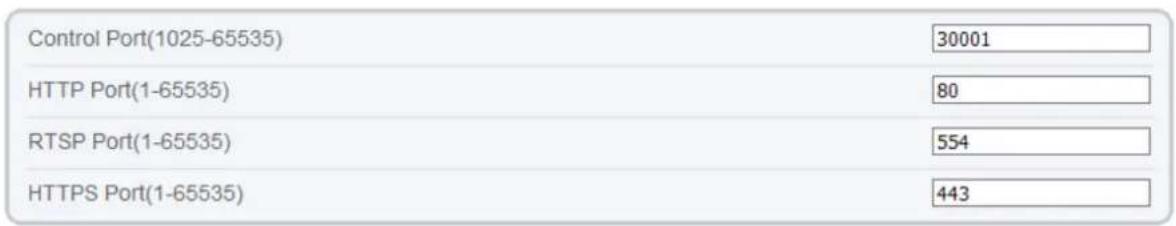
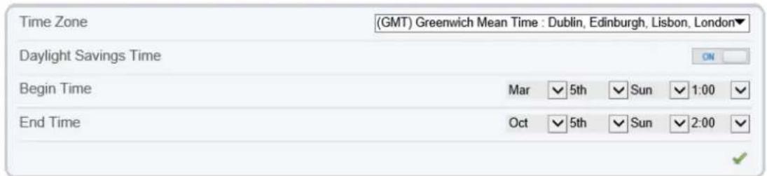
4.7 Date and Time
Description
On the Date and Time page, you can modify the date and time. Parameters that can be set include:
Time zone and daylight-saving time (DST)
Date and time
Network Time Protocol (NTP) server
Procedure
Step 1 Choose Configuration > Device > Date and Time.
The Date and Time page is displayed, as shown in Figure 4-7. Table 4-7 describes the parameters.
Figure 4-7 Date and Time Page
Date and Time
text_image
Time Zone (GMT) Greenwich Mean Time : Dublin, Edinburgh, Lisbon, London▼ Daylight Savings Time ON Begin Time Mar 5th Sun 1:00 End Time Oct 5th Sun 2:00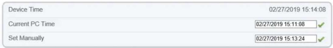
text_image
Device Time 02/27/2019 15:14:08 Current PC Time 02/27/2019 15:11:08 Set Manually 02/27/2019 15:13:24
text_image
NTP NTP Server Addr NTP Port 123 Check the time interval(greater than 10s) 3600
Table 4-7 Date and Time Parameters
| Parameter | Description | Setting |
| Time Zone | N/A | [Setting method]Select a value from the drop-down list box.[Default value]Greenwich mean time |
| Daylight Saving Time | When the DST start time arrives, the device time automatically goes forward one hour. When the DST end time arrives, the device time automatically goes backward one hour.NOTEDST is the practice of advancing clocks so that evenings have more daylight and mornings have less. Currently, about 110 countries in the world use DST. Different countries have different DST provisions. Since March 27, 2011, Russia has started to use permanent DST. | [Setting method]Click the button on to enable Daylight Saving Time. |
| Device Time | Device display time. | [Setting method]Synchronize the time from the PC.Enter a value manually. |
| Current PC Time | Time on the current PC. | N/A |
| Set Manually | Enables you to manually set the device time. | [Setting method]Click Set Manually and set the date and time in the format YYYY-MM-DDHH:MM: SS. |
| NTP | IP address or domain name of the NTP server. | [Setting method]Click the button on to enable NTP and enter a value manually. |
| NTP Server Addr | The NTP server IP. | [Setting method]Enter a value manually. |
| NTP Port | Port number of the NTP server. | [Setting method]Enter a value manually.[Default value]123 |
| Check the time interval (at least 10 s) | Set time interval to check if the device time synchronizes with the NTP server time. | [Setting method]Enter a value manually.[Default value]3600 |
Step 2 Select a time zone from the Time Zone drop-down list box.
Step 3 (Optional) Click the button on to enable Daylight Saving Time and specify the DST start time and end time.
Step 4 Modify the device time.
Synchronizing time from the PC
Click Current PC Time.
Manually setting the device time
- Click Set Manually.
- A time setting control is displayed.
- Set the date and time.
Step 5 Configure the NTP.
- Click the button on to enable NTP.
- Enter the IP address or domain name of the NTP server, the port number and the time interval.
Step 6 Click √.
The message "Apply success!" is displayed and the system saves the settings.
----End
4.8 Camera
Procedure
Step 1 Choose Configuration > Device > Camera.
The Camera page is displayed, as shown in Figure 4-8. Table 4-8 describes the parameters.
Figure 4-8 Camera Page

text_image
Camera Video System NTSC Video Refresh Frequency 60 RefreshTable 4-8 Camera parameters
| Parameter | Description | Setting |
| Video System | The options are as follows:PAL: Used in Europe and China mainland, India, Pakistan, etc.NTSC: Used in USA, Japan, South Korea, and Taiwan Province of China, etc. | [Setting method]Select a value from the drop-down list box.[Default value]PALNOTEWhether the video system can be changed depends on the device model. |
| Video Refresh Frequency | The options are as follows:50 Hz: corresponds to the PAL system.60 Hz: corresponds to NTSC system. | [Setting method]Follow the video standard. |
Step 2
Enter a channel name.

NOTE
The channel name must be within the length of 0 to 32 bytes, it is combined with digital and character (except for some special character, such as < > % \& , = + | ).
Step 3 Click

The message "Apply success!" is displayed.

NOTE
If the video system is modified, the message "The device will be restart, are you sure to modify?" is displayed, and the system automatically saves the settings. The settings take effect after the device restarts.
---End
4.9 OSD
Description
The on-screen display (OSD) function allows you to display the device name, channel ID and name, time, and other customized contents on videos. You can drag the OSD frames to anywhere you want to put.
When the resolution is D1 and CIF, the OSD customized in web interface can show at most 22 words normally.
The OSD support simplified Chinese, English, digital and some special character only.
Procedure
Step 1 Choose Configuration > Device > OSD.
The OSD page is displayed, as shown in Figure 4-9.
Figure 4-9 PTZ OSD Page

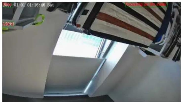
text_image
2003-01-01 01:16:46 Sat 120+1 Focusing on the site
text_image
Align Left▼ Time Align Left▼ Focusing on the state Custom OSD Align Left▼ 120*4 Align Left▼ Align Left▼ Align Left▼ Align Left▼ Align Left▼ Align Left▼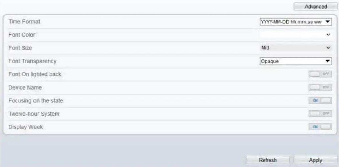
text_image
Time Format YYYY-MM-DD hh:mm:ss ww Font Color Font Size Mid Font Transparency Opaque Font On lighted back OFF Device Name OFF Focusing on the state ON Twelve-hour System OFF Display Week ON Refresh Apply Advanced

text_image
Time3-02-28 11:44:16 Tues P1Z Position P1Z -300 P1Z Temperature Timer display off home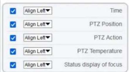
text_image
Align Left▼ Time Align Left▼ PTZ Position Align Left▼ PTZ Action Align Left▼ PTZ Temperature Align Left▼ Status display of focus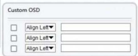
text_image
Custom OSD Align Left▼ Align Left▼ Align Left▼
text_image
Time Format YYYY-MM-DD hh:mm:ss ww Font Color Font Size Mid Font Transparency Opaque Font On lighted back OFF Device Name OFF PTZ Position ON PTZ Action ON PTZ Temperature ON Status display of focus ON Twelve-hour System OFF Display Week ON Refresh ApplyStep 2 Set the parameters according to Table 4-9.

NOTE
There are at most seven OSD display areas..
Table 4-9 OSD Parameters
| Parameter | Description | Setting |
| Time | Indicates whether to display the time. | [Setting method]Tick the time. |
| Focusing on the State | Displays the state of focusing on.NOTE:Only Supplied for camera of auto focusing lens. | [Setting method]Tick the Focusing on the state. |
| Custom OSD | Enables you to enter a line of characters. | [Setting method]1. Tic list.2. Ent Click to save the value. |
| Time Format | Format in which the time is displayed. | [Setting method]Select a value from the drop-down list box.[Default value]YYYY-MM-DD hh:mm:ss ww |
| Font Color | Set the font color. | [Setting method]Select a value from the drop-down list box.[Default value]Blank |
| Font Size | Set the font size. | [Setting method]Select a value from the drop-down list box.[Default value]Mid |
| Font Transparency | Set the font transparency. | [Setting method]Select a value from the drop-down list box.[Default value]Opaque |
| Font on Lighted Back | Enable the font on lighted back. | [Setting method]Click the button on to enable Font on lighted back. |
| Device Name | Indicates whether to display the device name. | [Setting method]Click the button on to enable Device Name |
| PTZ Position | Only used for PTZ cameras | [Setting method]Click the button on to enable |
| PTZ Action | [Setting method]Click the button on to enable | |
| PTZ Temperature | [Setting method]Click the button on to enable | |
| Status Display of Focus | The status of focusing will be showing on live video. | [Setting method]Click the button on to enable |
| Twelve-hour System | The time format shows at twelve-hour system. | [Setting method]Click the button on to enable |
| Display Week | The week will show. | [Setting method]Click the button on to enable |
Step 3 Click Advanced, set the parameter of “Time Format”, “Font Color”, “Font Transparency”, “Font on lighted back”, and so on.
Step 4 Click Apply.
The message "Apply success!" is displayed And the system saves the settings.
---End
4.10 Audio Input (Only for Some Models)
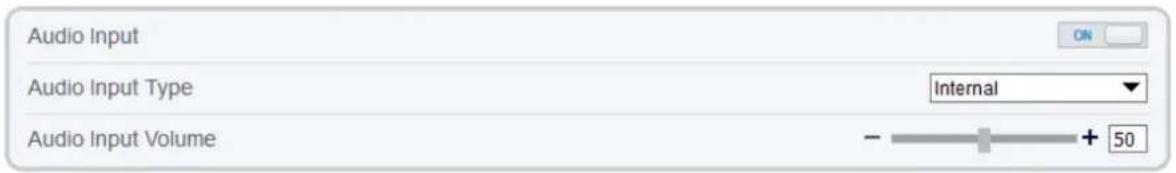
Description
On the Audio Input page, you can set the audio input mode and volume.
Procedure
Step 1 Choose Configuration > Device > Audio Input.
The Audio Input page is displayed, as shown in Figure 4-10. Table 4-10 describes the parameters.
Figure 4-10 Audio Input Page

Audio Input
text_image
Audio Input Audio Input Type Internal Audio Input Volume - + 50
Table 4-10 Audio Input Parameters
| Parameter | Description | Setting |
| Enable Audio Input | Indicates whether to enable the audio input function. | [Setting method]Click the button on to enable audio input. |
| Audio Input Type | Audio input types include: Line In / InternalAn active audio input is required. | [Setting method]Select a value from the drop-down list box. |
| Audio Input Volume | Allows you to adjust the audio input volume. | [Setting method]Slide the slider left or right.[Default value]50NOTEThe value ranges from 0 to 100. |
Step 2 Click Apply.
The message "Apply success!" is displayed. And the system saves the settings.
---End
4.11 Audio Output (Only for Some Models)
Description
On the Audio Output page, you can set the audio input mode and volume.
Procedure
Step 1 Choose Configuration > Device > Audio Output.
The Audio Output page is displayed, as shown in Figure 4-11. Table 4-11 describes the parameters.
Figure 4-11 Audio Output Page

Audio Output

text_image
Audio Output Audio Output Type External Audio Output Volume - + 100

Audio Output
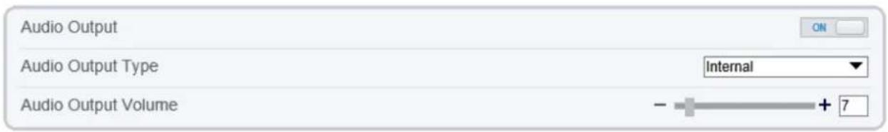
text_image
Audio Output Audio Output Type Internal Audio Output Volume - + 7
Table 4-11 Audio Output Parameters
| Parameter | Description | Setting |
| Enable Audio Output | Indicates whether to enable the audio output function. | [Setting method]Click the button on to enable audio output. |
| Audio Output Type | Microphone types include:ExternalAn active audio output is required.Internal means the camera own speaker. | [Setting method]Select a value from the drop-down list box. |
| Audio output Volume | Allows you to adjust the audio output volume. | [Setting method]Slide the slider left or right.[Default value]50NOTEThe value ranges from 0 to 100. |
Step 2 Click Apply.
The message "Apply success!" is displayed. And the system saves the settings.
---End
4.12 Dome PTZ (Only for Some Models)
Description
The high speed dome cameras are connected to 485 keyboards, users can use the keyboard to control the cameras' PTZ menu.
Procedure
Step 1 Choose Configuration > Device > Dome PTZ.
The Dome PTZ page is displayed, as shown in Figure 4-12.
Figure 4-12 Dome PTZ Page

text_image
Dome PTZ PTZ Address 1 Refresh ApplyStep 2 Input the PTZ address, the default is 1.
Step 3 Click Apply.
The message "Apply success!" is displayed. And the system saves the settings.
----End
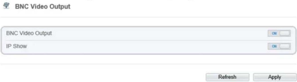
4.13 CVBS Function (Only for Some Models)
Preparation
Connect a display device to the VIDEO OUT port.
Description
When the analog output function is enabled, the IP camera can send analog signals to a video server or display device through the VIDEO OUT port.
Procedure
Step 1 Choose Configuration > Device > CVBS.
The BNC Video Output page is displayed, as shown in Figure 4-13.
Figure 4-13 BNC Video Output Page
text_image
BNC Video Output BNC Video Output IP Show Refresh ApplyStep 2 Click the button on to enable BNC Video Output.
Step 3 Click Apply.
The message "Apply success!" is displayed. And the system saves the settings.
---End
4.14 System Service
Procedure
Step 1 Choose Configuration > Device > System.
The System page is displayed, as shown in Figure 4-14.
Figure 4-14 System Service Page

System

text_image
Language English
text_image
Web Mode HTTP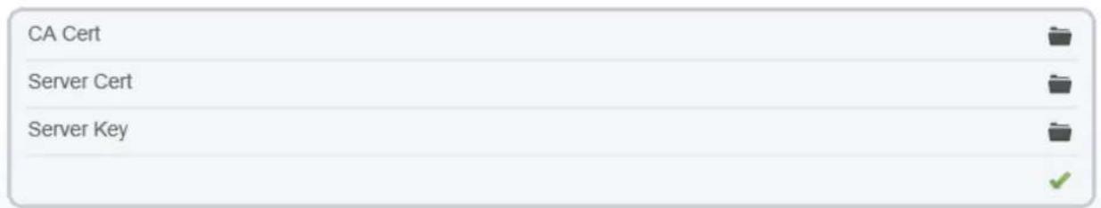
text_image
CA Cert Server Cert Server Key
Step 2 Select an language from the Language drop-down list box.
Step 3 Click, the message "Apply success" is displayed.
Step 4 Click OK, the system saves the settings.
Step 5 Select a Web Mode from the Web Mode drop-down list box.
Step 6 Click , the message "This operation will lead to the device to restart, continue?" is displayed.
Step 7 Click OK, the device restarts and saves the settings automatically.
Step 8 Choose the CA cert, server cert, server cert, server key from the local folder,
Step 9 Click to update the certificate.
---End
4.15 Voice Denoise (Only for Some Models)
Description
On the Voice Denoise page, you can enable the Voice Denoise to reduce the effect of external environmental noise on the built-in MIC.
Procedure
Step 1 Choose Configuration > Device > Voice Denoise
The Voice Denoise page is displayed, as shown in Figure 4-15.
Figure 4-15 Voice Denoise Page

text_image
Voice Denoise Voice Denoise OFF Refresh ApplyStep 2 Click the Voice Denoise button to enable the Voice Denoise.
Step 3 Click Apply.
The message "Apply success" is displayed, the system saves the setting.
---End
4.16 Software Licenses
Procedure
Step 1 Click Configuration > Device > Software Licenses.
The Software Licenses page is displayed, as shown in Figure 4-16.
Figure 4-16 Software Licenses Page

text_image
Software Licenses Open Source Software Licenses View LicensesStep 2 Click View Licenses, you can view the open source software licenses.
---End
5 Configure External Devices
5.1 External PTZ Parameters (Only for Some Models)
Description
When the IP camera is connected to an external PTZ, you can set external PTZ parameters, such as PTZ Protocol, PTZ Address, Baud Rate, and Data Bits.

CAUTION
This function is available only for a camera connected to an external PTZ. The PTZ address must be set to the address of the external PTZ; otherwise, the external PTZ cannot be used.
Procedure
Step 1 Choose Configuration > External Device > PTZ.
The PTZ page is displayed, as shown in Figure 5-1.
Figure 5-1 PTZ Page

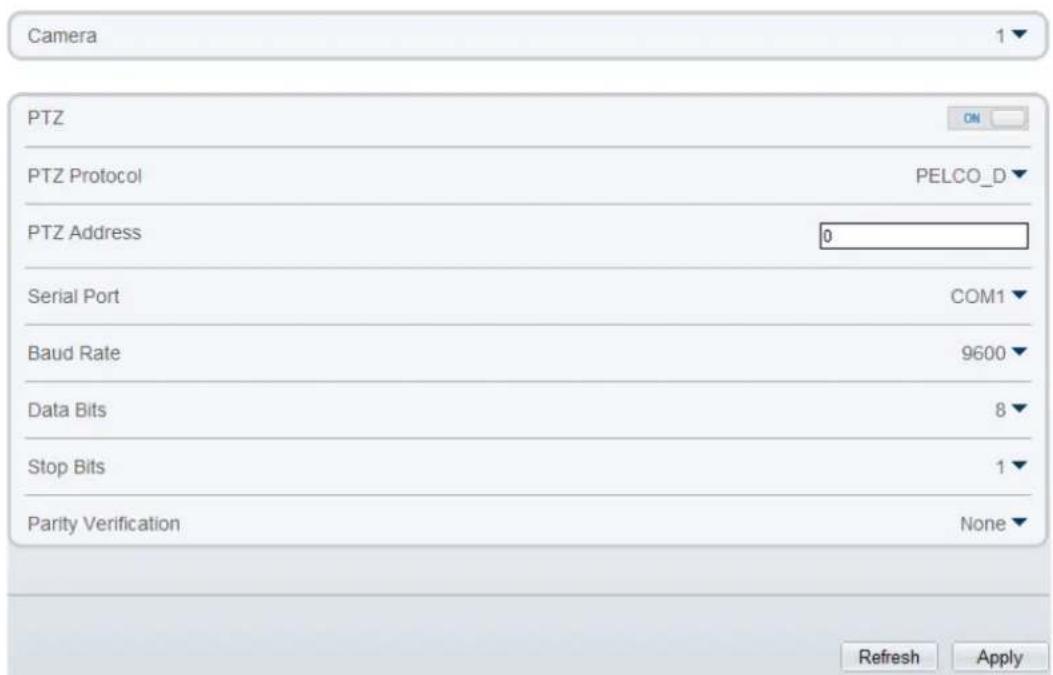
text_image
Camera PTZ PTZ Protocol PELCO_D▼ PTZ Address 0 Serial Port COM1▼ Baud Rate 9600▼ Data Bits 8▼ Stop Bits 1▼ Parity Verification None▼ Refresh ApplyStep 2 Set the parameters according to Table 5-1.
Table 5-1 PTZParameters
| Parameter | Description | Setting |
| PTZ | Enable this function if the device connects to an external PTZ.NOTEThis check box is dimmed for an IP dome camera. | [Setting method]Click the button on to enable PTZ configuration. |
| PTZ Protocol | Protocol used by the external PTZ, such as PELCO_D and PELCO_P. | [Setting method]Select a value from the drop-down list box.NOTEWhen external PTZ parameters are configured, these parameters must match the settings on the external PTZ. |
| PTZ Address | Address of the external PTZ. | |
| Serial Port | The default value is COM1. | |
| Baud Rate | Baud rate used by the external PTZ. The value ranges from 300 bit/s to 115200 bit/s. The default value is 4800 bit/s. | |
| Data Bits | The value must match the setting used by the external PTZ. It can be set to a value ranging from 4 to 8. Generally, the value is 8. | |
| Stop Bits | N/A | |
| Parity Verification | N/A |
Step 3 Click Apply.
The message "Apply success!" is displayed, and the system saves the settings.
---End
6 Advanced Intelligent Analysis
6.1 Smoke and Flame Detection
Description
The smoke flame detection function refers to that an alarm is generated when something is smoking or generating flame at the deployment area.
Procedure
Step 1 Select Configuration > Advanced Intelligent Analysis > Smoke and Flame Detection to access the Smoke and Flame Detection interface, as shown in Figure 6-1.
Figure 6-1 Smoke and flame detection interface

Smoke and Flame Detection
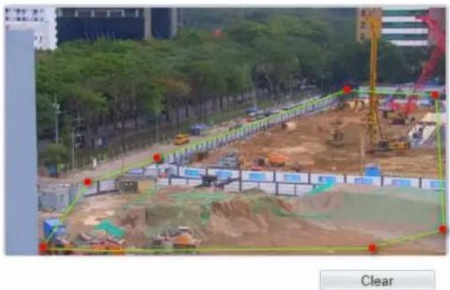
natural_image
Construction site with excavators and earthworks, surrounded by trees and buildings (no visible text or symbols)
text_image
Mode Normal Mode Enable OFF Output Channel 12 Audible Alarm OFF Sensitivity 5 Alarm Record OFF SMTP OFF FTP Upload OFF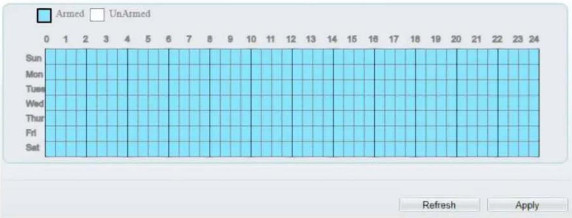
bar
| Day | Armed | UnArmed | |---|---|---| | Sun | 1 | 0 | | Mon | 1 | 0 | | Tues | 1 | 0 | | Wed | 1 | 0 | | Thur | 1 | 0 | | Fri | 1 | 0 | | Sat | 1 | 0 | Refresh Apply
Smoke and Flame Detection
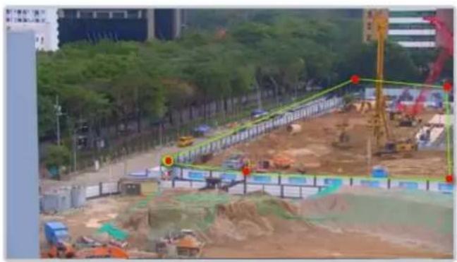
natural_image
Construction site with excavators and cranes, surrounded by greenery and buildings (no visible text or symbols)
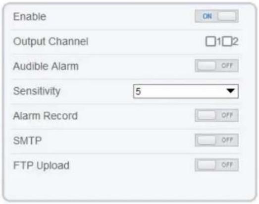
text_image
Enable Output Channel Audible Alarm Sensitivity 5 Alarm Record SMTP FTP Upload
bar
| Day | Armed | UnArmed | |---|---|---| | Sun | 0 | 0 | | Mon | 1 | 0 | | Tue | 0 | 0 | | Wed | 0 | 1 | | Thur | 0 | 0 | | Fri | 0 | 0 | | Sat | 0 | 0 |Step 2 Set all parameters for Intrusion. Table 6-1 describes the specific parameters.
Table 6-1 Smoke flame detection description
| Parameter | Description | Setting |
| Mode (only for PTZ camera) | There are two modes can be chosen, normal mode and preset point mode. | [How to set]Choose from the drop-down list[Default value]Normal mode |
| Preset Point | When you choose the preset point mode, please choose one which is set in advanced. | --- |
| Enable | At thermal channel, Enable the button to enable the alarm. | [How to set]Click Enable to enable.[Default value]OFF |
| Output Channel | If you check to set the Output Channel and the device is connected to an external alarm indicator, the alarm indicator signals when an alarm is triggered. | [How to set]Click to select an ID. |
| Audible Alarm | Enable, when happen the alarm, it will be play audio to alarm.Choose the sound alarm file (set at the “Configuration > Alarm > Audible Alarm Output”). | [How to set]Click to enable Audible alarm [Default value]OFF |
| Sensitivity | The sensitivity of detecting smoker, when the value is high, the alarm can be triggered easily, but the accuracy will be lower. | [How to set]Choose from the drop-down list [Default value]5 |
| Alarm Record | When users install SD card to camera; enable that when happen the alarm, it will be recording the alarm. | [How to set]Click to enable alarm record. [Default value]OFF |
| SMTP | Enable the button to enable SMTP serve. | [How to set]Click to enable SMTP. [Default value]OFF |
| FTP Upload | Enable the button to enable File Transfer Protocol. | [How to set]Click to enable FTP Upload. [Default value]OFF |
Step 3 Set a deployment area. Move the cursor to the drawing interface and click to generate a point, move the cursor to draw a line, and then click to generate another point. This is how a line is generated. In this way, continue to draw lines to form any shape, and right-click to finish line drawing.

NOTE
● A drawn line cannot cross another one, or the line drawing fails.
● Any shape with 32 sides at most can be drawn.
● The quantity of deployment areas is up to 8.
Step 4 Set deployment time.
Click the armed icon ☐ Armed to set the arming time. Click the Unarmed icon ☐ UnArmed to set the unarming time.
Method 1: Click left mouse button to select any time point within 0:00-24:00 from Monday to Sunday.
Method 2: Hold down the left mouse button, drag and release mouse to select the deployment time within 0:00-24:00 from Monday to Sunday.
Deleting deployment time: Click ☐ UnArmed to delete the selected deployment time. The methods are same as set deployment time.

NOTE
- When you select time by dragging the cursor, the cursor cannot be moved out of the time area. Otherwise, no time can be selected.
Figure 6-2 Deployment time setting interface

---End
7 Configure Intelligent Analysis
7.1 Intrusion
Description
The intrusion function refers to that an alarm is generated when target objects (such as person, car, and both person and car) enter the deployment area.
Procedure
Step 1 Select Intelligent Analysis > Intrusion to access the Intrusion interface, as shown in Figure 7-1
Figure 7-1 Intrusion Setting Interface

Intrusion
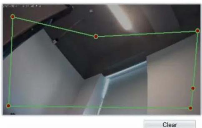
text_image
图层 1-3 - 空心窗 P Clear
text_image
Enable Sensitivity 5 Limit Type OFF Output Channel 1 Audible Alarm OFF Flashlight Alarm OFF Alarm Record OFF SMTP OFF
bar
| Day | Armed | UnArmed | |---|---|---| | Sun | 1 | 0 | | Mon | 2 | 0 | | Tue | 3 | 0 | | Wed | 4 | 0 | | Thur | 5 | 0 | | Fri | 6 | 0 | | Set | 7 | 0 | | 0-1 | 8 | 0 | | 1-2 | 9 | 0 | | 2-3 | 10 | 0 | | 3-4 | 11 | 0 | | 4-5 | 12 | 0 | | 5-6 | 13 | 0 | | 6-7 | 14 | 0 | | 7-8 | 15 | 0 | | 8-9 | 16 | 0 | | 9-10 | 17 | 0 | | 10-11 | 18 | 0 | | 11-12 | 19 | 0 | | 12-13 | 20 | 0 | | 13-14 | 21 | 0 | | 14-15 | 22 | 0 | | 15-16 | 23 | 0 | | 16-17 | 24 | 0 | Refresh Apply
Intrusion
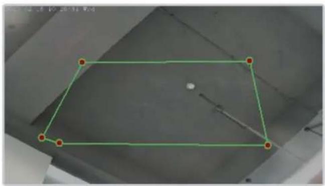
natural_image
Simple geometric diagram of a rectangle inside a ceiling, with no text or symbols present.
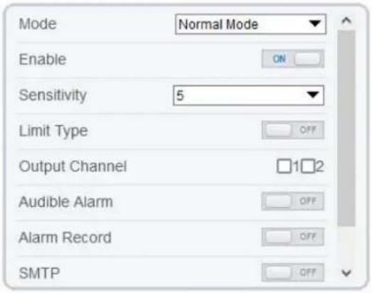
text_image
Mode Normal Mode Enable ON Sensitivity 5 Limit Type OFF Output Channel 12 Audible Alarm OFF Alarm Record OFF SMTP
bar
| Day | Armed | UnArmed | |---|---|---| | Sun | 1 | 0 | | Mon | 1 | 0 | | Tues | 1 | 0 | | Wed | 1 | 0 | | Thur | 1 | 0 | | Fri | 1 | 0 | | Sat | 1 | 0 |
Step 2 Set all parameters of intrusion. Table 7-1 describes the specific parameters.
Table 7-1 IntrusionParameter Description
| Parameter | Description | Setting |
| Mode (only for PTZ camera) | There are two modes can be chosen, normal mode and preset point mode.When you choose the preset point mode, please choose one which is set in advanced. | [How to set]Choose from the drop-down list[Default value]Normal mode |
| Enable | Enable the button to enable the alarm. | [How to set]Click the button on.[Default value]OFF |
| Sensitivity | The sensitivity of detecting the target, when the value is high, the target can be detected easily, but the accuracy will be lower. | [How to set]Choose from the drop-down list[Default value]5 |
| Limit Type | Enable to choose the limit type (person or car / person / car) from type drop-down list. | [How to set]Click the button on.[Default value]OFF |
| Output Channel | If you check to set the Output Channel and the device is connected to an external alarm indicator, the alarm indicator signals when an alarm is triggered. Only for Some Models. | [How to set]Click to select an ID. |
| Audible alarm | Enable, when the alarm happens, it will be play audio to alarm.Choose the audible alarm file (set at the “Configuration > Alarm > Audible Alarm Output”). | [How to set]Click to enable Audio Detection Alarm[Default value]OFF |
| Flashlight Alarm | Enable to flashlight alarm when it triggers the alarm, the flashlight will flash. Only for some models. | [How to set]Click the button on.[Default value]OFF |
| Alarm Record | Enable the button to enable the alarm record. | [How to set]Click to enable Alarm Record.[Default value]OFF |
| SMTP | Enable the button to enable SMTP sever. More details please refer to chapter 13.5 | [How to set]Click to enable SMTP.[Default value]OFF |
| FTP Upload | Enable the button to enable File Transfer Protocol. More details please refer to chapter 13.6 . | [How to set]Click to enable FTP Upload.[Default value]OFF |
| Whitelight Alarm | When the DayNight mode is chosen Night mode, and the light is IR LED or NONE, this linkage action is valid.Enable to whitelight alarm when it triggers the alarm, the whitelight will be on. Only for Some Models. | [How to set]Click the button on.[Default value]OFF |
Step 3 Set a deployment area
Move the cursor to the drawing interface and click to generate a point, move the cursor to draw a line, and then click to generate another point. This is how a line is generated. In this way, continue to draw lines to form any shape, and right-click to finish line drawing, as shown in Figure 7-2.
Figure 7-2 Deployment Area Setting Interface
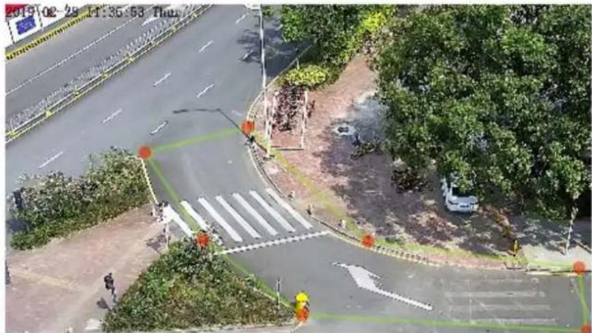
text_image
2019/02-28 11:36:53 Thu
NOTE
A drawn line cannot cross another one, or the line drawing fails.
Any shape with 8 sides at most can be drawn.
The quantity of deployment areas is up to 8.
Step 4 Set deployment time
Click the armed icon □ Armed to set the arming time. Click the Unarmed icon □ UnArmed to set the unarming time.
Method 1: Click left mouse button to select any time point within 0:00-24:00 from Monday to Sunday.
Method 2: Hold down the left mouse button, drag and release mouse to select the deployment time within 0:00-24:00 from Monday to Sunday.
Deleting deployment time: Click ☐ UnArmed to delete the selected deployment time. The methods are same as set deployment time.

NOTE
When you select time by dragging the cursor, the cursor cannot be moved out of the time area. Otherwise, no time can be selected.
Figure 7-3 Deployment Time Setting Interface

bar
| Day | Armed | UnArmed | |---|---|---| | Sun | 1 | 0 | | Mon | 2 | 0 | | Tues | 3 | 0 | | Wed | 4 | 0 | | Thur | 5 | 0 | | Fri | 6 | 0 | | Sat | 7 | 0 | | Sun | 8 | 0 | | Mon | 9 | 0 | | Tues | 10 | 0 | | Wed | 11 | 0 | | Thur | 12 | 0 | | Fri | 13 | 0 | | Sat | 14 | 0 | | Sun | 15 | 0 | | Mon | 16 | 0 | | Tues | 17 | 0 | | Wed | 18 | 0 | | Thur | 19 | 0 | | Fri | 20 | 0 | | Sat | 21 | 0 | | Sun | 22 | 0 | | Mon | 23 | 0 | | Tues | 24 | 0 | | Wed | 25 | 0 | | Thur | 26 | 0 | | Fri | 27 | 0 | | Sat | 28 | 0 |---End
7.2 Single Line Crossing
Description
A single line crossing is a line that is set at a concerned position within the monitored field of view and specifies the forbidden travel direction, an alarm is generated when target objects (such as person or car) cross this line.
Procedure
Step 1 Select Intelligent Analysis > Single Line Crossing to access the Single Line Crossing setting interface, as shown in Figure 7-4.
Figure 7-4 Single Line Crossing Setting Interface

Single Line Crossing

text_image
Reverse Clear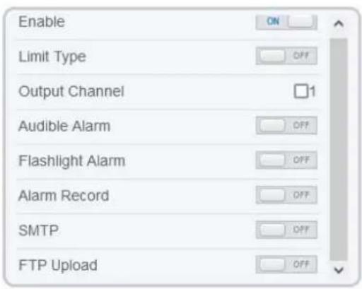
text_image
Enable Limit Type Output Channel Audible Alarm Flashlight Alarm Alarm Record SMTP FTP Upload

Single Line Crossing

natural_image
Interior view of a clean, dark surface with no visible text or symbolsBidirectic

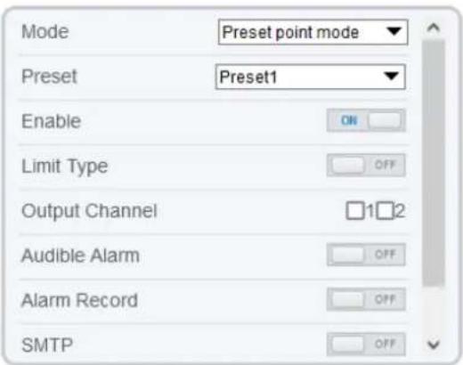
text_image
Mode Preset point mode Preset Preset1 Enable ON Limit Type OFF Output Channel 12 Audible Alarm OFF Alarm Record OFF SMTP
bar
| Day | Armed | UnArmed | |---|---|---| | Sun | 1 | 0 | | Mon | 1 | 0 | | Tues | 1 | 0 | | Wed | 1 | 0 | | Thur | 1 | 0 | | Fri | 1 | 0 | | Sat | 1 | 0 |Refresh

Step 2 Set all parameters of the single line crossing. Table 7-2 describes the specific parameters.
Table 7-2 Parameters of Single Line Crossing
| Parameter | Description | Setting |
| Mode (only for PTZ camera) | There are two modes can be chosen, normal mode and preset point mode.When you choose the preset point mode, please choose one which is set in advanced. | [How to set]Choose from the drop-down list[Default value]Normal mode |
| Enable | Enable the button to enable the alarm. | [How to set]Click the button on . [Default value]OFF |
| Sensitivity | The sensitivity of detecting the target, when the value is high, the target can be detected easily, but the accuracy will be lower. | [How to set]Choose from the drop-down list[Default value]5 |
| Limit Type | Enable to choose the limit type (person or car / person / car) from type drop-down list. | [How to set]Click the button on.[Default value]OFF |
| Output Channel | If you check to set the Output Channel and the device is connected to an external alarm indicator, the alarm indicator signals when an alarm is triggered. Only for some models. | [How to set]Click to select an ID. |
| Audible Alarm | Enable, when the alarm happens, it will be play audio to alarm.Choose the audible alarm file (set at the “Configuration > Alarm > Audible Alarm Output”).Only for some models. | [How to set]Click the button on.[Default value]OFF |
| Flashlight Alarm | Enable to flashlight alarm when it triggers the alarm, the flashlight will flash. Only for some models. | [How to set]Click the button on.[Default value]OFF |
| Alarm Record | Enable the button to enable the alarm record. | [How to set]Click to enable Alarm Record.[Default value]OFF |
| SMTP | Enable the button to enable SMTP sever.Details please refer to chapter 10.5. | [How to set]Click to enable SMTP.[Default value]OFF |
| FTP Upload | Enable the button to enable File TransferProtocol. Details please refer to chapter 10.6. | [How to set]Click to enable FIP.[Default value]OFF |
| Whitelight Alarm | When the DayNight mode is chosen Night mode, and the light is IR LED or NONE, this linkage action is valid.Enable to whitelight alarm when it triggers the alarm, the whitelight will be on. Only for Some Models. | [How to set]Click the button on.[Default value]OFF |
Step 3
Set a deployment area
Drawing a line: Move the cursor to the drawing interface, hold down the left mouse button, and move the cursor to draw a line. When you release the left mouse button, a single line crossing is generated.
Setting a single line crossing: Click a line (and the trip line turns red) to select the single line crossing and set its direction as positive, reverse or bidirectional, or delete the selected line. You can also press and hold left mouse button at the endpoint of a single line crossing and move the mouse to modify the position and length of this single line crossing. You can right-click to delete the single line crossing, as shown in Figure 7-5.
Figure 7-5 Deployment Area Setting Interface
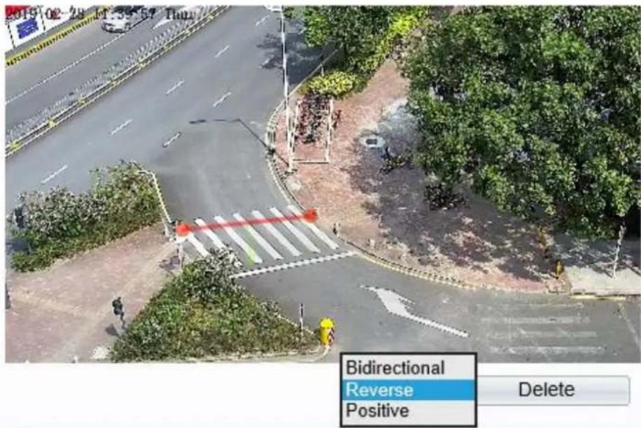
text_image
2019-02-28 15:34:57 Thu Bidirectional Reverse Positive Delete
NOTE
Try to draw the single line crossing in the middle, because the recognition of a target takes time after target appearance on the screen and an alarm is generated only when the object is recognized to have crossed the single line crossing.
The single line crossing which detects person foot as the recognition target cannot be too short, because a short single line crossing tends to miss targets.
Step 4
Set deployment time.
For more details, please refer to 7.1 Step 4.
---End
7.3 Double Line Crossing
Description
Double virtual fences refer to two lines that are set at a concerned special position within the field of view and specify the forbidden travel direction. when target objects (such as person or car) move along the set travel direction and cross these lines in a certain order (line 1 followed by line 2) in pass max time, an alarm is generated.
Procedure
Step 1 Select Intelligent Analysis > Double Line Crossing to access the Double Line Crossing setting interface, as shown in Figure 7-6.
Figure 7-6 Double Line Crossing Setting Interface

Double Line Crossing
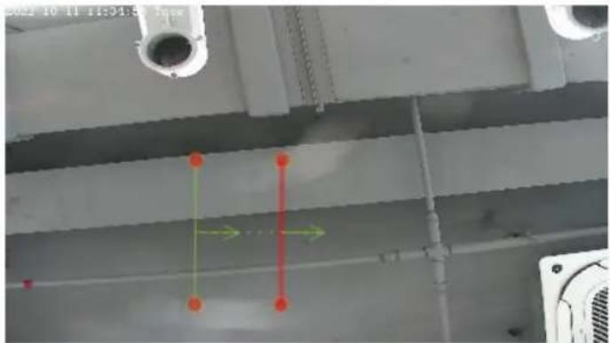
natural_image
Interior view of a ceiling structure with pipes and structural elements, no visible text or symbols

text_image
Enable ON Limit Type OFF Output Channel □1□2 Audible Alarm OFF Alarm Record OFF SMTP OFF FTP Upload OFF
text_image
Sun Mon Tues Wed Thur Fri Sat
Step 2 Set all parameters of the double line crossing. Table 7-3 describes the specific parameters.
Table 7-3 Parameters of Double Virtual Fence
| Parameter | Description | Setting |
| Mode (only for PTZ camera) | There are two modes can be chosen, normal mode and preset point mode.When you choose the preset point mode, please choose one which is set in advanced. | [How to set]Choose from the drop-down list[Default value]Normal mode |
| Enable | Enable the button to enable the alarm. | [How to set]Click to enable.[Default value]OFF |
| Limit Type | Enable to choose the limit type (person or car / person / car) from type drop-down list. | [How to set]Click the button on.[Default value]OFF |
| Output Channel | If you check to set the Output Channel and the device is connected to an external alarm indicator, the alarm indicator signals when an alarm is triggered. Only for some models. | [How to set]Click to select an ID. |
| Audible Alarm | Enable, when the alarm happens, it will be play audio to alarm.Choose the audible alarm file (set at the “Configuration > Alarm > Audible Alarm Output”).Only for some models. | [How to set]Click the button on.[Default value]OFF |
| Flashlight Alarm | Enable to flashlight alarm when it triggers the alarm, the flashlight will flash. Only for some models. | [How to set]Click the button on.[Default value]OFF |
| Alarm Record | Enable the button to enable the alarm record. | [How to set]Click to enable Alarm Record.[Default value]OFF |
| SMTP | Enable the button to enable SMTP sever. For more details, please refer to chapter 13.5 | [How to set]Click to enable SMTP.[Default value]OFF |
| FTP Upload | Enable the button to enable File Transfer Protocol. For more details, please refer to chapter 13.6 . | [How to set]Click to enable FTP.[Default value]OFF |
| Whitelight Alarm | When the DayNight mode is chosen Night mode, and the light is IR LED or NONE, this linkage action is valid.Enable to whitelight alarm when it triggers the alarm, the whitelight will be on. Only for Some Models. | [How to set]Click the button on.[Default value]OFF |
Step 3
Set a deployment area
Drawing a line: Move the cursor to the drawing interface, hold down the left mouse button, and move the cursor to draw two lines. When you release the left mouse button, two numbered virtual fences are generated. Choose either of the double line crossing to set the direction to Positive or Reverse.
Setting double line crossing: Click one of the double line crossing (and the virtual fence turns red) to select this virtual fence and set the direction to Positive or Reverse, or delete the selected line. You can
also press and hold left mouse button at the endpoint of a virtual fence and move the mouse to modify the position and length of this virtual fence. You can right-click to delete the double line crossing, as shown in Figure 7-7.
Figure 7-7 Deployment Area Setting Interface

text_image
2019 02-28 1:45:05 Tha
NOTE
The two virtual fences are in sequential order. An alarm is generated only when a target crosses virtual fence 1 and then virtual fence 2 within the set maximum passing time.
Try to draw double line crossing in the middle, because the recognition of a target takes time after target appearance on the screen and an alarm is generated only when the object is recognized to have crossed the double line crossing.
The double line crossing which detect person foot as the recognition target cannot be too short, because short double line crossing tend to miss targets.
The double line crossing is not supported to modify the direction manually, you can change the direction by choosing Reverse.
Step 4
Set deployment time.
More details please refer to 7.1 Step 4
---End
7.4 Multi-Loitering
Description
Multi-Loitering allows setting the shortest loitering time for multiple targets of specified type (such as person or car) within the deployment area in the field of view. When the loitering time of the multiple targets within this area meets the set shortest loitering time, an alarm is generated.
Procedure
Step 1 Select Intelligent Analysis > Multi-Loitering to access the Multi-Loitering setting interface, as shown in Figure 7-8.
Figure 7-8 Multi-Loitering Setting Interface

Multi-Loitering

text_image
002910 71 11:57:56 3:4 Clear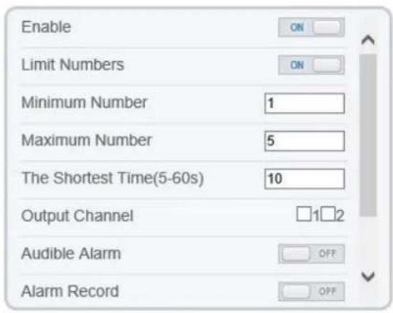
text_image
Enable Limit Numbers Minimum Number 1 Maximum Number 5 The Shortest Time(5-60s) 10 Output Channel □1□2 Audible Alarm OFF Alarm Record OFF
bar
| Day | Value | |---|---| | Sun | 0 | | Mon | 1 | | Tues | 2 | | Wed | 3 | | Thur | 4 | | Fri | 5 | | Sat | 6 | | Sun | 7 | | Mon | 8 | | Tues | 9 | | Wed | 10 | | Thur | 11 | | Fri | 12 | | Sat | 13 | | Sun | 14 | | Mon | 15 | | Tues | 16 | | Wed | 17 | | Thur | 18 | | Fri | 19 | | Sat | 20 | | Sun | 21 | | Mon | 22 | | Tues | 23 | | Wed | 24 | Refresh ApplyStep 2 Set all parameters of multi-loitering. Table 7-4 describes the specific parameters.
Table 7-4 Multi-Loitering Parameter Description
| Parameter | Description | Setting |
| Mode (only for PTZ camera) | There are two modes can be chosen, normal mode and preset point mode.When you choose the preset point mode, please choose one which is set in advanced. | [How to set]Choose from the drop-down list[Default value]Normal mode |
| Enable | Enable the button to enable the alarm. | [How to set]Click the button on.[Default value]OFF |
| Limit Numbers | When Limit Numbers is set to OFF, an alarm is generated no matter how many people loiter. When Limit Numbers is set to ON, if the minimum number is set to 2 alarm is generated for more than 2 people loitering. | [How to set]Click to enable Limit Numbers. |
| The Shortest Time (Sec) | The time that a target object spends in loitering cannot be less than the shortest loitering time. Setting range: 5-60 seconds. | [How to set]Input a value in the area box.[Default value]10 s |
| Output Channel | If you check to set the Output Channel and the device is connected to an external alarm indicator, the alarm indicator signals when an alarm is triggered. Only for some models | [How to set]Click to select an ID. |
| Audible Alarm | Enable, when the alarm happens, it will be play audio to alarm.Choose the audible alarm file (set at the “Configuration > Alarm > Audible Alarm Output”).Only for some models. | [How to set]Click the button on.[Default value]OFF |
| Flashlight Alarm | Enable to flashlight alarm when it triggers the alarm, the flashlight will flash. Only for some models. | [How to set]Click the button on.[Default value]OFF |
| Alarm Record | Enable the button to enable the alarm record. | [How to set]Click to enable Alarm Record.[Default value]OFF |
| SMTP | Enable the button to enable SMTP sever. For more details, please refer to chapter 13.5 | [How to set]Click to enable SMTP.[Default value]OFF |
| FTP Upload | Enable the button to enable File Transfer Protocol. For more details please refer to chapter 13.6 | [How to set]Click to enable FTP Upload.[Default value]OFF |
| Whitelight Alarm | When the DayNight mode is chosen Night mode, and the light is IR LED or NONE, this linkage action is valid.Enable to whitelight alarm when it triggers the alarm, the whitelight will be on. Only for Some Models. | [How to set]Click the button on.[Default value]OFF |
Step 3
Set a deployment area
Move the cursor to the drawing interface and click to generate a point, move the cursor to draw a line, and then click to generate another point. This is how a line is generated. In this way, continue to draw lines to form any shape, and right-click to finish line drawing, as shown in Figure 7-9.
Figure 7-9 Deployment Area Setting Interface

natural_image
Aerial view of a multi-lane road intersection with trees and a pedestrian crossing, no visible text or symbols.
NOTE
A drawn line cannot cross another one, or the line drawing fails.
Any shape with 8 sides at most can be drawn.
The quantity of deployment areas is up to 8.
Step 4
Set deployment time
For more details please refer to 7.1 Step 4.
----End
7.5 Retrograde
Description
Retrograde allows setting the travel direction criteria for a target within an area on the video screen. When a target of specified type (such as people or car) within this area moves in the set travel direction, an alarm is generated.
Procedure
Step 1 Select Intelligent Analysis > Retrograde to access the Retrograde setting interface, as shown in Figure 7-10.
Figure 7-10 Retrograde Setting Interface

Retrograde
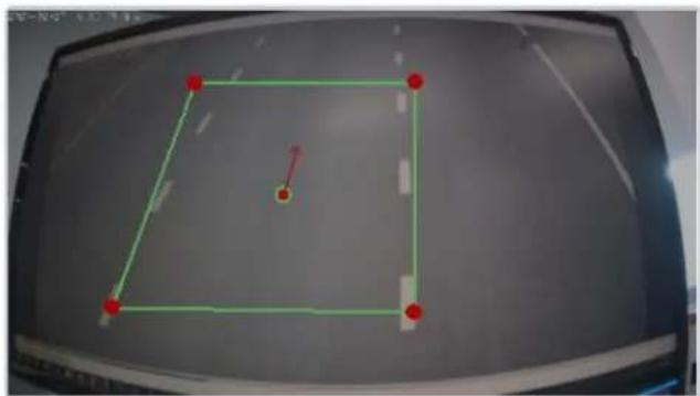
natural_image
Diagram of a soccer field with a green square and red markers, no text or symbols presentClear

text_image
Enable Output Channel Sound Detection Flashlight Alarm Alarm Record SMTP FTP Upload
bar
| Day | Armed | UnArmed | |---|---|---| | Sun | 0 | 0 | | Mon | 1 | 0 | | Tue | 2 | 0 | | Wed | 3 | 0 | | Thur | 4 | 0 | | Fri | 5 | 0 | | Sat | 6 | 0 | | Sun | 7 | 0 | | Mon | 8 | 0 | | Tue | 9 | 0 | | Wed | 10 | 0 | | Thur | 11 | 0 | | Fri | 12 | 0 | | Sat | 13 | 0 | | Sun | 14 | 0 | | Mon | 15 | 0 | | Tue | 16 | 0 | | Wed | 17 | 0 | | Thur | 18 | 0 | | Fri | 19 | 0 | | Sat | 20 | 0 | | Sun | 21 | 0 | | Mon | 22 | 0 | | Tue | 23 | 0 | | Wed | 24 | 0 | | Thur | 23 | 0 | | Fri | 22 | 0 | | Sat | 21 | 0 |Refresh Apply
Step 2 Set all parameters of Retrograde. Table 7-5 describes the specific parameters.
Table 7-5 RetrogradeParameter Description
| Parameter | Description | Setting |
| Mode (only for PTZ camera) | There are two modes can be chosen, normal mode and preset point mode.When you choose the preset point mode, please choose one which is set in advanced. | [How to set]Choose from the drop-down list[Default value]Normal mode |
| Enable | Enable the button to enable the alarm. | [How to set]Click the button on.[Default value]OFF |
| Output Channel | If you check to set the Output Channel and the device is connected to an external alarm indicator, the alarm indicator signals when an alarm is triggered. Only for Some Models. | [How to set]Click to select an ID. |
| Audible Alarm | Enable, when the alarm happens, it will be play audio to alarm.Choose the audible alarm file (set at the “Configuration > Alarm > Audible Alarm Output”).Only for some models. | [How to set]Click the button on.[Default value]OFF |
| Flashlight Alarm | Enable to flashlight alarm when it triggers the alarm, the flashlight will flash. Only for Some Models. | [How to set]Click the button on.[Default value]OFF |
| Alarm Record | Enable the button to enable the alarm record. | [How to set]Click to enable Alarm Record.[Default value]OFF |
| SMTP | Enable the button to enable SMTP sever. More details, please refer to chapter 13.5 | [How to set]Click to enable SMTP.[Default value]OFF |
| FTP Upload | Enable the button to enable File Transfer Protocol.For more details, please refer to chapter 13.6 | [How to set]Click to enable FTP Upload.[Default value]OFF |
| Whitelight Alarm | When the DayNight mode is chosen Night mode, and the light is IR LED or NONE, this linkage action is valid.Enable to whitelight alarm when it triggers the alarm, the whitelight will be on. Only for Some Models. | [How to set]Click the button on.[Default value]OFF |
Step 3
Set a deployment area
Move the cursor to the drawing interface and click to generate a point, move the cursor to draw a line, and then click to generate another point. This is how a line is generated. In this way, continue to draw lines to form any shape, and right-click to finish line drawing, move the arrow in the field can set the direction of converse. as shown in Figure 7-11.
Figure 7-11 Deployment Area Setting Interface

text_image
2019-02-26 13:53:40:17thClear

NOTE
A drawn line cannot cross another one, or the line drawing fails.
Any shape with 8 sides at most can be drawn.
The quantity of deployment areas is up to 8.
Step 4
Set deployment time
For more details, please refer to 7.1 Step 4.
---End
7.6 Illegal Parking (Only for Some Models)
Description
Illegal parking allows setting the dwelling time criteria for a target within the deployment area on the video screen. When the dwelling time of a target of specified type (car) within this area meets the set allowed parking time, an alarm is generated.
Procedure
Step 1 Select Intelligent Analysis > Illegal Parking to access the Illegal Parking setting interface, as shown in Figure 7-12.
Figure 7-12 Illegal Parking Setting Interface

Illegal Parking

natural_image
Construction site with excavators and cranes, surrounded by trees and urban buildings (no visible text or symbols)
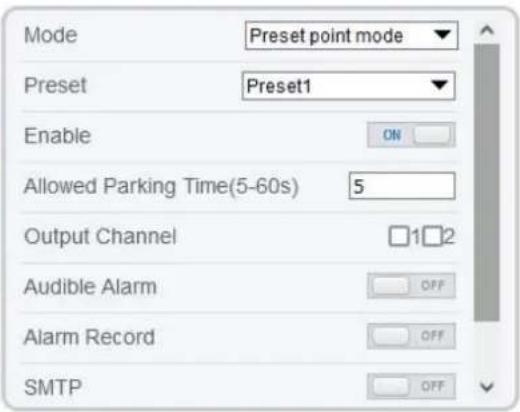
text_image
Mode Preset point mode Preset Preset1 Enable ON Allowed Parking Time(5-60s) 5 Output Channel □1□2 Audible Alarm OFF Alarm Record OFF SMTP
bar
| Day | Armed | UnArmed | |---|---|---| | Sun | 1 | 0 | | Mon | 1 | 0 | | Tue | 1 | 0 | | Wed | 1 | 0 | | Thur | 1 | 0 | | Fri | 1 | 0 | | Sat | 1 | 0 |
Step 2 Set all parameters for illegal parking. Figure 7-13 describes the specific parameters.
Figure 7-13 Description of Parameters for Illegal Parking
| Parameter | Description | Setting |
| Mode (only for PTZ camera) | There are two modes can be chosen, normal mode and preset point mode.When you choose the preset point mode, please choose one which is set in advanced. | [How to set]Choose from the drop-down list[Default value]Normal mode |
| Enable | Enable the button to enable the alarm. | [How to set]Click Enable to enable.[Default value]OFF |
| Allowed Parking Time (Sec) | An alarm is generated when the object left time is longer than the shortest dwelling time. Setting range: 5-60 seconds. | [How to set]Input a value in the area box.[Default value]5 |
| Output Channel | If you check to set the Output Channel and the device is connected to an external alarm indicator, the alarm indicator signals when an alarm is triggered. | [How to set]Click to select an ID |
| Audio Detect Alarm | Enable to choose the sound alarm file from type drop-down list. When it alarms the device will play alarm sound file. Supplied for some models. | [How to set]Click Enable to enable.[Default value]OFF |
| Alarm Record | Enable the button to enable the alarm record. | [How to set]Click to enable Alarm Record.[Default value]OFF |
| SMTP | Enable the button to enable SMTP sever. Details please refer to chapter 10.5. | [How to set]Click to enable SMTP.[Default value]OFF |
| FTP Upload | Enable the button to enable File Transfer Protocol.Details please refer to chapter 10.6. | [How to set]Click to enable FTP Upload.[Default value]OFF |
| Face Linkage | Enable the button to enable trace linkage, when the relevant behaviors are detected, the camera will trace the car or person until the object is disappear, then the camera come back the original position. Supplied for some models. | [How to set]Click to enable Face Linkage.[Default value]OFF |
| Meo Stream Draw Line | Enable the button, the draw line will show at live video when the stream is stream 2. | [How to set]Click to enable Meo Stream Draw Line.[Default value]OFF |
Step 3 Set a deployment area
Move the cursor to the drawing interface and click to generate a point, move the cursor to draw a line, and then click to generate another point. This is how a line is generated. In this way, continue to draw lines to form any shape, and right-click to finish line drawing, as shown in Figure 7-14
Figure 7-14 Deployment Area Setting Interface
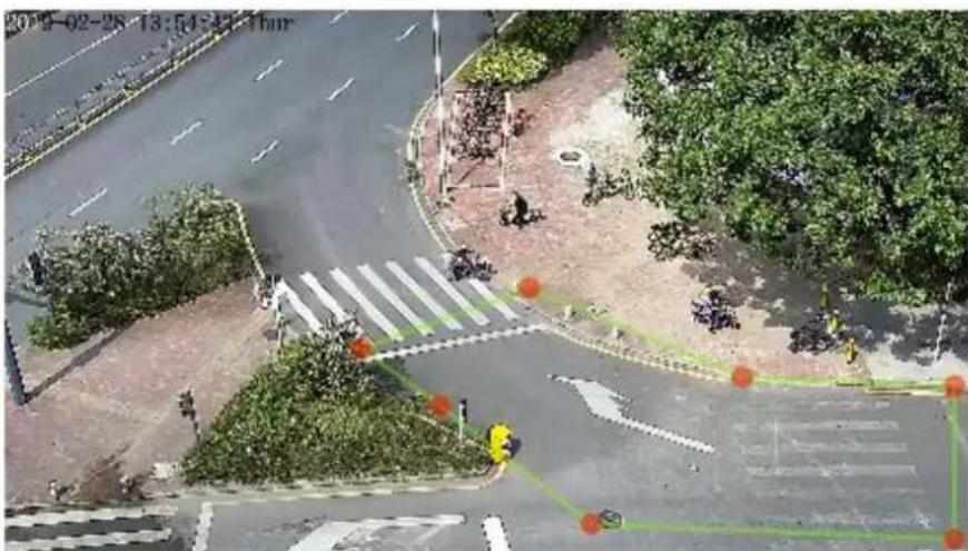
text_image
2019-02-28 13:54:41:17pmClear

NOTE
A drawn line cannot cross another one, or the line drawing fails.
Any shape with 8 sides at most can be drawn.
The quantity of deployment areas is up to 8.
Step 4
Set deployment time.
---End
7.7 People Counting (Only for Some Models)
User can draw line to count the number of people at the special area.
Procedure
Step 1 Select Intelligent Analysis > People Counting to access the People Counting setting interface, as shown in Figure 7-15.
Figure 7-15 People counting

People Counting

natural_image
Interior view of a modern office or lab space with glass doors and a red horizontal line, no visible text or symbols.

text_image
Enable OSD Enable Counting Clear Interval 1Day Clear Counting Area Type Line A->B Out B->A In Set Correction Value OFF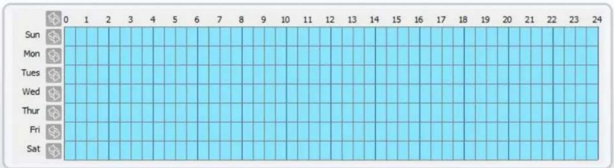
text_image
0 1 2 3 4 5 6 7 8 9 10 11 12 13 14 15 16 17 18 19 20 21 22 23 24 Sun Mon Tues Wed Thur Fri Sat

text_image
Over People Number Alarm OFF Alarm Threshold 1000 Output Channel 1 Audible Alarm OFF Alarm Record OFF SMTP OFF FTP Upload OFF Whitelight Alarm OFFFigure 7-16 People counting for PTZ cameras.

People Counting

text_image
23-02-28 15:03:59 Tues
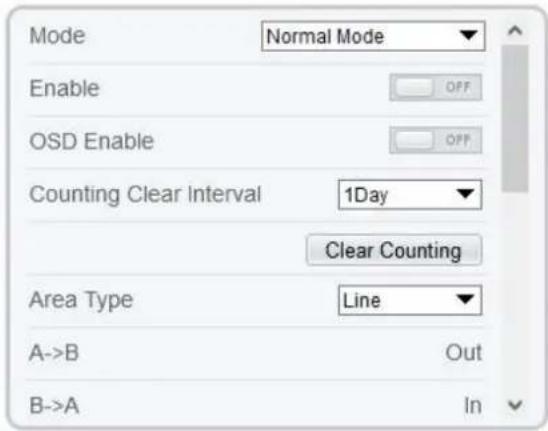
text_image
Mode Normal Mode Enable OFF OSD Enable OFF Counting Clear Interval 1Day Clear Counting Area Type Line A->B Out B->A In
bar
| Day | Armed | UnArmed | |---|---|---| | Sun | 1 | 0 | | Mon | 1 | 0 | | Tues | 1 | 0 | | Wed | 1 | 0 | | Thur | 1 | 0 | | Fri | 1 | 0 | | Sat | 1 | 0 |
Step 2 Set all parameters of illegal parking. Table 7-6 describes the specific parameters.
Table 7-6 Description of Parameters for People Counting
| Parameter | Description | Setting |
| Mode (only for PTZ camera) | There are two modes can be chosen, normal mode and preset point mode. When you choose the preset point mode, please choose one which is set in advanced. | [How to set] Choose from the drop-down list [Default value] Normal mode |
| Enable | Enable the button to enable the alarm. | [How to set] Click the button on. [Default value] OFF |
| OSD Enable | Enable the OSD, the count data will show on live video screen. | [How to set]Click the button on.[Default value]OFF |
| Counting Clear Interval | The camera will clear counting data at the setting interval. 10 min /half- hour /1 hour /2 hours /12 hours /1 day /custom time(hh : mm)Click the “Clear Counting”, clearing the data immediately. | [How to set]Choose from drop-down list.[Default value]12 hours |
| Area Type | Draw a line on live video screen.The label of A and B indicate out and in. | [How to set]Choose from drop-down list.[Default value]Line |
| Set Correction Value | Enable, set the count correction value, it can be positive or negative. For example, if there are 30 people enter the area before counting, input 30 to correct. If 30 people go out the area, input -30. | [How to set]Enable /Input a value in the area box.[Default value]0 |
| Over People Number Alarm | Enable, if the counting number is ovwe the threshold, it will alarm. | [How to set]Click the button on.[Default value]OFF |
| Alarm Threshold | The threshold of activating alarm. | [How to set]Enable /Input a value in the area box.[Default value]1000 |
| Output Channel | If you check to set the Output Channel and the device is connected to an external alarm indicator, the alarm indicator signals when an alarm is triggered. Only for Some Models. | [How to set]Click to select an ID. |
| Flashlight Alarm | Enable to flashlight alarm when it triggers the alarm, the flashlight will flash. Only for Some Models. | [How to set]Click the button on.[Default value]OFF |
| Audible Alarm | Enable, when the alarm happens, it will be play audio to alarm.Choose the audible alarm file (set at the “Configuration > Alarm > Audible Alarm Output”).Only for some models. | [How to set]Click the button on.[Default value]OFF |
| Alarm Record | Enable the button to enable the alarm record. | [How to set]Click to enable Alarm Record.[Default value]OFF |
| SMTP | Enable the button to enable SMTP sever.The parameters of SMTP can be set atConfiguration > Network Service >SMTP interface. | [How to set]Click to enable SMTP.[Default value]OFF |
| FTP Upload | Enable the button to enable File Transfer Protocol.The parameters of FTP can be set atConfiguration > Network Service > FTP interface. | [How to set]Click to enable FTP Upload.[Default value]OFF |
| Whitelight Alarm | When the DayNight mode is chosen Night mode, and the light is IR LED or NONE, this linkage action is valid.Enable to whitelight alarm when it triggers the alarm, the whitelight will be on. Only for Some Models. | [How to set]Click the button on.[Default value]OFF |
Step 3 Set a deployment area
Move the cursor to the drawing interface and click to generate a point, move the cursor to draw a line, and then click to generate another point. This is how a line is generated. In this way, continue to draw lines to form any shape, and right-click to finish line drawing.
Step 4 Set deployment time
For more details please refer to 7.1 Step 4..
---End
7.8 Smart Motion
Description
The smart motion function refers to that an alarm is generated when target objects (such as person, car, and both person and car) move at the deployment area.
Procedure
Step 1 Select Intelligent Analysis > Smart Motion, as shown in Figure 7-17.
Figure 7-17 Smart Motion Setting Interface

Smart Motion
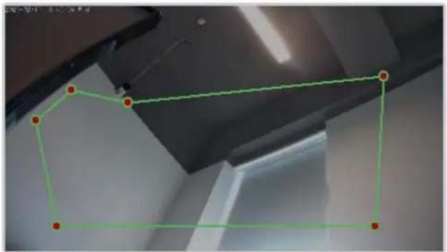
natural_image
Interior ceiling view with a green polygon outline and red dots marking points (no text or symbols)Clear

text_image
Enable Sensitivity 5 Limit Type OFF Output Channel 1 Audible Alarm OFF Flashlight Alarm OFF Alarm Record OFF SMTP OFF
bar
| Day | Armed | UnArmed | |---|---|---| | Sun | 1 | 0 | | Mon | 1 | 0 | | Tues | 1 | 0 | | Wed | 1 | 0 | | Thur | 1 | 0 | | Fri | 1 | 0 | | Sat | 1 | 0 |Refresh Apply

Smart Motion
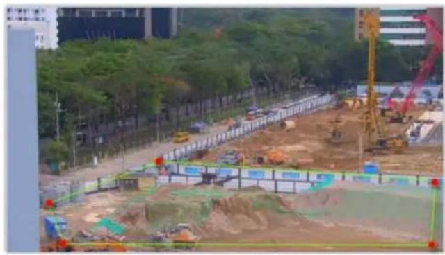
natural_image
Construction site with excavators and cranes, surrounded by trees and urban buildings (no visible text or signage)Clear

text_image
Mode Preset point mode Preset Enable OFF Sensitivity 5 Limit Type OFF Output Channel 12 Audible Alarm OFF Alarm Record OFF
bar
| Day | Armed | UnArmed | |---|---|---| | Sun | 0 | 0 | | Mon | 1 | 0 | | Tue | 2 | 0 | | Wed | 3 | 0 | | Thur | 4 | 0 | | Fri | 5 | 0 | | Sat | 6 | 0 |Refresh Apply
Step 2 Set all parameters of smart motion. Table 7-7 describes the specific parameters.
Table 7-7 Smart Motion Parameter Description
| Parameter | Description | Setting |
| Mode (only for PTZ camera) | There are two modes can be chosen, normal mode and preset point mode.When you choose the preset point mode, please choose one which is set in advanced. | [How to set]Choose from the drop-down list[Default value]Normal mode |
| Enable | Enable the button to enable the alarm. | [How to set]Click the button on.[Default value]OFF |
| Sensitivity | The sensitivity of detecting the target, when the value is high, the target can be detected easily, but the accuracy will be lower. | [How to set]Choose from the drop-down list[Default value]5 |
| Limit Type | Enable to choose the limit type (person or car / person / car) from type drop-down list. | [How to set]Click the button on.[Default value]OFF |
| Output Channel | If you check to set the Output Channel and the device is connected to an external alarm indicator, the alarm indicator signals when an alarm is triggered. Only for Some Models. | [How to set]Click to select an ID. |
| Audible Alarm | Enable, when the alarm happens, it will be play audio to alarm.Choose the audible alarm file (set at the “Configuration > Alarm > Audible Alarm Output”). | [How to set]Click to enable Audio Detection Alarm[Default value]OFF |
| Flashlight Alarm | Enable to flashlight alarm when it triggers the alarm, the flashlight will flash. Only for some models. | [How to set]Click the button on.[Default value]OFF |
| Alarm Record | Enable the button to enable the alarm record. | [How to set]Click to enable Alarm Record.[Default value]OFF |
| SMTP | Enable the button to enable SMTP sever. More details please refer to chapter 13.5 | [How to set]Click to enable SMTP.[Default value]OFF |
| FTP Upload | Enable the button to enable File Transfer Protocol. More details please refer to chapter 13.6 . | [How to set]Click to enable FTP Upload.[Default value]OFF |
| Whitelight Alarm | When the DayNight mode is chosen Night mode, and the light is IR LED or NONE, this linkage action is valid.Enable to whitelight alarm when it triggers the alarm, the whitelight will be on. Only for Some Models. | [How to set]Click the button on.[Default value]OFF |
Step 3 Set a deployment area
Move the cursor to the drawing interface and click to generate a point, move the cursor to draw a line, and then click to generate another point. This is how a line is generated. In this way, continue to draw lines to form any shape, and right-click to finish line drawing.

NOTE
A drawn line cannot cross another one, or the line drawing fails.
Any shape with 8 sides at most can be drawn.
The quantity of deployment areas is up to 8.
Step 4 Set deployment time
Click the armed icon unarming time. to set the arming time. Click the Unarmed icon UnArmed to set the
Method 1: Click left mouse button to select any time point within 0:00-24:00 from Monday to Sunday.
Method 2: Hold down the left mouse button, drag and release mouse to select the deployment time within 0:00-24:00 from Monday to Sunday.
Deleting deployment time: Click ☐ UniArmed to delete the selected deployment time. The methods are same as set deployment time.

NOTE
When you select time by dragging the cursor, the cursor cannot be moved out of the time area. Otherwise, no time can be selected.
Figure 7-18 Deployment Time Setting Interface

---End
8 Configure Intelligent Tracking (Only for Some Models)
8.1 Intelligent Tracking
Description
This function is only used for high speed dome.
Intelligent tracking is able to recognize the basic features such as the position, shape, contour and color of the target with a special algorithm. After comparing and matching with images for each frame, the positions of the target in each frame of the video image are generated, and the motion track of the target is generated. The method performs a real-time monitoring of targets and automatically controls the gimbal to track moving objects. The automatic target tracking function is that the dome camera can continuously track the moving target of the pre-made scene, and automatically adjusts the camera zoom focus according to a moving target distance, and the dome automatically returns to the preset scene when the moving target disappears.
Procedure
Step 5 Select Configuration > Intelligent Tracking to access the Intelligent Tracking setting interface, as shown in Figure 8-1.
Figure 8-1 Intelligent Tracking Interface
Intelligent Tracking
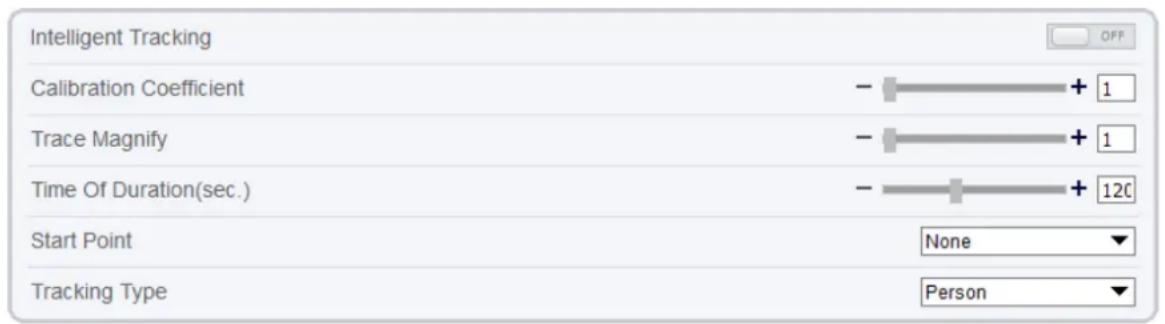
text_image
Intelligent Tracking Calibration Coefficient Trace Magnify Time Of Duration(sec.) Start Point Tracking Type OFF - + 1 - + 1 - + 120 None Person
Step 6 Set all parameters for intelligent tracking. Table 8-1 describes the specific parameters.
Table 8-1 Description of Parameters for Intelligent Tracking
| Parameter | Description | Setting |
| Enable | Click the button on to enable the intelligent tracking | [How to set]Click the button on.[Default value]OFF |
| Calibration Coefficient | It is equivalent to a control coefficient, and real-time tracking doubling rate nonlinear positive correlation; Usually the higher the installation height, the greater the calibration coefficient value; it ranges from 1 to 30. | [Setting method]Drag the slider.[Default value]1 |
| Trace Magnify | It is the value of lens zoom, which has a large influence on the real-time tracking magnification; it ranges from 0 to 30. | [Setting method]Drag the slider.[Default value]7 |
| Time of Duration (sec.) | The maximum time of a tracking period, it ranges from 0 to 300 s. | [Setting method]Drag the slider.[Default value]120 |
| Start Point | Start point of the tracking, you can choose the preset or none. The preset should be set in advanced. | [Setting method]Choose from drop-down list.[Default value]None |
| Type | Choose the tracking type, person or car. | [Setting method]Choose from drop-down list.[Default value]Person |
---End
9 Configure the Alarm Function
Different cameras may have different alarm linkage actions. It depends on the performance of cameras, please refer to actual products.
9.1 Alarm Output (Only for Some Models)
Procedure
Step 1 Choose Configuration > Alarm > Alarm Output.
The Alarm Output page is displayed, as shown in Figure 9-1.
Figure 9-1 Alarm Output Page

Alarm Output

text_image
Alarm Output 1 Name Valid Signal Close Alarm Output Mode Switch Mode Alarm Time(ms)(0:Continuous) 0 Timing Alarm Output OFF Manual control Start Stop Refresh ApplyStep 2 Set the parameters according to Table 9-1.
Table 9-1 Alarm I/O Parameters
| Parameter | Description | Setting |
| Alarm Output | ID of the alarm output channel. NOTE The number of alarm output channels depends on the device model. | [Setting method] Select a value from the drop-down list box. [Default value] 1 |
| Name | Alarm output channel name. | [Value range] 0 to 32 bytes |
| Valid Signal | The options are as follows:Close: An alarm is generated when an external alarm signal is received.Open: An alarm is generated when no external alarm signal is received. | [Setting method]Select a value from the drop-down list box.[Default value]Close |
| Alarm Output Mode | When the device receives I/O alarm signals, the device sends the alarm information to an external alarm device in the mode specified by this parameter. The options include the switch mode and pulse mode.NOTEIf the switch mode is used, the alarm frequency of the device must be the same as that of the external alarm device.If the pulse mode is used, the alarm frequency of the external alarm device can be configured. | [Setting method]Select a value from the drop-down list box.[Default value]Switch Mode |
| Alarm Time (ms) (0: Continuous) | Alarm output duration. The value 0 indicates that the alarm remains valid. | [Setting method]Enter a value manually.[Default value]0[Value range]0 to 86400 seconds |
| Timing Alarm Output | Enable timing alarm output, set the schedule to time alarm.NOTEIf there are two alarm outputs, this setting is only valid for Alarm output 1. | [Setting method]Enable[Default value]OFF |
| Manual Control | Control the alarm output. | N/A |
Step 3 Click Apply.
The message "Apply success!" is displayed, and the system saves the settings.
----End
9.2 Disk Alarm
Procedure
Step 1 Choose Configuration > Alarm > Disk Alarm.
The Disk Alarm page is displayed, as shown in Figure 9-2.
Figure 9-2 Disk Alarm Page

Disk Alarm

text_image
Disk Full Alarm Alarm Interval(10-86400S) 10 Output Channel
Step 2 Click the button on to enable disk alarm.
Step 3 Configure the Alarm Interval parameters.
Step 4 Select Out Channel number (Please refer to the actual product).
Step 5 Click Apply.
The message "Apply success!" is displayed, and the system saves the settings.
---End
9.3 Network Alarm
Procedure
Step 1 Choose Configuration > Alarm > Network Alarm.
The Network Alarm page is displayed, as shown in Figure 9-3.
Figure 9-3 Network Alarm Page

Network Alarm
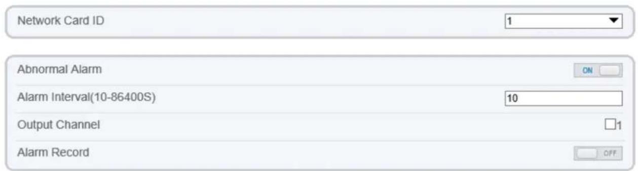
text_image
Network Card ID 1 Abnormal Alarm ON Alarm Interval(10-86400S) 10 Output Channel 1 Alarm Record OFF
Step 2 Click the button on to enable Abnormal alarm.
Step 3 Configure the network alarm interval.
Step 4 Select Output Channel number. You can enable alarm record when you install SD card in advance.
Step 5 Click Apply.
The message "Apply success!" is displayed, the system saves the settings.
---End
9.4 Day Night Switch Alarm
Description
At the setting time, enable the day night switch alarm, when it happens day night switched, it will send alarm signal.
Procedure
Step 1 Choose Configuration > Alarm > Day Night Switch Alarm.
The Day Night Switch Alarm page is displayed, as shown in Figure 9-4.
Figure 9-4 Day Night Switch Alarm

Day Night Switch Alarm
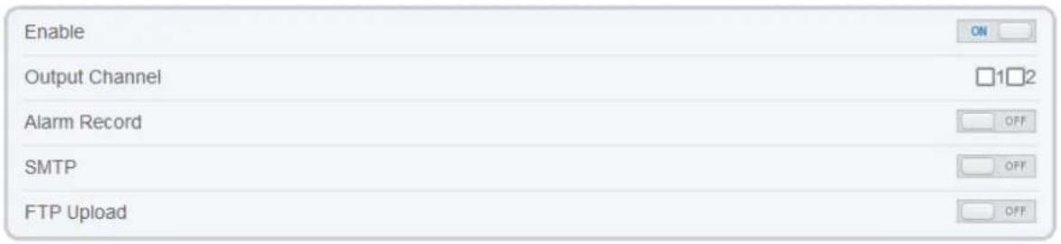
text_image
Enable Output Channel Alarm Record SMTP FTP Upload ON 12 OFF OFF OFF
bar
| Day | Armed | UnArmed | |---|---|---| | Sun | 1 | 0 | | Mon | 1 | 0 | | Tues | 1 | 0 | | Wed | 1 | 0 | | Thur | 1 | 0 | | Fri | 1 | 0 | | Sat | 1 | 0 | Refresh ApplyStep 2 Click the button to enable day night switch alarm.
Step 3 Configure the day night switch alarm schedule.
Click the armed icon ☐ Armed to set the arming time. Click the Unarmed icon ☐ UnArmed to set the unarming time.
Method 1: Click left mouse button to select any time point within 0:00-24:00 from Monday to Sunday.
Method 2: Hold down the left mouse button, drag and release mouse to select the deployment time within 0:00-24:00 from Monday to Sunday.
Deleting deployment time: Click ☐ UnArmed to delete the selected deployment time. The methods are same as set deployment time.

NOTE
When you select time by dragging the cursor, the cursor cannot be moved out of the time area. Otherwise, no time can be selected.
Step 4 Click the button on to enable Alarm Record.
Step 5 Click the button on to enable SMTP.
Step 6 Click the button on to enable FTP Upload.
Step 7 Click Apply.
The message "Apply success!" is displayed, the system saves the settings
---End
9.5 I/O Alarm Linkage (Only for Some Models)
Description
Alarm linkage refers to linkage alarm output. When receiving an alarm from the alarm input port, the camera performs linkage alarm output, and operate based on the linkage policy.
On the I/O Alarm Linkage page, you can perform the following operations:
Enable the I/O alarm function.
Configure the I/O alarm schedule.
Configure the alarm output channel.
Procedure
Step 1 Choose Configuration > Alarm > I/O Alarm Linkage.
The I/O Alarm Linkage page is displayed, as shown in Figure 9-5.
Figure 9-5 I/O Alarm Linkage Page

I/O Alarm Linkage

text_image
Alarm Input 1 Name Trigger Mode Connect Alarm Input OFF Output Channel 12 PTZ Linkage ON PTZ Type Value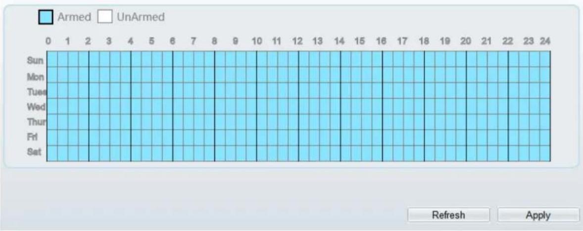
bar
| Day | Armed | UnArmed | |---|---|---| | Sun | 1 | 0 | | Mon | 1 | 0 | | Tues | 1 | 0 | | Wed | 1 | 0 | | Thur | 1 | 0 | | Fri | 1 | 0 | | Sat | 1 | 0 | Refresh ApplyStep 2 Select the Alarm Input value from the drop-down list box.
Step 3 Enter alarm input channel name.
Step 4 Select the Trigger Mode from the drop-down list box.
Step 5 Click the button on to enable I/O Alarm.
Step 6 Configure the I/O alarm schedule.
Click the armed icon □ Armed to set the arming time. Click the Unarmed icon □ UnArmed to set the unarming time.
Method 1: Click left mouse button to select any time point within 0:00-24:00 from Monday to Sunday.
Method 2: Hold down the left mouse button, drag and release mouse to select the deployment time within 0:00-24:00 from Monday to Sunday.
Deleting deployment time: Click ☐ UnArmed to delete the selected deployment time. The methods are same as set deployment time.

NOTE
When you select time by dragging the cursor, the cursor cannot be moved out of the time area. Otherwise, no time can be selected.
Figure 9-6 Schedule Setting Page

Step 7 Select the Out Channel from the drop-down list box.
Step 8 Select the PTZ Type from the drop-down list box. The PTZ type includes preset, scan, track, tour.
Step 9 Select Value. The value is the ID of PTZ type.
Step 10 Click the button on to enable Alarm Record.
Step 11 Click the button on to enable SMTP.
Step 12 Click the button on to enable FTP Upload.
Step 13 Click the button on to enable IR Cut.
Step 14 Click Apply.
The message "Apply succeed!" is displayed, and the system saves the settings.
---End
9.6 Motion Alarm Linkage
Description
On the Motion Alarm page, you can perform the following operations:
Enable the motion detection function.
Set the motion detection alarming time.
Set the motion detection area.
Configure the motion alarm output channel.
When the alarm output function is enabled and the camera detects that an object moves into the motion detection area within the schedule time, the camera generates an alarm and triggers linkage alarm output.
Procedure
Step 1 Choose Configuration >Alarm > Motion Alarm.
The Motion Alarm page is displayed, as shown in Figure 9-7.
Figure 9-7 Motion Alarm Page

Motion Alarm
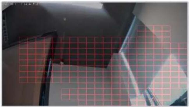
natural_image
Interior view of a room with ceiling and wall, showing a red grid overlay (no text or symbols)

text_image
Enable ON Alarm Interval(1-1800S) 10 Sensitivity 5 Output Channel 1 Audible Alarm OFF Flashlight Alarm OFF Alarm Record OFF SMTP OFF

Step 2 Click the button on to enable motion alarm.
Step 3 Configure the motion alarm interval.
Step 4 Configure the Sensitivity. Tick the output channel when the camera is connected to the external alarm device.
Step 5 Enable Audible Alarm, Flashlight Alarm, Whitelight Alarm. (these linkage actions are only applicable for some models, it depends on the performance of cameras.)
Step 6 Enable Motion Detect Stream, when camera detects the motion, it will show tracking of object.
Step 7 Configure the schedule time setting.
For more details about how to set Schedule, see 9.5 Step 6.
Step 8
Configure the detection area.
- Press and hold the left mouse button, and drag in the video area to draw a detection area, as shown in Figure 9-8.
Figure 9-8 Motion Area Setting Page

Motion Alarm
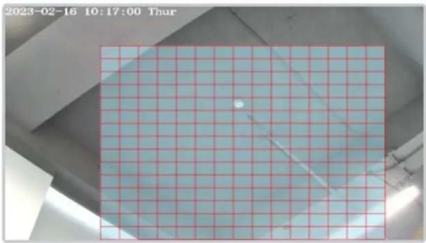
natural_image
Grid-patterned surface with a small bright spot, captured on a building facade (no text or symbols visible)Clear
- Press and hold the left mouse button, and drag in the video area to draw a detection area.

NOTE
Click Clear to delete a detection area. Click the red block to disarm this area.
---End
9.7 Push Message
Description
The alarm notification will be pushed to the mobile app if the devices are managed by app.
Procedure
Step 1 Choose Configuration > Alarm > Push Message.
The Push Message page is displayed, as shown in Figure 9-9.
Figure 9-9 Push Message Page

Push Message
Push Message

The alarm notifications will be pushed to the mobile app if the device is managed by app.
Refresh
Apply
Step 2 Click Apply.
The message "Apply succeed!" is displayed, and the system saves the settings.
---End
9.8 Audible Alarm Output (Only for Some Models)
At Configuration > Alarm > Audible Alarm Output interface, set the audio detect alarm, as shown in Figure 9-10. The volume can be set at Configuration > Device > Audio Output interface, as shown in Figure 4-11.
Figure 9-10 Audible Alarm Output Interface

Audible Alarm Output
| ID | FileName | Cycle Number | Listen Test | Operate |
| 0 | Dangerous area. Keep away.wav | 1 | ↑ | |
| 1 | Deep water. pay attention to safety.wav | 1 | ↑ | |
| 2 | Do not touch valuables.wav | 1 | ↑ | |
| 3 | Hello Welcome.wav | 1 | ↑ | |
| 4 | High altitude. No climbing.wav | 1 | ↑ | |
| 5 | High-temperature ignition point found. Please dispose immediately.wav | 1 | ↑ | |
| 6 | No parking in this area.wav | 1 | ↑ | |
| 7 | Private area. No Entry.wav | 1 | ↑ | |
| 8 | Public area. No smoking.wav | 1 | ↑ | |
| 9 | Smoking is prohibited in this area.wav | 1 | ↑ | |
| 10 | Warning area. Please leave as soon as possible..wav | 1 | ↑ | |
| 11 | You have entered a monitoring area.wav | 1 | ↑ | |
| 12 | You have entered a warning area. Please leave as soon as possible.wav | 1 | ↑ |

bar
| Day | Armed | UnArmed | |---|---|---| | Sun | 1 | 0 | | Mon | 1 | 0 | | Tue | 1 | 0 | | Wed | 1 | 0 | | Thur | 1 | 0 | | Fri | 1 | 0 | | Sat | 1 | 0 |There are 13 default files, users can set the cycle number, click to test listen.
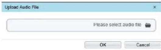
text_image
Upload Audio File Please select audio file OK CancelClick to upload a new audio.
The type should be WAV, size must be less than 250 Kb, the bit rate should be 128 kbps.
Click "Apply" to save the settings.
---End
9.9 Abnormal Sound Detection (Only for Some Models)
Description
The camera has mic or support the line in. On the Audio Abnormal Detection page, you can perform the following operations:
Enable the Audio Abnormal Detection function.
Set the Audio Abnormal Detection alarming time.
Configure the Audio Abnormal Detection output channel.
When the alarm output function is enabled and the camera detects abnormal audio (sudden rise or sudden drop) within the schedule time, the camera generates an alarm and triggers linkage alarm output.
Procedure
Step 1 Choose Configuration >Alarm >Audio Abnormal Detection.
The Audio Abnormal Detection page is displayed, as shown in Figure 9-11.
Figure 9-11 Audio abnormal detection

Abnormal Sound Detection
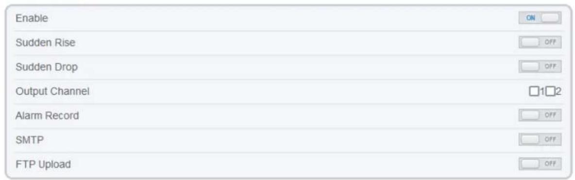
text_image
Enable Sudden Rise Sudden Drop Output Channel Alarm Record SMTP FTP Upload ON OFF OFF 12 OFF OFF OFF
bar
| Day | Armed | UnArmed | |---|---|---| | Sun | 1 | 0 | | Mon | 1 | 0 | | Tues | 1 | 0 | | Wed | 1 | 0 | | Thur | 1 | 0 | | Fri | 1 | 0 | | Sat | 1 | 0 | Refresh ApplyStep 2 Click the button on to enable audio abnormal detection.
Step 3 Enable Sudden Rise, and Sudden Drop.
Step 4 Select the Output Channel.
Step 5 Click the button on to enable Alarm Record.
Step 6 Click the button on to enable SMTP.
Step 7 Click the button on to enable FTP Upload.
Step 8 Configure the schedule time setting.
For details about how to set Schedule, see 9.5 Step 6.
---End
9.10 Flashlight Alarm Output (Only for Some Models)
At Configuration > Alarm > Flashlight Alarm Output interface, set the schedule to enable flashlight alarm, as shown in Figure 9-12.
Figure 9-12 Flashlight alarm interface

Flashlight Alarm Output

text_image
Alarm Time(10-60s) 30 Flicker Interval(100-10000MS) 1000
bar
| Day | Armed | UnArmed | |---|---|---| | Sun | 1 | 0 | | Mon | 1 | 0 | | Tues | 1 | 0 | | Wed | 1 | 0 | | Thur | 1 | 0 | | Fri | 1 | 0 | | Sat | 1 | 0 |
Set the alarm time and flicker interval.
Configure the schedule time setting.
Click "Apply" to save the settings.
---End
9.11 Whitelight Alarm Output (Only for Some Models)
The DayNight mode is chosen Night mode, and the light is IR LED or NONE, Which is the Prerequisite, so that this linkage action is valid.
Enable to whitelight alarm when it triggers the alarm, the whitelight will be on.
At Configuration > Alarm > Whitelight Alarm Output interface, set the duration of alarm, as shown in Figure 9-13.
Figure 9-13 Whitelight alarm interface

Whitelight Alarm Output
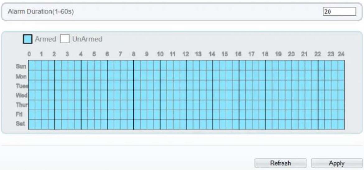
bar
Alarm Duration(1-60s) | Day | Armed | UnArmed | |---|---|---| | Sun | 1 | 0 | | Mon | 2 | 0 | | Tues | 4 | 0 | | Wed | 5 | 0 | | Thur | 6 | 0 | | Fri | 7 | 0 | | Sat | 8 | 0 | | 0 | 9 | 0 | | 1 | 10 | 0 | | 2 | 11 | 0 | | 3 | 12 | 0 | | 4 | 13 | 0 | | 5 | 14 | 0 | | 6 | 15 | 0 | | 7 | 16 | 0 | | 8 | 17 | 0 | | 9 | 18 | 0 | | 10 | 19 | 0 | | 11 | 20 | 0 | | 12 | 21 | 0 | | 13 | 22 | 0 | | 14 | 23 | 0 | | 15 | 24 | 0 | Refresh ApplySet the alarm duration, it determines the duration of the whitelight on.
Configure the schedule time setting.
Click "Apply" to save the settings.
---End
10 AI Multiobject
10.1 AI Configuration
Choose Configuration > AI Multiobject to set parameter of detected face, and vehicle plate.
Figure 10-1 AI Multiobject interface

AI Multiobject
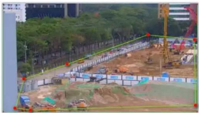
natural_image
Construction site with cranes and excavated earth, surrounded by trees and urban buildings (no visible text or symbols)Clear
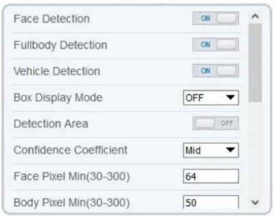
text_image
Face Detection ON Fullbody Detection ON Vehicle Detection ON Box Display Mode OFF Detection Area OFF Confidence Coefficient Mid Face Pixel Min(30-300) 64 Body Pixel Min(30-300) 50
bar
| Day | Armed | UnArmed | |---|---|---| | Sun | 1 | 0 | | Mon | 1 | 0 | | Tues | 1 | 0 | | Wed | 1 | 0 | | Thur | 1 | 0 | | Fri | 1 | 0 | | Sat | 1 | 0 |Refresh Apply
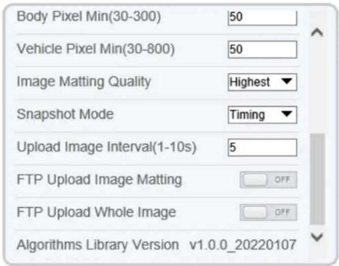
text_image
Body Pixel Min(30-300) 50 Vehicle Pixel Min(30-800) 50 Image Matting Quality Highest Snapshot Mode Timing Upload Image Interval(1-10s) 5 FTP Upload Image Matting OFF FTP Upload Whole Image OFF Algorithms Library Version v1.0.0_20220107Table 10-1 lists the AI multiobject parameters.
Table 10-1 AI multiobject parameters
| Parameter | Description | How to set |
| Face Detection | The camera will snap the face when someone appears in live video. | Enable |
| Fullbody Detection | The camera will snap the whole body when someone appears in live video. | Enable |
| Vehicle Detection | The camera will snap the vehicle when the vehicle appears in live video. | Enable |
| Box Display Mode | Choose one to a trace box will show at live video.There three mode can be chosen. Mode 1: Mode 2: Mode 2: Mode 3 is Mosic. Mode 3 is Mosic. | Choose from drop list. |
| Detection Area | Enable to show the detection area on live video. | |
| Confidence Coefficient | The range of snap image, there are three types, such as high, mid and low. The higher the confidence, the better the snap quality and the fewer snapshots. | Choose from drop list. |
| Face Pixel Min (30-300) | 30-300 pixels, the smaller the pixel be set, the more face will be captured, but it may be mistaken. | Input a value ranges 30 to 300 |
| Body Pixel Min (30-300) | 30-300 pixels, the smaller the pixel be set, the more body will be captured, but it may be mistaken. | Input a value range 30 to 300 |
| Vehicle Pixel Min (30-300) | 30-300 pixels, the smaller the pixel be set, the more face will be captured, but it may be mistaken. | Input a value ranges 30 to 300 |
| Image Matting Quality | The quality of snap image, There are three mode can be chosen, such as low, mid and high. | Choose from drop list. |
| Snapshot Mode | There are three mode can be chosen, such as timing, and optimal. | Choose from drop list. |
| Upload Image Interval (1-10 s) | At timing mode, set the interval of upload image. | Input a value ranges 1 to 10 |
| FTP Upload Image Matting | Configuration > Network Service > FTP, set FTP related parameters, the captured picture will be sent to the set FTP location | Enable |
| FTP Upload Whole Image | Capture a picture and send a whole image. | Enable |
11 Configure the Recording Function

NOTE
Some models may not support SD card, and the recording function is disable, please refer to actual product.
11.1 Record Policy
You can configure the scheduled recording function, alarm recording function, recording quality, and recording rules.
Procedure
Step 1 Choose Configuration > Device Record > Record Policy.
The Record Policy page is displayed, as shown in Figure 11-1.
Figure 11-1 Record policy page

Record Policy
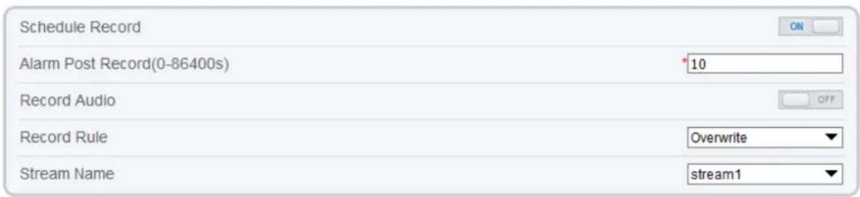
text_image
Schedule Record Alarm Post Record(0-86400s) 10 Record Audio Record Rule Overwrite Stream Name stream1
bar
| Day | Armed | UnArmed | |---|---|---| | Sun | 1 | 0 | | Mon | 1 | 0 | | Tues | 1 | 0 | | Wed | 1 | 0 | | Thur | 1 | 0 | | Fri | 1 | 0 | | Sat | 1 | 0 |
Step 2
Set the parameters according to Table 11-1.
Table 11-1 Recording policy parameters
| Parameter | Description | Setting |
| Schedule Record | Enables schedule record that you can configure the time policy. | [Setting method]Click the button on to enable schedule record.[Default value]OFF |
| Alarm Post Record (0-86400s) | Recording duration (in seconds) after an alarm is generated. | [Setting method]Enter a value manually. |
| Record Audio | Indicates whether to record audios together with videos. | [Setting method]Click the button on to enable record audio. |
| Record Rule | Rule for saving recordings. The options are as follows:Cycle Store: Saves recordings in cycles.Save Days: Duration (in days) for saving a recording. The duration can be a maximum of 99999 days.NOTEThe value 0 indicates that recordings are not overwritten. | [Setting method]Select a value from the drop-down list box. |
| Stream Name | Name of the stream. | [Setting method]Select a value from the drop-down list box. |
Step 3 Configure a recording plan.
You can configure the system to record videos around the clock or in schedule.
For details about how to set Schedule, see 9.5 Step 6.
Step 4 Click Apply.
If the message "Apply success!" is displayed, the system saves the settings.
If other information is displayed, set the parameters correctly.
----End
11.2 Record Directory
Description
Recordings can be stored in an SD card, FTP, or NSA.
Procedure
Step 1 Choose Configuration > Device Record > Record Directory.
The Record Directory page is displayed, there are three types to action disk, such as SD card, FTP, and NAS, as shown in Figure 11-2..
Figure 11-2 Record Directory page

Record Directory
| Disk Type | Disk ID | Group ID | Enable | Total Space(MB) | Free Space (MB) | Alarm Threshold(%) | Status |
| SD Card | 1 | 1 | Yes | 0 | 0 | 100 | N/A |
| FTP | 2 | 1 | No | 0 | 0 | 100 | N/A |
| NAS | 3 | 1 | No | 0 | 0 | 100 | N/A |
Step 2
Set the parameters according to Table 11-2.
Table 11-2 Record directory parameters
| Parameter | Description | Setting |
| Disk Type | Recording directory type, which can be an SD card. | [Setting method]The parameter cannot be set manually. |
| Disk ID | Indicates the Disk ID. | |
| Group ID | Indicates the group HID. | |
| Enable | Indicates whether to enable the recording directory. | |
| Total Space (MB) | Total disk space. | |
| Free Space (MB) | Maximum disk space read automatically. | |
| Alarm Threshold (%) | The camera will alarm when used Space achieves the alarm threshold. | |
| Status | Status of the connection between the current camera and recording directory detected automatically. |
Step 3 Click Modify to modify the parameters of recording path.
Figure 11-3 Record path modify
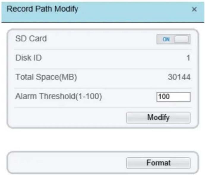
text_image
Record Path Modify SD Card ON Disk ID 1 Total Space(MB) 30144 Alarm Threshold(1-100) 100 Modify Format---End
11.2.1 Configure the SD Card
Procedure
Step 1 Choose Configuration > Device Record > Record Directory.
Step 2 Choose SD Card, click Modify.
The SD card Record Path Modify page is displayed, as shown in Figure 11-4.
Figure 11-4 SD card Record Path Modify page
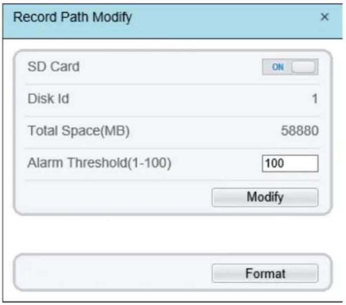
text_image
Record Path Modify SD Card ON Disk Id 1 Total Space(MB) 58880 Alarm Threshold(1-100) 100 Modify FormatStep 3
Set the parameters according to Table 11-3.
Table 11-3 SD card recording parameters
| Parameter | Description | Setting |
| SD Card | Enable SD card to enable record. | [Setting method]Click button to enable SD card. |
| Disk ID | ID of SD card. | N/A |
| Total Space(MB) | Total disk space read automatically. | [Setting method]The parameter cannot be set manually. |
| Alarm Threshold (1-100) | The camera will alarm when used Space achieves the alarm threshold. | [Setting method]Enter a value from 1-100. |
Step 4 Click Apply.
The message "Apply success!" is displayed, and the system saves the settings.
----End
11.2.2 Configure the FTP
Procedure
Step 1 Choose Configuration > Device Record > Record Directory.
Step 2 Choose FTP, click Modify.
The FTP Record Path Modify page is displayed, as shown in Figure 11-5.
Figure 11-5 FTP Record Path Modify page
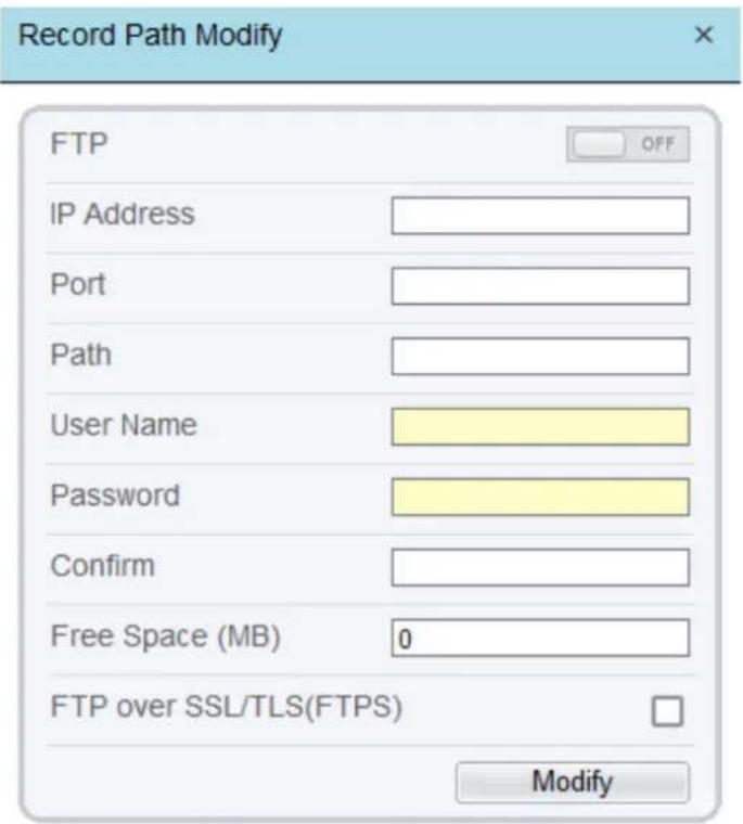
text_image
Record Path Modify FTP IP Address Port Path User Name Password Confirm Free Space (MB) 0 FTP over SSL/TLS(FTPS) ModifyStep 3
Set the parameters according to Table 11-4.
Table 11-4 Recording parameters
| Parameter | Description | Setting |
| FIP | Enable to use FTP (File Transfer Protocol) to record the video. | [Setting method]Enable |
| IP Address | IP address of FTP server. | [Setting method]Enter a value manually. |
| Port | Port of FTP server. | [Setting method]Enter a value manually. |
| Path | FTP Path to save the recording. | [Setting method]Enter a value manually. |
| User Name | FTP server account. | [Setting method]Enter a value manually. |
| Password | FTP server password. | [Setting method]Enter a value manually. |
| Confirm | Confirm the password. | [Setting method]Enter a value manually. |
| Free Space (MB) | The free space of FTP server | [Setting method]Enter a value. |
| FTP over SSL / TLS (FTPS) | Transfer the recording by encryption. | [Setting method]Tick |
Step 4 Click Apply.
The message "Apply success!" is displayed, and the system saves the settings.
----End
11.2.3 Configure the NAS
Procedure
Step 1 Choose Configuration > Device Record > Record Directory.
Step 2 Choose NAS, click Modify.
The NAS Record Path Modify page is displayed, as shown in Figure 11-6.
Figure 11-6 NAS Record Path Modify page

text_image
Record Path Modify NAS IP Address Path User Name Password Confirm File System cifs ModifyStep 3
Set the parameters according to Table 11-5.
Table 11-5 NASrecording parameters
| Parameter | Description | Setting |
| NAS | Enable to use NAS (Network Attached Storage) to record the video. | [Setting method]Enable |
| IP Address | IP address of NAS server. | [Setting method]Enter a value manually. |
| Path | IP address of NAS device. | [Setting method]Enter a value manually. |
| User Name | NAS device account. | [Setting method]Enter a value manually. |
| Password | NAS device Password. | [Setting method]Enter a value manually. |
| Confirm | Confirm the password. | [Setting method]Enter a value manually. |
| File System | There are two types can be chosen, cifs and nfs | [Setting method]Choose from drop-down list.[Default value]cifs |
Step 4 Click Apply.
The message "Apply success!" is displayed, and the system saves the settings.
----End
12 Configure the Privacy Mask Function
Procedure
Step 1 Choose Configuration > Privacy Masking.
The Privacy Masking page is displayed, as shown in Figure 12-1.
Figure 12-1 Privacy Masking page

Privacy Masking
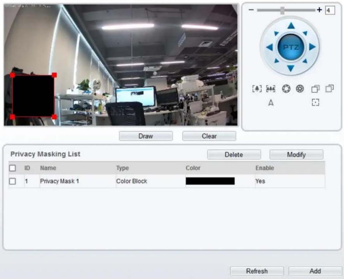
text_image
PTZ Draw Clear Privacy Masking List Delete Modify ID Name Type Color Enable 1 Privacy Mask 1 Color Block Yes Refresh AddStep 2 Click Draw to show the red frame, drag the four corners of rectangle to adjust the position.
Step 3 Click Clear to delete the chosen frame.

NOTE
The maximum percentage of an image that can be masked depends on the device model. Read the tip displayed on the page.
A maximum of four areas can be masked.
Tick the ID of mask area and click Delete to delete the masking.
Step 4 Set the parameters according to Table 12-1.
Table 12-1 Privacy Masking parameters
| Parameter | Description | Setting |
| ID | ID of Privacy Masking. | N/A |
| Name | Name of privacy Masking. | [Setting method]Click the name and enter a value manually.[Default value]Blank |
| Type | Type of privacy masking. | [Setting method]Select a value from the drop-down list box.[Default value]Color Block |
| Color | Color of privacy masking. | [Setting method]Select a value from the drop-down list box.[Default value]Black |
| Enable | Indicates whether to enable the privacy masking. | [Setting method]Select a value from the drop-down list box.[Default value]Yes |
| Delete | Delete a privacy masking. | [Setting method]1. Select a privacy masking from the Privacy Masking List.2. Click Delete, the privacy masking is deleted successfully |
| Modify | Modify a privacy masking. | [Setting method]3. Select a privacy masking from the Privacy Masking List.4. Click a parameter and modify it.5. Click Modify, the privacy masking is modified successfully |
Step 5 Click Add to add privacy masking.
---End
13 Configure the Network Service
13.1 802.1x
Preparation
802.1x authentication must be configured on the access port, which controls to access network resources for the connected users' devices on the port.
Procedure
Step 1 Choose Configuration > Network Service > 802.1x.
The 802.1x page is displayed, as shown in Figure 13-1.
Figure 13-1 802.1x page

802.1x
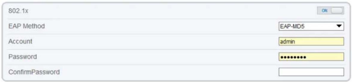
text_image
802.1x EAP Method EAP-MD5 Account admin Password ***** ConfirmPassword
Step 2 Click the button on to enable 802.1x.
Step 3 Choose the EAP Method (Extensible Authentication Protocol) from drop-down list. EAP-MD5 and EAP-TLS can be chosen.
Step 4 Enter the account name.
Step 5 Enter the password and confirm password..
Step 6 Click Apply.
The message "Apply success!" is displayed, and the system saves the settings.
---End
13.2 DDNS
Preparation
Connect the specified camera to the Internet, and obtain the user name and password for logging into the Dynamic Domain Name System (DDNS) server.
Procedure
Step 1 Choose Configuration > Network Service > DDNS.
The DDNS page is displayed, as shown in Figure 13-2.
Figure 13-2 DDNS page

DDNS
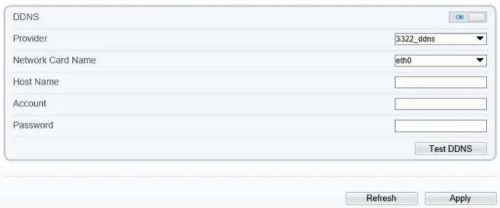
text_image
DDNS Provider 3322_ddns Network Card Name eth0 Host Name Account Password Test DDNS Refresh ApplyStep 2 Click the button on to enable DDNS.
Step 3 Set the parameters according to Table 13-1.
Table 13-1 DDNS parameters
| Parameter | Description | Setting |
| DDNS | Indicates whether to enable the DDNS service. | [Setting method]Click the button on to enable DDNS.[Default value]OFF |
| Provider | DDNS service provider. Currently, only 3322 and dyndns are supported. | [Setting method]Select a value from the drop-down list box.[Default value]3322NOTESet this parameter based on the site requirements. |
| Network Card Name | Name of network card | [Setting method]Select a value from the drop-down list box.[Default value]Eth0 |
| Host Name | Host name is customized by a user. | [Setting method]Enter a value manually.[Default value]Blank |
| Accounts | User name for logging in to the DDNS server. | [Setting method]Enter a value manually.[Default value]Blank |
| Password | Password for logging in to the DDNS server. | [Setting method]Enter a value manually.[Default value]Blank |
Step 4 Click Apply.
If the message "Apply success!" is displayed, and the system saves the settings.
If other information is displayed, set the parameters correctly.
----End
13.3 PPPoE
Preparation
Obtain the PPPoE user name and password from the network carrier.
Description
If a PPPoE connection is used, you need to enter the user name and password on the PPPoE page. After you restart the device, the PPPoE settings take effect and the device obtains a public IP address.
Procedure
Step 1 Choose Configuration > Network Service > PPPoE.
The PPPoE page is displayed, as shown in Figure 13-3.
Figure 13-3 PPPoE page
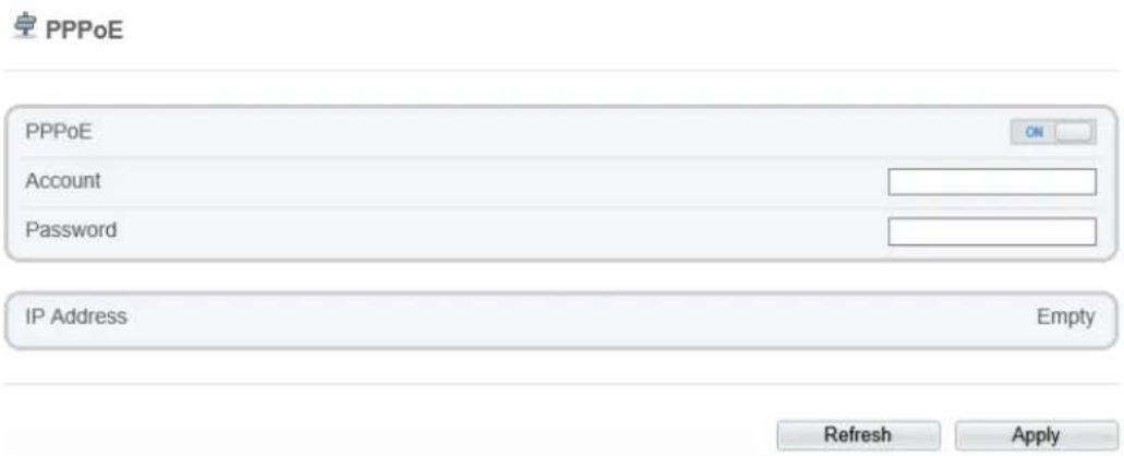
text_image
PPPoE PPPoE ON Account Password IP Address Empty Refresh ApplyStep 2 Click the button on to enable PPPoE.
Step 3 Set the parameters according to Table 13-2.
Table 13-2 PPPoE parameters
| Parameter | Description | Setting |
| PPPoE | Click to enable PPPoE dialing. | [Setting method]Click the button on.[Default value]OFF |
| Accounts | User name of PPPoE provided by the network carrier. | [Setting method]Enter a value manually. |
| Password | Password of PPPoE provided by the network carrier. | [Setting method]Enter a value manually. |
Step 4 Click Apply.
If the message "Apply success!" is displayed, and the system saves the settings.
If other information is displayed, set the parameters correctly.
---End
13.4 Port Mapping
Description
Port mapping helps establish a mapping relationship between the private network and the external network. Port mapping allows outside computers to access intranet devices so that the network works efficiently.
Procedure
Step 1 Choose Configuration > Network Service > Port Mapping.
The Port Mapping page is displayed, as shown in Figure 13-4.
Figure 13-4 PortMapping page
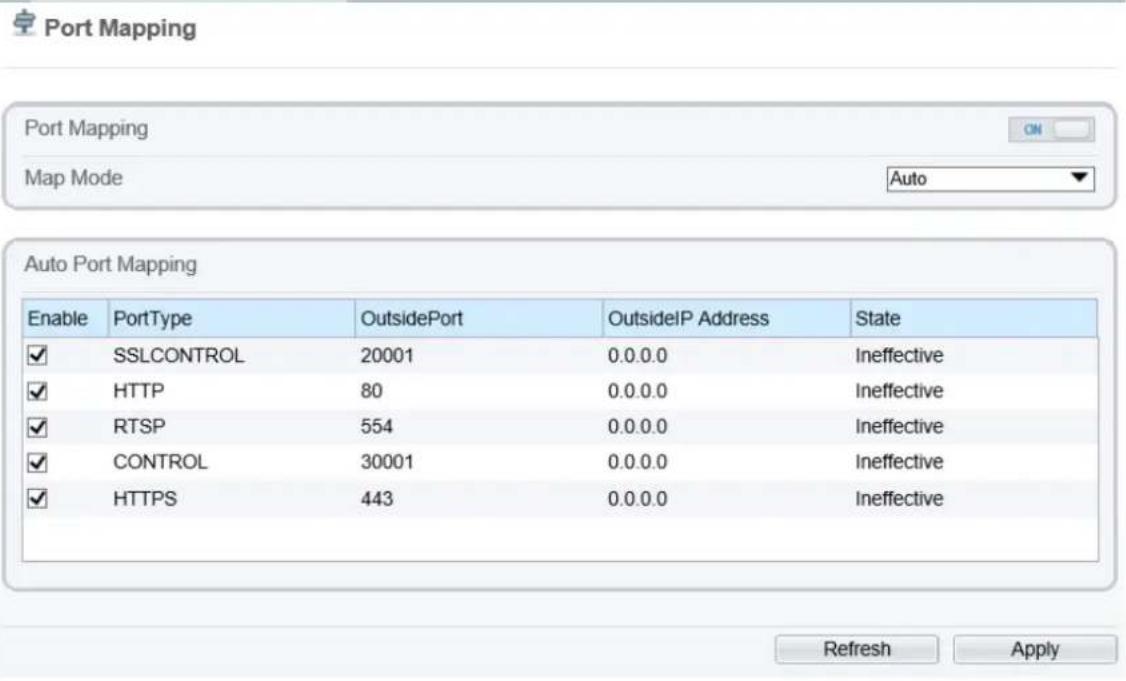
text_image
Port Mapping Map Mode Auto Auto Port Mapping Enable PortType OutsidePort OutsideIP Address State ✓ SSLCONTROL 20001 0.0.0.0 Ineffective ✓ HTTP 80 0.0.0.0 Ineffective ✓ RTSP 554 0.0.0.0 Ineffective ✓ CONTROL 30001 0.0.0.0 Ineffective ✓ HTTPS 443 0.0.0.0 Ineffective Refresh ApplyStep 2 Click the button on to enable Port Mapping.
Step 3 Set the parameters according to Table 13-3.
Table 13-3 Port mapping parameters
| Parameter | Description | Setting |
| Port Mapping | Indicates whether to enable the Port Mapping service. | [Setting method]Click the button on.[Default value]OFF |
| Map Mode | Mode of port mapping, includes auto and manual. | [[Setting method]Select a value from the drop-down list box.[Default value]Auto |
| Port Type | Port Type includes: SSLCONTROL HTTP, RTSP, Control and HTTPS. | N/A |
| Outside Port | Port of outside network. | [Setting method]Enter a value manually in map mode. |
| Outside IP Address | IP address of outside network. | N/A |
| State | Mapping status | N/A |
Step 4 Click Apply.
If the message "Apply success!" is displayed, and the system saves the settings.
If other information is displayed, set the parameters correctly.
----End
13.5 SMTP
Description
If the Simple Mail Transfer Protocol (SMTP) function is enabled, the device automatically sends JPG images and alarm information to specified email addresses when an alarm is generated.
Procedure
Step 1 Choose Configuration > Network Service > SMTP.
The SMTP page is displayed, as shown in Figure 13-5.
Figure 13-5 SMTP page


text_image
SMTP Server Address SMTP Server Port 25 User Name Password Sender E-mail Address Recipient_E-mail_Address1 Recipient_E-mail_Address2 Recipient_E-mail_Address3 Recipient_E-mail_Address4 Recipient_E-mail_Address5 Attachment Image Quality Mid Transport Mode No Encrypt Email Test Refresh ApplyStep 2
Set the parameters according to Table 13-4.

Table 13-4 SMTP parameters
| Parameter | Description | Setting |
| SMTP Server Address | IP address of the SMTP server. | [Setting method]Enter a value manually. |
| SMTP Server Port | Port number of the SMTP server. | [Setting method]Enter a value manually.[Default value]25 |
| User Name | User name of the mailbox for sending emails. | [Setting method]Enter a value manually. |
| Password | Password of the mailbox for sending emails. | [Setting method]Enter a value manually. |
| Sender E-mail Address | Mailbox for sending emails. | [Setting method]Enter a value manually. |
| Recipient_E-mail_Address 1 | (Mandatory) Email address of recipient 1. | [Setting method]Enter a value manually. |
| Recipient_E-mail_Address 2 | (Optional) Email address of recipient 2. | |
| Recipient_E-mail_Address3 | (Optional) Email address of recipient 3. | |
| Recipient_E-mail_Address 4 | (Optional) Email address of recipient 4. | |
| Recipient_E-mail_Address 5 | (Optional) Email address of recipient 5. | |
| Attachment Image Quality | A higher-quality image means more storage space. Set this parameter based on the site requirement. | N/A |
| Transport Mode | Email encryption mode. Set this parameter based on the encryption modes supported by the SMTP server. | [Setting method]Select a value from the drop-down list box.[Default value]No Encrypted |
Step 3 Click Apply.
If the message "Apply success!" is displayed, and the system saves the settings.
If other information is displayed, set the parameters correctly.
---End
13.6 FTP
Description
If the File Transfer Protocol (FTP) button is enabled, the device automatically sends the snapped alarm JPG images to specified FTP server.
Procedure
Step 1 Choose Configuration > Network Service > FTP.
The FTP page is displayed, as shown in Figure 13-6.
Figure 13-6 FTP page

FTP

text_image
FTP Upload FTP Address FTP Port 0 Account Password FTP Path Media Type Snapshot FTP over SSL/TLS(FTPS) Test FTP Refresh ApplyStep 2 Click the button on to enable FTP.
Step 3 Set the parameters according to Table 13-5.
Table 13-5 HP parameters
| Parameter | Description | Setting |
| FTP Upload | Indicates whether to enable the FTP service. | [Setting method]Click the button on.[Default value]OFF |
| FTP Address | IP address of FTP server. | [Setting method]Enter a value manually. |
| FTP Port | Port of FTP server. | [Setting method]N/A[Default value]21 |
| Account | FTP server account. | [Setting method]Enter a value manually. |
| Password | FTP server password. | [Setting method]Enter a value manually. |
| FTP Path | FTP Path to save the JPG image. | [Setting method]Enter a value manually. |
| Media Type | The media type of sending to FTP, snapshot or video clip. | [Setting method]Select a value from the drop-down list box.[Default value]Snapshot |
| FTP over SSL/TLS (FTPS) | Encrypt the files by SSL/TLS when they are be transferred. | [Setting method]Tick |
Step 4 Click Test FTP to verify the parameter, shows “Test succeed”, the parameters are right. If it shows “Test failed”, you need modify the information correctly.
Step 5 Click Apply.
If the message "Apply success!" is displayed, and the system saves the settings.
If other information is displayed, set the parameters correctly.
---End
13.7 IP Filter
Description
Set the IP address in specified network segment to allow access or prohibit access.
Procedure
Step 1 Choose Configuration > Network Service > IP Filter.
The IP Filter page is displayed, as shown in Figure 13-7.
Figure 13-7 IP Filter page

IP Filter
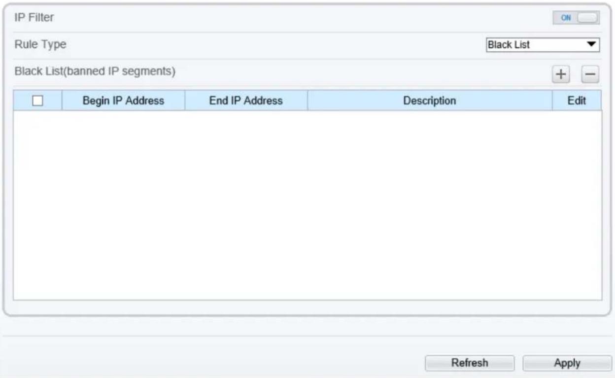
text_image
IP Filter Rule Type Black List Black List(banned IP segments) Begin IP Address End IP Address Description Edit Refresh ApplyStep 2 Click the button on to enable IP Filter.
Step 3 Set the parameters according to Table 13-6
Table 13-6 IP Filter parameters
| Parameter | Description | Setting |
| IP Filter | Indicates whether to enable the IP Filter. | [Setting method]Click the button on.[Default value]OFF |
| Rule Type | IP filter type, includes black list and white list. | [Setting method]Select a value from the drop-down list box.[Default value]Black List |
| Black List | Specified network segment should be banned. | [Setting method]6. Click + to enter the add black/white list page, as shown in Figure 13-87. Enter Begin IP Address.8. Enter End IP Address.9. Enter Descrtption.10.Click OK, the black list added successfully. |
| White List | Allow specified network segment to access. | [Setting method]1. Click + to enter the add black/white list page, as shown in Figure 13-8.2. Enter Begin IP Address.3. Enter End IP Address.4. Enter Descrtption.5. Click OK, add the white list successfully. |
Figure 13-8 Add IP Filter page

text_image
New Begin IP Address End IP Address Description OK Cancel
NOTE
Click ✗ to modify the parameters of setting black list or white. Click — to delete the setting black list or white.
Step 4 Click Apply.
The message "Apply success!" is displayed, and the system saves the settings.
---End
13.8 CGI Alarm Service Center
Description
Device will push the alarm message by CGI with Start URL and End URL, and send to data to CGI Server by HTTP protocol. CGI alarm message is the head of User-Agent of HTTP. Use HTTP protocol
get and send to CGI Server. When need to integrate the CGI alarm message, need to resolve the HTTP Head "User-Agent" to get the data of CGI alarm message.
Procedure
Step 1 Choose Configuration > Network Service > CGI Alarm Service Center.
The CGI Alarm Service Center page is displayed, as shown in Figure 13-9.
Figure 13-9 CGI Alarm Service Center page

CGI Alarm Service Center
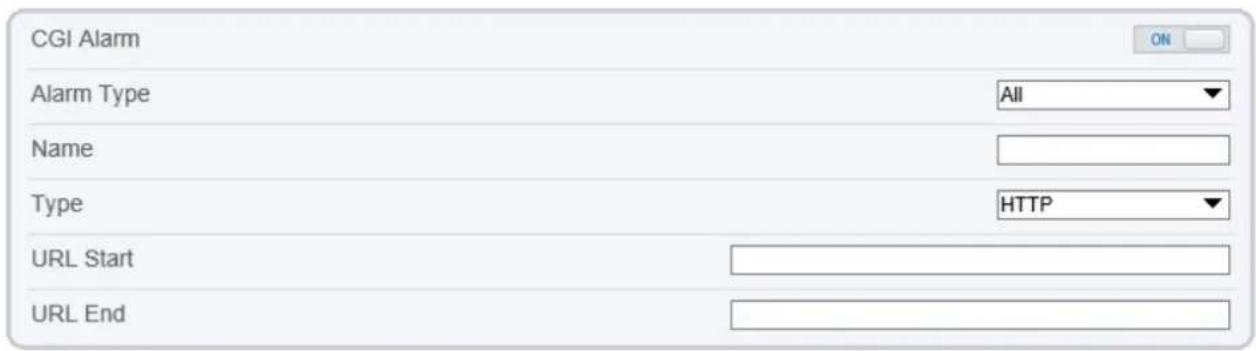
text_image
CGI Alarm Alarm Type All Name Type HTTP URL Start URL End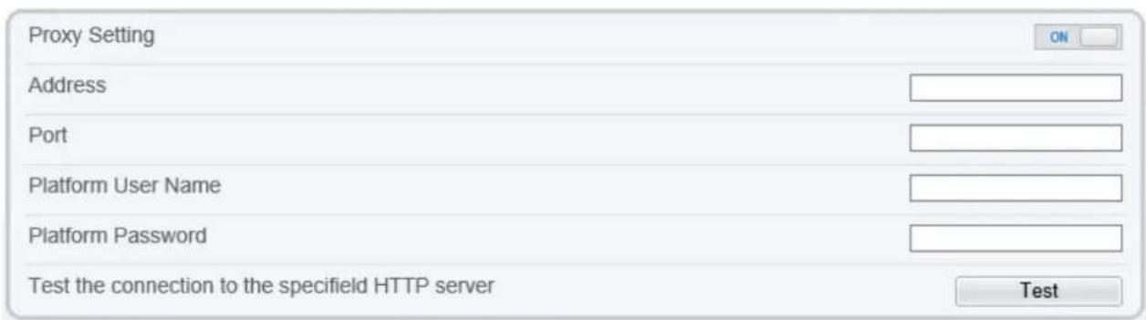
text_image
Proxy Setting Address Port Platform User Name Platform Password Test the connection to the specifield HTTP server Test
Step 2 Click the button on to enable CGI Alarm.
Step 3 Set the parameters according to Table 13-7.
Table 13-7 CGI Alarm Service Center parameters
| Parameter | Description | Setting |
| CGI Alarm | Indicates whether to enable the CGI Alarm. | [Setting method]Click the button on.[Default value]OFF |
| Alarm Type | All alarm types can be chosen, users can choose one to alarm, or choose all. | [Setting method]Select a value from the drop-down list box.[Default value]All |
| Name | Name of CGI Alarm. | [Setting method]Enter a value manually. |
| Type | Type of CGI Alarm. | [Setting method]Select a value from the drop-down list box.[Default value]HTTP |
| URL Start | Push the alarm message by CGI with start URL | [Setting method]Enter a value manually.For example:http://192.168.35.74:80/MajorAlarmType&MinorAlarmType&SourceName&DeviceID&DeviceIP&AlarmTime&Description |
| URL End | Push the alarm message by CGI with end URL | [Setting method]Enter a value manually.For example:http://192.168.35.74:80/MajorAlarmType&MinorAlarmType&SourceName&DeviceID&DeviceIP&AlarmTime&Description |
| Proxy Setting | Indicates whether to enable the Proxy.Forwarder server of CGI alarm to forward the CGI alarm. | [Setting method]Click the button on.[Default value]OFF |
| Address | IP address of Forwarder server. | [Setting method]Enter a value manually. |
| Port | Port of Forwarder server. | [Setting method]Enter a value manually. |
| Platform User Name | User name of forwarder server. | [Setting method]Enter a value manually. |
| Platform Password | Password of forwarder server. | [Setting method]Enter a value manually. |
| Test the connection to the specified HTTP server | Test if the device connects to the proxy successfully. | [Setting method]Click Test, if the device connects to the proxy successfully, the message “Test CGI alarm success” is displayed. |
The message "Apply success!" is displayed, and the system saves the settings. If the message is "Parameter is invalid", you should check if the parameters are correct.
Step 4 Click Apply.
---End
13.9 SNMP
Description
Simple Network Management Protocol (SNMP) is an Internet Standard protocol, supports SNMP v1, SNMPv2c and SNMPv3 network protocol. Choose the proper SNMP protocol version and set the SNMP protocol parameter to collect and organize information about managed devices on IP networks.
Procedure
Step 1 Choose Configuration > Network Service > SNMP.
The SN M P page is displayed, as shown in Figure 13-10.
Figure 13-10 SNMPpage
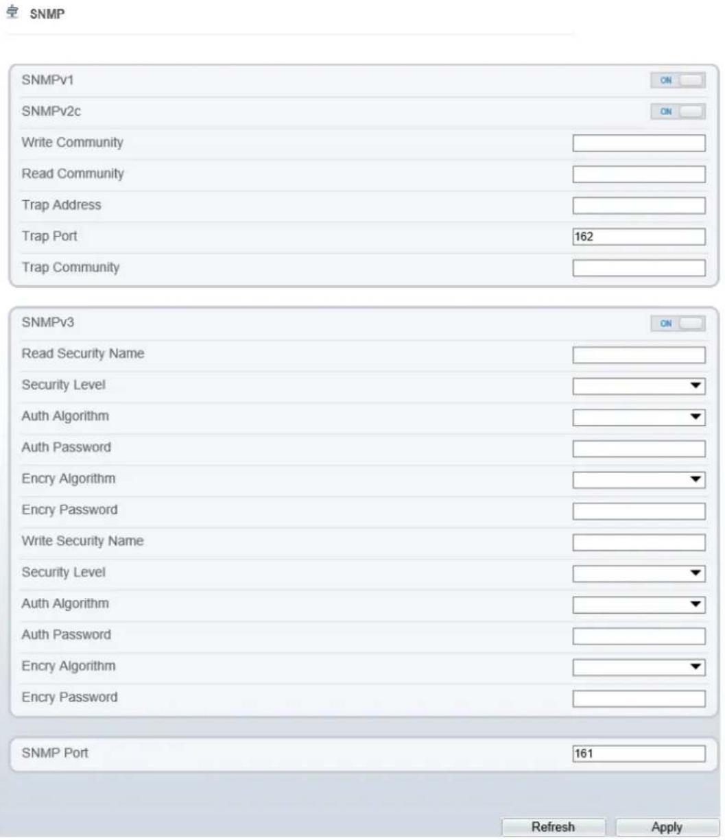
text_image
SNMP SNMPv1 ON SNMPv2c ON Write Community Read Community Trap Address Trap Port 162 Trap Community SNMPv3 ON Read Security Name Security Level Auth Algorithm Auth Password Encry Algorithm Encry Password Write Security Name Security Level Auth Algorithm Auth Password Encry Algorithm Encry Password SNMP Port 161 Refresh ApplyStep 2 Click the button on to enable SNMPv1, SNMPv2C and SNMPv3.
Set the parameters according to Table 13-8.
Table 13-8 SNMPparameters
| Parameter | Description | Setting |
| SNMPv1 | Version of SNMP. SNMPv1 and SNMPv2c use communities to establish trust between managers and agents. Agents support three community names, write community, read community and trap. | [Setting method] Click the button on. [Default value] OFF |
| SNMPv2c | ||
| Write Community | Name of write community. The write community only can modify data. | [Setting method] Enter a value manually. |
| Read Community | Name of read community. The write community only can read data. | |
| Trap Address | IP address of the trap. | |
| Trap Port | Management port of accepting message from trap. | |
| Trap Community | community string of trap. The trap community string allows the manager to receive asynchronous information from the agent. | |
| SNMPv3 | Version of SNMP. SNMPv3 uses community strings, but allows for secure authentication and communication between SNMP manager and agent. | [Setting method] Click the button on. [Default value] OFF |
| Read Security Name | Name of read security. | [Setting method] Enter a value manually. |
| Write Security Name | Name of write security. | |
| Security Level | Security Level between SNMP manager and agent, includes three levels: No auth: No authentication and no encryption Auth: Authentication but no encryption Priv: Authentication and encryption | [Setting method] Select a value from the drop-down list box. [Default value] Blank |
| Auth Algorithm | Authentication Algorithm, includes MD5and SHA. | [Setting method] Select a value from the drop-down list box. [Default value] Blank |
| Auth Password | Authentication password. | [Setting method] Enter a value manually. |
| Encrypt Algorithm | Encryption Algorithm, includes DES and AES. | [Setting method]Select a value from the drop-down list box.[Default value]Blank |
| Encrypt Password | Encryption password. | [Setting method]Enter a value manually. |
| SNMP Port | Port of SNMP. | [Setting method]Enter a value manually.[Default value]161 |
Step 3 Click Apply.
The message "Apply success!" is displayed, and the system saves the settings.
---End
13.10 QOS
Description
If the device is connected to a router or switch with a QOS function, and the priority rule of the corresponding mark is configured on the network device, the network device will preferentially pass the data packet of the corresponding mark.
Procedure
Step 1 Choose Configuration > Network Service > QOS.
The QOS page is displayed, as shown in Figure 13-11.
Figure 13-11 QOS page
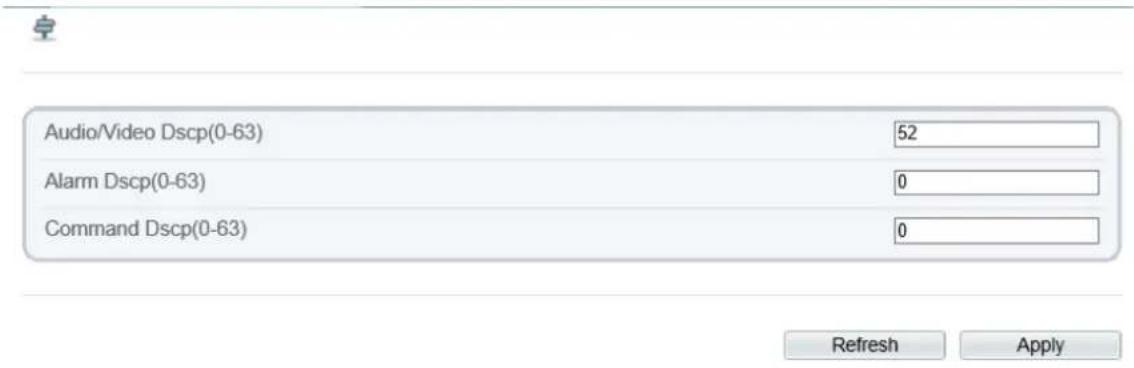
text_image
Audio/Video Dscp(0-63) 52 Alarm Dscp(0-63) 0 Command Dscp(0-63) 0 Refresh ApplyStep 2 Input the value range from 0 to 63( audio/video dscp, alarm dscp and command dscp).
Step 3 Click Apply.
The message "Apply success!" is displayed, and the system saves the settings.
---End
13.11 Platform Access
Description
If the device and platform system are not at the same local network, you can connect device and platform system to the external server. You should build a server for platform in advance, platform's remote IP/Port and IP camera are mapping port to external network.
Procedure
Step 1 Choose Configuration > Network Service > Platform Access.
The Platform Access page is displayed, as shown in Figure 13-12
Figure 13-12 Platform Access page
Platform Access
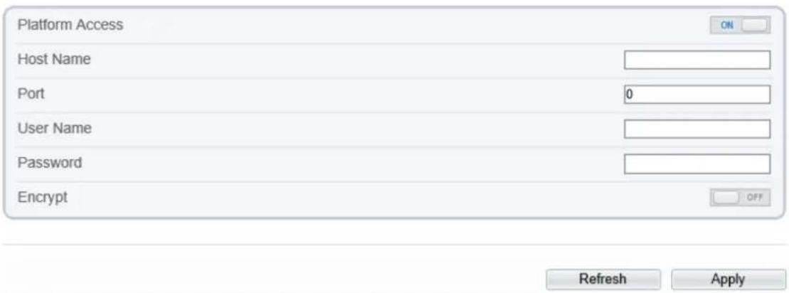
text_image
Platform Access Host Name Port 0 User Name Password Encrypt Refresh ApplyStep 2 Input the parameters. The host name and port are same as the platform, as shown in figure. It is the IP or domain of external network server. The user name and password are same as platform login.

text_image
Basic Information Server Name: CMU_127.0.0.1 Type: CMU IP/Port: 127.0.0.1: 10066 Start-up Time: 2022-04-11 15:15:51 Running State: Online Version: V1.7.1.0.1.0.0_20220331 Remote IP/Port: Log Type: Error F2P status: Office Device registration port: 17888 SSL port: 15680 Domain: Default Domain F2P UUID Remote device registration port:Step 3 Add the IPC to platform, you should input the following information
1: IP/ID/Domain name is device ID of IPC.
2: The connection mode should be chosen Device active registration.

text_image
+ AddDevice Device Name Device Type IPC Protocol Private Protocol IP/ID/ domain name Port 30001 Group Default group Advanced setting Connection mode Device active registration IAU Not Support MDU Auto Save and New Test Add CancelDevice Info
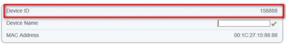
text_image
Device ID 158888 Device Name MAC Address 00:1C:27:15:88:88Step 4 If you want to encrypt the access, you can enable the Encrypt.
Step 5 Click Apply.
The message "Apply success!" is displayed, and the system saves the settings.
---End
14 Privilege Manager
14.1 Configure a User
Description
You can add, modify, and delete a user in privilege manager page.
Procedure
Step 1 Choose Configuration > Privilege Manager > User.
The User page is displayed, as shown in Figure 14-1. Table 14-1 describes the parameters.
Figure 14-1 User Page
User
| ID | User Name | Groups | Notes | Operate |
| 0 | admin | SuperAdmin | admin |
Add
Table 14-1 UserParameters
| Parameter | Description | Setting |
| ID | User ID | N/A |
| User Name | User name for logging in to the camera. | [Setting method]Select a value from the drop-down list box. |
| Groups | Permission group where a user belongs. The default permission groups areSuper Admin, Administrators,Operator, and Media user. Their permissions are described as follows:Super Admin: Includes all privileges.Administrators: Live Video, Video Control, PTZ control, Audio, Playback, Backup, Record Policy, Disk Configure, Privilege Manage, Parameter Configure, System Maintenance and Log,Operator: System Maintenance, Parameter Configure, playback, Live Video and Video Control.Media user: Live Video | [Setting method]ClickAdd, then select a value from the drop-down list box. |
| Notes | Notes of the User. | [Setting method]ClickAdd, then enter a value manually. |
| Operate | The operation of the user, includes view user, modify user and delete user.NOTESuper Admin can be viewed only. | [Setting method]Click the icon as required. |
Step 2 Add, modify, or delete a user as required.
Table 14-2 are specific operations.
Table 14-2 Operation Description
| Function | Procedure | Description |
| Add | 1. Click Add.The Add User page is displayed, as shown in Figure 14-2.2. Enter a user name, password, confirm password.3. Select a group from the drop-down list box.4. Enter the notes (Optional).5. Check the privilege.6. Click OK.The user is added successfully. | Add an administrator or a common user as shown in Figure 14-2. |
| Modify | 1. Click .The Modify User page is displayed.2. Modify the user name, password, group or privilege.3. Click OK.The user is modified successfully. The User page is displayed. | Modify the user name, password, group or privilege. |
| Delete | Select the user from the User list. Click ✗, the message “Confirm to delete?” is displayed, click OK, then the group is deleted successfully. | Delete a user. |
Figure 14-2 Add User Page

text_image
Add User User Name Password ConfirmPassword Group Administrators Notes
text_image
Privilege ✓ Live Video ✓ Video Control ✓ PTZ Control ✓ Audio ✓ Playback ✓ Backup ✓ Record Policy ✓ Disk Config Privilege Description Live view and stream switch.

NOTE
Click the privilege to view the detailed description of function.
---End
15 Configure Protocol Parameters
15.1 Protocol Information
Description
You can view the existing protocol name and version number of the current device on the Configuration > Protocol > Protocol Info page, as shown in Figure 15-1. Table 15-1 describes the protocol-related parameters.
Figure 15-1 Protocol Info page
Protocol Info
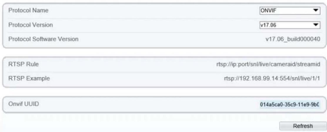
text_image
Protocol Name ONVIF Protocol Version v17.06 Protocol Software Version v17.06_build000040 RTSP Rule rtsp://ip:port/snl/live/cameraid/streamid RTSP Example rtsp://192.168.99.14:554/snl/live/1/1 Onvif UUID 014a5ca0-35c9-11e9-9bc RefreshTable 15-1 Protocol-related parameters
| Parameter | Description |
| Protocol Name | Type of the access protocol. |
| Protocol Version | Version number of the access protocol. |
| Protocol Software Version | Software version number of the access protocol. |
| RTSP Format | URL rule of Real Time Streaming Protocol. |
| RTSP Example | URL example of Real Time Streaming Protocol. |
| Onvif UUID | Universally Unique Identifier. |
15.2 Security Authentication
Description
When an ONVIF-compliant device connects to the platform, you must authenticate the user name and password to ensure the connection security.
Procedure
Step 1 Choose Configuration > Protocol > Security.
The Security page is displayed as shown in Figure 15-2. Table 15-2 describes the parameters on the Security page.
Figure 15-2 Security Page

Security
User Verification

Refresh
Apply
Table 15-2 Parameter Description
| Parameter | Description | Setting |
| User Verification | When you select the User Verification check box, the user name and password must be the same as those for logging in to the device web page. NOTE The default user name is admin, and the default password is admin. | [Setting method]Click the button on to enable User Verification. |
Step 2 Click Apply.
A dialog box is displayed, indicating the parameter configuration success. To make the configuration take effect, click Confirm to restart the device.
---End
15.3 Onvif Configuration
Description
You can view the existing protocol name and version number of the current device on the Configuration > Protocol > Onvif Configuration page, as shown in Figure 15-3. Table 15-3 describes the protocol-related parameters.
Figure 15-3 Onvif Configuration page

Onvif Configuration
| Protocol Name | ONVIF |
| Protocol Version | v22.06 |
| Protocol Software Version | v17.06_build000392 |
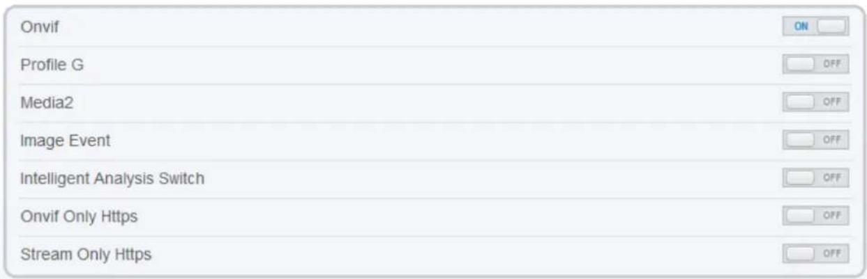
text_image
Onvif Profile G Media2 Image Event Intelligent Analysis Switch Onvif Only Https Stream Only Https
Table 15-3 Protocol-related parameters
| Parameter | Description |
| Protocol Name | Type of the access protocol. |
| Protocol Version | Version number of the access protocol. |
| Protocol Software Version | Software version number of the access protocol. |
| Profile G | Enable ONVFI Profile G |
| Intelligent Analysis Switch | Enable Intelligent Analysis Switch |
| Media 2 | Enable Media 2 |
| Image Event | Enable image event |
| Intelligent Analysis Switch | Enable active onvif |
| Onvif only Https | Onvif can use a more secure HTTPS mode for connection, command interaction and video data transmission, which are transmitted in an encrypted way to enhance network security. |
| Stream only https |
15.4 Multicast Parameters
Description
You can set multicast IP, video port, audio port and source port in multicast parameter page.
Procedure
Step 1 Choose Configuration > Protocol > Multicast Param.
The Multicast Param page is displayed as shown in Figure 15-4. Table 15-4 describes the parameters on the Multicast Param page.
Figure 15-4 Multicast Param page
Multicast Param
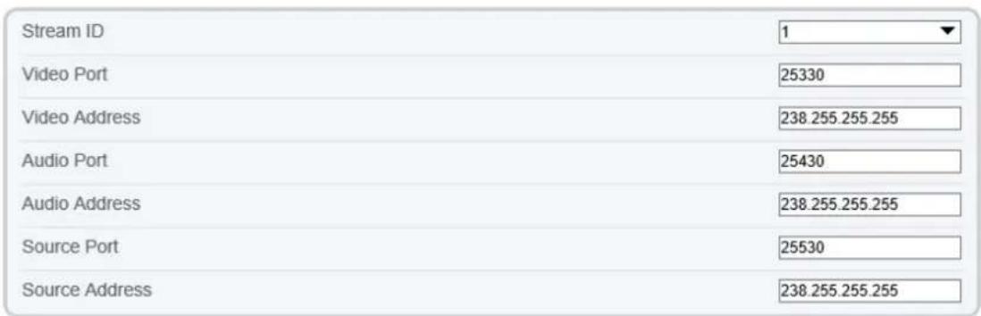
text_image
Stream ID 1 Video Port 25330 Video Address 238.255.255.255 Audio Port 25430 Audio Address 238.255.255.255 Source Port 25530 Source Address 238.255.255.255Refresh Apply
Multicast Param
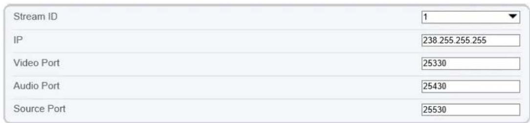
text_image
Stream ID IP 238.255.255.255 Video Port 25330 Audio Port 25430 Source Port 25530Refresh Apply
Table 15-4 Parameter description
| Parameter | Description | Setting |
| Stream ID | ID of stream. | [Setting method]Select a value from the drop-list box.[Default value]1 |
| Video address | IP address that receive multicast data. | [Setting method]Enter a value manually.[Default value]238.255.255.255 |
| Video Port | Port that receive video data. | [Setting method]Enter a value manually.[Default value]25330 |
| Audio Port | Port that receive audio data. | [Setting method]Enter a value manually.[Default value]25430 |
| Source Port | Port that receive source data. | [Setting method]Enter a value manually.[Default value]25530 |
Step 2 Click Apply.
It shows that parameters are set successfully and take effect after restarting., the system will save the settings.
----End
16 Query Device Logs
16.1 Query Operation Logs
Description
Operation logs record user operations and scheduled task commands during the running of the device. Operation logs can be classified into the following types: permission management, system maintenance, device configuration, recording operation, video control, and real-time video.
Procedure
Step 1 Choose Configuration > Device Log > Operation Log.
The Operation Log page is displayed, as shown in Figure 16-1.
Figure 16-1 Operation Log page

Operation Log

text_image
Operation Log All Type Begin Time 2022-04-11 09:43:47 End Time 2022-04-12 09:43:47 Download Query| Time | User Name | Log Info |
| 2022-04-12 09:34:04 | admin | Stop video |
| 2022-04-12 09:34:04 | admin | Stop IntelligenceAnalyse Stream |
| 2022-04-12 08:37:01 | admin | Start IntelligenceAnalyse Stream |
| 2022-04-12 08:37:01 | admin | Start video |
| 2022-04-12 08:36:58 | admin | Login succeed |
| 2022-04-12 06:14:46 | Startup Device | |
| 2022-04-11 20:28:25 | admin | Start AI Multiobject Detect Stream |
| 2022-04-11 20:28:25 | admin | Start video |
| 2022-04-11 20:04:02 | admin | Start AI Multiobject Detect Stream |
| 2022-04-11 20:04:01 | admin | Start video |
Step 2 Set the search criteria.
- Select the type of operation logs to be queried from the System Log drop-down list box.
- Click the Begin Time and End Time text boxes respectively.
A time setting control is displayed.
- Set the start time and end time as required.
- Enter the corresponding user name that is registered with the device from the User Name dropdown list box.
Step 3 Click Query.
The operation logs related to the specified users are displayed.
Step 4 Download the operation logs.
- Set the start time, end time and log type.
- Click Download on the right of the page.
The log link and the message "Please download log by 'save as 'in the right key" are displayed. - Right-click the link and save the logs.

NOTE
An operation log is named as Operation Log by default and in the following format: Operation time user(User name) Operation information For example: 2012-06-20 13:40:39 user() Start Up Device 2012-06-20 13:42:46 user(admin) Configure Device Name 2012-06-20 13:43:16 user(admin) Configure Alarm In
---End
16.2 Query Alarm Logs
Description
An alarm log records information about an alarm generated on a device, including the security, disk, and recording alarms.
Procedure
Step 1 Choose Configuration > Device Log > Alarm Log.
The Alarm Log page is displayed, as shown in Figure 16-2.
Figure 16-2 Alarm Log Page

Alarm Log
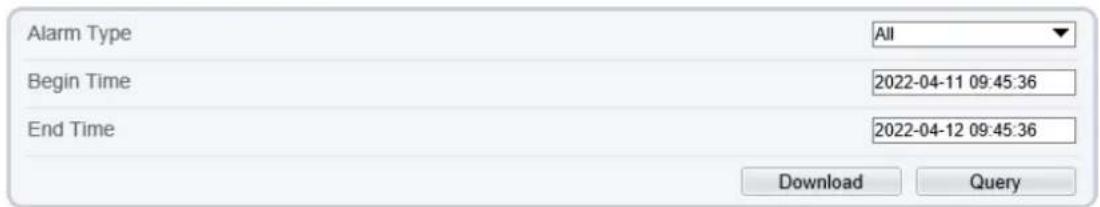
text_image
Alarm Type All Begin Time 2022-04-11 09:45:36 End Time 2022-04-12 09:45:36 Download Query| Alarm Begin Time | Alarm End Time | Log Info | Source ID |
| 2022-04-12 06:14:49 | 2022-04-12 06:14:59 | Record storage failed | 1 |
| 2022-04-11 10:13:36 | 2022-04-11 10:13:46 | Record storage failed | 1 |
Step 2 Set the search criteria.
- Click the Begin Time and End Time text boxes respectively.
A time setting control is displayed.
- Set the start time and end time as required.
- Select the type of the alarm logs to be queried from the Alarm Type drop-down list box.
Step 3 Click Query.
The alarm logs of the specified type are displayed.
Step 4 Download the alarm logs.
- Set the start time and end time.
- Select a log type.
- Click Download on the right of the page.
The log link and the message "Please download log by 'save as 'in the right key" are displayed.
- Right-click the link and save the logs.
NOTE
An alarm log is named as Alarm Info by default and in the following format:
Alarm start time -> Alarm end time Alarm information Source ID
For example:
2012-03-17 16:31:17 -> 2012-03-17 16:32:29 occur motion detect alarm Source Id(1:1)
2012-03-17 16:35:31 -> 2012-03-17 16:35:41 occur motion detect alarm Source Id(1:1)
---End
16.3 Collect All Logs
Description
You can collect logs about a device, which help you analyze and solve possible problems occurring on the device. The logs include overview information, key parameters, operation logs, alarm logs, upgrade logs, and debugging logs.
Procedure
Step 1 Choose Configuration > Device Log > Collect all Log.
The Collect all log page is displayed, as shown in Figure 16-3.
Figure 16-3 Collect Log Page

Collect
Step 2 Collect logs with one click.
- Click Collect, the download page is displayed.
- Select the path to save the logs.
---End
17 Maintain the Device
17.1 Restart a Device
Description
Restart a device including but not limited to the following situations:
The device parameters are set incorrectly, and the device cannot work properly.
A user needs to reset device parameters and make it to take effect.
A device needs to be restarted remotely.
Procedure
Step 1 Choose Configuration > Maintenance.
The Camera Maintenance page is as shown in Figure 17-1.
Figure 17-1 Camera Restart Page

Camera Maintenance
Restart

Auto Restart


Upgrade
Please select firmware file

Upgrade
Reserve IP Setting

Restore to Factory Default

Export Configuration
Download
Import Configuration
Please select file

Upload
Step 2

Click.
The message "Are you sure to restart?" is displayed.
Step 3 Click OK.
The device is restarted successfully five minutes later.
---End
17.2 Auto Restart
Step 1 Choose Configuration > Maintenance.
The Camera Maintenance page is displayed, as shown in Figure 17-1.
Step 2 Enable the auto restart, choose the reboot interval from drop-down list.
There are three option, every day/every week/every month.
Figure 17-2 Camera auto restart

text_image
Auto Restart Reboot Interval Everyday Time 0 : 0Step 3 Click OK.
The device is restarted successfully five minutes later.
---End
17.3 Upgrade the Software Package
Description
You can upgrade the software package from web.
Procedure
Step 1 Choose Configuration > Maintenance.
The Device Maintenance page is displayed.
Step 2 Click ☐ to select the upgrade file.
Step 3 Click Update.
If the message "Upgrade success! The device is rebooting, please login later!" is displayed, the program updated successfully and the device is rebooted.
If other information is displayed, select the upgrade package correctly.

CAUTION
Don't lose power during the upgrade, if the power off, the camera maybe malfunction.
---End
17.4 Restore Device to Factory Settings
Description
You can restore a device to factory settings including but not limited to the following situations:
The device parameters are set incorrectly, and the device cannot work properly.
A user needs to reset device parameters.
All parameters must be restored to the factory settings.

CAUTION
After you clicking , all parameters (you can choose whether to reserve the IP address) will be restored to the factory settings. Use this function carefully.
Procedure
Step 1
Choose Maintenance.
The Device Maintenance page is displayed.
Step 2 Click
The message "Are you sure to restore?" is displayed.
Step 3 Click OK.
The device is restored to the factory settings.
---End
17.5 Export / Import Configuration
Description
You can export configuration to local hard driver, when you configure the same model cameras or the current camera, import the configuration file (config.bin) directly
Procedure
Step 1
Choose Maintenance.
The Device Maintenance page is displayed.
Step 2 Click Download to download the configuration file.
Save the file to local hard driver follow the prompts.
Export configuration
Download
Please download Config by save as in the right key
Download
Step 3 Import configuration: choose the file on local hard driver, click Upload to upload file.
The tip will show after the configuration file uploading finish.
text_image
Tip Upload config file succeeded, The device is rebooting,please login later! OKStep 4
Click OK to finish.
---End
18 Local Configuration
Description
When users download the latest IPC LocalSever, you can set folder to save the snapshots and records to local. If users use no plugin version, this function is invalid.
Procedure
Step 1 Choose Configuration > Local Config.
The Local Config page is displayed, as shown in Figure 18-1.
Figure 18-1 Local Config page

Local Config

text_image
SnapShot Save Path C:\Users\Administrator\Downloads Local Record Save Path C:\Users\Administrator\Downloads Playback performance real time
Step 2 Set snapshot save path.
Step 3 Set local record save path
Step 4 Choose the playback performance, real time or fluent.
Step 5 Click Apply. The message "Apply success!" is displayed, and the system saves the settings.
---End
19 Troubleshooting
Table 19-1 describes the common faults and solutions.
Table 19-1 Common faults and solutions
| Common Fault | Possible Cause | Solution |
| When you enter the device IP address in the address box of Internet Explorer and press Enter, the message "There is a problem with this website's security certificate." is displayed. | The certificate is not installed. | Click Continue to this website (not recommended). |
| The web management system cannot be accessed. | The network is disconnected. | Connect the PC directly to the camera, and verify that the web management system can be accessed.Run the ping command to verify that the camera is reachable. |
| The IP address is used by another device. | Connect the PC directly to the camera and configure the IP address of the camera. | |
| The IP addresses of the PC and IP camera are on different networks. | Check the IP address, subnet mask, and gateway settings on the IP camera, and change the settings as required. | |
| The PTZ or dome cannot be controlled. | The protocol, baud rate, or address is incorrect. | Change the protocol, baud rate, and address in the web management system to those used by the PTZ or dome. |
| The signal cable is not properly connected. | Check the signal strength and connect the signal cable properly. | |
| After the IP camera is upgraded, the web management system cannot be accessed. | The browser cache is not deleted. | To delete the browser cache, proceed as follows:1. Open browser.2. Press Ctrl + Shift +Delete.The Delete Browsing History dialog box is displayed.3. Select all check boxes.4. Click Delete.Login to the web management system again. |
| The IP camera cannot be upgraded. | The network is disconnected.The network settings are incorrect. | Confirm that the upgrade network is connected.Check the network settings. |
| The upgrade package is incorrect. | Obtain the correct upgrade package and upgrade the IP camera again. |
A Acronyms and Abbreviations
| A | |
| ADSL | Asymmetric Digital Subscriber Line |
| C | |
| CBR | Constant Bit Rate |
| CGI | Common Gateway Interface |
| CMS | Central Management System |
| D | |
| DHCP | Dynamic Host Configuration Protocol |
| DNS | Domain Name Server |
| DDNS | Dynamic Domain Name Server |
| E | |
| EAP | Extensible Authentication Protocol |
| F | |
| FTP | File Transfer Protocol |
| G | |
| GAMA | Graphics Assisted Management Application |
| H | |
| HTTP | Hyper Text Transfer Protocol |
| HTTPS | Hypertext Transfer Protocol Secure |
| I | |
| ID | Identity |
| ISO | International Standard Organization |
| IP | Internet Protocol |
| IPC | Internet Protocol Camera |
| L | |
| LPS | Limited Power Source |
| M | |
| MJPEG | Motion Joint Photographic Experts Group |
| MAC | Media Access Control |
| MTU | Media Transmission Unit |
| N | |
| NAS | Network Attached Storage |
| NTP | Network Time Protocol |
| NTSC | National Television Standards Committee |
| O | |
OSD On Screen Display
P
PAL Phase Alteration Line
PoE Power over Ethernet
PPPoE Point-to-Point Protocol over Ethernet
PTZ Pan/Tilt/Zoom
R
ROI Region of Interest
RSTP Rapid Spanning Tree Protocol
S
SMTP Simple Mail Transfer Protocol
SSL Secure Sockets Layer
V
VBR Variable Bit Rate