
Screen Array PIPS - Unspecified CROWN - Free user manual and instructions
Find the device manual for free Screen Array PIPS CROWN in PDF.

| Product Type | Custom two-channel crossover network with equalization (PIP module) |
| Compatible Amplifiers | Crown PIP2-compatible amplifiers (not compatible with older PIP amplifiers) |
| Models | PIP-4622 (for JBL 4622), PIP-3632 (for JBL 3632), PIP-4632 (for JBL 4632) |
| Input Connectors | Electronically balanced 3-position removable terminal block and HD15 connector |
| Input Impedance | 20 kΩ balanced, 10 kΩ unbalanced |
| Signal to Noise Ratio | 90 dB (A-weighted) |
| Attenuation Pad | Defeatable 6.6 dB pad for increased headroom (jumper selectable) |
| Output Monitor | Channel 1 and Channel 2 output voltage monitoring via HD15 |
| Installation | Install into PIP2 opening on amplifier, connect two ribbon cables (20-pin and 18-pin) |
| Warranty | 3 years (parts and labor) |
| Country of Origin | USA (Crown Audio, Elkhart, Indiana) |
| Application | Cinema, studio production, and post-production environments with JBL ScreenArray speakers |
Frequently Asked Questions - Screen Array PIPS CROWN
User questions about Screen Array PIPS CROWN
0 question about this device. Answer the ones you know or ask your own.
Ask a new question about this device
Download the instructions for your Unspecified in PDF format for free! Find your manual Screen Array PIPS - CROWN and take your electronic device back in hand. On this page are published all the documents necessary for the use of your device. Screen Array PIPS by CROWN.
USER MANUAL Screen Array PIPS CROWN
© 2003 by Crown Audio, Inc., P.O. Box 1000, Elkhart, IN 46515-1000 U.S.A. Telephone: 574-294-8000. Fax: 574-294-8329. Trademark Notice: PIP and PIP2 are trademarks; Crown and Amcron are registered trademarks of Crown International. Other trademarks are the property of their respective owners.
Obtaining Other Language Versions:
To obtain information in another language about the use of this product, please contact your local Crown Distributor. If you need assistance locating your local distributor, please contact Crown at 574-294-8200.
Note: The information provided in this manual was deemed accurate as of the publication date. However, updates to this information may have occurred. To obtain the latest version of this manual, please visit the Crown website at www.crownaudio.com.

Printed on recycled paper.
H A Harman International Company
135807-1
2/03

1 Welcome
Crown ScreenArray ^® PIP modules are custom two-channel crossover networks with equalization specifically designed for use with JBL ScreenArray cinema speaker systems installed in cinemas, studio production and post-production environments. The PIP-4622 is designed for use with model 4622 Screen Array system, the PIP-3632 is designed for use with model 3632 Screen Array system, and the PIP-4632 is designed for use with model 4632 Screen Array system.
The ScreenArray PIP modules install into the back of Crown PIP2- compatible amplifiers*, saving rack space and simplifying system wiring.
The HD15 connector on Screen Array PIPs is designed for quick and easy interface with popular cinema monitor products such as the USL CM680.
* You must have a PIP2-compatible amplifier to use the ScreenArray PIP modules. To determine if your amplifier is PIP2-compatible, look for the PIP2 logo on the back of the amplifier. The ScreenArray PIP modules are NOT compatible with older Crown PIP amplifiers.
2 Installation
2.1 Prepare the Amplifier
-
Turn down the level controls (full counterclockwise) and turn off the amplifier.
-
Disconnect the amplifier's power cord.
-
Remove the existing PIP from the amplifier back panel (two screws). This may involve disconnecting the PIP from a PIP2 input adapter. If a PIP2 input adapter is already present, remove the ribbon cables from the adapter.
2.2 Install the PIP into the Amplifier
-
Carefully ground yourself to the chassis of the amplifier before installing the PIP module. It is a good idea to maintain ground contact between yourself and the amplifier while inserting the module into the amplifier.
-
Install the PIP module into the amplifier: Turn the PIP module over so that you can clearly see the two ribbon-cable connectors located on the underside of the circuit board (see Figure 2.1). Connect the two input ribbon cables of the amplifier. The 20-pin cable (A) should be connected first, then the 18-pin cable (B) should be connected.
Both ribbon cables should run smoothly from the amplifier to the PIP card (see Figure 2.1).
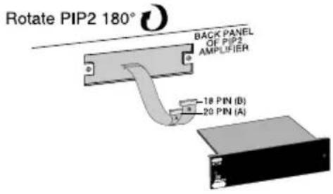
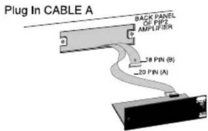


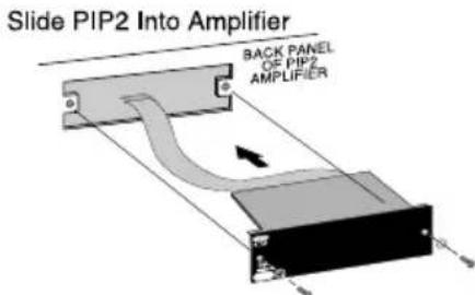
Figure 2.1 Installing the PIP Module

Important: Be careful when attaching the ribbon cable to the connector that the cable is properly seated before applying pressure to the connector.
Forcing the cable onto the connector could cause the keying tabs, which ensure proper pin alignment, to break. Connecting the ribbon cables with improper pin alignments may result in damage to the PIP.
When both cables are firmly attached, turn the PIP module back to an upright position and insert into the PIP opening in the back of the amplifier. Take care while inserting the PIP to make sure you do not crimp, pinch or stretch the ribbon cables.
- Tighten the two PIP mounting screws until the PIP is secured to the amplifier back panel. Be sure to use the supplied star-washers for good ground connection.
2.3 Choice of Input Connector and Pad
The HD15 connector on Screen Array PIPs provides input signal and amplifier output monitoring with popular cinema monitor products such as the USL CM680.
Input and output sensitivity for the USL CM680 and similar products is 3Vrms. This relatively high sensitivity coupled with the gain found in ScreenArray PIPs limits headroom. For example, the PIP-3632 has approximately 11dB of gain at 20 kHz. If the input is 3Vrms at 20 kHz, there is only 2dB of headroom. In the vast majority of systems this reduced headroom will not be a problem.
However, if more headroom is needed, consider using the defeatable 6.6dB pad in the PIP ScreenArray crossovers. When activated, this pad will attenuate an incoming 3Vrms signal to 1.4Vrms- providing approximately 8.6dB for headroom. Jumper Z1 is in the 0dB attenuation position by default (Figure 2.2).
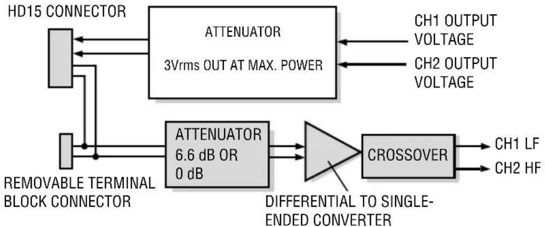
As seen in Figure 2.3, the HD15 connector and the removable terminal are in parallel. Care should be taken to not drive both inputs at once. However, it is acceptable to use the removable terminal connector to "jumper" the input signal to another amplifier if necessary.
When a PIP ScreenArray module is used in conjunction with an USL CM680 or similar product, a single standard VGA cable can be used to provide input audio and output voltage-confidence monitor to and from the amplifier.
A standard VGA cable is a male-to-male cable with High Density 15 pin connectors on each end. VGA cables are readily available at most electronics and computer stores, as they are utilized on almost every computer monitor currently in production. (VGA cables are not included with the PIPs.)
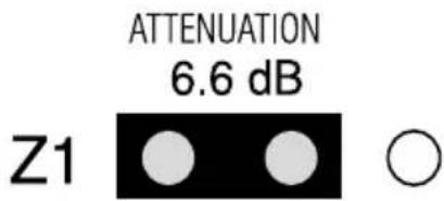

Figure 2.2. Jumper Settings for 6.6 dB Attenuation and 0 dB Attenuation
flowchart
graph LR
    A["HD15 CONNECTOR"] --> B["ATTENUATOR 3Vrms OUT AT MAX. POWER"]
    C["REMOVABLE TERMINAL BLOCK CONNECTOR"] --> D["ATTENUATOR 6.6 dB OR 0 dB"]
    B --> E["CROSSOVER"]
    D --> E
    E --> F["CH1 LF"]
    E --> G["CH2 HF"]
    H["CH1 OUTPUT VOLTAGE"] --> B
    I["CH2 OUTPUT VOLTAGE"] --> B
    J["DIFFERENTIAL TO SINGLE-ENDED CONVERTER"] --> D
Figure 2.3. ScreenArray PIP Block Diagram
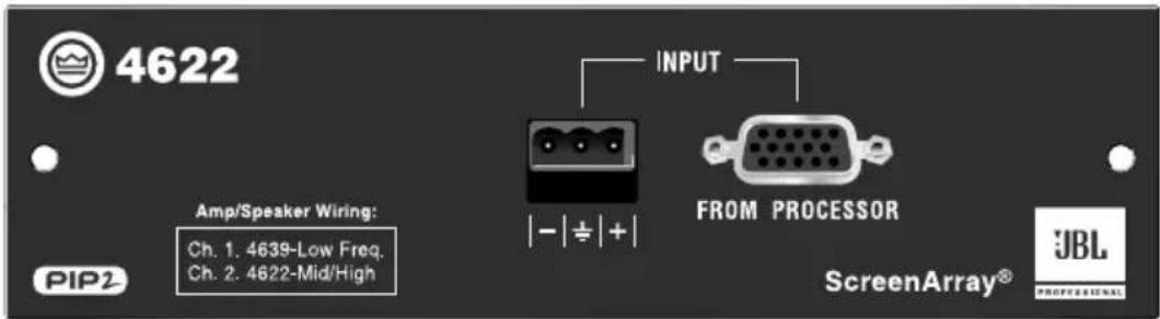
3 PIP-4622
The SST-4622 provides custom crossover and equalization optimized for the JBL ScreenArray model 4622 cinema speaker system.

Figure 3.1 PIP-4622 Front Panel
3.1 System Setup
Connect your system components as shown in Figure 3.2. Connect the cinema processor either to the barrier-block input or the HD15 input. Note: The amplifier should be placed in Stereo (Dual) mode.

Figure 3.2 Stereo Configuration Using a Crown PIP-compatible Amplifier and the PIP-4622 Module
3.2 Specifications
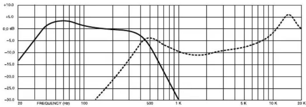
Frequency Response: See Figure 3.3.
Signal to Noise Ratio: 90 dB, A weighted.
Input Impedance: 20 k ohms balanced, 10 k ohms unbalanced.
Connectors
Input: Electronically balanced, 3-position removable terminal block.
line
| FREQUENCY (Hz) | Solid Line (dB) | Dashed Line (dB) | | -------------- | --------------- | ---------------- | | 20 | -15.0 | - | | 100 | 0.0 | - | | 500 | -5.0 | -5.0 | | 1 K | -30.0 | -10.0 | | 5 K | - | -10.0 | | 10 K | - | -5.0 | | 20 K | - | 5.0 |Figure 3.3 PIP-4622 Frequency Response
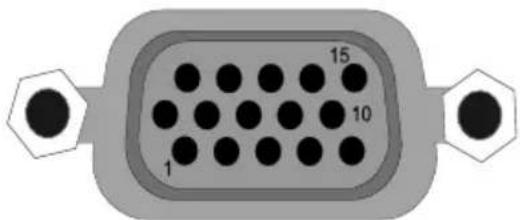
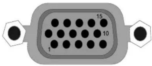
| PIN | PIN | ||
| 1 | Inverting Input | 9 | NC |
| 2 | NC | 10 | Signal Ground |
| 3 | Ch1 Output Voltage Monitor | 11 | NC |
| 4 | NC | 12 | NC |
| 5 | NC | 13 | Ch2 Output Voltage Monitor |
| 6 | Chassis Ground | 14 | NC |
| 7 | Non-Inverting Input | 15 | NC |
| 8 | NC | ||
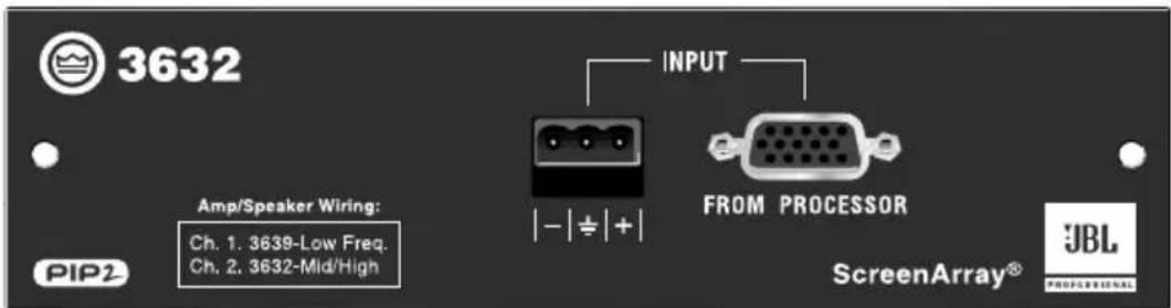
4 PIP-3632
The PIP-3632 provides custom crossover and equalization optimized for the JBL ScreenArray model 3632 cinema speaker system.

Figure 4.1 PIP-3632 Front Panel
4.1 System Setup
Connect your system components as shown in Figure 4.2. Connect the cinema processor either to the barrier-block input or the HD15 input. Note: The amplifier should be placed in Stereo (Dual) mode.
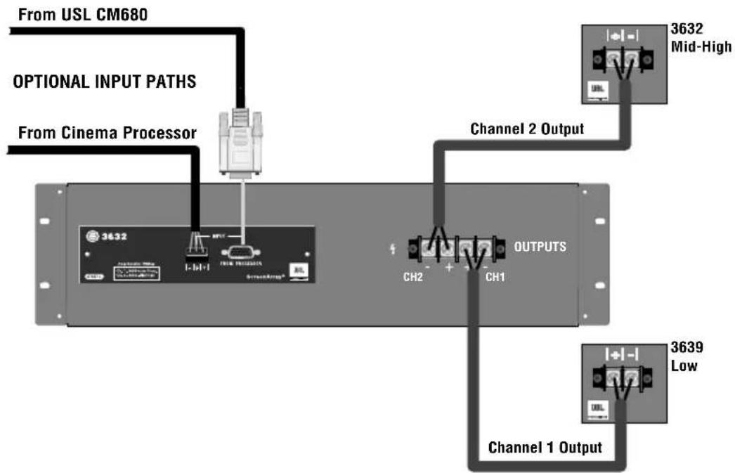
flowchart
graph TD
    A["From USL CM680"] --> B["Optional Input Paths"]
    C["From Cinema Processor"] --> B
    B --> D["Channel 1 Output"]
    D --> E["3639 Low"]
    D --> F["3632 Mid-High"]
    G["CH2"] --> H["OUTPUTS"]
    I["CH1"] --> H
    J["OUTPUTS"] --> K["Channel 2 Output"]
Figure 4.2 Stereo Configuration Using a Crown PIP-compatible Amplifier and the PIP-3632 Module
4.2 Specifications
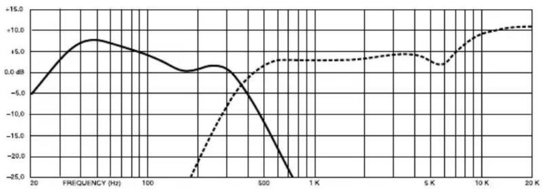
Frequency Response: See Figure 4.3.
Signal to Noise Ratio: 90 dB, A weighted.
Input Impedance: 20 k ohms balanced, 10 k ohms unbalanced.
Connectors
Input: Electronically balanced, 3-position removable terminal block.
line
| FREQUENCY (Hz) | Solid Line (dB) | Dashed Line (dB) | | -------------- | --------------- | ---------------- | | 20 | -6.0 | - | | 100 | +8.0 | - | | 500 | - | +3.0 | | 1K | - | +4.0 | | 5K | - | +3.5 | | 10K | - | +10.0 | | 20K | - | +11.0 |Figure 4.3 PIP-3632 Frequency Response

| PIN | PIN | ||
| 1 | Inverting Input | 9 | NC |
| 2 | NC | 10 | Signal Ground |
| 3 | Ch1 Output Voltage Monitor | 11 | NC |
| 4 | NC | 12 | NC |
| 5 | NC | 13 | Ch2 Output Voltage Monitor |
| 6 | Chassis Ground | 14 | NC |
| 7 | Non-Inverting Input | 15 | NC |
| 8 | NC | ||
5 PIP-4632
The PIP-4632 provides custom crossover and equalization optimized for the JBL ScreenArray model 4632 cinema speaker system.
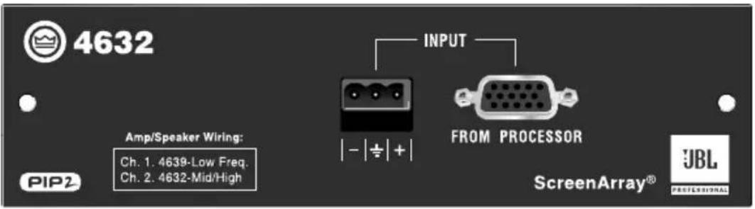
Figure 5.1 PIP-4632 Front Panel
5.1 System Setup
Connect your system components as shown in Figure 6.2. Connect the cinema processor either to the barrier-block input or the HD15 input. Note: The amplifier should be placed in Stereo (Dual) mode.

Figure 5.2 Stereo Configuration Using a Crown PIP-compatible Amplifier and the PIP-4632 Module
5.2 Specifications
Frequency Response: See Figure 5.3.
Signal to Noise Ratio: 90 dB, A weighted.
Input Impedance: 20 k ohms balanced, 10 k ohms unbalanced.
Connectors
Input: Electronically balanced, 3-position removable terminal block.

line
| FREQUENCY (Hz) | Solid Line (dB) | Dashed Line (dB) | | -------------- | --------------- | ---------------- | | 20 | -15.0 | - | | 100 | 0.0 | -30.0 | | 500 | -25.0 | -5.0 | | 1K | - | -5.0 | | 5K | - | -2.5 | | 10K | - | 0.0 | | 20K | - | 5.0 |Figure 5.3 PIP-4632 Frequency Response
PIN
| 1 | Inverting Input | 9 | NC |
| 2 | NC | 10 | Signal Ground |
| 3 | Ch1 Output Voltage Monitor | 11 | NC |
| 4 | NC | 12 | NC |
| 5 | NC | 13 | Ch2 Output Voltage Monitor |
| 6 | Chassis Ground | 14 | NC |
| 7 | Non-Inverting Input | 15 | NC |
| 8 | NC |
Typical 5.1 System

CONNECTIONS
USL Bsl / Bsr to bottom CTs 2000
USL Ls / Rs to middle CTs 2000
USL SW to top CTs 2000
USL RI / Rh to bottom CTs 1200
USL Cl / Ch to middle CTs 1200
USL LI / Lh to top CTs 1200
USL "Main inputs from processor outputs" to
Dolby CP650 "Main audio output"
6 Service
6.1 Worldwide Service
Service must be done at the Crown factory. Contact your local distributor for more information.
6.2 US and Canada Service
Service must be done at the Crown factory (see Sections 6.3 and 6.3.1). It is important that you have your copy of the bill of sale as your proof of purchase.
6.3 Factory Service
To obtain factory service, fill out the service information page found in the back of this manual and send it along with your proof of purchase and the defective unit to the Crown factory.
For warranty service, we will pay for ground shipping both ways in the United States. Contact Crown Factory Service to obtain prepaid shipping labels prior to sending the unit. Or, if you prefer, you may prepay the cost of shipping, and Crown will reimburse you. Send copies of the shipping receipts to Crown to receive reimbursement.
Your repaired unit will be returned via UPS ground. Please contact us if other arrangements are required.
6.3.1 Factory Service Shipping Instructions
- Before sending a Crown product to the factory for service, first call Crown Factory Service for a return authorization (RA) number.
- Be sure to fill out the service information form that follows and enclose it with your shipment, either inside the box or in a packing slip envelope securely attached to the outside of the shipping carton. Do not send the service information form separately. If you are sending the unit from a Shipping Center, we recommend taping the form to the product. We also recommend recording the serial number and model before shipping for your reference.
- To ensure the safe transportation of your unit to the factory, ship it in an original factory packing container.

natural_image
Simple line drawing of an open box with the word 'crown' on the front face (no other text or symbols)If you don't have the original carton, you may obtain a product service foam-in-place shipping pack from Crown Factory Service at the number listed below. For non-warranty service, you may also provide your own shipping pack, however we still recommend using a Crown supplied shipping container. Minimum recommended requirements for materials are as follows: 275 P.S.I. burst test Double-Wall carton that allows for 2-inch solid Styrofoam on all six sides of unit or 3 inches of plastic bubble wrap on all six sides of unit; securely seal the package with an adequate carton sealing tape. Do not use light boxes or "peanuts." Damage caused by poor packing cannot be covered under warranty.
- Do not ship the unit in any kind of cabinet (wood or metal). Ignoring this warning may result in extensive damage to the unit and the cabinet. Accessories are not needed—do not send the product documentation, cables and other hardware.
If you have any questions, please contact Crown Factory Service.
Crown Factory Service
1718 W. Mishawaka Rd.
Elkhart, Indiana 46517 U.S.A.
Telephone:
574-294-8200
800-342-6939 (North America,
Puerto Rico, and Virgin Islands only)
Facsimile:
574-294-8301 (Technical Support)
574-294-8124 (Factory Service)
Internet:
http://www.crownaudio.com
7 Warranty

UNITED STATES & CANADA
SUMMARY OF WARRANTY
Crown International, 1718 West Mishawaka Road, Elkhart, Indiana 46517-4095 U.S.A. warrants to you, the ORIGINAL PURCHASER and ANY SUBSEQUENT OWNER of each NEW Crown product, for a period of three (3) years from the date of purchase by the original purchaser (the "warranty period") that the new Crown product is free of defects in materials and workmanship. We further warrant the new Crown product regardless of the reason for failure, except as excluded in this Warranty.
ITEMS EXCLUDED FROM THIS CROWN WARRANTY
This Crown Warranty is in effect only for failure of a new Crown product which occurred within the Warranty Period. It does not cover any product which has been damaged because of any intentional misuse, accident, negligence, or loss which is covered under any of your insurance contracts. This Crown Warranty also does not extend to the new Crown product if the serial number has been defaced, altered, or removed.
WHAT THE WARRANTOR WILL DO
We will remedy any defect, regardless of the reason for failure (except as excluded), by repair, replacement, or refund. We may not elect refund unless you agree, or unless we are unable to provide replacement, and repair is not practical or cannot be timely made. If a refund is elected, then you must make the defective or malfunctioning product available to us free and clear of all liens or other encuMbrances. The refund will be equal to the actual purchase price, not including interest, insurance, closing costs, and other finance charges less a reasonable depreciation on the product from the date of original purchase. Warranty work can only be performed at our authorized service centers or at the factory. Warranty work for some products can only be performed at our factory. We will remedy the defect and ship the product from the service center or our factory within a reasonable time after receipt of the defective product at our authorized service center or our factory. All expenses in remedying the defect, including surface shipping costs in the United States, will be borne by us. (You must bear the expense of shipping the product between any foreign country and the port of entry in the United States and all taxes, duties, and other customs fees for such foreign shipments.)
HOW TO OBTAIN WARRANTY SERVICE
You must notify us of your need for warranty service within the warranty period. All components must be shipped in a factory pack, which, if needed, may be obtained from us free of charge. Corrective action will be taken within a reasonable time of the date of receipt of the defective product by us or our authorized service center. If the repairs made by us or our authorized service center are not satisfactory, notify us or our authorized service center immediately.
DISCLAIMER OF CONSEQUENTIAL & INCIDENTAL DAMAGES
YOU ARE NOT ENTITLED TO RECOVER FROM US ANY INCIDENTAL DAMAGES RESULTING FROM ANY DEFECT IN THE NEW CROWN PRODUCT. THIS INCLUDES ANY DAMAGE TO ANOTHER PRODUCT OR PRODUCTS RESULTING FROM SUCH A DEFECT. SOME STATES DO NOT ALLOW THE EXCLUSION OR LIMITATIONS OF INCIDENTAL OR CONSEQUENTIAL DAMAGES, SO THE ABOVE LIMITATION OR EXCLUSION MAY NOT APPLY TO YOU.
WARRANTY ALTERATIONS
No person has the authority to enlarge, amend, or modify this Crown Warranty. This Crown Warranty is not extended by the length of time which you are deprived of the use of the new Crown product. Repairs and replacement parts provided under the terms of this Crown Warranty shall carry only the unexpired portion of this Crown Warranty.
DESIGN CHANGES
We reserve the right to change the design of any product from time to time without notice and with no obligation to make corresponding changes in products previously manufactured.
LEGAL REMEDIES OF PURCHASER
THIS CROWN WARRANTY GIVES YOU SPECIFIC LEGAL RIGHTS, YOU MAY ALSO HAVE OTHER RIGHTS WHICH VARY FROM STATE TO STATE. No action to enforce this Crown Warranty shall be commenced later than ninety (90) days after expiration of the warranty period.
THIS STATEMENT OF WARRANTY SUPERSEDES ANY OTHERS CONTAINED IN THIS MANUAL FOR CROWN PRODUCTS. 12/01

WORLDWIDE EXCEPT USA & CANADA
SUMMARY OF WARRANTY
Crown International, 1718 West Mishawaka Road, Elkhart, Indiana 46517-4095 U.S.A. warrants to you, the ORIGINAL PURCHASER and ANY SUBSEQUENT OWNER of each NEW Crown1 product, for a period of three (3) years from the date of purchase by the original purchaser (the "warranty period") that the new Crown product is free of defects in materials and workmanship, and we further warrant the new Crown product regardless of the reason for failure, except as excluded in this Crown Warranty.
1 Note: If your unit bears the name "Amcron," please substitute it for the name "Crown" in this warranty.
ITEMS EXCLUDED FROM THIS CROWN WARRANTY
This Crown Warranty is in effect only for failure of a new Crown product which occurred within the Warranty Period. It does not cover any product which has been damaged because of any intentional misuse, accident, negligence, or loss which is covered under any of your insurance contracts. This Crown Warranty also does not extend to the new Crown product if the serial number has been defaced, altered, or removed.
WHAT THE WARRANTOR WILL DO
We will remedy any defect, regardless of the reason for failure (except as excluded), by repair, replacement, or refund. We may not elect refund unless you agree, or unless we are unable to provide replacement, and repair is not practical or cannot be timely made. If a refund is elected, then you must make the defective or malfunctioning product available to us free and clear of all liens or other encuMbrances. The refund will be equal to the actual purchase price, not including interest, insurance, closing costs, and other finance charges less a reasonable depreciation on the product from the date of original purchase. Warranty work can only be performed at our authorized service centers. We will remedy the defect and ship the product from the service center within a reasonable time after receipt of the defective product at our authorized service center.
HOW TO OBTAIN WARRANTY SERVICE
You must notify us of your need for warranty service within the warranty period. All components must be shipped in a factory pack. Corrective action will be taken within a reasonable time of the date of receipt of the defective product by our authorized service center. If the repairs made by our authorized service center are not satisfactory, notify our authorized service center immediately.
DISCLAIMER OF CONSEQUENTIAL & INCIDENTAL DAMAGES
YOU ARE NOT ENTITLED TO RECOVER FROM US ANY INCIDENTAL DAMAGES RESULTING FROM ANY DEFECT IN THE NEW CROWN PRODUCT. THIS INCLUDES ANY DAMAGE TO ANOTHER PRODUCT OR PRODUCTS RESULTING FROM SUCH A DEFECT.
WARRANTY ALTERATIONS
No person has the authority to enlarge, amend, or modify this Crown Warranty. This Crown Warranty is not extended by the length of time which you are deprived of the use of the new Crown product. Repairs and replacement parts provided under the terms of this Crown Warranty shall carry only the unexpired portion of this Crown Warranty.
DESIGN CHANGES
We reserve the right to change the design of any product from time to time without notice and with no obligation to make corresponding changes in products previously manufactured.
LEGAL REMEDIES OF PURCHASER
No action to enforce this Crown Warranty shall be commenced later than ninety (90) days after expiration of the warranty period.
THIS STATEMENT OF WARRANTY SUPERSEDES ANY OTHERS CONTAINED IN THIS MANUAL FOR CROWN PRODUCTS. 7/01
Crown Factory Service Information
Shipping Address: Crown Factory Service,
1718 W. Mishawaka Rd., Elkhart, IN U.S.A. 46517
Phone: 1-800-342-6939 or 1-574-294-8200 Fax: 1-574-294-8124
Owner's Name: ____
Shipping Address: ____
Phone Number: ____ Fax Number: ____
Email: ____
Model: ____ Serial Number: ____
Purchase Date: ____
RA Number: ____
NATURE OF PROBLEM
(Be sure to describe the conditions that existed when the problem occurred and what attempts were made to correct it.)
Other equipment in your system:
If warranty has expired, payment will be:
○ Cash/Check ○ VISA ○ MasterCard ○ C.O.D.
o P.O. for Crown Dealer
Card Number:
Exp. Date: ____
Signature:
ENCLOSE THIS PORTION WITH THE UNIT.
DO NOT MAIL SEPARATELY.

crown
H A Harman International Company
- Obtaining Other Language Versions:
- Welcome
- Installation
- Prepare the Amplifier
- Install the PIP into the Amplifier
- Choice of Input Connector and Pad
- PIP-4622
- System Setup
- Specifications
- Connectors
- PIP-3632
- System Setup
- Specifications
- PIP-4632
- System Setup
- Specifications
- CONNECTIONS
- Service
- Worldwide Service
- US and Canada Service
- Factory Service
- Factory Service Shipping Instructions
- Crown Factory Service
- Telephone:
- Facsimile:
- Internet:
- Warranty
- UNITED STATES & CANADA
- SUMMARY OF WARRANTY
- ITEMS EXCLUDED FROM THIS CROWN WARRANTY
- WHAT THE WARRANTOR WILL DO
- HOW TO OBTAIN WARRANTY SERVICE
- DISCLAIMER OF CONSEQUENTIAL & INCIDENTAL DAMAGES
- WARRANTY ALTERATIONS
- DESIGN CHANGES
- LEGAL REMEDIES OF PURCHASER
- WORLDWIDE EXCEPT USA & CANADA
- Crown Factory Service Information
- NATURE OF PROBLEM
- crown
Brand : CROWN
Model : Screen Array PIPS
Category : Unspecified