CS-UE18ZKF-3 - Air-conditioner PANASONIC - Free user manual and instructions
Find the device manual for free CS-UE18ZKF-3 PANASONIC in PDF.

User questions about CS-UE18ZKF-3 PANASONIC
0 question about this device. Answer the ones you know or ask your own.
Ask a new question about this device
Download the instructions for your Air-conditioner in PDF format for free! Find your manual CS-UE18ZKF-3 - PANASONIC and take your electronic device back in hand. On this page are published all the documents necessary for the use of your device. CS-UE18ZKF-3 by PANASONIC.
USER MANUAL CS-UE18ZKF-3 PANASONIC
Operating Instructions
Air Conditioner

natural_image
Front view of a Panasonic air conditioner unit with digital display (no text or symbols on body)Model No.
Outdoor Unit
CU-UE12ZKF-3
CU-UE18ZKF-3
CU-UE24ZKF-3
Indoor Unit
CS-UE12ZKF-3
CS-UE18ZKF-3
CS-UE24ZKF-3

دليل المستخدم
مکیف هواء
Thank you for purchasing Panasonic Air Conditioner, operating instructions attached.
Before operating the unit, read these operating instructions thoroughly and keep them for future reference.
Name and Address of importer:
Panasonic Marketing Middle East & Africa FZE
P.O.Box No. 17985, Jebel Ali, Dubai, U.A.E
English
Quick guide
 | Inserting the batteries1 Pull out the back cover of remote control2 Insert AAA or R03 batteries (can be used ~ 1 year)3 Close the cover |
 | Basic operationSelect the desired temperature• Selection range: 16 °C ~ 28 °C.• Operating the unit within the recommended temperature may save energy: 26 °C ~ 28 °C.• Use remote control within 8 m from the remote control receiver of the indoor unit. |
 | |
| The illustrations in this manual are for explanation purposes only and may differ from the actual unit. They are subject to change without notice for future improvement. |
English
Table of contents
| Safety precautions | 2-3 |
| Cleaning instructions | 4-15 |
| Troubleshooting | 16 |
| Information | Back cover |
Accessories
- Remote control
• AAA or R03 batteries × 2
Safety Precautions
Important Safety Instructions
To prevent injury or property damage or both, following instructions must be followed. Incorrect operation due to non-compliance of instructions may cause harm or damage.
The safety precautions listed here are divided into two categories. In either case, important safety information is listed which must be read carefully and followed.
Warning  | This signs warns of death or serious injury |
Caution  | This signs warns of injury or damage to property |
The instructions to be followed are classified by the following symbols:

This symbol denotes an action that is PROHIBITED.


These symbols denote actions COMPULSORY.

flowchart
graph TD
    A["Air inlet"] --> B["Air outlet"]
    B --> C["Outdoor unit"]
    D["Indoor unit"] --> E["Remote control"]
    F["Power supply"] --> G["Air inlet"]
    G --> H["Air outlet"]
    I["Air outlet"] --> J["Air inlet"]
    K["Air inlet"] --> L["Air outlet"]

WARNING
Indoor unit and outdoor unit

Unit should not be used by children and people with reduced physical sensory, mental illness, lack of knowledge & experience unless they are supervised by an authorized person responsible for their safety and they are aware about the hazards involved. Children should not play with the appliance.
Always consult an authorized agent for repair, maintenance, service or re-installation. Improper repair and maintenance activity may result in water leak, electric shock or fire.
Always consult an authorized dealer to confirm regarding the usage of specific type of refrigerant. Using a refrigerant other than that specified may result in injury due explosion or damage to appliance

Do not install the unit in a potentially explosive or flammable atmosphere, failure to do so may result in fire.
Do not insert your finger or other objects into the air conditioner indoor or outdoor unit, rotating parts may cause injury.

Do not touch the outdoor unit during lightning, it may result in electric shock.
Do not expose your self directly to the cold air for long time, it may affect your health.
Do not sit or step on the unit, you may fall accidentally.
Remote Control


Do not allow infants and children to play with the remote they may accidentally solve the batteries.
Power Supply

Do not use modified cord, joint cord, extension cord or unspecified cord to prevent overheating of fire.


To prevent possibility of overheating, fire or electric shock:
- Do not share the same power outlet with other equipment.
• Do not operate with wet hands.
• Do not over bend the power supply cord - Do not operate or stop the unit by inserting or pulling out the power plug.

Use complete power cord without joints. In situations where the usage of complete power cord without joints is not possible, use and approved connection means. For example, socket and plug.

flowchart
graph TD
    A["Power Supply"] --> B["Air Conditioner"]
    B --> C["Indoor Unit"]
    B --> D["Outdoor Unit"]
    E["Complete wire without joining OR"] --> F["Approved connecting means (for example: approved socket and plug)"]
    F --> G["Complete wire without joining"]
- If the power cord is damage it must be replaced by the manufacturer or authorized service agent or a similarly qualified person in order to avoid hazard
- It is strongly recommended to install an earth leakage circuit breaker (ELCB) or residual circuit device (RCD) to prevent electric shock or fire.
• To prevent overheating, fire or electric shock, - Insert the power plug power properly
- Dust on the power plug should be periodically wiped with a dry cloth.
- Insert the power plug power properly
- Dust on the power plug should be periodically wiped with a dry cloth.
In case any abnormality or failure is observed immediately disconnect the power supply and remove the plug from the socket. Examples of abnormalities or failures:
• The ELCB trips frequently
• Burning smell is observed
• Anormal noise or vibration in the unit is observed
• Water leak from the indoor unit
• Power cord or plug becomes abnormally hot.
• Fan speed cannot be controlled
- Unit stops running immediately even if the power supply is on.
• Fan does not stop even if the operation is stopped.

This equipment must be earthed to prevent any possibility of electric shock or fire.

Switch off the power supply and remove the plug from the socket during following situations:
• Before cleaning or servicing
- When unit is expected to remain out of use for long period of time
• During abnormal condition such as lightning.


Caution
Indoor unit and outdoor unit

- Do not wash the indoor unit with water, benzene, thinner or any other scouring powder, it may damage the unit or cause corrosion.
- Do not use the unit for preservation of precise equipment, food, animal, plants, artwork or other objects.
- Do not use any combustible material in front of the air outlet, it may cause fire propagation.
• Do not expose plants or pets directly to the airflow. - Do not touch the sharp aluminum fins or other sharp parts, it may cause injury.

- Do not switch on the indoor unit when waxing the floor. After waxing the floor area, aerate (ventilate) the room properly before operating the unit.
- Do not install the unit in oily and smoky areas, it may damage the unit.
- Do not dismantle unit for cleaning or any other purpose by yourself, it may cause injury.
- Do not step onto an unstable platform when cleaning the unit, you may fall accidentally.
- Do not replace a vase or water container on the unit, water may enter the unit and degrade the insulation, this may result in electric shock.
- Do not open the window or door for long time during dry/cool mode operation.

Prevent water leakage by ensuring that drainpipe is
- Connected properly
• Clear from obstruction (like mud accumulation in pipe)
• Not immersed in water
• After a long period of use or use with any combustible material ventilate the room.
- Regularly inspect the installation rack / mountings / bench to ensure that it is in good condition and there is no danger of the unit falling.
- Connected properly - Clear from obstruction (like mud accumulation in pipe) - Not immersed in water - After a long period of use or use with any combustible material ventilate the room. - Regularly inspect the installation rack / mountings / bench to ensure that it is in good condition and there is no danger of the unit falling.
Remote Control

Do not use any rechargeable battery (e.g., Ni-Cd) as it may damage the remote control

To prevent any malfunction or damage to remote control:
- Remove the batteries in the unit if the unit is expected to be out of use for long time.
• Use batteries of same type.
- Insert the batteries observing polarity.
- Remove the batteries in the unit if the unit is expected to be out of use for long time. - Use batteries of same type. - Insert the batteries observing polarity.
Power Supply

Do not disconnect the plug by pulling the cord, it may result in electric shock.
NAMES OF PARTS
| INDOOR UNIT | |
| No. | Description |
| 1 | Front panel |
| 2 | Air filter |
| 3 | Optional filter (if installed) |
| 4 | LED Indicator |
| 5 | Signal receiver |
| 6 | Terminal block cover |
| 7 | Ionizer generator(if installed) |
| 8 | Vanes |
| 9 | Emergency button |
| 10 | Indoor unit rating label (Stick position optional) |
| 11 | Airflow direction louver |
| 12 | Remote controller |

text_image
INDOOR UNIT 1 2-3 4-5 Panasonic 10 6 11 10 9 8 7 12| OUTDOOR UNIT | |
| No. | Description |
| 13 | Air outlet grille |
| 14 | Outdoor unit rating label |
| 15 | Terminal block cover |
| 16 | Gas valve |
| 17 | Liquid valve |
| 18 | Caution lable (DO NOT STEP ON) |

text_image
13 18 14 15 16 17 OUTDOOR UNITNote: Figures shown here are for explanation purpose only and may differ from actual model
INDOOR UNIT INDICATOR

text_image
5 3 1 2 4 88
text_image
1—□.□ 2 3| No. | LED | Function |
| 1 | Indicator for timer, temperature and error codes. | |
| 2 | Timer operation | |
| 3 | Sleep mode | |
| 4 | This symbol appears when the unit is in operation and disappears when switched off | |
| 5 | Symbol appears during power on time (stand by). |
Note: Shape and position of switches / buttons indicated here may differ from actual model, but they function is same.
REMOTE CONTROL
AUTO RESTART FUNCTION
The appliance is preset with auto restart function by the manufacturer. In case of a sudden power failure the module memorize all the setting set by user. when the power supply is stored, the unit will start automatically with all the previous settings saved by the memory function.
To deactivate auto restart function, proceed as follows: 1.
- Switch the air conditioner off and unplug from the main supply.
- Re-plug the unit and press emergency button.
- Keep pressing the emergency button till you hear 4 short beeps from the unit. AUTO-RESTART function is deactivated.
To activate the AUTO-RESTART function follow the same process till you hear 3 short beeps.
EMERGENCY FUNCTION
In case the remote control is not functioning, please proceed as follows:
Open and lift the front panel up to an angle that makes emergency button within your reach:
- One press will activate forced cooling operation.
- Two press within 3 sec will activate forced heating function.
- To switch off the unit, long press the emergency button.
- After 30 minutes in forced operation, the air conditioner will switch to cooling mode with set temperature of 23^ C and fan speed will be in AUTO mode.
I-FEEL function is described later in the manual.

text_image
display PCB Emergency button front panel front panelThe emergency button in some models could be on the right part of the unit under the front panel.
Note:
- Shape and position of switches / buttons indicated here may differ from actual model, but they function is same.
- External static pressure for all heat pump models is 0 Pa.
REMOTE CONTROL
Remote control DISPLAY
| No. | Symbols | Meaning |
| 1 |  | Battery indicator |
| 2 | [HEX6] | Auto Mode |
| 3 |  | Cooling Mode |
| 4 | [30Y7] | Dry Mode |
| 5 | [337A] | Fan only Mode |
| 6 |  | Heating Mode |
| 7 |  | ECO Mode |
| 8 | [348Z] | Timer |
| 9 |  | Temperature indicator |
| 10 | Fan speed:Auto/ low/ low-mid/ mid/ mid-high/ high | |
| 11 |  | Mute function |
| 12 | [2AC7] | TURBO function |
| 13 | [AHC4] | Up-down auto swing |
| 14 | [244Z] | Left-right auto swing |
| 15 |  | SLEEP function |
| 16 | [083X] | Health function |
| 17 | [8CZ6] | I FEEL function |
| 18 | [1707] | Signal indicator |
| 19 | [177Z] | Gentle wind |
| 20 |  | Child-Lock |
| 21 | [2VISA] | Display ON/OFF |
| 22 | [7444] | Anti-Mildew |

text_image
0.0.0 0.0.0 h + - MODE TURBO SWING TEMP FAN MUTE ECO TIMER SLEEP I FEEL DISPLAY
text_image
00.0 80.0 h MODE TURBO SWING TEMP FAN MUTE ECO TIMER SLEEP ANTI- MILDEW DISPLAYNote: Display and some functions on remote control may differ from model to model.
REMOTE CONTROL
| S. No | Key/Button Function | |
| 1 To | turn ON/OFF the unit | |
| 2 To | increase temperature or time setting | |
| 3 To | decrease temperature or time setting | |
| 4 MODE To select mode of operation (AUTO/COOL/DRY/FAN/HEAT) | ||
| 5 | ECO | To activate/deactivate the ECO function |
| Long press to activate/deactivate the 8°C heating function (Not availabel in all models) | ||
| 6 TURBO To activate/deactivate the TURBO function | ||
| 7 FAN To select fan speed AUTO/LOW/MID/HIGH | ||
| 8 TIMER To select timer function ON/OFF | ||
| 9 SLEEP To activate/deactivate the SLEEP function | ||
| 10 DISPLAY To switch ON/OFF the LED display | ||
| 11 | SWING | To STOP/START horizontal louver movement or set the desired direction of flow UP/DOWN |
| 12 | SWING | To STOP/START vertical louver movement or set the desired direction of flow LEFT/RIGHT |
| 13 | I-FEEL | To activate/deactivate the I-FEEL function (Not availabel in all models) |
| 14 | MUTE | To activate/deactivate the MUTE function |
| Long press to activate/deactivate theGEN function (Not availabel in all models) | ||
| 15 | ANTI-MILDEW | To activate/deactivate the ANTI-MILDEW function |
| 16 | MODE + TIMER | To activate/deactivate the CHILD-LOCK function |
| 17 | SWING ◇+ SWING<> | To activate/deactivate the SELF-CLEAN function (Not availabel in all models) |
| 18 | FAN + MUTE | To activate/deactivate the GENTLE WIND function (Not availabel in all models) |
| 19 | SLEEP + DISPLAY | To activate/deactivate the HEALTH function (Not availabel in all models) |
Note:
1. Display and some functions on remote control may differ from model to model.
2. Shape and position of switches / buttons indicated here may differ from actual model, but they function is same.
3. Unit confirm the correct reception of each signal by beep sound.
REMOTE CONTROL
Replacement of Batteries
- Remove the battery cover from the rear of the remote control by sliding it in the direction shown by the arrow.
• Put the batteries in place according to the direction as shown in the remote control
• Put the back cover in place by sliding it into the slot provided.

• Use two quantity LRO3 AAA (1.5V) batteries.
• Do not use rechargeable batteries.
- Replace the old batteries with the new one of same type when display is no longer legible.
- Do not dispose the batteries as unsorted municipal waste, collection of such waste separately for special treatment is necessary.

natural_image
Diagram of a remote control device showing battery, casing, and battery pack assembly (no text or labels)
In some models of remote control additional manual switch is provided at the back of the remote control in the battery section. This switch can be operated as shown below:
| DIP switch on position | Function |
| °C | The display is adjusted in degree celsius. |
| °F | The display is adjusted in degree fahrenheit. |
| Cool | The display is adjusted in only cooling mode |
| Heat | The display is adjusted in cooling and heating mode |

natural_image
Technical line drawing of a remote control casing with internal components and a separate inset showing two rectangular slots (no text or symbols)
- Direct the remote control towards the air conditioner.
- Ensure that there is no object between remote controller and signal receptor in the indoor unit.
- Do not expose the remote controller to sun rays.
- Keep the remote controller at least 1m away from television and other electrical appliances.
REMOTE CONTROL
Cooling Mode
The cooling function allows the air conditioner to cool the room and at the same time reduce the humidity in air.
To activate the cooling function (COOL), press MODE button till the symbol ✦ appears on the display.
The cooling cycle is activated by setting the temperature lower than that of the room.
To optimize the performance of air conditioner, adjust:
-
Temperature
-
Fan speed
-
Direction of air
FAN Mode
To activate FAN mode, press MODE button till the symbol ✿ appears on the display. In FAN mode only air ventilation happens.
DRY Mode
This functions reduces the humidity in the room. To set DRY mode, press MODE key till appears on display. An automatic cycle of cooling and fan mode is activated.
AUTO Mode
This means automatic mode. To activate AUTO model press MODE button till the symbol appears on display.
In this mode run will be set automatically depending on room temperature.
Heating Mode
The heating function allows the air conditioner to produce hot air. To activate the heating function (HEAT), press MODE button till the symbol appears on the display.
The heating cycle is activated by setting the temperature higher than that of the room.
To optimize the performance of air conditioner, adjust:
- Temperature
- Fan speed
- Direction of air

In HEATING operation, appliance can automatically activate a defrost cycle, which is essential to free the condenser from excessive deposit of frost. This procedure usually last for 2-10 minutes. During defrost fan stops operation. After defrosting is completed, unit will return to HEATING mode.

The appliance is fitted with a hot smart function, which allows appliance to startup in few seconds and ensure immediate output of hot air.
FAN Speed
With this function user can change the speed of fan. Press FAN button and change the speed.
Fan speed will change in cycle as AUTO / MUTE / LOW / LOW-MID / MID / HIGH-MID / HIGH / TURBO.

flowchart
graph LR
    A["Flash"] --> B["→"]
    B --> C["→"]
    C --> D["→"]
    D --> E["→"]
    E --> F["→"]
    F --> G["→"]
    G --> H["→"]
    H --> I["→"]
    I --> J["→"]
    J --> K["→"]
    K --> L["→"]
    L --> M["→"]
    M --> N["→"]
    N --> O["→"]
    O --> P["→"]
    P --> Q["→"]
    Q --> R["→"]
    R --> S["→"]
    S --> T["→"]
    T --> U["→"]
    U --> V["→"]
    V --> W["→"]
    W --> X["→"]
    X --> Y["→"]
Child Lock
Long press MODE and TIMER key together to activate this function., repeat the same step to deactivate.
Once activated no key will function on remote.
REMOTE CONTROL
TIMER MODE - TIMER ON
TIMER
To automatically switch on the appliance
ON-TIMER can be set only when unit is off. To set the time of automatic switch on please follow the steps below:
- Press button for the first time to set the switch on time, symbol and will appear on the remote display.
- Press button ^ or ∨ to set desired on time. Each time you press the button the time will increase/decrease by half an hour between 0 and 10 and by 1 hour between 10 and 24 hours.
- Press TIMER button again to confirm.
- After setting the ON time, select the desired the desired mode (COOL / HEAT / AUTO / FAN / DRY), fan speed and temperature.
Press TIMER button again to cancel.
TIMER MODE – TIMER OFF
TIMER
To automatically switch off the appliance
ON-TIMER can be set only when unit is on. To set the time of automatic switch on please follow the steps below:
- Press TIMER button for the first time to set the switch off time, symbol and will appear on the remote display.
- Press button ^ or ∨ to set desired on time. Press TIMER button again to confirm.
Press TIMER button again to cancel.
SWING FUNCTION


- Press this swing button to activate the louvers:
1.1 Press SWING to activate the horizontal louvers, they swing in up and down direction. Symbol will appear on the remote display.
Press again to stop the swing movement at the current angle.
1.2 Press SWING ( ) to activate the horizontal louvers, they swing in up and down direction. Symbol will appear on the remote display.
Press again to stop the swing movement at the current angle. - Do not adjust the vertical louvers manually in models which have mechanically controlled vertical louvers, doing so may damage the delicate link mechanism.
- Press horizontal swing and vertical swing together to activate self cleaning function (this feature is available in selected models).

- Louver adjustment must be done when the unit is switched off.
- Never put your finger, stick or other object in the air inlet or outlet. Accidental contact with live parts may cause serious injury.
TURBO FUNCTION
TURBO

To activate TURBO function, press the TURBO button and symbol will appear on the display. To cancel press again.
In cool heat mode when you select TURBO feature the unit will on quick cool or quick heat mode and operate at the highest fan speed to blow strong air flow.
REMOTE CONTROL
MUTE FUNCTION ECO FUNCTION
MUTE
- Press MUTE button to active this function, symbol will appear on the remote display. Press gain to deactivate.
- During mute function, the remote controller will display AUTO FAN speed and the indoor will run at lowest fan speed to give a quiet atmosphere.
- When other functions such as FAN / TURBO are operated during MUTE operation, the MUTE function will get cancelled. MUTE function cannot be operated during DRY mode.
SLEEP FUNCTION
SLEEP
Press SLEEP button to active SLEEP function, symbol 📍 will appear on the display. Press again to cancel.
After 10 hours of running in SLEEP mode the unit will shift to previously set mode.
I-FEEL FUNCTION (Optional)
I FEEL
Press I-FEEL button to active I-FEEL function, symbol will appear on the display. Press again to cancel.
This function enables remote controller to check the room temperature at its current location and send this signal to unit. Now unit will optimize the flow to give a comfortable atmosphere.
This function will get deactivated after 2 hours.
ECO

Appliance automatically sets the operation to save energy
Press ECO button to active ECO function, will appear on the display. Press again to cancel.
Note: ECO function is available in both cooling and heating mode.
DISPLAY FUNCTION
DISPLAY
Switch ON/OFF the LED display on panel.
Press DISPLAY button to switch OF the LED display on the panel. Press again to switch ON.
ANTI-MILDEW FUNCTION (Optional)
ANTI- MILDEW

Press ANTI-MILDEW button to active this function, symbol Ⓧ will appear on the display. Press again to cancel.
After running on COOL / DRY mode for more than 30 minutes you can activate this function. During this function unit will blow strong airflow to dry the inner parts of unit to prevent dew formation and then unit will shut down.
Note: ANTI-MILDEW function is only available during DRY / COOLING mode.
REMOTE CONTROL
SELF CLEAN FUNCTION (Optional)
This function is available only in few heat pump inverter models.
To activate this function, turn OFF the indoor unit and press and button together at the same time till you hear a beep sound. Symbol [AC] will appear on the remote display and LED display.
- This function helps to clear the accumulated dirt, bacteria etc. from the indoor evaporator.
- This function runs for 30 minutes, and unit returns to previously set mode after that.
Press button to cancel this function during the process. You will hear 2 beeps when the function is finished or cancelled.

- It is normal for the unit to have noise during this operation as plastic material expands when heated and contracts when cooled.

• We suggest operation this function at following ambient conditions to avoid certain safety protection features.
| Indoor unit | Temp < 86°F (30°C) |
| Outdoor unit | 41°F (5°C) < Temp < 86°F (30°C) |

- It is suggested to use this function every 3 months
8°C HEATING FUNCTION (Optional)
- Long press ECO button for over 3 seconds to activate this function, symbol 8^ ( 46^ ) will appear on the display.
- This function will start the heating mode when room temperature is lower than 8^ C ( 46^ F) and will return to standby when temperature reached 9^ C ( 48^ F).
- If the room temperature is higher than 18^ C ( 64^ F), appliance will cancel this function automatically.
GENTLE WIND FUNCTION (Optional)
- Turn ON the unit and switch to COOL mode, long press FAN and MUTE button together for 3 seconds to activate GENTLE WIND function, symbol will appear on the display. Press again to deactivate.
- This function will auto close the vertical flaps and give a comfortable gentle wind feeling.
HEALTH FUNCTION (Optional)
- Turn ON the unit and long press SLEEP and DISPLAY button together for 3 seconds to activate this function, symbol will appear on the display. Press again to deactivate.
- During HEALTH function, Ionizer / Plasma / Bipolar Ionizer / UVC lights (depending on availability in model) will be activated.
GEN FUNCTION (Optional)
- Turn ON the unit and long press MUTE button for 3 seconds to activate this function, press again to deactivate.
- Under this function short press MUTE button to select the general type L3-L2-L1-OF.
- Select OF and wait for 2 seconds to exit.
Any attempt to use this unit under temperature conditions beyond the specified range may cause the air conditioner protection device to start and unit may fail to operate. Therefore, ensure to use the air conditioner within the specified limits as mentioned below:
Fixed air conditioner:
| Temperature\MODE | Heating | Cooling | Dry |
| Room temperature | 0°C~27°C | 17°C~32°C | |
| Outdoor temperature | -7°C~24°C | T1 climate: 15°C~43°C | |
| T3 climate: 15°C~52°C | |||
Inverter air conditioner:
| Temperature\MODE | Heating | Cooling | Dry |
| Room temperature | 0°C~27°C | 17°C~32°C | |
| Outdoor temperature | -15°C~24°C(Low temperature heating: -20°C~24°C) | T1 climate: 15°C~50°C(Low temperature cooling: -15°C~50°C) | |
| T3 climate: 15°C~55°C | |||
In case of power cut when the units restarts after supply is restored or if the user switch the mode of operation from one mode to another, the compressor protection device is activated. In this case compressor resumes operation after 3 minutes.

Characteristics of heating operation (applicable to heat pump models)
Pre-heating:
When heating function is activated, the indoor unit takes 2-5 minutes for preheating, after that the unit will start heating and blow warm air.
Defrosting:
During heating function frost is slowly accumulated on outdoor unit, under this situation the unit will switch to defrost mode automatically to improve heating effect. During defrost cycle indoor and outdoor fan will stop running. Unit will resume heating once defrosts cycle is completed.

Emergency button:
Open the panel and find the emergency button on the control box. Use this button when remote control fails to operate. (Always press emergency button with insulated material).
| Current Status Operation Response Enter Mode | |||
| Stand by | Press emergency button once | Beeps once Cooling | |
| Stand by (For heat pumps) | Press emergency button twice in 3 sec | Beeps twice Heating | |
| Running | Press emergency button once | Beeps for a while OFF | |

text_image
control-box cover ON/OFF (open the panel of indoor unit)MAINTENANCE
| WARNING | Before cleaning ensure to shut down the unit and remove the plug from the socket.Never flush the air conditioner with water.Liquids (e.g., thinner or gasoline) damage the unit, so use only soft dry cloth or wet cloth dipped with neutral detergents to clean the unit.Regularly clean the filter. If the unit is operating in dusty environment, ensure to clean the filter frequently as required.After removing the filter screen, ensure not to touch the fins of coil. Failure to do so may result in injury. |
| CLEAN THE UNIT | 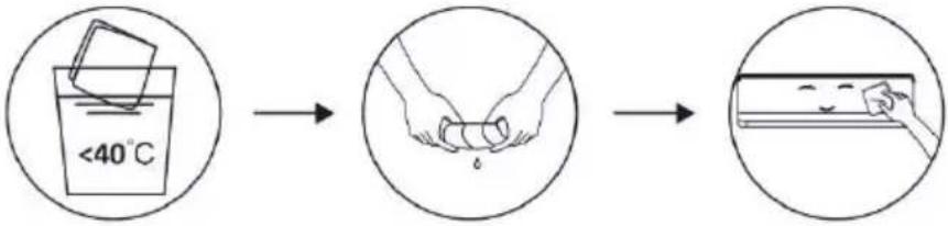 Note: Frequently clean the unit to keep it clean and tidy. Note: Frequently clean the unit to keep it clean and tidy. |
| CLEAN THE FILTERS |  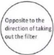 Take out the filter Clean the filter with Assemble the filter from the unit soap water and dry it back on the unitNote: Whenever you notice duct accumulation on the filter, ensure to clean it for healthy and efficient operation Take out the filter Clean the filter with Assemble the filter from the unit soap water and dry it back on the unitNote: Whenever you notice duct accumulation on the filter, ensure to clean it for healthy and efficient operation |
| SERVICE AND MAINTENANCE | If the air conditioner is expected to remain out of use for long time, ensure to remove the batteries from the remote controller and disconnect the plug from main supply.When using the air conditioner after a long time:Clean the unit and filter.Ensure that there is no obstacles to air flow at air inlet and outlet of indoor and outdoor unit.Ensure drainpipe is free from obstructions.Put the batteries back in controller. |
TROUBLE SHOOTING
| MALFUNCTION | POSSIBLE CAUSES |
| The appliance does not operate | Power failure/plug pulled out. |
| Damaged indoor/outdoor unit fan motor. | |
| Faulty compressor thermomagnetic circuit breaker. | |
| Faulty protective device or fuses. | |
| Loose connections or plug pulled out. | |
| It sometimes stops operating to protect the appliance. | |
| Voltage higher or lower than the voltage range. | |
| Active TIMER-ON function. | |
| Damaged electronic control board. | |
| Strange odor | Dirty air filter. |
| Noise of running water | Back flow of liquid in the refrigerant circulation. |
| A fine mist comes from the air outlet | This occurs when the air in the room becomes very cold, for example in the “COOLING” or “DEHUMIDIFYING/DRY” modes. |
| A strange noise can be heard | This noise is made by the expansion or contraction of the front panel due to variations in temperature and does not indicate a problem. |
| Insufficient airflow, eitherhot or cold | Unsuitable temperature setting. |
| Obstructed air conditioner intakes and outlets. | |
| Dirty air filter. | |
| Fan speed set at minimum. | |
| Other sources of heat in the room. | |
| No refrigerant. | |
| The appliance does not respond to commands | Remote control is not close enough to indoor unit. |
| The batteries of remote control need to be replaced. | |
| Obstacles between remote control and signal receiver in indoor unit. | |
| The display is off | Active DISPLAY function. |
| Power failure. | |
| Switch off the air conditioner immediately and cut off the power supply in the event of: | Strange noises during operation. |
| Faulty electronic control board. | |
| Faulty fuses or switches. | |
| Spraying water or objects inside the appliance. | |
| Overheated cables or plugs. | |
| Very strong smells coming from the appliance. |
TROUBLE SHOOTING
Error codes:
In case of any error or malfunction, cause of error in form of error codes will be displayed on the indoor unit display. Error code along with their details are mentioned below:
| Display | Description of the trouble |
| E1 | Indoor room temperature sensor fault |
| E2 | Indoor pipe temperature sensor fault |
| E3 | Outdoor pipe temperature sensor fault |
| E4 | Refrigerant system leakage or fault |
| E6 | Malfunction of indoor fan motor |
| E7 | Outdoor ambient temperature sensor fault |
| E0 | Indoor and outdoor communication fault |
| E8 | Outdoor discharge temperature sensor fault |
| E9 | Outdoor IPM module fault |
| EA | Outdoor current detect fault |
| EE | Outdoor PCB EEPROM fault |
| EF | Outdoor fan motor fault |
| EH | Outdoor suction temperature sensor fault |
DISPOSAL GUIDELINE (EUROPEAN)
This appliance contains refrigerant and other potentially hazardous materials. When disposing of this appliance, the law requires special collection and treatment. Do not dispose of this product as household waste or unsorted municipal waste.
Consider following options when disposing of this appliance:
- Dispose of the appliance at designated municipal electronic waste collection facility.
- When buying the new appliance same dealer will take the old appliance free of charge.
• Manufacturer can also take back the old appliance free of charge.
• Sell the appliance to certified scrap dealer.

Disposing of this appliance in the forest or other natural surroundings will endanger the environment, hazardous substances may leak into ground water and enter the food chain.
ACCESSORY LIST
| Indoor unit | |||||
Indoor | Owner's manual | Remote control | Remote control holder | Battery | Indoor and Outdoor Connecting Wiring |
| 1 unit | 2 pieces | 1 piece | 1 piece | 2 pieces | 1 set |
| Outdoor unit | |||||||||
Outdoor | Connecting Pipe | Installation binder | Drainage Pipe | Insulating bushing | Screw | Sealing Mud | |||
| (cooling) | (cooling and heating) | ||||||||
| 1 unit | 2 pieces | 1 piece | 1 piece | 2 pieces | 1 piece | 1 bag | 1 piece | ||
DISASSEMBLY FIGURES
Indoor Unit


Outdoor Unit


- Replacement cord instructions, type Y attachment.
If the supply cord is damaged, it must be replaced by the manufacturer or by an authorized service agent.
English
Information for Users on Collection and Disposal of Old Equipment and used Batteries

[Information on Disposal in other Countries outside the European Union]
These symbols are only valid in the European Union. If you wish to discard these items, please contact your local authorities or dealer and ask for the correct method of disposal.
![PANASONIC CS-UE18ZKF-3 - [Information on Disposal in other Countries outside the European Union] - 1](/content/2026/06/1223153/images/a72ca3d38b24defd016e44bfe9eabda3db21f2d3c73ad99c0d23da2467f3e908.jpg)
Note for the battery symbol (bottom two symbol examples):
This symbol might be used in combination with a chemical symbol. In this case it complies with the requirement set by the Directive for the chemical involved.

Pb
عربي
natural_image
Technical line drawing of two mechanical components with no visible text or symbols

وحدة خارجي


natural_image
Simple line drawing of a box and a mechanical component with upward arrows indicating motion (no text or symbols)
natural_image
Illustration of three rectangular electronic components with internal structures, no text or symbols present
natural_image
Diagram of a battery internal structure showing casing, battery pack, and battery terminals (no text or symbols)natural_image
Line drawing of a remote control device with internal components and a separate inset showing two ports (no text or symbols)ملاحظة:
text_image
8:00 12:00 Penservistext_image
Technical diagram of an air conditioner unit with labeled components and fan grilleالوحدة الخارجية
Operating Instructions
Air Conditioner

natural_image
Front view of a Panasonic air conditioner unit with digital display (no text or symbols on body)Model No.
Outdoor Unit
CU-UE12ZKF-3
CU-UE18ZKF-3
CU-UE24ZKF-3
Indoor Unit
CS-UE12ZKF-3
CS-UE18ZKF-3
CS-UE24ZKF-3


Thank you for purchasing Panasonic Air Conditioner. operating instructions attached.
Before operating the unit, read these operating instructions thoroughly and keep them for future reference.
Name and Address of importer:
Panasonic Marketing Middle East & Africa FZE
P.O.Box No. 17985, Jebel Ali, Dubai, U.A.E