DS-D4448RO-CB - Surveillance Hikvision - Free user manual and instructions
Find the device manual for free DS-D4448RO-CB Hikvision in PDF.

User questions about DS-D4448RO-CB Hikvision
0 question about this device. Answer the ones you know or ask your own.
Ask a new question about this device
Download the instructions for your Surveillance in PDF format for free! Find your manual DS-D4448RO-CB - Hikvision and take your electronic device back in hand. On this page are published all the documents necessary for the use of your device. DS-D4448RO-CB by Hikvision.
USER MANUAL DS-D4448RO-CB Hikvision
©2022 Hangzhou Hikvision Digital Technology Co., Ltd. All rights reserved.
About this Manual
The Manual includes instructions for using and managing the Product. Pictures, charts, images and all other information hereinafter are for description and explanation only. The information contained in the Manual is subject to change, without notice, due to firmware updates or other reasons. Please find the latest version of this Manual at the Hikvision website (https://www.hikvision.com/).
Please use this Manual with the guidance and assistance of professionals trained in supporting the Product.
Trademarks
HIKVISION and other Hikvision's trademarks and logos are the properties of Hikvision in various jurisdictions. Other trademarks and logos mentioned are the properties of their respective owners.
Disclaimer
TO THE MAXIMUM EXTENT PERMITTED BY APPLICABLE LAW, THIS MANUAL AND THE PRODUCT DESCRIBED, WITH ITS HARDWARE, SOFTWARE AND FIRMWARE, ARE PROVIDED "AS IS" AND "WITH ALL FAULTS AND ERRORS". HIKVISION MAKES NO WARRANTIES, EXPRESS OR IMPLIED, INCLUDING WITHOUT LIMITATION, MERCHANTABILITY, SATISFACTORY QUALITY, OR FITNESS FOR A PARTICULAR PURPOSE. THE USE OF THE PRODUCT BY YOU IS AT YOUR OWN RISK. IN NO EVENT WILL HIKVISION BE LIABLE TO YOU FOR ANY SPECIAL, CONSEQUENTIAL, INCIDENTAL, OR INDIRECT DAMAGES, INCLUDING, AMONG OTHERS, DAMAGES FOR LOSS OF BUSINESS PROFITS, BUSINESS INTERRUPTION, OR LOSS OF DATA, CORRUPTION OF SYSTEMS, OR LOSS OF DOCUMENTATION, WHETHER BASED ON BREACH OF CONTRACT, TORT (INCLUDING NEGLIGENCE), PRODUCT LIABILITY, OR OTHERWISE, IN CONNECTION WITH THE USE OF THE PRODUCT, EVEN IF HIKVISION HAS BEEN ADVISED OF THE POSSIBILITY OF SUCH DAMAGES OR LOSS. YOU ACKNOWLEDGE THAT THE NATURE OF THE INTERNET PROVIDES FOR INHERENT SECURITY RISKS, AND HIKVISION SHALL NOT TAKE ANY RESPONSIBILITIES FOR ABNORMAL OPERATION, PRIVACY LEAKAGE OR OTHER DAMAGES RESULTING FROM CYBER-ATTACK, HACKER ATTACK, VIRUS INFECTION, OR OTHER INTERNET SECURITY RISKS; HOWEVER, HIKVISION WILL PROVIDE TIMELY TECHNICAL SUPPORT IF REQUIRED.
YOU AGREE TO USE THIS PRODUCT IN COMPLIANCE WITH ALL APPLICABLE LAWS, AND YOU ARE SOLELY RESPONSIBLE FOR ENSURING THAT YOUR USE CONFORMS TO THE APPLICABLE LAW. ESPECIALLY, YOU ARE RESPONSIBLE, FOR USING THIS PRODUCT IN A MANNER THAT DOES NOT INFRINGE ON THE RIGHTS OF THIRD PARTIES, INCLUDING WITHOUT LIMITATION, RIGHTS OF PUBLICITY, INTELLECTUAL PROPERTY RIGHTS, OR DATA PROTECTION AND OTHER PRIVACY RIGHTS. YOU SHALL NOT USE THIS PRODUCT FOR ANY PROHIBITED END-USES, INCLUDING THE DEVELOPMENT OR PRODUCTION OF WEAPONS OF MASS DESTRUCTION, THE DEVELOPMENT OR PRODUCTION OF CHEMICAL OR BIOLOGICAL WEAPONS, ANY ACTIVITIES IN THE CONTEXT RELATED TO ANY NUCLEAR EXPLOSIVE OR UNSAFE NUCLEAR FUEL-CYCLE, OR IN SUPPORT OF HUMAN RIGHTS ABUSES.
IN THE EVENT OF ANY CONFLICTS BETWEEN THIS MANUAL AND THE APPLICABLE LAW, THE LATTER PREVAILS.
Regulatory Information
EU Conformity Statement
CE This product and - if applicable - the supplied accessories too are marked with "CE" and comply therefore with the applicable harmonized European standards listed under the EMC Directive 2014/30/EU, the LVD Directive 2014/35/EU, the RoHS Directive 2011/65/EU.

2012/19/EU (WEEE directive): Products marked with this symbol cannot be disposed of as unsorted municipal waste in the European Union. For proper recycling, return this product to your local supplier upon the purchase of equivalent new equipment, or dispose of it at designated collection points. For more information, see recyclethis.info

2006/66/EC (battery directive): This product contains a battery that cannot be disposed of as unsorted municipal waste in the European Union. See the product documentation for specific battery information. The battery is marked with this symbol, which may include lettering to indicate cadmium (Cd), lead (Pb), or mercury (Hg). For proper recycling, return the battery to your supplier or to a designated collection point. For more information see: www.recyclethis.info
Industry Canada ICES-003 Compliance
This device meets the CAN ICES-3 (A)/NMB-3(A) standards requirements.
Applicable Models
This manual is applicable to the models listed in the following table.
The symbols that may be found in this document are defined as follows.
| Symbol | Description |
 | Provides additional information to emphasize or supplement important points of the main text. |
 | Indicates a potentially hazardous situation, which if not avoided, could result in equipment damage, data loss, performance degradation, or unexpected results. |
 | Indicates a hazard with a high level of risk, which if not avoide result in death or serious injury. |
Safety Instructions
- Proper configuration of all passwords and other security settings is the responsibility of the installer and/or end-user.
- In the use of the product, you must be in strict compliance with the electrical safety regulations of the nation and region. Please refer to technical specifications for detailed information.
-
Input voltage should meet both the SELV (Safety Extra Low Voltage) and the Limited Power Source with 100 to 240 VAC or 12 VDC according to the IEC60950-1 standard. Please refer to technical specifications for detailed information.
-
Do not connect several devices to one power adapter as adapter overload may cause over-heating or a fire hazard.
- Please make sure that the plug is firmly connected to the power socket.
- If smoke, odor or noise rise from the device, turn off the power at once and unplug the power cable, and then please contact the service center.
TABLE OF CONTENTS
- Product Introduction......7
- Installation and Wiring Demonstration....12
- LED Display Configuring and Debugging......15
- Cabinet Maintenance and Operating Service....24
- Package Details....28
CBF&CB SERIES
V1.0.1
natural_image
Top-down view of a mechanical assembly with internal cavities and mounting brackets (no text or symbols visible)User Manual
Chapter 1: Product Introduction

natural_image
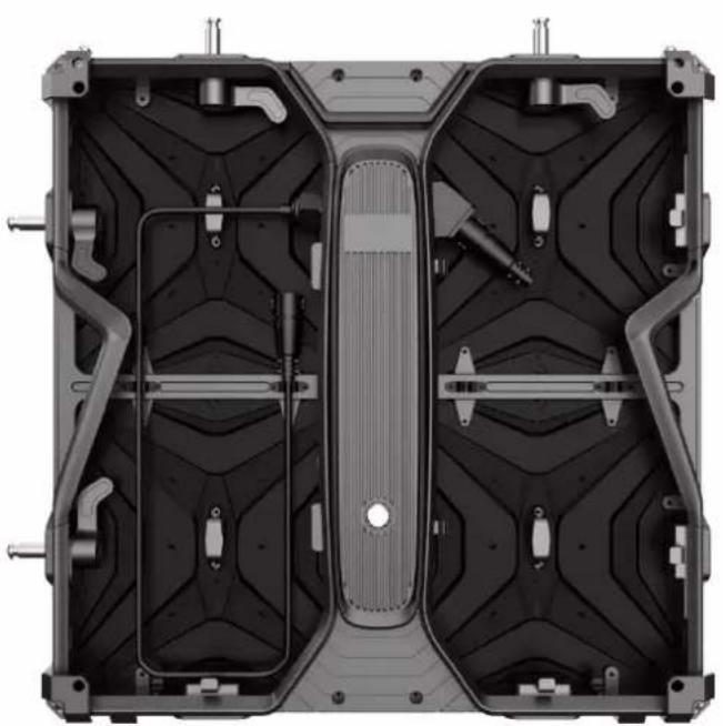
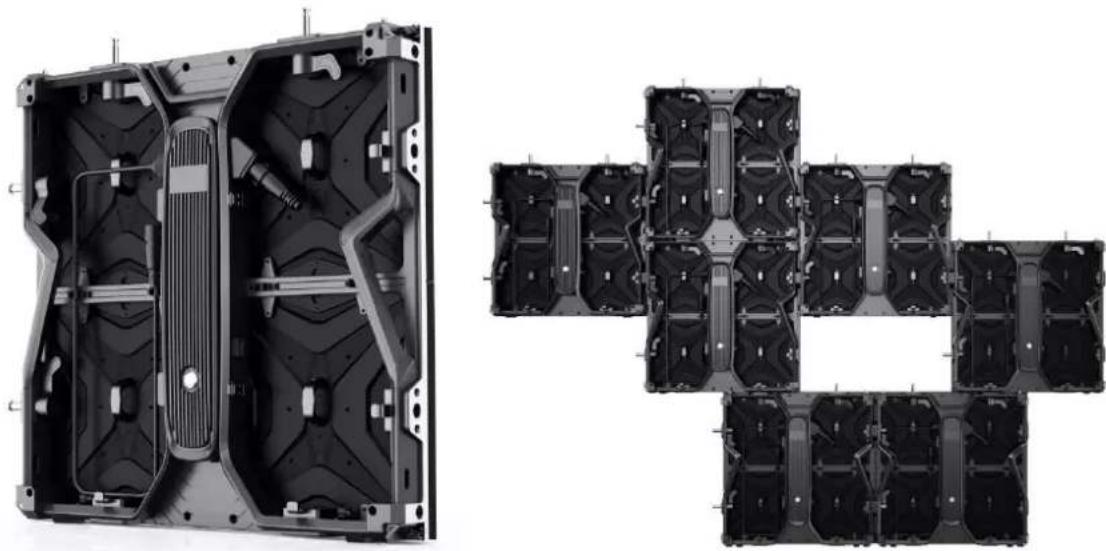
Two technical diagrams showing internal components of a device frame and a separate panel (no text or symbols present)Rear and Front Appearance
1.1 Product Features
● Cabinet is die-casting aluminum integrated.
- Modularized design: LED cabinet consists of frame, power box and modules. For different pixel pitches, they can share same power box and frame.
- Seamless connection: There are four locks totally on each cabinet. They can lock cabinets well for seamless splicing.
● One end of the power cables between two cabinets is fixed. Such design can help to realize fast installation and disassembly.
● Labor saving: One single person can manage installation easily, which can save labor cost.
- Screen can be both inward and outward curve.(needs customization)
- 90° connection is available(needs customization)
- Anti-collision design: there are protectors at the four corners of the cabinets, which can help to protect lamps effectively during transportation (needs customization).
- Multi-application scenarios: It is widely used in concerts, events, opera houses, theaters, hotels, auditorium, multi-function hall, lecture hall, high-end entertainment venues, and so forth.
1.2 Cabinet Demonstration

1.3 Technical Specifications
| App Parameter | Indoor | Outdoor | |||||
| Pixel pitch | 1.95 | 2.6 | 2.97 | 3.91 | 2.97 | 3.91 | 4.81 |
| LED Type | SMD | ||||||
| Pixels Density(Pixel/ m^2 ) | 262144 | 147456 | 112896 | 65536 | 112896 | 65536 | 43264 |
| Module Resolution | 128*128 | 96*96 | 84*84 | 64*64 | 84*84 | 64*64 | 52*52 |
| Cabinet Resolution | 256*256 | 192*192 | 168*168 | 128*128 | 168*168 | 128*128 | 104*104 |
| Module Size (mm) | 250*250 | ||||||
| Cabinet Size (mm) | 500*500 | ||||||
| Cabinet Weight (kg) | 6.8 | 7.3 | |||||
| Brightness ( cd/m^2 ) | ≥800cd/ m^2 | ≥4500cd/ m^2 | |||||
| Viewing Angle (H/V) | 160°/ 140° | ||||||
| Refresh Rate (Hz) | 3840 | ||||||
| Max. Power Consumption ( W/m^2 ) | 600w/ m^2 | 700w/ m^2 | |||||
| Avg. Power Consumption ( W/m^2 ) | 200w/ m^2 | 240w/ m^2 | |||||

natural_image
Cross-sectional view of a car body panel showing internal compartments and structural elements (no text or symbols visible)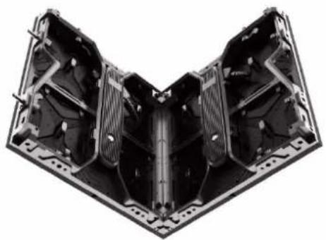
natural_image
3D rendering of a mechanical assembly with internal components (no text or symbols visible)1. 500x500mm(W\*H) 2. 90°Corner connection
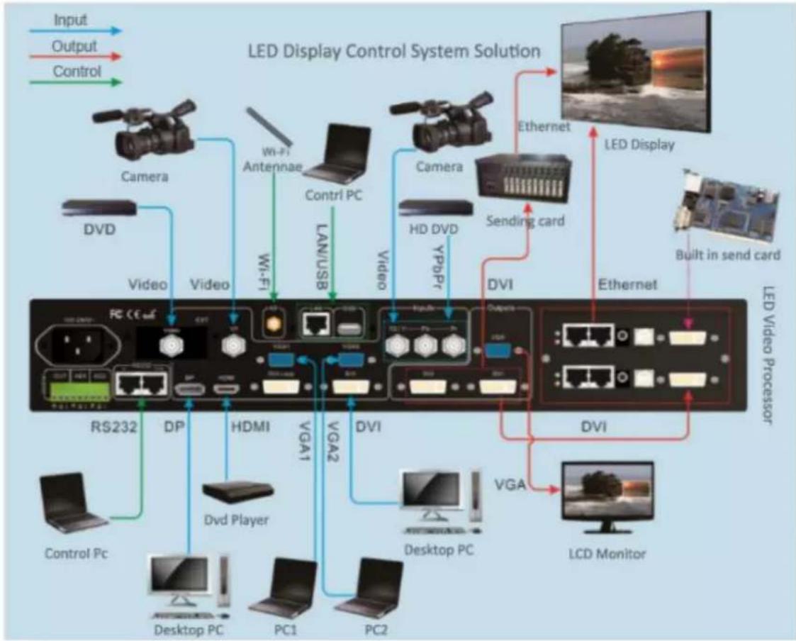
1.4 LED Display Control System Solution
The display system mainly consists of LED screen, control system, control computer, splicing controller, power distribution, other front-end video source and so on.
The system topology is as follows:
flowchart
graph TD
    A["Input"] --> B["LED Display Control System Solution"]
    C["Output"] --> B
    D["Control"] --> B
    B --> E["Camera"]
    B --> F["Video"]
    B --> G["HD DVD"]
    B --> H["DVI"]
    B --> I["DVI"]
    B --> J["LCD Monitor"]
    E --> K["Camera"]
    F --> L["Video"]
    G --> M["HD DVD"]
    H --> N["DVI"]
    I --> O["LCD Monitor"]
    J --> P["LED Display"]
    K --> Q["Wi-Fi Antenna"]
    L --> R["Wi-Fi"]
    M --> S["LAN/USB"]
    N --> T["Video"]
    O --> U["Video"]
    P --> V["LED Video Processor"]
    Q --> W["RS232"]
    R --> X["HPDA"]
    S --> Y["HDMI"]
    T --> Z["VGA1"]
    U --> AA["VGA2"]
    V --> AB["Desktop PC"]
    W --> AC["PC1"]
    X --> AD["PC2"]
    Y --> AE["Control Pc"]
HikVision CBF&CB SERIES LED Video Walls:
natural_image
Technical illustration of a multi-layered automotive chassis with internal components (no text or symbols)1.5 Application Scenarios
LED displays are widely used in meeting rooms, staging events, conference hall, multi-functional studios, airports, stations, urban railways and other public places, as well as hotel lobbies, company exhibition halls, shopping malls, brand stores, promotional sites and home theaters and other fields.
1.5.1 Conference Hall – Staging Events
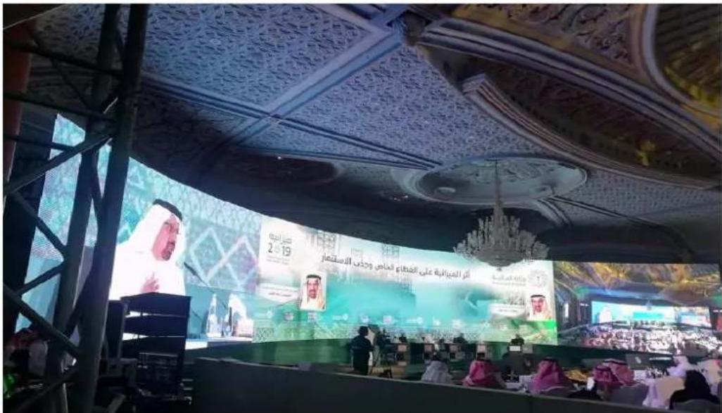
natural_image
Interior of a Turkish television studio with a host at the podium, large screen displaying Turkey’s flag, and audience in red shirts (no readable text or symbols)Chapter 2 Installation and Wiring Demonstration
2.1 For Front Installation Method:
| 2.1.1 Front Installation Demonstration | 2.1.2 Connection Alignment Plates (4-M6 Nuts) |
 |  |
| 2.1.3 Front Mounting Screws (M6*30) | |
 |
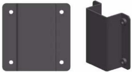
2.2 For Rear Installation Method:
| 2.2.1 Rear Installation Demonstration | 2.2.2 Connection Alignment Plates | |
 | 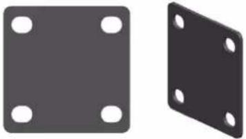 | |
| 2.2.3 Rear Mounting Screws (M10*50) | ||
 | ||
2.3 Stacking Installation Method
2.3.1 Stacking Rear View Demonstration
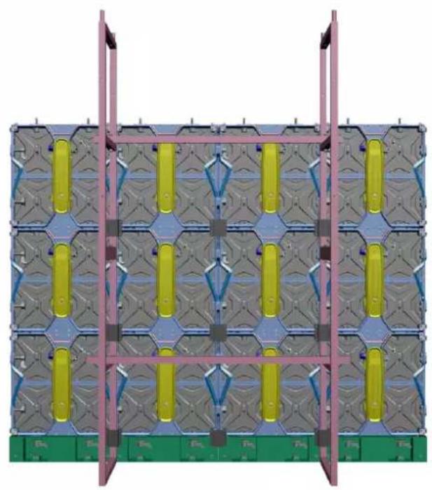
natural_image
3D architectural rendering of a modular building facade with green base and yellow vertical panels, no visible text or symbols2.3.2 Stacking Side View
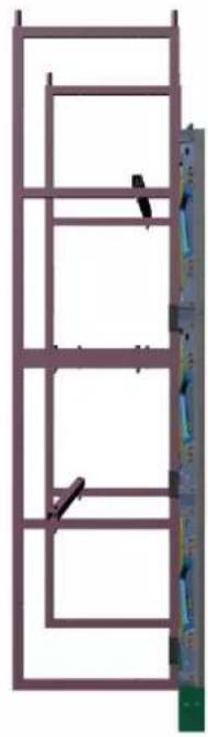
natural_image
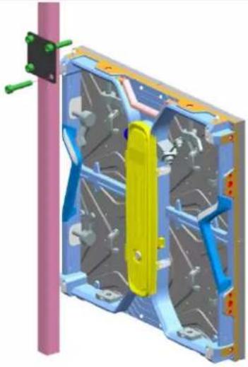
Structural frame with vertical supports and a vertical wall-mounted panel (no text or symbols)2.4 Hanging Installation Method
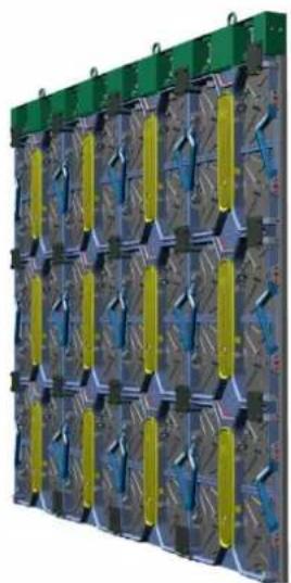
2.4.1 Hanging Rear View Demonstration

natural_image
3D schematic of a modular electronic device with grid patterns and yellow connectors (no text or symbols)2.4.2 Hanging Side View
natural_image
3D rendering of a modular battery pack with green and yellow connectors (no text or symbols visible)2.5 Data and Power Connection
LED display power cable is the cable connecting power distributor and LED screen. GB/CE/UK/UL standard 3*2.5 or 3*4 Sqmm cable is usually used. GB/CE/UK/UL 3*2.5 Sqmm cable loading capacity is not more than 4.5KW. GB 3*4 sqmm cable loading capacity is not more than 6KW. Please note to make wiring in accordance with the standard. Conventional method is horizontal cabling but there are some special situations who can choose only vertical wiring.
In three-phase and five-wire power supply mode, the load of each phase must be evenly distributed to achieve three-phase balance.
LED display data cables include HDMI, DVI and CVBS cables from signal source to processor, HDMI and DVI cables from processor to sending card, USB cable from computer to sending card, and network cable between sending card and receiving card.
Here we mainly talk about the network cable wiring between the sending card and the receiving card. The loading of a network cable cannot exceed 655360 Pixels, and it is a rectangular loading and snake connection wiring. In addition, the load of the sending card or video controller also has the limitation of width, height and total load, which must be considered comprehensively to avoid wiring errors.
Below are the sample about the power wiring and data wiring connection demonstration:
| 2.5.1 data Cable Routing | 2.5.2 Power Cable Routing |
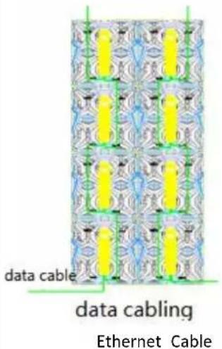 |  Main Power Cable Connection Main Power Cable Connection |

text_image
power cable data cableChapter 3: LED Display Configuring and Debugging
3.1 Configuring Preparation
3.1.1 Ensure that power cables and data cables are correctly routed before powering up the screen and equipment.
3.1.2 Start the control computer, start the Windows system, and set the computer graphics card to duplicate mode after the graphics card driver is finished. Short cut key is "Windows key" + "P" to select "Duplicate mode".

text_image
PC screen only Duplicate Extended Second screen only3.1.3 Software Installation
Software Download Link: https://www.novastar-led.cn/index/downloadcenter/index.html?type=software
Download display debugging software(Nova LCT) and PC player software(ViPlex Express).
3.2 LED Display Configuring
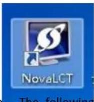
text_image
NovaLCT The followingDouble-click to open, The following window is displayed:

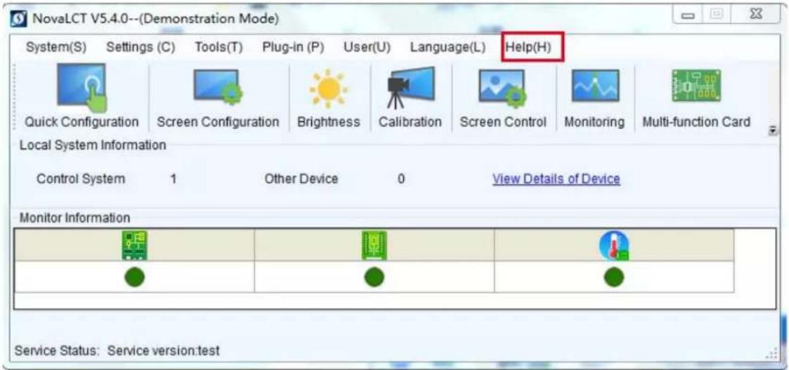
text_image
NovaLCT V5.4.0--(Demonstration Mode) System(S) Settings (C) Tools(T) Plug-in (P) User(U) Language(L) Help(H) Quick Configuration Screen Configuration Brightness Calibration Screen Control Monitoring Multi-function Card Local System Information Control System 1 Other Device 0 View Details of Device Monitor Information Service Status: Service version:testThe control system displays 1, indicating that the USB cable is connected normally.
text_image
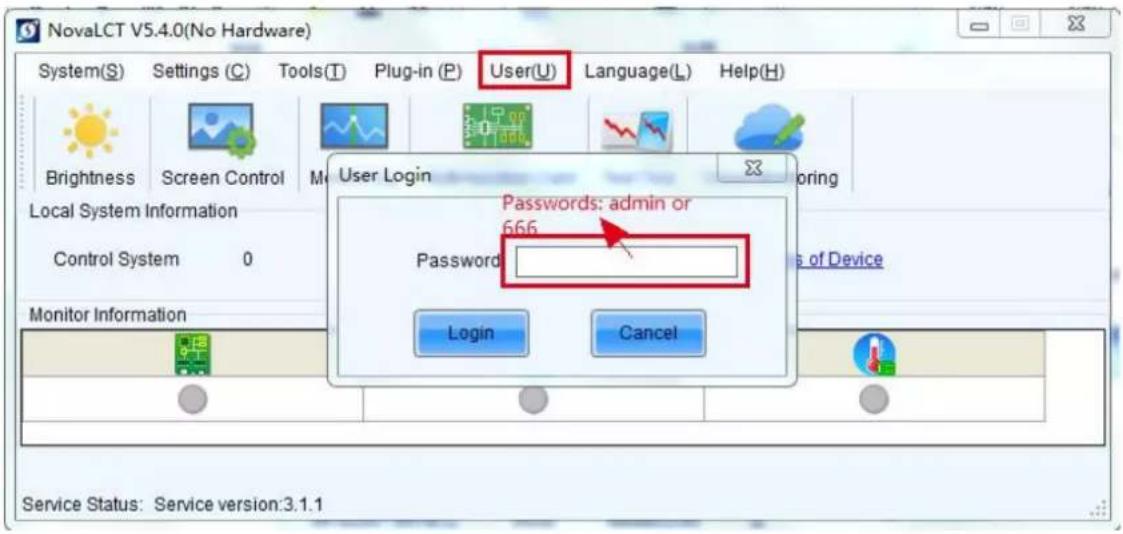
NovaLCT V5.4.0(No Hardware) System(S) Settings (C) Tools(T) Plug-in (P) User(U) Language(L) Help(H) Brightness Screen Control User Login Local System Information Control System 0 Monitor Information Login Cancel Passwords: admin or 666 Password Service Status: Service version:3.1.1Password: 666 or admin
text_image
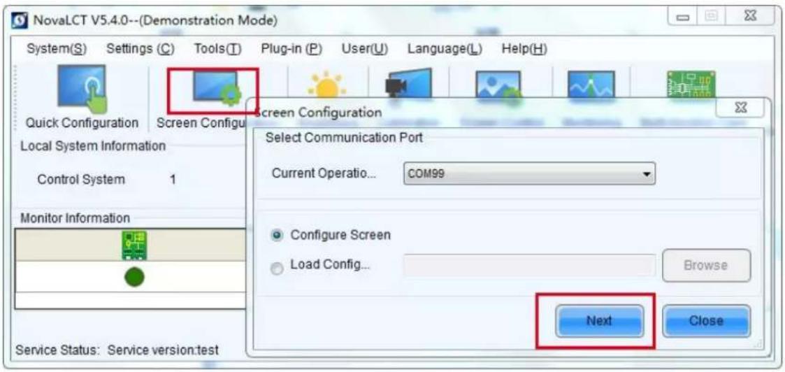
NovaLCT V5.4.0--(Demonstration Mode) System(S) Settings (C) Tools(T) Plug-in (P) User(U) Language(L) Help(H) Quick Configuration Screen Configur Local System Information Control System 1 Monitor Information Service Status: Service version:test Screen Configuration Select Communication Port Current Operation... COM99 Configure Screen Load Config... Browse Next Close3.2.1 Sending Card Settings

text_image
Screen Configuration-COM99 Sending Card Receiving Card Screen Connection Display Mode Refresh Current Display Mode Sending Card ... ??? Graphics Output R... 1366 x 768 Curre... ???? Select Input Source Video Input Automati... HDMI Send 3D Function Enable Settings Source Configuration Source: HDMI Resolution: 1440 x 900 px Custom... 1366 x 768 Refresh Rate T... 60 Hz Input Source Bit De... 8 Bit Set Hot Backup Verification Verify Redundancy Set the Current Devi... Set as Primary Set as Backup Primary Backup Serial Number of Primary Sending Card Serial Number of Primary Port Serial Number of Backup Sending Card Serial Number of Backup Port Refresh Send Add Edit Delete Restore Factor... Save System Co... Save CloseSending card interface: For LED display with 1920*1080 resolution or lower, ensure that the sending card resolution is consistent with the display card output resolution and the sending card resolution is greater than or equal to the LED display resolution; If the resolution exceeds 1920*1080, you can customize the resolution.
3.2.2 Receiving card Settings
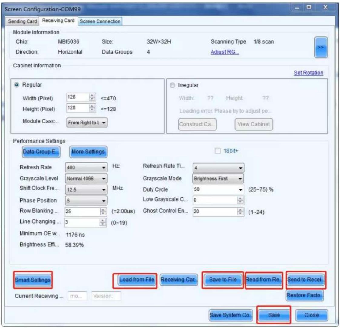
text_image
Screen Configuration-COM99 Sending Card Receiving Card Screen Connection Module Information Chip: MBI5036 Size: 32W×32H Scanning Type 1/8 scan Direction: Horizontal Data Groups 4 Adjust RG... Cabinet Information Set Rotation Regular Width (Pixel) 128 <=470 Height (Pixel) 128 <=128 Module Casc... From Right to I Irregular Width: ? Height ? Loading error. Please try to adjust pe... Construct Ca... View Cabinet Performance Settings Data Group E More Settings 18bit+ Refresh Rate 480 Hz Refresh Rate Ti... 4 Grayscale Level Normal 4096 Grayscale Mode Brightness First Shift Clock Fre... 12.5 MHz Duty Cycle 50 (25~75) % Phase Position 5 Low Grayscale C... 0 Row Blanking ... 25 (=2.00us) Ghost Control En... 20 (1~24) Line Changing ... 3 (0~19) Minimum OE w... 1176 ns Brightness Effi... 58.39% Smart Settings Load from File Receiving Car... Save to File Read from Re.Send to Recei... Current Receiving ... mo... Viklon. Save System Co... Save Close- For the cabinet containing the receiving card, after the connection is normal, the LED screen will display a normal picture, but not a complete picture. In this case, it is recommended to read from the receiving card and save it to a file for backup, so as to avoid the incorrect operation of later staff to find the correct configuration file (.RCFGX).
- For the LED screen without receiving card, the basic can be set intelligently according to the module information; Non-professional, you can find the manufacturer to get the correct RCFGX file, load it from the file, then send it to the receiving card, and finally solidify.
3.3 Screen Connection

text_image
Screen Configuration-COM99 Sending Card Receiving Card Screen Connection Screen1 Screen Type: Standard Screen Complex Screen Sending Card Number 1 2 3 4 5 1 2 3 4 5 Ethernet Port No. 1 2 3 4 5 6 7 8 9 10 11 12 13 14 15 16 Receiving Card Size Width: 128 Height: 128 Apply to Enter... Apply to Enter... Set Blank Apply to the current... Quick Connection 3 Select Communic....Read the Number Restore Factor Quantity 0... 1 Configur Basic Information Coordinate: X: 0 Y: 0 Virtual Mo... E... Enabl... Screen Ar... 1366 x 750 Columns 4 Row 2 ResetAll Hided ... Red 4 Sending Card:1 Port:1 Receiving Card:4 Width:128 Sending Card:1 Port:1 Receiving Card:3 Width:128 Sending Card:1 Port:1 Receiving Card:2 Width:128 Sending Card:1 Port:1 Receiving Card:1 Width:128 Sending Card:1 Port:1 Receiving Card:5 Width:128 Sending Card:1 Port:1 Receiving Card:6 Width:128 Sending Card:1 Port:1 Receiving Card:7 Width:128 Sending Card:1 Port:1 Receiving Card:6 Width:128 Enable Mapping Load from File Save to File Read from HW Send to HW Save System Co... Save CloseAccording to the previous network cable wiring, configure the display screen, change the number of receiving card columns, rows, and load width and height of receiving card. For MRV412, MRV416 and AXS series (A5s, A8s, etc.) receiving cards, you can open the Mapping function, see the cable routing mode, and then click the corresponding grid (grid is the front view), and then send to the hardware (Send to HW), solidification (Save). Finally, it can be saved to a file to avoid the loss of screen connection files by mis-operation.
After the connection, the screen displays into a complete picture. Well done!!
For more instructions, see the main menu interface help - User Files.
text_image
NovaLCT V5.4.0--(Demonstration Mode) System(S) Settings (C) Tools(T) Plug-in (P) User(U) Language(L) Help(H) Quick Configuration Screen Configuration Brightness Calibration Screen Control Monitoring Multi-function Card Local System Information Control System 1 Other Device 0 View Details of Device Monitor Information Service Status: Service version:test3.4 Broadcasting a video or program!

Double-click to open The following window is displayed:
text_image
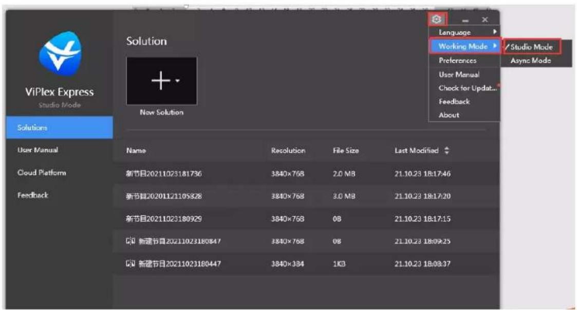
ViPlex Express Studio Mode Solution New Solution Language Working Mode Preferences User Manual Check for Update... Feedback About Studio Mode Async Mode Solutions User Manual Cloud Platform Feedback Name Resolution File Size Last Modified 新节目20211023181736 3840×768 2.0 MB 21.10.23 18:17:46 新节目202011/21105828 3840×768 3.0 MB 21.10.23 18:17:20 新节目20211023180929 3840×768 0B 21.10.23 18:17:15 新建节目20211023180847 3840×768 0B 21.10.23 18:09:25 新建节目20211023180447 3840×384 1KB 21.10.23 18:08:37Click Setting-Working mode, and choose local play (synchronous mode, connected to the computer for play) or asynchronous play (offline play).
Here we will briefly explain local play.
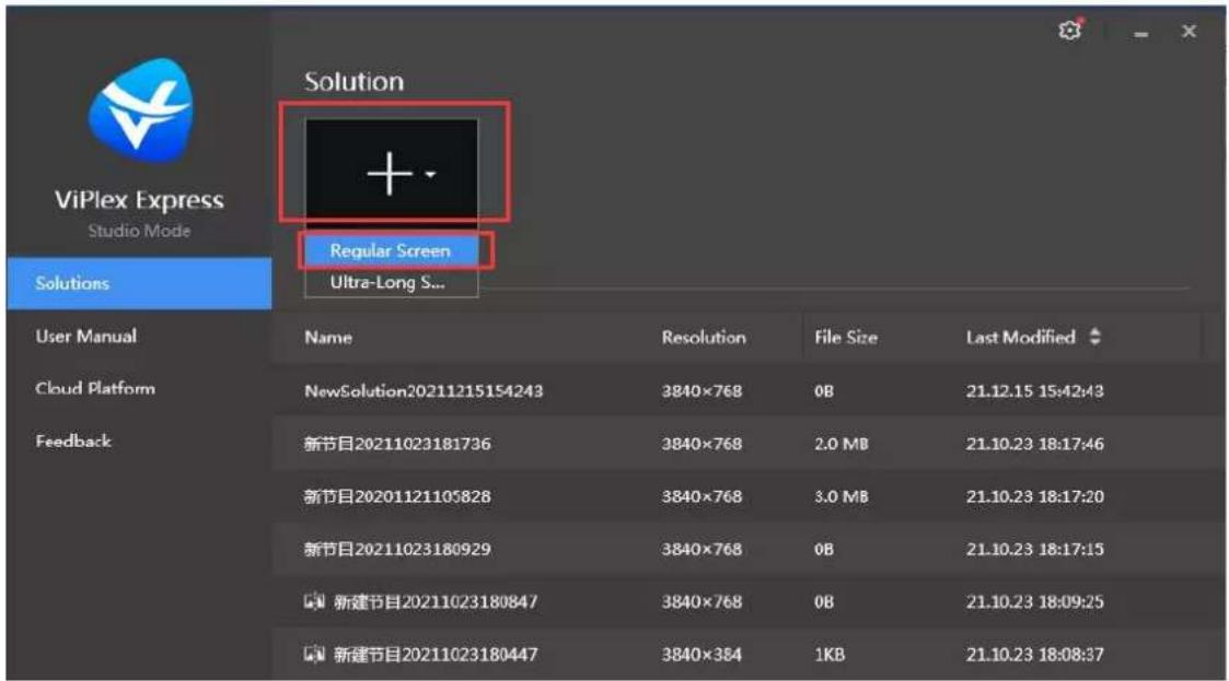
Click "1" to new solution, select regular screen.
text_image
ViPlex Express Studio Mode Solution + - Regular Screen Ultra-Long S... Solutions User Manual Name Resolution File Size Last Modified Cloud Platform NewSolution20211215154243 3840×768 0B 21.12.15 15:42:43 Feedback 新节目20211023181736 3840×768 2.0 MB 21.10.23 18:17:46 新节目20201121105828 3840×768 3.0 MB 21.10.23 18:17:20 新节目20211023180929 3840×768 0B 21.10.23 18:17:15 新建节目20211023180847 3840×768 0B 21.10.23 18:09:25 新建节目20211023180447 3840×384 1KB 21.10.23 18:08:37Set the size and starting position of the playback window according to the size of the LED display.
text_image
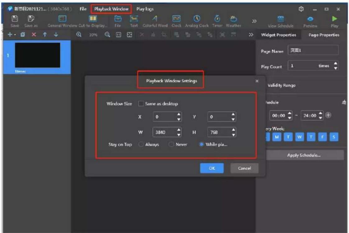
新节目2021121... (3840x768) File Playback Window Play logs Save Save as General Window Cut to Display... File Text Colorful Word Clock Analog Clock Timer Weather > View Schedule Preview Play 10% Timer Widget Properties Page Properties Page Name 页面1 Play Count 1 times Playback Window Settings Window Size Same as desktop X 0 Y 0 W 3840 H 768 Stay on Top Always Never While pla... OK Cancel Validity Range Schedule 00:00 - 24:00 + Every Week M T W T F S Apply Schedule...Select general window, file, add file, display as follows:
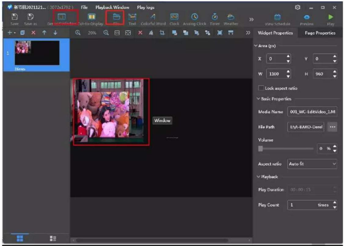
text_image
新节目2021121... (3072x1792) File Playback Window Play logs Save Save as Get and Window Cut-to-Display File Text Colorful Word Clock Analog Clock Timer Weather View Schedule Previous Play 20% 20% 20% 20% 20% 20% 20% 20% 20% 20% 20% 20% 20% 20% 20% 20% 20% 20% 20% 20% 20% 20% 20% 20% 20% 20% Widget Properties Page Properties Area (px) X 0 Y 0 W 1100 H 960 Lock aspect ratio Basic Properties Media Name 001_WC-EditVideo_1.M File Path EAA-EAKO-Derel ... Volume 0 % Aspect ratio Auto fit Playback Play Duration 00:00:15 Play Count 1 timesClick component properties on the right to unlock aspect ratio, change starting position and width.

text_image
新节目2021121... (3072x1792) File Playback Window Play logs Save Save as General Window Cut-to-Display File Text Colorful Word Clock Analog Clock Times Weather 20% View Schedule Previous May Widget Properties Page Properties Area (px) X 0 Y 0 W 1100 H 960 Lock aspect ratio Basic Properties Media Name 001_WC-EditVideo_1.M File Path E:\A-BAKO-Derel ... Volume 0 % Aspect ratio Auto fit Playback Play Duration 00:00:15 Play Count 1 timesClick page properties to set the schedule as required.
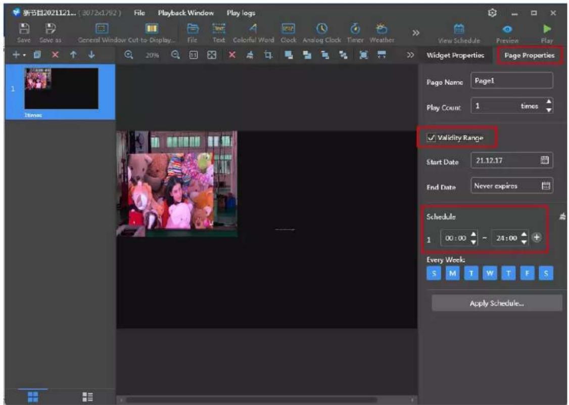
text_image
新节目2021121... (3072x1792) File Playback Window Play logs Save Save as General Window Cut to Display File Text Colorful Word Clock Analog Clock Timer Weather View Schedule Preview Play Widget Properties Page Properties Page Name Page1 Play Count 1 times ✓ Validity Range Start Date 21.12.17 End Date Never expires Schedule 1 00:00 ~ 24:00 + Every Week: S M T W T F S Apply Schedule...Click Play then it is done:
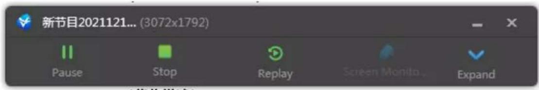
text_image
新节目2021121... (3072x1792) Pause Stop Replay Screen Monitor... ExpandClick expand to edit again.
More operation instructions can be viewed by clicking the software user manual:

text_image
ViPlex Express Studio Mode Solutions User Manual Name Resolution File Size Last Modified NewSolution20211215154442 3840×768 0B 21.12.15 15:44:42 NewSolution20211215154243 3840×768 0B 21.12.15 15:42:43 新节目20211023181736 3840×768 2.0 MB 21.10.23 18:17:46 新节目20201121105826 3840×768 3.0 MB 21.10.23 18:17:20 新节目20211023180929 3840×768 0B 21.10.23 18:17:15Chapter 4. Cabinet Maintenance and Operating Service
4.1 Remove the power supply
4.1.1 Power off!! Loosen two buckles on the rig
4.1.2 Open the power box cover

Danger

natural_image
Top-down view of a vehicle chassis with visible structural components and blue connectors (no text or symbols)
natural_image
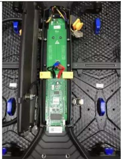
Interior view of an electronic device with visible circuit board, connectors, and wiring (no text or symbols)4.1.3 Remove the screws from the power terminal and disconnect the power cable
4.1.4 Remove the four retaining screws on the power board and remove the power supply

natural_image
Top-down view of an electronic vehicle chassis with visible circuit board, battery pack, and wiring (no text or symbols)
natural_image
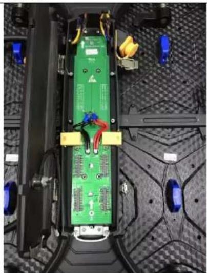
Interior view of a vehicle chassis with visible electronic components and wiring (no text or symbols)4.2 Remove receiving card
4.2.1 Pull out the button terminal and remove the receiving card fixing screw
natural_image
Top-down view of an electronic vehicle chassis with visible circuit board and wiring (no text or symbols)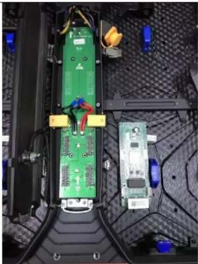
natural_image
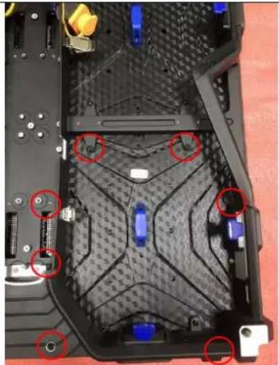
Interior view of a laptop chassis showing green circuit board and adjacent circuit board with wiring (no visible text or symbols)4.3 Remove adapter plate (Also called HUB).
4.3.1 Remove the three adapters plate retainin screws
natural_image
Top-down view of a green electronic circuit board with visible wiring and components, placed on a textured mechanical surface (no text or symbols)
natural_image
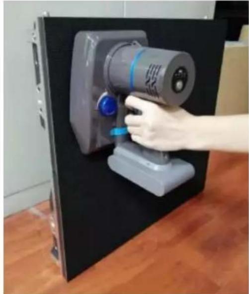
Interior view of a vehicle chassis with visible wiring, sensors, and electronic components (no text or symbols)4.4 Remove the modules
Indoor: use module remover to take it out
natural_image
Hand operating a gray industrial vacuum cleaner device mounted on a black base, with wooden flooring visible (no text or symbols)Outdoor:
4.4.1 Remove the 7pcs module retaining screw | 4.4.2 Take out the module
natural_image
Top-down view of a laptop's rear panel showing internal components and mounting points (no text or symbols visible)
natural_image
Top-down view of a red automotive chassis with visible components and mounting hardware (no text or symbols)4.5 Other Important Tips for Moisture Protection
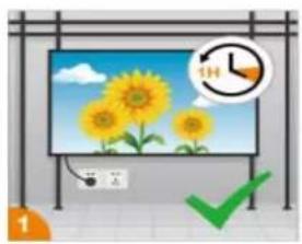
a) The daily running time of the LED Screen should be more than 1 hour (video can be played if there is no need for use);
b) Avoid air conditioner blowing directly on the screen, ensure that the ambient humidity of the screen is controlled at 70%.
c) Do not allow the LED Display beads to come into contact with water or wet rag.
d) Avoid touching the display beads directly with your hands or with items that can generate strong static electricity. (e.g., nylon, wool sweaters, etc.)
natural_image
Illustration of a solar TV with sunflowers and a clock showing 1 hour (no text or symbols on screen)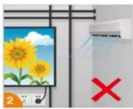
natural_image
Illustration of a solar panel with sunflowers and a whiteboard, next to a red X symbol (no text or labels)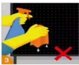
text_image
Illustration showing hands cleaning a surface with a spray bottle and a red X mark, likely indicating anti-smoking or disinfection.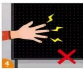
text_image
Illustration showing a hand touching a grid with lightning bolts and a red X symbol, likely indicating electric shock or hazard.(e) It's prohibited to use 84 disinfectant containing (Fluorine, Bromine) or highly effective disinfectant water to spray directly on the environment where the display is used. If disinfection is required, it's recommended that 75% medical alcohol be used and the power to the display must be turned off during disinfection. Prohibit flames, prevent static electricity, maintain ventilation and pay attention to safety.
(f) If the display has not been used for a long time (two use time not more than 5 days), be sure to dehumidify before use, using a gradual increase in brightness, slow warming to remove the accumulated moisture in the unused period of the product, specific operation methods are as follows:
| No. | Time (H) | Dehumidification Steps |
| 1 | At 0-2 hours | leave the screen in a black state to warm up |
| 2 | At 2-4 hours | Level 30 grayscale aging |
| 3 | At 4-6 hours | Level 60 grayscale aging |
| 4 | At 6-9 hours | Level 90 grayscale aging |
| 5 | At 9-12 hours | Level 150 grayscale aging |
PS: Reduce or extend the aging time according to the actual usage environment, climate and shutdown time.
Chapter 5. Packages Details
5.1 Flight Cases Packing
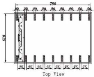
text_image
780 610 75. 25. 25. 25. 25. 25. 25. 25. 25. Top View500x500mm (Standard type) - Standard flight case
Cabinet size: 500x500x71mm
Inner size of flight case: 780x510x540mm (8in1)
Cabinet body color: Black(Aluminum alloy frame: natural color).
Thickness of fireproof sheet: 9mm
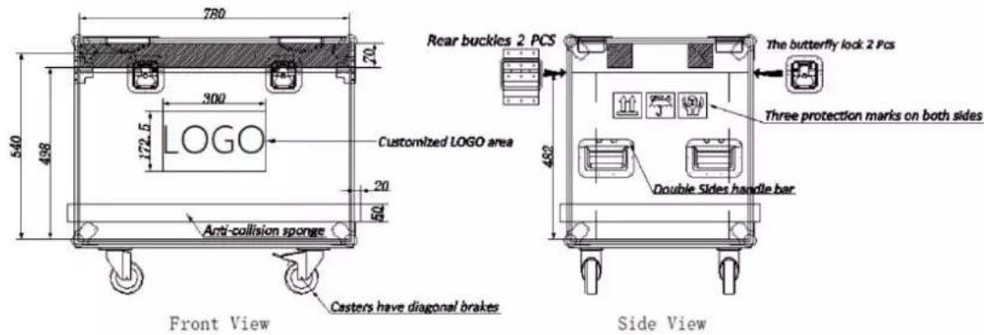
text_image
780 70 540 498 300 172.5 LOGO Customized LOGO area 20 50 Anti-collision sponge Front View Casters have diagonal brakes Rear buckles 2 PCS The butterfly lock 2 Pcs Three protection marks on both sides Double Sides handle bar Side View5.2 wooden box Packing

natural_image
Wooden box containing multiple black components on a green surface, no visible text or symbols
text_image
HIKVISION HIKVISION
See Far, Go Further