ZUMLINK-US-HALLWAY-DLS-RLY - Motion detector Crestron - Free user manual and instructions
Find the device manual for free ZUMLINK-US-HALLWAY-DLS-RLY Crestron in PDF.

User questions about ZUMLINK-US-HALLWAY-DLS-RLY Crestron
0 question about this device. Answer the ones you know or ask your own.
Ask a new question about this device
Download the instructions for your Motion detector in PDF format for free! Find your manual ZUMLINK-US-HALLWAY-DLS-RLY - Crestron and take your electronic device back in hand. On this page are published all the documents necessary for the use of your device. ZUMLINK-US-HALLWAY-DLS-RLY by Crestron.
USER MANUAL ZUMLINK-US-HALLWAY-DLS-RLY Crestron
Crestron Zūm® Wired Lighting Control
Product Manual
Crestron Electronics, Inc.
Original Instructions
The U.S. English version of this document is the original instructions.
All other languages are a translation of the original instructions.
Regulatory Model: M201903003
This product may be purchased from select authorized Crestron dealers and distributors. To find a dealer or distributor, please contact the Crestron sales representative for your area. A list of sales representatives is available online at www.crestron.com/How-To-Buy/Find-a-Representative or by calling 855-263-8754.
Crestron product development software is licensed to Crestron dealers and Crestron Service Providers (CSPs) under a limited nonexclusive, nontransferable Software Development Tools License Agreement. Crestron product operating system software is licensed to Crestron dealers, CSPs, and end-users under a separate End-User License Agreement.
Both of these Agreements can be found on the Crestron website at www.crestron.com/legal/software_license_agreement.
The product warranty can be found at www.crestron.com/warranty.
The specific patents that cover Crestron products are listed online at www.crestron.com/legal/patents.
Certain Crestron products contain open source software. For specific information, please visit www.crestron.com/opensource.
Crestron, the Crestron logo, 4-Series, Cresnet, XiO Cloud, Crestron Toolbox, SIMPL+, and Züm are either trademarks or registered trademarks of Crestron Electronics, Inc. in the United States and/or other countries. BACnet is either a trademark or registered trademark of American Society of Heating, Refrigerating and Air-Conditioning Engineers, Inc. in the United States and/or other countries. Apple and iOS are either trademarks or registered trademarks of Apple Inc. in the United States and/or other countries. Bluetooth is either a trademark or registered trademark of Bluetooth SIG, Inc. in the United states and/or other countries. Android and Google Play are either trademarks or registered trademarks of Google Inc. in the United States and/or other countries. DALI is either a trademark or registered trademark of Digital Illumination Interface Alliance in the United States and/or other countries. Active Directory is either a trademark or registered trademark of Microsoft Corporation in the United States and/or other countries. STEINEL is either a trademark or registered trademark of Steinel Vertrieb GmbH in the United States and/or other countries. UL is either a trademark or registered trademark of UL LLC in the United States and/or other countries. Wi-Fi is either a trademark or registered trademark of Wi-Fi Alliance in the United States and/or other countries. Other trademarks, registered trademarks, and trade names may be used in this document to refer to either the entities claiming the marks and names or their products. Crestron disclaims any proprietary interest in the marks and names of others. Crestron is not responsible for errors in typography or photography.
©2023 Crestron Electronics, Inc.
Contents
Overview 8
Load Controllers..8.
Keypad 10
Presence Detectors 10
Hub .12
Software 13
Zūm App 13
Custom Program License for the ZUM-HUB4 13
Accessories 14.
Cables 14
Adapter Cable 15
RJ-45 Splitter 15
Zūm Link Power Supply 16
Rocker Button and Button Trees 16
Features 17
Load Controller Features 18
Keypad Features 26
Presence Detector Features 28
Hub Features 30
Software Features 34
Cable Features 35
Cable Accessory Features 36
Power Supply Features 37
Rocker and Button Tree Features 38
Application Scenarios 40
Specifications
Load Controller Specifications 43
ZUMNET-JBOX-16A-LV Product Specifications 43
ZUMNET-JBOX-16A-LV Dimension Drawings 45
ZUMNET-JBOX-DALI Specifications 45
ZUMNET-JBOX-DALI Dimension Drawings 48
ZUMLINK-JBOX-16A-LV Specifications 48
ZUMLINK-JBOX-16A-LV Dimension Drawings 51
ZUMLINK-JBOX-20A-PLUG Specifications 51
ZUMLINK-JBOX-20A-PLUG Dimension Drawings 54
ZUMLINK-JBOX-20A-SW Specifications 54
ZUMLINK-JBOX-20A-SW Dimension Drawings 57
ZUMLINK-EXP-16A-DIMU Specifications 57
ZUMLINK-EXP-16A-DIMU Dimension Drawings 60
Keypad Specifications 61
Product Specifications 61
Dimension Drawings 62
Presence Detector Specifications 63
Product Specifications 63
Dimension Drawings 67
Hub Specifications 73
ZUM-HUB4 Specifications 73
ZUM-HUB4 Dimension Drawings.75
ZUML-HUB4-GW Specifications 76
ZUML-HUB4-GW Dimension Drawings 77
ZUML-HUB4-PAK Specifications 77
ZUML-HUB4-PAK Dimension Drawings.79
ZUML-HUB4-CN-PAK Specifications 79
ZUML-HUB4-CN-PAK Dimension Drawings 81
Zūm App Specifications 83
Cable Specifications
CBL-CAT5E-ZUMNET-P Specifications
CBL-CAT5E-ZUMNET-P Dimension Drawings
CBL-CAT5E-ZUMLINK-P Specifications
CBL-CAT5E-ZUMLINK-P Dimension Drawings
Cable Accessory Specifications
ZUMLINK-CONV-CN Product Specifications
ZUMLINK-CONV-CN Dimension Drawings
ZUMLINK-SPLTR-RJ45 Product Specifications
ZUMLINK-SPLTR-RJ45 Dimension Drawings
Power Supply Specifications
Product Specifications
Dimension Drawings
Rocker and Button Tree Specifications 92
Product Specifications 92
Dimension Drawings 93
Installation 94
Load Controller Installation 95
In the Box 95
Install the Load Controller 96
Test the Loads 102
Universal Dimmer Load Controller Installation 104
In the Box 104
Important Safeguards 104
Install the Universal Dimmer Load Controller 105
Wiring the Universal Dimmer Load Controller 106
Keypad Installation 109
In the Box 109
Install the Keypad 109
Wire the Keypad 111
Mount the Keypad 112
Replace the Rocker Button/Button Tree and Bezel 114.
Presence Detectors Installation 116
In the Box 117
Remove or Attach the Backplate 118
Junction Box Mounting 118
Ceiling Mounting 121
Beam Pattern Coverage 125
Hub Installation 132
In the Box 132
Mount to a Rack 132
Place onto a Flat Surface 133
Make Connections 133
Cable Accessory Installation 136
In the Box 136
ZUMLINK-SPLTR-RJ45 Connections 136
ZUMLINK-CONV-CN Connections 137
Applications 138
Power Supply Installation 140
In the Box 140
Install the Power Supply 140
Rocker and Button Tree Installation 145
In the Box 145
Install a Bezel and Rocker Button or Button Tree 145
Operation 147
Load Controller Operation 148
Universal Dimmer Load Controller Operation 152
Set the Dimming Mode 152
Test the Loads 153
Factory Reset 153
Universal Dimmer LEDs 153
Error States 154
Zero-Cross Filter 154
Keypad Operation 155
Presence Detectors Operation 156
Configuration 157
Züm App Configuration 158
Züm App Main Screen 158
Update Firmware with the Zūm App 164
Load Controllers Zūm App Configuration 167
Keypad Zūm App Configuration 214
Presence Detectors Zūm App Configuration 219
Hub Web Interface 229
Web Interface Overview 230
Web Interface Configuration 233
Resources 280
Crestron Support and Training 280
Programmer and Developer Resources 280
Product Certificates 280
Related Documentation 281
Models 282
Load Controllers 282
Keypad 282
Presence Detectors 282
Hub and Kits 283
Software 284
Power Supply 284
Cables 284
Cable Accessories 285
Rocker and Button Trees 285
Overview
Zūm Wired is a distributed lighting control system that uses industry standards, such as 0-10V, DALI ^® , DMX and phase control all merged on an enterprise IoT network, Zūm Net. This network not only provides communication and control of your lighting, but also seamlessly integrates with Crestron ^® Unified Communications systems and third-party occupancy, environmental & acoustical sensors or other data related IoT devices.
All Zūm devices interface with the Zūm app, providing easy set up for all room aspects and parameters including presets, lighting levels and optimized sensor settings. Spaces or rooms can be saved and used as templates for use in other spaces, which greatly reduces the time required to start up your systems.
Load Controllers
Zūm Net and Zūm Link load controllers provide a sophisticated, wired lighting control solution for Zūm® commercial lighting systems.
ZUMNET-JBOX-16A-LV and ZUMNET-JBOX-DALI
Zūm Net devices facilitate communications between rooms via CBL-CAT5E-ZUMNET-P cables (sold separately, refer to Cables on page 14) and can be daisy-chained for network expansion. They also connect to connect to Zūm Link devices for in-room communication. The load controllers mount directly to a 4 in. square junction box.
natural_image
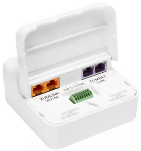
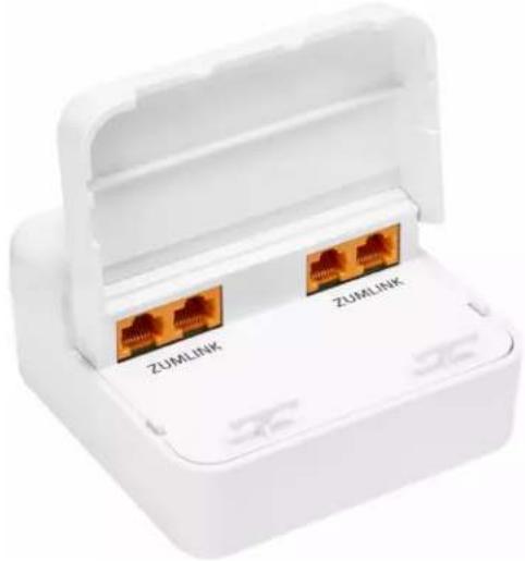
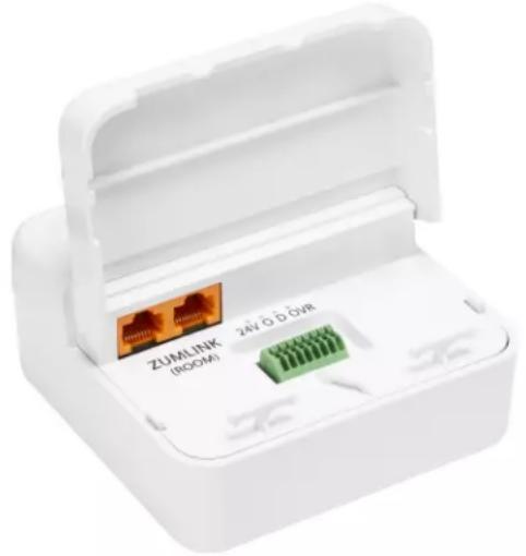
White wireless router adapter with three labeled ports (ZUMLINK ROOM, 24V D/DVR, ZUMNET LAN) and a green connector on the base (no text beyond labels)ZUMLINK-JBOX-16A-LV, ZUMLINK-JBOX-20A-SW, and ZUMLINK-JBOX-20A-PLUG
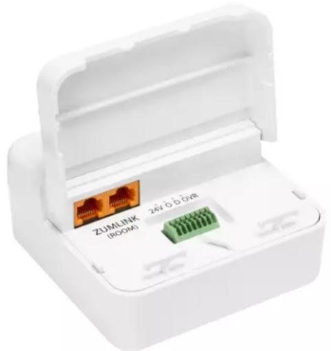
Zūm Link devices allow for in-room lighting control through compatible keypads and sensors. Two RJ-45 ports on the device and the CBL-CAT5E-ZUMLINK-P cables (sold separately refer to Cables on page 14) allow for connection to a Zūm Net device and for in-room device daisy-chaining.
natural_image
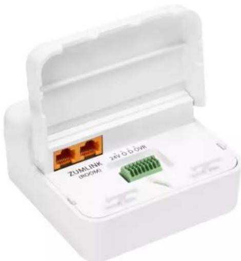
White plastic electronic device with a green connector and two USB port labels (no readable text beyond branding)ZUMLINK-EXP-16A-DIMU
The Crestron Zūm® Wired Lighting Control is a single-channel universal dimmer load controller designed to control a wide range of dimmable lighting load types. Using proprietary zero-cross filter technology, the Crestron Zūm® Wired Lighting Control provides superior immunity to power line noise, resulting in a significant reduction of lamp flicker.
Energy-saving options (sold separately) are available to enable daylighting, occupancy or vacancy sensing, integration, and centralized monitoring and management.
text_image
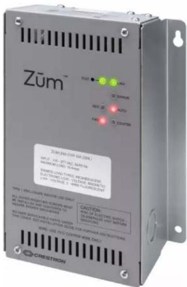
Zūm™ ZUM-PR (20P-15A-20M) INPUT: 100 μΩ, 270 μΩ, 340 μΩ MAX: 100 μΩ, MAX: 100 μΩ MINED: 300 μΩ, MAX: 300 μΩ HENSIC TYPE: MICRO-DIGENER ELECTRONIC TIME: VOLTAGE, MAX: 100 μΩ, CONTROL 2, MAX FLUORENT MINI: 100 μΩ, MAX: 100 μΩ ALL-SURVE WEIGHTS & GOURS WILL NOT BE INSTALLED INJ. SWITCHER TO MAKE FLOWER SWITCHER TO WE ARE SPECIFICATIONS AVAILABLE FOR MORE FOR OTHERS OUT of SWITCHING. THE SAIRS BUT INSTALLATION GUIDE FOR OTHERS OUT OF SWITCHING. CRESTRON CAUTION: MINI OF FLUORENT SWITCHER CHINESE INPUT MAY BEANS SPRING ON WIRE-USB AND COPIER-USB ONLYKeypad
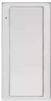
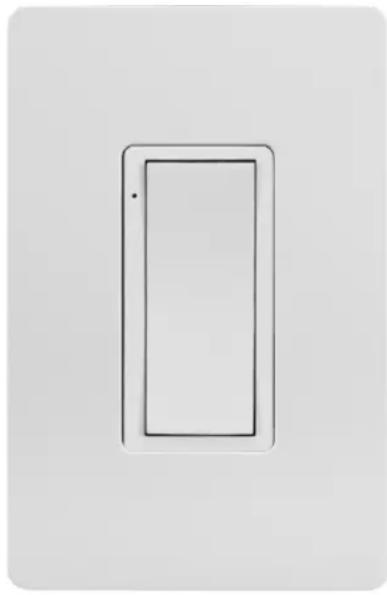
The ZUMLINK-KP keypad provides control of one or more Züm® wired load controllers (sold separately, refer to Load Controllers on page 8) via CBL-CAT5E-ZUMLINK-P cables (sold separately, refer to Cables on page 14). The ZUMLINK-KP comes preassembled with the white ZUMLINK-BTNR rocker button, which offers on/off switching and dimming adjustment with the ability to save one scene preset. Additional pushbutton configurations are available separately. Refer to Rocker and Button Tree Features on page 38 for details. The pushbutton configurations support the same capabilities as the rocker button but with additional scene presets.
The ZUMLINK-KP mounts to a standard electrical box. Rocker buttons/button trees and bezels are available in almond, black, gray, red, and white. The button trees also have options for blank buttons, standard pad printed labels, or custom engravings. A finished installation requires a decorator-style faceplate (FP-G series, sold separately).
natural_image
Simple line drawing of a rectangular frame with no text or symbols(Faceplate not included)
Presence Detectors
STEINEL™ presence detectors with Zūm® Link wired communication are part of a system designed to provide sophisticated lighting control with simple installation. A wired solution for Zūm commercial lighting systems, the presence detectors communicate via
CBL-CAT5E-ZUMLINK-P cable (sold separately, refer to Cables on page 14) which allow for in-room device daisy-chaining to other Zūm Link devices (such as the ZUMLINK-KP keypad or Zūm Link load controllers, refer to Load Controllers on page 8 and Keypad on page 10). The
presence detectors are equipped with a daylight sensor and mount directly to the ceiling or via a junction box (not included). The RLY presence detectors also have a three-wire output relay to connect to a relay-input capable device, such as an HVAC call system.
Presence Detector with Daylight Sensing
• ZUMLINK-IR-QUATTRO-DLS with passive infrared technology
• ZUMLINK-DT-QUATTRO-DLS with passive infrared and ultrasonic technology
• ZUMLINK-US-QUATTRO-DLS with ultrasonic technology
• ZUMLINK-IR-QUATTRO-HD-DLS with high-definition, passive infrared technology
- ZUMLINK-US-HALLWAY-DLS with ultrasonic technology and bidirectional detection for hallways
- ZUMLINK-US-ONEWAY-DLS with ultrasonic technology and unidirectional detection for hallways
Presence Detector with Daylight Sensing and Output Relay
• ZUMLINK-IR-QUATTRO-DLS-RLY with passive infrared technology
• ZUMLINK-DT-QUATTRO-DLS-RLY with passive infrared and ultrasonic technology
• ZUMLINK-US-QUATTRO-DLS-RLY with ultrasonic technology
• ZUMLINK-IR-QUATTRO-HD-DLS-RLY with high-definition, passive infrared technology
- ZUMLINK-US-HALLWAY-DLS-RLY with ultrasonic technology and bidirectional detection for hallways
- ZUMLINK-US-ONEWAY-DLS-RLY with ultrasonic technology and unidirectional detection for hallways
ZUMLINK-IR-QUATTRO-DLS and ZUMLINK-IR-QUATTRO-DLS-RLY

ZUMLINK-IR-QUATTRO-HD-DLS and ZUMLINK-IR-QUATTRO-HD-DLS-RLY
All Züm Link Wired Presence Detectors are functionally similar. For simplicity within this guide, the term "presence detectors" is used except where otherwise noted.
Hub
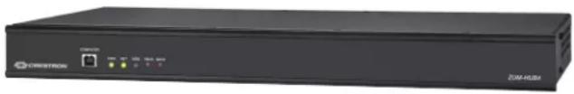
The ZUM-HUB4 enables centralized management for Zūm® commercial lighting systems of up to 1,000 rooms with an Ethernet switch (sold separately) across Zūm wired, Zūm wireless, and external spaces. The device provides a web-based user interface for control. A built-in time clock enables room lighting and occupancy and vacancy sensing automation. The ZUM-HUB4 can also be integrated with other Crestron lighting systems and control systems.
The ZUM-HUB4 is featured in three kits.
- ZUML-HUB4-GW: 4-Series™ Control Processor for Zūm® Lighting Control System with Wireless Gateway and Power Supply
Contains:
- ZUM-HUB4 and PW-2420RU power pack
ZUMNET-GATEWAY: Zūm® Net Wireless Gateway for Zūm Light Control System
PW-2407WU: Wall Mount Power Pack, 24VDC, 0.75A, 2.1 mm, Universal For use with the ZUMNET-GATEWAY
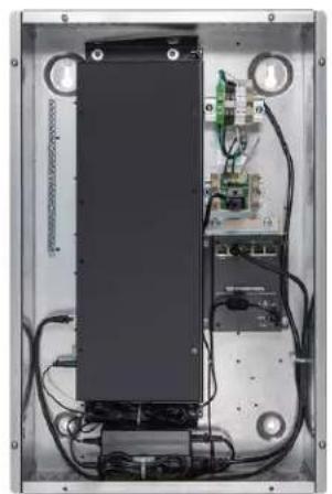
- ZUML-HUB4-PAK: Zūm® Lighting Control Processor Panel, Basic
Contains:
- ZUM-HUB4 and PW-2420RU power pack
CEN-SW-POE-5: 5-Port PoE Switch
GLEX-FT-24-HC: Feed-Through Enclosure, 24 Circuits, Hinged Cover
- ZUML-HUB4-CN-PAK: Züm® Lighting Control Processor Panel, Expanded
Contains:
- ZUM-HUB4 and PW-2420RU power pack
- DIN-AP4: 4-Series™ DIN Rail Control System
DIN-EN-6X18: Enclosure for DIN Rail Devices, 6 DIN Rails, 18 M Wide
CEN-SW-POE-5 (x2): 5-Port PoE Switch
• DIN-HUB (x2): DIN Rail Cresnet Distribution Hub
DIN-PWS60 (x2): DIN Rail 60 Watt Cresnet® Power Supply For use with the DIN-HUB
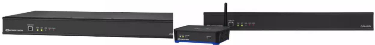
natural_image
Exterior view of a network equipment setup including a CREDITRON switch, wireless router, and broadband cable (no visible text or symbols)ZUM-HUB4 ZUML-HUB4-GW
natural_image
Interior view of an electronic device showing internal components and wiring (no visible text or symbols)
natural_image
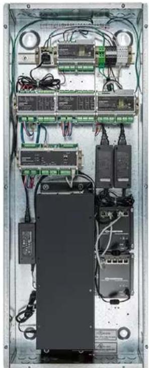
Interior view of an electronic equipment enclosure showing internal components like modules, connectors, and wiring (no visible text or labels)ZUML-HUB4-PAK ZUML-HUB4-CN-PAK
Software
Zūm Wired offers a configuration and a program license for the ZUM-HUB4.
Zūm App
The Crestron Zūm® Lighting Configuration App (CRESTRON-ZUM) enables management of Zūm spaces and devices via a Bluetooth® connection on an Apple® iOS® or Android™ device. Simply pair a mobile device running the app with a ZUMMESH-NETBRIDGE or ZUMLINK-KP to manage Zūm spaces or individual Zūm device settings. Download the Crestron Zūm app from the Google Play™ or Apple App Store® online store.
Custom Program License for the ZUM-HUB4
The SW-HUB4-PROG is a software license that activates the custom program slot on the ZUM-HUB4 control system.
The custom program slot allows a ZUM-HUB4 control system to run a custom program in parallel with the centralized management native to the ZUM-HUB4. Create and update programs that provide custom functionality without affecting the centralized management of the ZUM-HUB4.
To obtain an SW-HUB4-PROG license, complete the Request for SW-HUB4-PROG License form.
For support, contact license@crestron.com.
Accessories
Züm Wired accessories include cables, power supply, custom programming for the ZUM-HUB4, and button trees for keypads.
Cables
Züm Wired cables terminate with RJ-45 connectors for easy wiring. The cables area available in various lengths for both Züm Link and Züm Net applications.
Zūm Net Wiring
The CBL-CAT5E-ZUMNET-P CAT5e cable provides a reliable Ethernet connection for Zūm Net devices within a Zūm® Wired commercial lighting system. The CBL-CAT5E-ZUMNET-P wiring is housed in a plenum-rated jacket, and is available in four lengths from 25 ft (8 m) to 500 ft (152 m) to provide maximum flexibility for LAN wiring.
• CBL-CAT5E-ZUMNET-P-25
• CBL-CAT5E-ZUMNET-P-50
• CBL-CAT5E-ZUMNET-P-100

natural_image
Purple wired Ethernet cable with two connectors (no text or symbols visible)Zūm Link Wiring
The CBL-CAT5E-ZUMLINK-P CAT5e cable provides power and data connections for Zūm Link devices within a Zūm® Wired commercial lighting system. The CBL-CAT5E-ZUMLINK-P wiring is housed in a plenum-rated jacket, and is available in seven lengths from 6 in. (152 mm) to 500 ft (152 m) to provide maximum flexibility for LAN wiring. The 12 ft (4 m) and 25 ft (8 m) cables are also offered in 10 packs.
• CBL-CAT5E-ZUMLINK-P-0.5
• CBL-CAT5E-ZUMLINK-P-3
• CBL-CAT5E-ZUMLINK-P-6
• CBL-CAT5E-ZUMLINK-P-12
• CBL-CAT5E-ZUMLINK-P-25
• CBL-CAT5E-ZUMLINK-P-50
• CBL-CAT5E-ZUMLINK-P-12-10PK
• CBL-CAT5E-ZUMLINK-P-25-10PK

natural_image
Close-up of two orange Ethernet cables with connectors (no text or symbols visible)Adapter Cable
The Zūm® Wired ZUMLINK-CONV-CN adapter cable allows Zūm wired devices with Zūm Link communication to integrate via Cresnet® for legacy controls. The plenum-rated adapter converts a single female RJ-45 Zūm Link port connection to use on the Cresnet network. Cresnet screw terminals provide a contact closure input with the ability to trigger Zūm devices into Emergency Override mode. For flexible in-room wiring, daisy chain Zūm Link with the ZUMLINK-SPLTR-RJ45 RJ-45 splitter to avoid dead ends.
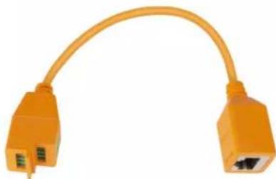
natural_image
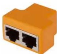
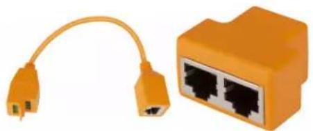
Orange Ethernet cable with two ports, no text or symbols visibleRJ-45 Splitter
The Zūm® Wired ZUMLINK-SPLTR-RJ45 RJ-45 splitter enables one CBL-CAT5E-ZUMLINK-P cable to output two Zūm Link ports. It is plenum rated and works with Zūm Link devices. For flexible, in-room wiring, use with the ZUMLINK-CONV-CN to daisy chain Zūm Link devices with Cresnet® devices.
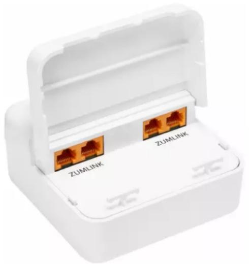
Zūm Link Power Supply
The Zūm® Wired ZUMLINK-JBOX-PSU power supply delivers additional Zūm Link power for in-room lighting control. Equipped with four Zūm Link connections, it provides power distribution and simple wiring using CBL-CAT5E-ZUMLINK-P cables (sold separately, refer toCables on page 14) to other Zūm Link devices.
natural_image
White plastic medical device with two RJ48 connectors labeled 'ZUMLINK' (no additional text or symbols visible)Rocker Button and Button Trees
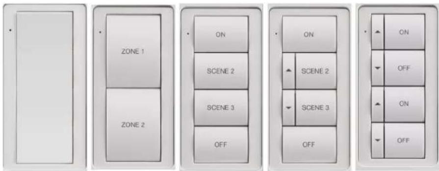
The ZUMLINK-BTN bezel with rocker button or button tree allows for easy customization of a ZUMLINK-KP Zūm® Wired Keypad (sold separately, refer to Keypad on page 10) and is available in almond, black, red, gray, or white. The ZUMLINK-KP comes installed with a white ZUMLINK-BTNR ENGRAVED rocker button, but may be replaced with any of the other ZUMLINK-BTN button trees.
ZUMLINK-BTNR ZUMLINK-BTN2 ZUMLINK-BTN4 ZUMLINK-BTN6 ZUMLINK-BTN8
natural_image
Simple rectangular frame with a small dot on the left side (no text or symbols)
text_image
ZONE 1 ZONE 2
text_image
ON SCENE 2 SCENE 3 OFF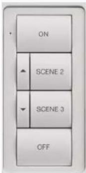
text_image
ON SCENE 2 SCENE 3 OFF
text_image
ON OFF ON OFFFeatures
Refer to the following sections for more information on the features provided by various Zūm Wired devices.
- Load Controller Features
- Keypad Features
• Presence Detector Features - Hub Features
- Software Features
- Cable Features
• Cable Accessory Features
• Power Supply Features - Rocker and Button Tree Features
Load Controller Features
Zūm Wired load controllers include:
• ZUMNET-JBOX-16A-LV on page 18
• ZUMNET-JBOX-DALI on page 19
• ZUMLINK-JBOX-16A-LV on page 21
• ZUMLINK-JBOX-20A-PLUG on page 22
• ZUMLINK-JBOX-20A-SW on page 23
• ZUMLINK-EXP-16A-DIMU on page 24
ZUMNET-JBOX-16A-LV

natural_image
White electronic device with three labeled connectors (ZUMLINK, 24V D. D'01R, ZUMNET) and a green connector, no visible text or symbols beyond labels.- Zūm® wired junction box mounted lighting load dimmer
- Dimming control of 0-10V LED drivers or 4-wire fluorescent ballasts
- Integration with Zūm keypads, presence detectors, and daylight sensors (sold separately)
- Ethernet network connection to ZUM-HUB4 a control system (sold separately)
- Integrated contact closure input
ZūmNet Wired Technology
In a Zūm network, Zūm Net load controllers facilitate communications between rooms via Ethernet and can be daisy-chained for network expansion. Each device in the chain communicates to a Zūm Hub control system for centralized monitoring, management, and reporting. Zūm Link devices connect to Zūm Net devices to provide in-room lighting control. Similar to the Zūm Wireless system, Zūm Link devices work together in a local ecosystem to provide customized solutions as needed.
Zūm Link Wired Technology
Zūm Link technology enables in-room lighting control through keypads and sensors wired to controllers. Zūm Wired devices connect via CBL-CAT5E-ZUMLINK-P CAT5e cable (sold separately, refer to Cables on page 14) to RJ-45 ports provide simple daisy-chaining and lighting control of compatible loads. The Zūm Wired devices work together in a local ecosystem to provide customized solutions using the Zūm app.
Energy Efficiency
The load controllers are capable of energy monitoring through custom programming. Occupancy sensor, vacancy sensor, and daylight sensor connectivity enables significant energy savings. To reduce energy usage, lights turn off automatically when the room is vacant and dim gradually depending on the amount of natural daylight in the room.
Easy Installation
For flexibility and ease-of-use, install Zūm devices (load controllers, keypads, and presence detectors, refer to Overview on page 8) and connect them with Zūm Link (CBL-CAT5E-ZUMLINK-P) or Zūm Net (CBL-CAT5E-ZUMNET-P) CAT5e cable (refer to Cables on page 14). Nonsystem presence detectors may also be installed to any load controller with analog inputs. Room setup can be accomplished quickly through the Zūm app. A finished installation requires a decorator-style faceplate (FP-G Series, sold separately).
Override Contact Closure Input
An integrated contact closure provides the means to place all connected Züm Net and Züm Link devices into Emergency Override mode.
ZUMNET-JBOX-DALI

natural_image
White wireless router adapter with three labeled ports (ZUMLINK, 2AV DOW, ZUMNET LAN) and a green connector on the base (no text beyond labels)- Zūm® wired junction box mounted DALI® drivers lighting controller
• Control of DALI compliant dimmable LED or fluorescent loads -
Integration with Zūm keypads, presence detectors, and daylight sensors (sold separately)
-
Ethernet network connection to ZUM-HUB4 a control system (sold separately)
- Integrated contact closure input
Zūm Net Wired Technology
In a Zūm network, Zūm Net load controllers facilitate communications between rooms via Ethernet and can be daisy-chained for network expansion. Each device in the chain communicates to a Zūm Hub control system for centralized monitoring, management, and reporting. Zūm Link devices connect to Zūm Net devices to provide in-room lighting control. Similar to the Zūm Wireless system, Zūm Link devices work together in a local ecosystem to provide customized solutions as needed.
Zūm Link Wired Technology
Zūm Link technology enables in-room lighting control through keypads and sensors wired to controllers. Zūm Wired devices connect via CBL-CAT5E-ZUMLINK-P CAT5e cable (sold separately, refer to Cables on page 14) to RJ-45 ports provide simple daisy-chaining and lighting control of compatible loads. The Zūm Wired devices work together in a local ecosystem to provide customized solutions using the Zūm app.
Energy Efficiency
The load controllers are capable of energy monitoring through custom programming. Occupancy sensor, vacancy sensor, and daylight sensor connectivity enables significant energy savings. To reduce energy usage, lights turn off automatically when the room is vacant and dim gradually depending on the amount of natural daylight in the room.
Easy Installation
For flexibility and ease-of-use, install Zūm devices (load controllers, keypads, and presence detectors, refer to Overview on page 8) and connect them with Zūm Link (CBL-CAT5E-ZUMLINK-P) or Zūm Net (CBL-CAT5E-ZUMNET-P) CAT5e cable (refer to Cables on page 14). Nonsystem presence detectors may also be installed to any load controller with analog inputs. Room setup can be accomplished quickly through the Zūm app. A finished installation requires a decorator-style faceplate (FP-G Series, sold separately).
Override Contact Closure Input
An integrated contact closure provides the means to place all connected Zūm Net and Zūm Link devices into Emergency Override mode.
ZUMLINK-JBOX-16A-LV
natural_image
White plastic electronic device casing with internal components, no visible text or symbols on the main body- Zūm® wired junction box mounted lighting load dimmer
- Dimming control of 0-10V LED drivers or 4-wire fluorescent ballasts
- Integration with Zūm keypads, presence detectors, and daylight sensors (sold separately)
• Supports in-room device daisy chaining - Integrated contact closure input
Zūm Link Wired Technology
Zūm Link technology enables in-room lighting control through keypads and sensors wired to controllers. Zūm Wired devices connect via CBL-CAT5E-ZUMLINK-P CAT5e cable (sold separately, refer to Cables on page 14) to RJ-45 ports provide simple daisy-chaining and lighting control of compatible loads. The Zūm Wired devices work together in a local ecosystem to provide customized solutions using the Zūm app.
Energy Management and Efficiency
The load controllers are capable of energy monitoring through custom programming. Occupancy sensor, vacancy sensor, and daylight sensor connectivity enables significant energy savings. To reduce energy usage, lights turn off automatically when the room is vacant and dim gradually depending on the amount of natural daylight in the room.
Easy Installation
For flexibility and ease-of-use, install Zūm devices (load controllers, keypads, and presence detectors, refer to Overview on page 8) and connect them with Zūm Link (CBL-CAT5E-ZUMLINK-P) or Zūm Net (CBL-CAT5E-ZUMNET-P) CAT5e cable (refer to Cables on page 14). Nonsystem presence detectors may also be installed to any load controller with analog inputs. Room setup can be accomplished quickly through the Zūm app. A finished installation requires a decorator-style faceplate (FP-G Series, sold separately).
Override Contact Closure Input
An integrated contact closure provides the means to place all connected Zūm Net and Zūm Link devices into Emergency Override mode.
ZUMLINK-JBOX-20A-PLUG
natural_image
White plastic electronic device with two USB connectors and a green connector, no visible text or symbols on the main body.- Zūm® wired junction box mounted lighting load plug load controller
- Integration with Zūm keypads, presence detectors, and daylight sensors (sold separately)
• Zero-cross switching with the ability to switch control of 20A plug loads
• Supports in-room device daisy chaining - Integrated contact closure input
Zūm Link Wired Technology
Zūm Link technology enables in-room lighting control through keypads and sensors wired to controllers. Zūm Wired devices connect via CBL-CAT5E-ZUMLINK-P CAT5e cable (sold separately, refer to Cables on page 14) to RJ-45 ports provide simple daisy-chaining and lighting control of compatible loads. The Zūm Wired devices work together in a local ecosystem to provide customized solutions using the Zūm app.
Energy Management and Efficiency
The load controllers are capable of energy monitoring through custom programming. Occupancy sensor, vacancy sensor, and daylight sensor connectivity enables significant energy savings. To reduce energy usage, lights turn off automatically when the room is vacant and dim gradually depending on the amount of natural daylight in the room.
Easy Installation
For flexibility and ease-of-use, install Zūm devices (load controllers, keypads, and presence detectors, refer to Overview on page 8) and connect them with Zūm Link (CBL-CAT5E-ZUMLINK-P) or Zūm Net (CBL-CAT5E-ZUMNET-P) CAT5e cable (refer to Cables on page 14). Nonsystem presence detectors may also be installed to any load controller with
analog inputs.Room setup can be accomplished quickly through the Zūm app. A finished installation requires a decorator-style faceplate (FP-G Series, sold separately).
Override Contact Closure Input
An integrated contact closure provides the means to place all connected Zūm Net and Zūm Link devices into Emergency Override mode.
ZUMLINK-JBOX-20A-SW

natural_image
White plastic electronic device casing with internal connectors and a 24V D D 01R label (no readable text beyond branding)- Zūm® wired junction box mounted lighting load switch
- Switching control of LED, fluorescent ballast, incandescent, magnetic low-voltage, electronic low-voltage, neon/cold cathode, and high-intensity discharge
- Integration with Zūm keypads, presence detectors, and daylight sensors (sold separately)
• Zero-cross switch control of 20A, 100-277V high inrush lighting loads
• Supports in-room device daisy chaining - Integrated contact closure input
Zūm Link Wired Technology
Zūm Link technology enables in-room lighting control through keypads and sensors wired to controllers. Zūm Wired devices connect via CBL-CAT5E-ZUMLINK-P CAT5e cable (sold separately, refer to Cables on page 14) to RJ-45 ports provide simple daisy-chaining and lighting control of compatible loads. The Zūm Wired devices work together in a local ecosystem to provide customized solutions using the Zūm app.
Energy Management and Efficiency
The load controllers are capable of energy monitoring through custom programming. Occupancy sensor, vacancy sensor, and daylight sensor connectivity enables significant energy savings. To reduce energy usage, lights turn off automatically when the room is vacant and dim gradually depending on the amount of natural daylight in the room.
Easy Installation
For flexibility and ease-of-use, install Zūm devices (load controllers, keypads, and presence detectors, refer to Overview on page 8) and connect them with Zūm Link (CBL-CAT5E-ZUMLINK-P) or Zūm Net (CBL-CAT5E-ZUMNET-P) CAT5e cable (refer to Cables on page 14). Nonsystem presence detectors may also be installed to any load controller with analog inputs. Room setup can be accomplished quickly through the Zūm app. A finished installation requires a decorator-style faceplate (FP-G Series, sold separately).
Override Contact Closure Input
An integrated contact closure provides the means to place all connected Zūm Net and Zūm Link devices into Emergency Override mode.
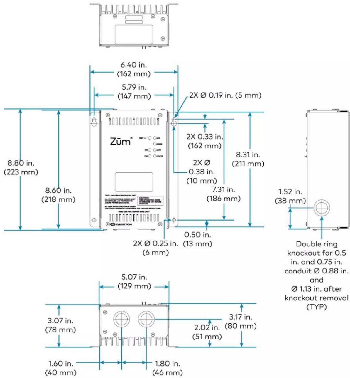
ZUMLINK-EXP-16A-DIMU

text_image
Zūm™ AIRS LPG INTRON AUTO POWER CHINA ZUNUM/OSI-MA-04U INPUT: ON /GT/AC, MIN/PAI MINISTER: MAX/UL 9.4V/400 INSMED LOAD TYPE, INCHORDANCE, ELECTRONIC LOW-VOLTAGE, MACHS TO: MAX VOLTAGE, T-800 FLUORESCENT TYPE 1 (MELONUM) MOTOR USE ONLY ALL COVERING INSURANCE ITEMS WITH AND INSTALLED OUT PONTENSER TO: MAKE POWER DURING ITEMS POWER SERVICE NAME UNLOCK THIS ORDER, ARE INSTALLATION PROCES FROM THE CURRENT INSTRUCTIONS CRED COLD TYPE COOPERATION ONLY CAUTION MAX ON ELECTRIC WATER CONSPRING ONLY AIR LPGS CONTENTS CRESTRONAuto-Detecting Universal Dimming
Under normal operation, the Crestron Züm® Wired Lighting Control detects the connected load type and automatically selects the appropriate operating mode. Reverse phase (trailing edge) mode supports incandescent and electronic low-voltage load types, while forward phase (leading edge) mode supports LED, magnetic low-voltage, neon/cold-cathode, and 2-wire fluorescent load types. Center phase mode is also available, combining reverse and forward phase load control to address special cases. The operative mode is indicated by two LEDs located on the front panel.
Zūm Link Wired Technology
Züm Link technology enables in-room lighting control through keypads and sensors wired to controllers. Züm Wired devices connect via CBL-CAT5E-ZUMLINK-P CAT5e cable (sold separately, refer to Cables on page 14) to RJ-45 ports provide simple daisy-chaining and lighting control of compatible loads. The Züm Wired devices work together in a local ecosystem to
provide customized solutions using the Zūm app.
Energy Efficiency
The load controllers are capable of energy monitoring through custom programming. Occupancy sensor, vacancy sensor, and daylight sensor connectivity enables significant energy savings. To reduce energy usage, lights turn off automatically when the room is vacant and dim gradually depending on the amount of natural daylight in the room.
Plenum Rated NEMA Enclosure
The Crestron Züm® Wired Lighting Control is designed to be mounted to a vertical surface and meets the requirements of UL® 2043 for installation in an environmental air-handling space (plenum) above a suspended ceiling. Conduit knockouts are provided on the bottom and lower sides of the unit. All connections are made via screw terminals behind the front cover.
Keypad Features
Product features for the ZUMLINK-KP are provided below.
natural_image
Simple line drawing of a rectangular frame with a dot at the top-left corner (no text or symbols)(Faceplate not included)
- Provides control of one or more Zūm® wired J-Box Load Controllers
• RS485 communications for increased reliability - Preprogrammed rocker button
- Configurable with two, four, six, or eight engraved or pad printed button trees (ZUMLINK-BTN2, ZUMLINK-BTN4, ZUMLINK-BTN6, ZUMLINK-BTN8, not included)
- Powered by 24V Zūm Link bus
- Two RJ-45 connections for device daisy-chaining
- Standard 3.5 in. (89 mm) deep electrical box installation
- Button tree and bezel available in almond, black, gray, red, and white finish
- Matching decorator-style faceplate required (FP-G Series, not included)
Zūm Link Wired Technology
Zūm Link technology enables in-room lighting control through keypads and sensors wired to controllers. Zūm Wired devices connect via CBL-CAT5E-ZUMLINK-P CAT5e cable (sold separately, refer to Cables on page 14) to RJ-45 ports provide simple daisy-chaining and lighting control of compatible loads. The Zūm Wired devices work together in a local ecosystem to provide customized solutions using the Zūm app.
Button Configurations
The keypad is equipped with a single, white rocker button for switching or dimming control and is configurable with four, six, or eight pad printed or engravable button trees (sold separately).
Replacement configurations are available in an almond, black, gray, red or white finish.
Easy Installation
For flexibility and ease-of-use, install Zūm devices (load controllers, keypads, and presence detectors) and connect them with Zūm Link (CBL-CAT5E-ZUMLINK-P) or Zūm Net (CBL-CAT5E-ZUMNET-P) CAT5e cable. Nonsystem presence detectors may also be installed to any load controller with analog inputs. Room setup can be accomplished quickly through the Zūm app. A finished installation requires a decorator-style faceplate (FP-G Series, sold separately).
The Crestron Zūm® Wired Lighting Control installs in a standard four-inch square junction box. Depending on the installation requirements of the space, the Crestron Zūm® Wired Lighting Control can be installed with the connections facing out or into the junction box. Connect the Crestron Zūm® Wired Lighting Control to Zūm devices (load controllers, keypads, and sensors) utilizing Zūm Link connections.
For flexibility and ease-of-use, install Zūm devices (load controllers, keypads, and presence detectors, refer to Overview) and connect them with Zūm Link (CBL-CAT5E-ZUMLINK-P) or Zūm Net (CBL-CAT5E-ZUMNET-P) CAT5e cable (refer to Cables). Nonsystem presence detectors may also be installed to any load controller with analog inputs. Room setup can be accomplished quickly through the Zūm app. A finished installation requires a decorator-style faceplate (FP-G Series, sold separately).
For flexibility and ease-of-use, Zūm load controllers are installed in a room with Zūm keypads, system presence detectors or nonsystem occupancy or vacancy sensors, and/or a daylight sensor for complete commercial lighting control.
Presence Detector Features
Product features for the Zūm Link Presence Detectors are provided below.
ZUMLINK-IR-QUATTRO-DLS and ZUMLINK-IR-QUATTRO-DLS-RLY

ZUMLINK-IR-QUATTRO-HD-DLS and ZUMLINK-IR-QUATTRO-HD-DLS-RLY
- Ceiling-mount presence sensor
• Passive infrared (PIR), ultrasonic, or dual-technology motion detection
• 360 degree coverage pattern - Fully digital circuitry for low cost and high reliability
• Built-in closed loop daylight sensor - Control system communications the Züm® Link network
- Compatible with Zūm wired keypad
- For the -RLY models, additional relays included for input-relay capable devices
Zūm Link Wired Technology
Zūm Link technology enables in-room lighting control through keypads and sensors wired to controllers. Zūm Wired devices connect via CBL-CAT5E-ZUMLINK-P CAT5e cable (sold separately, refer to Cables on page 14) to RJ-45 ports provide simple daisy-chaining and lighting control of compatible loads. The Zūm Wired devices work together in a local ecosystem to provide customized solutions using the Zūm app.
Easy Installation
For flexibility and ease-of-use, install Zūm devices (load controllers, keypads, and presence detectors, refer to Overview on page 8) and connect them with Zūm Link (CBL-CAT5E-ZUMLINK-P) or Zūm Net (CBL-CAT5E-ZUMNET-P) CAT5e cable (refer to Cables on page 14). Nonsystem presence detectors may also be installed to any load controller with analog inputs.
Easy Commissioning
Finish the installation by quickly commissioning the room through the Zūm app. Expedite commissioning by copying a room configuration and sending it to an identical room. Save a room configuration template and share it via the ZUM-HUB4 or the Zūm app. The ZUMLINK-KP Bluetooth® connection is required to configure a Zūm wired space with the Zūm app.
Hub Features
The ZUM-HUB4 is featured in three kits.
• ZUML-HUB4-GW on page 31
• ZUML-HUB4-PAK on page 32
• ZUML-HUB4-CN-PAK on page 33
ZUM-HUB4
natural_image
Exterior view of a black ZUM-HLM device with indicator lights (no readable text or symbols beyond branding)- Centralized management for Zūm® commercial lighting systems
- Provides web-based user interface for easy configuration, control, scheduling, and monitoring
- Time clock for room lighting automation and sensing behavior
- Daisy-chain up to 20 Zūm Net load controllers (sold separately) via their built-in Zūm Net ports for room-to-room communication
- Use with an Ethernet switch (sold separately) to support multiple Züm Net daisy-chains up to 1,000 rooms
- Daisy-chain up to 32 Zūm Link devices (sold separately) via their built-in Zūm Link ports for in-room communication
- BACnet™ communication supports control for up to 9,000 BACnet objects
• Dedicated Control Subnet
• Gigabit Ethernet networking - Enterprise-grade security
- Enables integration with other Crestron lighting systems, control systems, touch screens, shading, HVAC, and more
- Single-space rack-mountable
• Universal 100-240V external power supply
Zūm Net Wired Technology
Zūm Net wired technology offers room-to-room communication. Control a room with one Zūm Net device (ZUMNET-JBOX-DALI, ZUMNET-JBOX-16A-LV, sold separately), and daisy-chain up to 20 Zūm Net devices with CBL-CAT5E-ZUMNET-P cable. For centralized management of a Zūm Wired System, connect the chain directly to a ZUM-HUB4 or multiple chains to an Ethernet switch (sold separately) to support up to 1,000 rooms.
Web-Based Management
The web browser user interface can manage, monitor, and schedule all of the available rooms on the network. Use a laptop computer (not included) to configure devices to work with the ZUM-HUB4. Active lighting scenes, daylight levels, occupancy detection, and scheduled time clock events are displayed. Errors are shown to facilitate troubleshooting.
Time Clock
A built-in time clock enables automated lighting control based on the time of day. Assign a Room Category (such as Office or Hallway) for consistent control and programming across multiple rooms. The clock allows Day Pattern arrangement for each Room Category, with up to 24 Room States scheduled over a 24 hour period. Different Day Patterns can be defined and assigned to the calendar, which is pre-populated with typical day patterns and a selection of U.S. holidays.
BACnet™ Communications Protocol
Communicate with a Building Management System (BMS) to provide control of fire/life safety, lighting, and other building automation systems. The ZUM-HUB4 supports up to 1,9809,000 BACnet objects.
Crestron XiO Cloud® Service Integration
Use Crestron XiO Cloud functionality for remote commissioning and monitoring of a ZUM-HUB4 control system.
Zūm Wireless Integration
Integration with existing Zūm Wireless installations is achieved with a ZUMNET-GATEWAY (not supplied), which connects to the ZUM-HUB4 via Ethernet.
Zūm System Integration with Other Crestron Control Systems
In addition to managing rooms equipped with Zūm lighting control, the ZUM-HUB4 enables integration with other Crestron systems over an Ethernet connection. Two methods of integration are available:
- External Rooms: A virtual room using legacy or conventional Crestron lighting control can be added to the Zūm network to be monitored, controlled and scheduled.
- Mirrored Rooms: An external Crestron system controls and monitors a room equipped with a Zūm system. Mirrored rooms allow for room control with a Crestron touch screen or handheld remote, as well as integration with shading, climate control, AV, and other equipment. ^1,2
ZUML-HUB4-GW

natural_image
Exterior view of a wireless network device with a USB port and external antenna (no visible text or symbols)- Facilitates quick setup of a centrally managed Zūm light control system
- Contains a ZUM-HUB4 Zūm hub, PW-2420RU power pack, ZUMNET-GATEWAY Zūm gateway, and PW-2407WU power supply for the gateway
For additional details and specifications, refer to the ZUM-HUB4 information in this guide and the PW-2420RU, ZUMNET-GATEWAY, and PW-2407WU product pages.
ZUML-HUB4-PAK

natural_image
Interior view of an electronic device enclosure showing internal components and wiring (no visible text or symbols)• Facilitates quick setup of a centrally managed Zūm light control system
- Convenient preassembled lighting control cabinet
- Contains a ZUM-HUB4 Züm hub, PW-2420RU power pack, CEN-SW-POE-5 switch, and GLEX-FT-24-HC enclosure
For additional details and specifications, refer to the ZUM-HUB4 information in this guide and the PW-2420RU, CEN-SW-POE-5, and GLEX-FT-24-HC product pages.
ZUML-HUB4-CN-PAK
natural_image
Interior view of an electronic equipment cabinet with multiple connected modules and wiring (no visible text or labels)• Facilitates quick setup of a centrally managed Züm light control system
- Convenient preassembled lighting control cabinet
- Contains a ZUM-HUB4 Züm hub, PW-2420RU power pack, DIN-EN-6X18 wall mount enclosure, DIN-AP4 control processor, two CEN-SW-POE-5 switches, two DIN-HUB Cresnet hubs, and two DIN-PWS60 power supplies for the DIN-HUB
For additional details and specifications, refer to the ZUM-HUB4 information in this guide and the PW-2420RU, DIN-AP4, DIN-HUB, DIN-PWS60, CEN-SW-POE-5, and DIN-EN-6X18 product pages.
-
SIMPL+® software modules are provided for use in commissioning a Crestron control system to work with the ZUM-HUB4. The software modules run within the control system program and provide virtual connections for all the necessary intersystem control signals. A separate dedicated module is required for each external and mirrored room. Control systems are limited in the number of modules supported, ranging from 0 to 2001000 depending on the model. For further assistance, please contact Crestron Commercial Lighting Support via email at clclighting@crestron.com or by calling 855-644-7643.
-
Other Crestron control systems must be commissioned to provide the control logic required to communicate and operate as part of the Zūm network. Once integrated, each external room effectively becomes a part of the Zūm ecosystem.
Software Features
Refer to the following sections for Zūm app and ZUM-HUB4 custom program license software features.
Zūm App
Features for the Zūm app are provided below.
- Mobile configuration tool for Zūm® wired and wireless commercial lighting systems
- Compatible with iOS ^ and Android ^TM operating systems
- Bluetooth® low energy (BLE) communications
Zūm Space Management
Zūm spaces are manageable via the Zūm lighting configuration app. Open the Crestron Zūm app and all nearby Zūm spaces appear. Connect to a Zūm space and easily control and manage the space's name, security settings, and network configuration.
Zūm Device Management
Settings for individual load controllers, sensors, and keypads are modifiable from the Zūm lighting configuration app. Dimming levels, sensor sensitivity, and lighting scenes are all configurable through an intuitive onscreen procedure.
Bluetooth Connectivity
The Zūm lighting configuration app uses Bluetooth to easily pair with a ZUMMESH-NETBRIDGE for wireless installations or ZUMLINK-KP for wired installations. The signal strength between a mobile device and a Zūm device is displayed on the app's home screen for user convenience.
ZUM-HUB4 Custom Program License
- Activates a custom program slot on the ZUM-HUB4
- Run custom programming alongside native ZUM-HUB4 functionality
- Maintain centralized management of the system
Cable Features
Cables are available for Zūm Net and Zūm Link applications.
• CBL-CAT5E-ZUMNET-P Zūm Link Wiring on page 35
• CBL-CAT5E-ZUMLINK-P Züm Link Wiring on page 35

natural_image
Two types of Ethernet cables shown in purple and orange, no text or symbols visibleCBL-CAT5E-ZUMNET-P CBL-CAT5E-ZUMLINK-P
CBL-CAT5E-ZUMNET-P Zūm Link Wiring
- Preterminated CAT5e cable for Zūm Net device communications between rooms in a Zūm® Wired system
• RS485 Communications - Plenum-rated jacket
• RJ-45 connectors with dust cap
• Available in four lengths
CBL-CAT5E-ZUMNET-P cables connect a Zūm Net device to a ZUM-HUB4 control system (refer to Hub on page 12), an Ethernet switch, or to other Zūm Net devices. This enables LAN communications and device daisy-chaining between rooms within a Zūm Wired system.
CBL-CAT5E-ZUMLINK-P Zūm Link Wiring
- Preterminated CAT5e cable for Zūm Link device communications within a Zūm® Wired space
• RS485 Communications - Plenum-rated jacket
- RJ-45 connectors
• Available in seven lengths
CBL-CAT5E-ZUMLINK-P cables distribute power between Zūm Link devices for in-room device daisy chaining. They provide communications between load controllers, keypads, sensors, and any other devices within a Zūm Wired room as well as transport emergency override capabilities. CBL-CAT5E-ZUMLINK-P cables also distribute power and data between Zūm Net and Zūm Link devices to facilitate network expansion.
Cable Accessory Features
Cables accessories include the ZUMLINK-CONV-CN adapter cable and the ZUMLINK-SPLTR-RJ45 splitter.
• ZUMLINK-CONV-CN on page 36
• ZUMLINK-SPLTR-RJ45 on page 36
natural_image
Orange Ethernet connector with two ports and a cable, no text or symbols visibleZUMLINK-CONV-CN ZUMLINK-SPLTR-RJ45
ZUMLINK-CONV-CN
- Connects Cresnet devices to the Züm Link network via a CBL-CAT5E-ZUMLINK-P cable.
- Provides an RJ-45 female port and Cresnet network screw terminals
• Daisy chain Zūm Link devices with the ZUMLINK-SPLTR-RJ45 to avoid dead ends - Plenum-rated cable
Zūm Link Wired Technology
Zūm Link technology enables in-room lighting control through keypads and sensors wired to controllers. Zūm Wired devices connect via CBL-CAT5E-ZUMLINK-P CAT5e cable (sold separately, refer to Cables on page 14) to RJ-45 ports provide simple daisy-chaining and lighting control of compatible loads. The Zūm Wired devices work together in a local ecosystem to provide customized solutions using the Zūm app.
Cresnet Wired Network
The Zūm devices use the dependable Cresnet wired network for communication between devices. The Cresnet bus offers easy wiring and configuration, carrying bidirectional communication and 24VDC power to each device over a simple 4-conductor cable.
ZUMLINK-SPLTR-RJ45
The Zūm® Wired ZUMLINK-SPLTR-RJ45 RJ-45 splitter enables one CBL-CAT5E-ZUMLINK-P cable to output two Zūm Link ports. It is plenum rated and works with Zūm Link devices. For flexible, in-room wiring, use with the ZUMLINK-CONV-CN to daisy chain Zūm Link devices with Cresnet® devices.
Power Supply Features
Product features for the ZUMLINK-JBOX-PSU are provided below.
natural_image
White medical device with two orange Ethernet connectors labeled 'ZUMLINK' (no additional text or symbols visible)- Zūm® wired junction box mounted power supply
- Powers Zūm keypads, presence detectors, and daylight sensors (sold separately)
Easy Installation
For flexibility and ease-of-use, install Zūm devices (load controllers, keypads, and presence detectors, refer to Overview on page 8) and connect them with Zūm Link (CBL-CAT5E-ZUMLINK-P) or Zūm Net (CBL-CAT5E-ZUMNET-P) CAT5e cable (refer to Cables on page 14). Nonsystem presence detectors may also be installed to any load controller with analog inputs.
Rocker and Button Tree Features
Product features for the rocker and button tree configurations are provided below.
ZUMLINK-BTNR ZUMLINK-BTN2 ZUMLINK-BTN4 ZUMLINK-BTN6 ZUMLINK-BTN8
text_image
ZONE 1 ZONE 2 ON SCENE 2 SCENE 3 OFF ON SCENE 2 SCENE 3 OFF ON OFF ON OFF- Provides multiple button configurations for ZUMLINK-KP keypads
- Two-piece installation: button tree or rocker with matching bezel
- Easily swap button configurations in the field
• Available as a rocker button or in configurations of two, four, six, or eight button trees - Pad printed labeling or custom engravings available
- Offered in black, white, almond, gray, or red finishes
Pad Printing
Pad printed button trees allow for convenient preprinted labeling on any ZUMLINK-BTN configuration. Visit the following product pages to view the various button configurations and colors offered for the pad printed models.
• ZUMLINK-BTN2: ZONE 1, ZONE 2
• ZUMLINK-BTN4: ON, SCENE 2, SCENE 3, OFF
• ZUMLINK-BTN6: ON, SCENE 2, SCENE 3, OFF, ∧, ∨
• ZUMLINK-BTN8: ON, OFF, ON, OFF, ∧, ∨, ∧, ∨
Custom Engraving
Crestron Engraver software makes it easy to specify and order button trees with custom engravings for a ZUMLINK-KP Züm Wired Keypad. Visit the following product pages to view the various button configurations and colors offered for the custom engraved models.
• ZUMLINK-BTN2 ENGRAVED
• ZUMLINK-BTNR ENGRAVED
• ZUMLINK-BTN4 ENGRAVED
• ZUMLINK-BTN6 ENGRAVED
• ZUMLINK-BTN8 ENGRAVED
Blank Buttons
In addition to custom engraving and pad printed buttons, blank buttons are available. Visit the following product pages to view the various button configurations and colors offered.
• ZUMLINK-BTN2 BLANK
• ZUMLINK-BTNR BLANK
• ZUMLINK-BTN4 BLANK
• ZUMLINK-BTN6 BLANK
• ZUMLINK-BTN8 BLANK
Application Scenarios
Refer to the following illustrations for common applications.
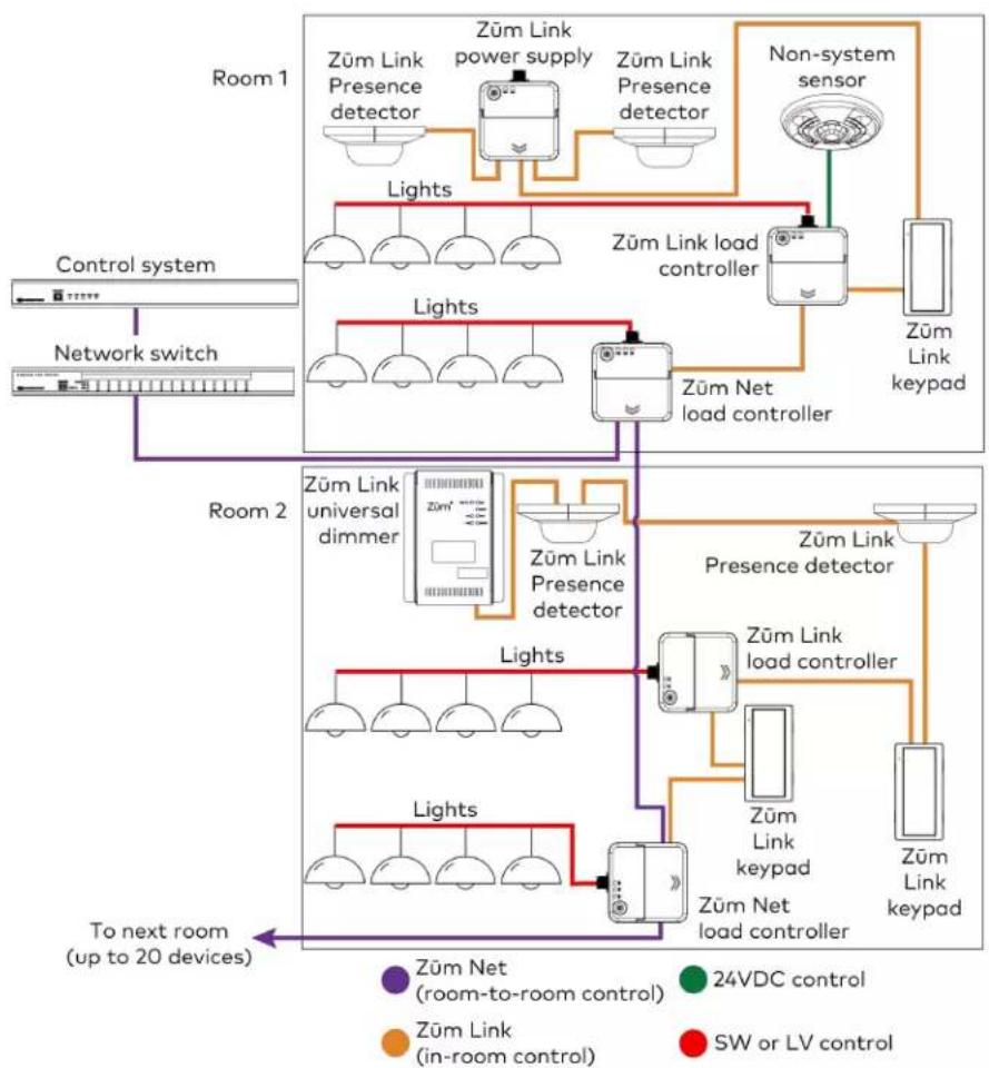
Züm Wired System Diagram
flowchart
graph TD
    subgraph Room 1
        A["Züm Link Presence detector"] --> B["Züm Link power supply"]
        B --> C["Züm Link Presence detector"]
        D["Non-system sensor"] --> E["Züm Link load controller"]
        E --> F["Züm Link keypad"]
    end

    subgraph Room 2
        G["Züm Link universal dimmer"] --> H["Züm Link Presence detector"]
        H --> I["Züm Link presence detector"]
        J["Züm Link universal dimmer"] --> K["Züm Link presence detector"]
        K --> L["Züm Link load controller"]
        M["Züm Link universal dimmer"] --> N["Züm Link presence detector"]
        N --> O["Züm Link load controller"]
        P["Züm Link universal dimmer"] --> Q["Züm Link presence detector"]
        Q --> R["Züm Link load controller"]
        S["Züm Link universal dimmer"] --> T["Züm Link presence detector"]
        T --> U["Züm Link load controller"]
        V["Züm Link universal dimmer"] --> W["Züm Link presence detector"]
        W --> X["Züm Link load controller"]
        Y["Züm Link universal dimmer"] --> Z["Züm Link presence detector"]
        Z --> AA["Züm Link load controller"]
        AB["Züm Link universal dimmer"] --> AC["Züm Link presence detector"]
        AC --> AD["Züm Link load controller"]
        AE["Züm Link universal dimmer"] --> AF["Züm Link presence detector"]
        AF --> AG["Züm Link load controller"]
        AH["Züm Link universal dimmer"] --> AI["Züm Link presence detector"]
        AI --> AJ["Züm Link load controller"]
        AK["Züm Link universal dimmer"] --> AL["Züm Link presence detector"]
        AL --> AM["Züm Link load controller"]
        AN["Züm Link universal dimmer"] --> AO["Züm Link presence detector"]
        AO --> AP["Züm Link load controller"]
        AQ["Züm Link universal dimmer"] --> AR["Züm Link presence detector"]
        AR --> AS["Züm Link load controller"]
        AT["To next room (up to 20 devices)"] --> AU["Light"]
    end

    style Room 1 fill:#f9f,stroke:#333
    style Room 2 fill:#f9f,stroke:#333
    style Room 3 fill:#f9f,stroke:#333
    style Room 4 fill:#f9f,stroke:#333
    style Room 5 fill:#f9f,stroke:#333
    style Room 6 fill:#f9f,stroke:#333
    style Room 7 fill:#f9f,stroke:#333
    style Room 8 fill:#f9f,stroke:#333
    style Room 9 fill:#f9f,stroke:#333
    style Room 10 fill:#f9f,stroke:#333
    style Room 11 fill:#f9f,stroke:#333
    style Room 12 fill:#f9f,stroke:#333
    style Room 13 fill:#f9f,stroke:#333
    style Room 14 fill:#f9f,stroke:#333
    style Room 15 fill:#f9f,stroke:#333
    style Room 16 fill:#f9f,stroke:#333
    style Room 17 fill:#f9f,stroke:#333
    style Room 18 fill:#f9f,stroke:#333
    style Room 19 fill:#f9f,stroke:#333
    style Room 20 fill:#f9f,stroke:#333
    style Room 21 fill:#f9f,stroke:#333
    style Room 22 fill:#f9f,stroke:#333
    style Room 23 fill:#f9f,stroke:#333
    style Room 24 fill:#f9f,stroke:#333
    style Room 25 fill:#f9f,stroke:#333
    style Room 26 fill:#f9f,stroke:#333
    style Room 27 fill:#f9f,stroke:#333
    style Room 28 fill:#f9f,stroke:#333
    style Room 29 fill:#f9f,stroke:#333
    style Room 30 fill:#f9f,stroke:#333
    style Room 31 fill:#f9f,stroke:#333
    style Room 32 fill:#f9f,stroke:#333
    style Room 33 fill:#f9f,stroke:#333
    style Room 34 fill:#f9f,stroke:#333
    style Room 35 fill:#f9f,stroke:#333
    style Room 36 fill:#f9f,stroke:#333
    style Room 37 fill:#f9f,stroke:#333
    style Room 38 fill:#f9f,stroke:#333
    style Room 39 fill:#f9f,stroke:#333
    style Room 40 fill:#f9f,stroke:#333
    style Room 41 fill:#f9f,stroke:#333
    style Room 42 fill:#f9f,stroke:#333
    style Room 43 fill:#f9f,stroke:#333
    style Room 44 fill:#f9f,stroke:#333
    style Room 45 fill:#f9f,stroke:#333
    style Room 46 fill:#f9f,stroke:#333
    style Room 47 fill:#f9f,stroke:#333
    style Room 48 fill:#f9f,stroke:#333
    style Room 49 fill:#f9f,stroke:#333
    style Room 50 fill:#f9f,stroke:#333
NOTES:
- Daisy-chain up to 20 Züm Net devices (up to 328 ft (100 m) between Züm Net devices) with purple CBL-CAT5E-ZUMNET-P RJ-45 cables (sold separately).
- Do not exceed three network switches between a ZUM-HUB4 and a Zūm Net device.
- System sensors communicate digitally via Zūm Link. Non-system sensors communicate via an analog connection on a Zūm Wired load controller.
Integrating a Legacy Lighting System into a Zūm System
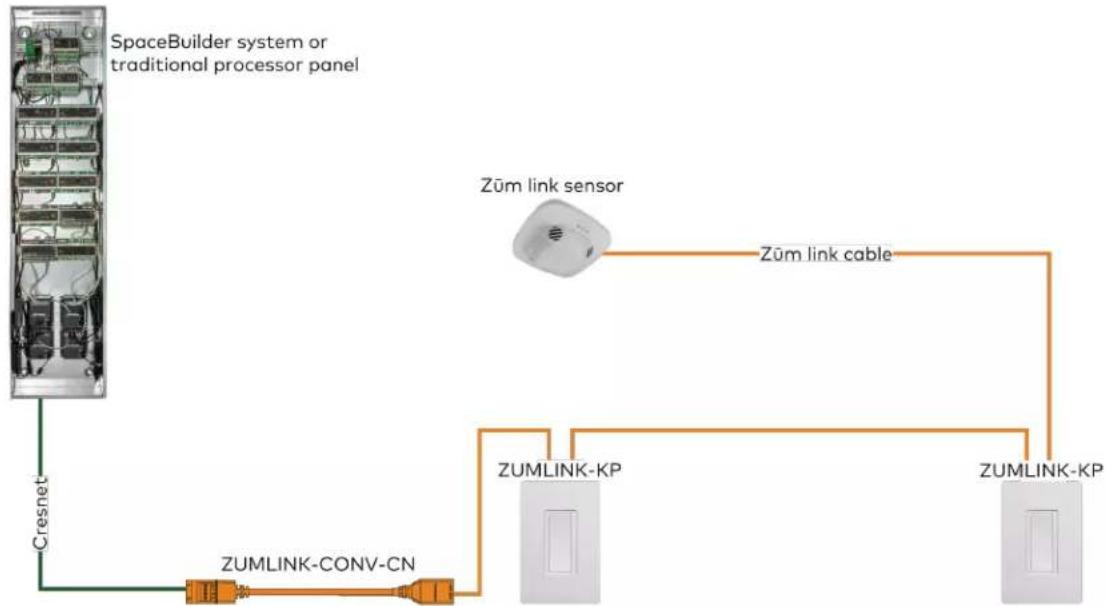
flowchart
graph TD
    A["SpaceBuilder system or traditional processor panel"] --> B["Cresnet"]
    B --> C["ZUMLINK-CONV-CN"]
    C --> D["ZUMLINK-KP"]
    D --> E["ZUMLINK-KP"]
    F["Zum link sensor"] --> G["Zum link cable"]
    G --> D
Using a Züm Link Splitter (ZUMLINK-SPLTR-RJ45)

flowchart
graph TD
    A["ZUMNET-JBOX-16A-LV"] -->|Zūm link cable| B["ZUMLINK-SPLTR-RJ45"]
    C["ZUMLINK-KP"] --> B
    D["ZUMLINK-KP"] --> B
    E["ZUMLINK-JBOX-16A-LV"] --> B
    F["ZUMLINK-KP"] --> B
    G["ZUMLINK-JBOX-16A-LV"] --> B
    H["ZUMLINK-KP"] --> B
    I["ZUMLINK-JBOX-16A-LV"] --> B
Specifications
Refer to the following sections for more information on the specifications for various Züm Wired devices.
- Load Controller Specifications
- Keypad Specifications
• Presence Detector Specifications - Hub Specifications
• Zūm App Specifications - Cable Specifications
• Cable Accessory Specifications
• Power Supply Specifications - Rocker and Button Tree Specifications
Load Controller Specifications
Zūm Wired load controllers include:
• ZUMNET-JBOX-16A-LV Product Specifications on page 43
• ZUMNET-JBOX-DALI Specifications on page 45
• ZUMLINK-JBOX-16A-LV Specifications on page 48
• ZUMLINK-JBOX-20A-PLUG Specifications on page 51
• ZUMLINK-JBOX-20A-SW Specifications on page 54
• ZUMLINK-EXP-16A-DIMU Specifications on page 57
ZUMNET-JBOX-16A-LV Product Specifications
Load Control
Dim Load Types 0-10V LED drivers or electronic ballasts (4-wire)
Switch Load Types LED, electronic ballasts, incandescent, magnetic low-voltage, electronic low-voltage, neon/cold cathode, high-intensity discharge, small motor loads
Load Rating 16A 100-277VAC, 50/60 Hz;
0.5 HP @ 120-277VAC
Line Voltage 100-277VAC, 50/60 Hz
Dim Control Output 0-10VDC, 60mA maximum sink or source
Short Circuit Protection 40A non-replaceable fuse
Zūm Link Power Bus Requirements
Wired Communications
ZUMNET (LAN) (2) RJ-45 ports;
Input for control system connection or Zūm Net device;
Output for Zūm Net device daisy-chaining
ZUMLINK (ROOM) (2) RJ-45 ports;
In-room Zūm Link device daisy-chaining;
85mA power available for Zūm Link devices, including ZUMLINK-KP keypads
24V, OCC, GND Occupancy sensor input;
85mA available output current;
Spring clamp connector
24V, PHO, GND Photo sensor input;
Spring clamp connector
OVR, GND Override control input;
Spring clamp connector
Controls and Indicators
TEST (1) Pushbutton and (1) green LED;
Push to toggle the switched load output on and off;
Press and hold to cycle the dimming level up and down;
LED indicates that the load is turned on;
LED lights and flashes during room setup and factory reset
ZUMLINK Status (1) bi-color green/red LED;
LED lights green in normal operation;
LED lights red when a fault is detected
ZUMNET Status (1) bi-color green/red LED;
LED lights green in normal operation;
LED lights red when a fault is detected
Connections
Hot (1) 14 AWG Class 1 flying lead;
Black, line power input
Neutral (1) 14 AWG Class 1 flying lead;
White, neutral
Red (1) 14 AWG Class 1 flying lead, red, AC output
Purple (1) 18 AWG Class 1 flying lead, purple, 0-10VDC dimming control output,
positive
Gray (1) 18 AWG Class 1 flying lead, gray, 0-10VDC dimming control output, negative
Environmental
Temperature 32° to 104°F (0° to 40°C)
Humidity 10% to 90% RH (noncondensing)
Construction
Housing Plastic, white, UL 94 5VA flame rated
Mounting Mounts to the side of a 4 in. square junction box via a 1/2 in. conduit knockout;
Meets the requirements of UL 2043 for installation in an environmental air-handling (plenum) space
Dimensions
Height 4.83 in. (123 mm)
Width 4.25 in. (108 mm)
Depth 2.03 in. (52 mm)
Weight
7 oz (199 g)
Compliance
Regulatory Model: M201933001
cUL916, cUL2043
Intertek® Listed for US & Canada, IC, FCC Part 15 Class A digital device, UL 916, UL 2043, UL 94 5VA
ZUMNET-JBOX-16A-LV Dimension Drawings
ZUMNET-JBOX-DALI Specifications
Load Control
Line Voltage 100-277VAC, 50/60 Hz
Load Types Control of DALI compliant dimmable LED or fluorescent loads
DALI Groups 16
Drivers 64
Zūm Link Power Bus Requirements
Wired Communications
ZUMNET (LAN) (2) RJ-45 ports;
Input for control system connection or Zūm Net device;
Output for Zūm Net device daisy-chaining
ZUMLINK (ROOM) (2) RJ-45 ports;
In-room Zūm Link device daisy-chaining;
85mA power available for Zūm Link devices, including ZUMLINK-KP keypads
24V, OCC, GND Occupancy sensor input;
85mA available output current;
Spring clamp connector
24V, PHO, GND Photo sensor input;
Spring clamp connector
OVR, GND Override control input;
Spring clamp connector
Controls and Indicators
TEST (1) Pushbutton and (1) green LED;
Push to toggle the switched load output on and off;
Press and hold to cycle the dimming level up and down;
LED indicates that the load is turned on;
LED lights and flashes during room setup and factory reset
ZUMLINK Status (1) bi-color green/red LED;
LED lights green in normal operation;
LED lights red when a fault is detected
ZUMNET Status (1) bi-color green/red LED;
LED lights green in normal operation;
LED lights red when a fault is detected
Connections
Hot (1) 14 AWG Class 1 flying lead;
Black, line power input
Neutral (1) 14 AWG Class 1 flying lead;
White, neutral
Purple (1) 18 AWG Class 1 flying lead, purple, DALI input/output, low voltage, positive
Gray (1) 18 AWG Class 1 flying lead, gray, DALI input/output, low voltage, negative
Red (1) 14 AWG Class 1 flying lead, power monitoring, AC output
Environmental
Temperature 32° to 104°F (0° to 40°C)
Humidity 10% to 90% RH (noncondensing)
Construction
Housing Plastic, white, UL 94 5VA flame rated
Mounting Mounts to the side of a 4 in. square junction box via a 1/2 in. conduit knockout;
Meets the requirements of UL 2043 for installation in an environmental air-handling (plenum) space
Dimensions
Height 4.83 in. (123 mm)
Width 4.25 in. (108 mm)
Depth 2.03 in. (52 mm)
Weight
7 oz (199 g)
Compliance
Regulatory Model: M201933003
cUL916, cUL2043
Intertek® Listed for US & Canada, IC, FCC Part 15 Class A digital device, UL 916, UL 2043, UL 94 5VA
ZUMNET-JBOX-DALI Dimension Drawings

ZUMLINK-JBOX-16A-LV Specifications
Load Control
Dim Load Types 0-10V LED drivers or electronic ballasts (4-wire)
Switch Load Types LED, electronic ballasts, incandescent, magnetic low-voltage, electronic low-voltage, neon/cold cathode, high-intensity discharge, small motor loads
Load Rating 16A 100-277VAC, 50/60 Hz;
0.5 HP @ 120-277VAC
Line Voltage 100-277VAC, 50/60 Hz
Dim Control Output 0-10VDC, 60mA maximum sink or source
Short Circuit Protection 40A non-replaceable fuse
Zūm Link Power Bus Requirements
Wired Communications
ZUMLINK (ROOM) (2) RJ-45 ports;
In-room Zūm Link device daisy-chaining;
85mA power available for Zūm Link devices, including ZUMLINK-KP keypads
24V, OCC, GND Occupancy sensor input;
85mA available output current;
Spring clamp connector
24V, PHO, GND Photo sensor input;
Spring clamp connector
OVR, GND Override control input;
Spring clamp connector
Controls and Indicators
| TEST (1) Pushbutton and (1) green LED;Push to toggle the switched load output on and off;Press and hold to cycle the dimming level up and down;LED indicates that the load is turned on;LED lights and flashes during room setup and factory reset |
| ZUMLINK Status (1) bi-color green/red LED;LED lights green in normal operation;LED lights red when a fault is detected |
Connections
Hot (1) 14 AWG Class 1 flying lead; Black, line power input
Neutral (1) 14 AWG Class 1 flying lead; White, neutral
Red (1) 14 AWG Class 1 flying lead, red, AC output
Purple (1) 18 AWG Class 1 flying lead, purple, 0-10VDC dimming control output, positive
Gray (1) 18 AWG Class 1 flying lead, gray, 0-10VDC dimming control output, negative
Environmental
Temperature 32° to 104°F (0° to 40°C)
Humidity 10% to 90% RH (noncondensing)
Construction
Housing Plastic, white, UL 94 5VA flame rated
Mounting Mounts to the side of a 4 in. square junction box via a 1/2 in. conduit knockout; Meets the requirements of UL 2043 for installation in an environmental air-handling (plenum) space
Dimensions
Height 4.83 in. (123 mm)
Width 4.25 in. (108 mm)
Depth 2.03 in. (52 mm)
Weight
7 oz (199 g)
Regulatory Model: M201933001
cUL916, cUL2043
Intertek® Listed for US & Canada, IC, FCC Part 15 Class A digital device, UL 916, UL 2043, UL 94 5VA
ZUMLINK-JBOX-16A-LV Dimension Drawings
ZUMLINK-JBOX-20A-PLUG Specifications
Load Control
Switch Load Types Controlled receptacles, LED, electronic ballasts, incandescent, magnetic low-voltage, electronic low-voltage, neon/cold cathode, high-intensity discharge, small motor loads
Line Voltage 100-277VAC, 50/60 Hz
Load Rating 20A 100-277VAC, 50/60 Hz high inrush, zero-cross switching; 0.5 HP @ 120-277VAC
Short Circuit Protection 40A non-replaceable fuse
Zūm Link Power Bus Requirements
Wired Communications
ZUMLINK (ROOM) (2) RJ-45 ports;
In-room Zūm Link device daisy-chaining;
85mA power available for Zūm Link devices, including ZUMLINK-KP keypads
24V, OCC, GND Occupancy sensor input;
85mA available output current;
Spring clamp connector
24V, PHO, GND Photo sensor input;
Spring clamp connector
OVR, GND Override control input;
Spring clamp connector
Controls and Indicators
TEST (1) Pushbutton and (1) green LED; Push to toggle the switched load output on and off; Press and hold to cycle the dimming level up and down; LED indicates that the load is turned on; LED lights and flashes during room setup and factory reset
ZUMLINK Status (1) bi-color green/red LED; LED lights green in normal operation; LED lights red when a fault is detected
Connections
Hot (1) 14 AWG Class 1 flying lead; Black, line power input
Neutral (1) 14 AWG Class 1 flying lead; White, neutral
Red (1) 14 AWG Class 1 flying lead, red, AC output
Environmental
Temperature 32° to 104°F (0° to 40°C) Humidity 10% to 90% RH (noncondensing)
Construction
Housing Plastic, white, UL 94 5VA flame rated Mounting Mounts to the side of a 4 in. square junction box via a 1/2 in. conduit knockout; Meets the requirements of UL 2043 for installation in an environmental air-handling (plenum) space
Dimensions
Height 4.83 in. (123 mm) Width 4.25 in. (108 mm) Depth 2.03 in. (52 mm)
Weight
7 oz (199 g)
Compliance
Regulatory Model: M201933002 cUL916, cUL2043 Intertek® Listed for US & Canada, IC, FCC Part 15 Class A digital device, UL 916, UL 2043, UL 94 5VA
ZUMLINK-JBOX-20A-PLUG Dimension Drawings
ZUMLINK-JBOX-20A-SW Specifications
Load Control
Switch Load Types LED, electronic ballasts, incandescent, magnetic low-voltage, electronic low-voltage, neon/cold cathode, high-intensity discharge, small motor loads
Line Voltage 100-277VAC, 50/60 Hz
Load Rating 20A 100-277VAC, 50/60 Hz high inrush, zero-cross switching; 0.5 HP @ 120-277VAC
Short Circuit Protection 40A non-replaceable fuse
Zūm Link Power Bus Requirements
Wired Communications
ZUMLINK (ROOM) (2) RJ-45 ports; In-room Zūm Link device daisy-chaining; 85mA power available for Zūm Link devices, including ZUMLINK-KP keypads
24V, OCC, GND Occupancy sensor input;
85mA available output current;
Spring clamp connector
24V, PHO, GND Photo sensor input;
Spring clamp connector
OVR, GND Override control input;
Spring clamp connector
Controls and Indicators
TEST (1) Pushbutton and (1) green LED; Push to toggle the switched load output on and off; Press and hold to cycle the dimming level up and down; LED indicates that the load is turned on; LED lights and flashes during room setup and factory reset
ZUMLINK Status (1) bi-color green/red LED; LED lights green in normal operation; LED lights red when a fault is detected
Connections
Hot (1) 14 AWG Class 1 flying lead; Black, line power input
Neutral (1) 14 AWG Class 1 flying lead; White, neutral
Switched Load (1) 14 AWG Class 1 flying lead; Red, switched load output
Red (1) 14 AWG Class 1 flying lead, red, AC output
Environmental
Temperature 32° to 104°F (0° to 40°C)
Humidity 10% to 90% RH (noncondensing)
Construction
Housing Plastic, white, UL 94 5VA flame rated Mounting Mounts to the side of a 4 in. square junction box via a 1/2 in. conduit knockout; Meets the requirements of UL 2043 for installation in an environmental air-handling (plenum) space
Dimensions
Height 4.83 in. (123 mm)
Width 4.25 in. (108 mm)
Depth 2.03 in. (52 mm)
Weight
7 oz (199 g)
Regulatory Model: M201933002
cUL916, cUL2043
Intertek® Listed for US & Canada, IC, FCC Part 15 Class A digital device, UL 916, UL 2043, UL 94 5VA
ZUMLINK-JBOX-20A-SW Dimension Drawings

ZUMLINK-EXP-16A-DIMU Specifications
Load Control
Dimmer Channels 1
Load Rating 16A
Line/Load Voltage: 100-277VAC, 50/60 Hz
Dimmable Load Types: Incandescent, LED, electronic low-voltage, magnetic low-voltage, neon/cold cathode, 2-wire fluorescent
Communications
ZUMLINK (2) RJ-45 ports;
In-room Zūm Link device daisy-chaining
Controls and Indicators
| TEST (1) Pushbutton and (1) green LED, press and release the button to toggle the load output on and off, press and hold to cycle the dimming level up and down, LED indicates the load output is energized, also used for room setup and factory reset | |
| DIM MODE (1) Pushbutton (behind cover), press to cycle through dimming modes: auto detect (default), reverse phase, forward phase, or center phase | |
| AUTO (1) Red LED, indicates auto load type detection is selected and enabled | |
| REV (1) Red LED, indicates reverse phase mode is enabled (automatically or manually) | |
| FWD (1) Red LED, indicates forward phase mode is enabled (automatically or manually) | |
| CENTER (1) Red LED, indicates center phase mode is enabled (manually) | |
| ZEROCROSS FILTER (1) Pushbutton (behind cover), press to select zero-cross detection mode | |
| BASIC (1) Green LED (behind cover), indicates when using basic zero-cross detection | |
| FILTER (1) Green LED (behind cover), indicates when using filtered zero-cross detection (default) | |
| RESET (1) Pushbutton (behind cover), initiates hardware reset | |
| LINK (1) bi-color green/red LED;LED lights green in normal operation;LED lights red when a fault is detected | |
| ERROR (1) Red LED, indicates a variety of error conditions via blinking patterns | |
| PWR Status | (1) Green LED (behind cover), indicates line power is applied to either LINE terminal |
Connections
| ZUMLINK | (2) RJ-45 orange ports;In-room Züm Link device daisy-chaining |
| NEUT | (3) Captive screw terminals;Neutral connections for feed and load;24-10 AWG (0.25 to 4.0 mm2) wire size |
| LINE (2) Captive screw terminals;Line power feed input and pass-through;24-10 AWG (0.25 to 4.0 mm2) wire size | |
| LOAD | (1) Captive screw terminal;Dimmed load output;24-10 AWG (0.25 to 4.0 mm2) wire size |
| Ground | (1) 3-terminal grounding block |
| Environmental | |
| Temperature | 32° to 104°F (0° to 40°C) |
| Humidity | 10% to 90% RH (noncondensing) |
Construction
Housing NEMA Type 1, galvanized steel with gray matte powder coated removable front cover panel, extruded aluminum heat sink on rear, (2) integral mounting flanges, (4) 1/2" or 3/4" conduit knockouts on bottom and lower left & right sides
Mounting Surface mount, must be oriented upright and mounted to a vertical surface with 6 in. (153 mm) minimum spacing above and below for proper ventilation and heat dissipation
Dimensions
Height 8.80 in. (223 mm)
Width 6.40 in. (162 mm)
Depth 3.17 in. (80 mm)
Weight
3.43 lb (1.56 kg)
Compliance
Regulatory Model: M201933001
IC, FCC Part 15 Class A digital device, UL508
ZUMLINK-EXP-16A-DIMU Dimension Drawings
Keypad Specifications
Product specifications for the ZUMLINK-KP are provided below.
Product Specifications
Power Requirements
Powered by 24V ZUMLINK Bus
Communications
| Zūm Link (2) RJ-45 ports; |
| Connects to Zūm Link device for load control; |
| Provides in-room device daisy-chaining |
| Bluetooth Bluetooth low energy, Version 4.0; |
| Pairs with a mobile device running the Zūm app |
Controls and Indicators
| Push button (1) rocker button preprogrammed; | |
| Configurable with combinations of ZUMLINK-BTN2, ZUMLINK-BTN4,ZUMLINK-BTN6, ZUMLINK-BTN8 in pad printed or engraved models, sold separately | |
| LED (1) Green LED; | |
| Indicates On/Off status of connected loadLights briefly to indicate a button press | |
Environmental
| Temperature 32° to 104°F (0° to 40°C) |
| Humidity 10% to 90% RH (noncondensing) |
Construction
| Composition Plastic housing and front face | |
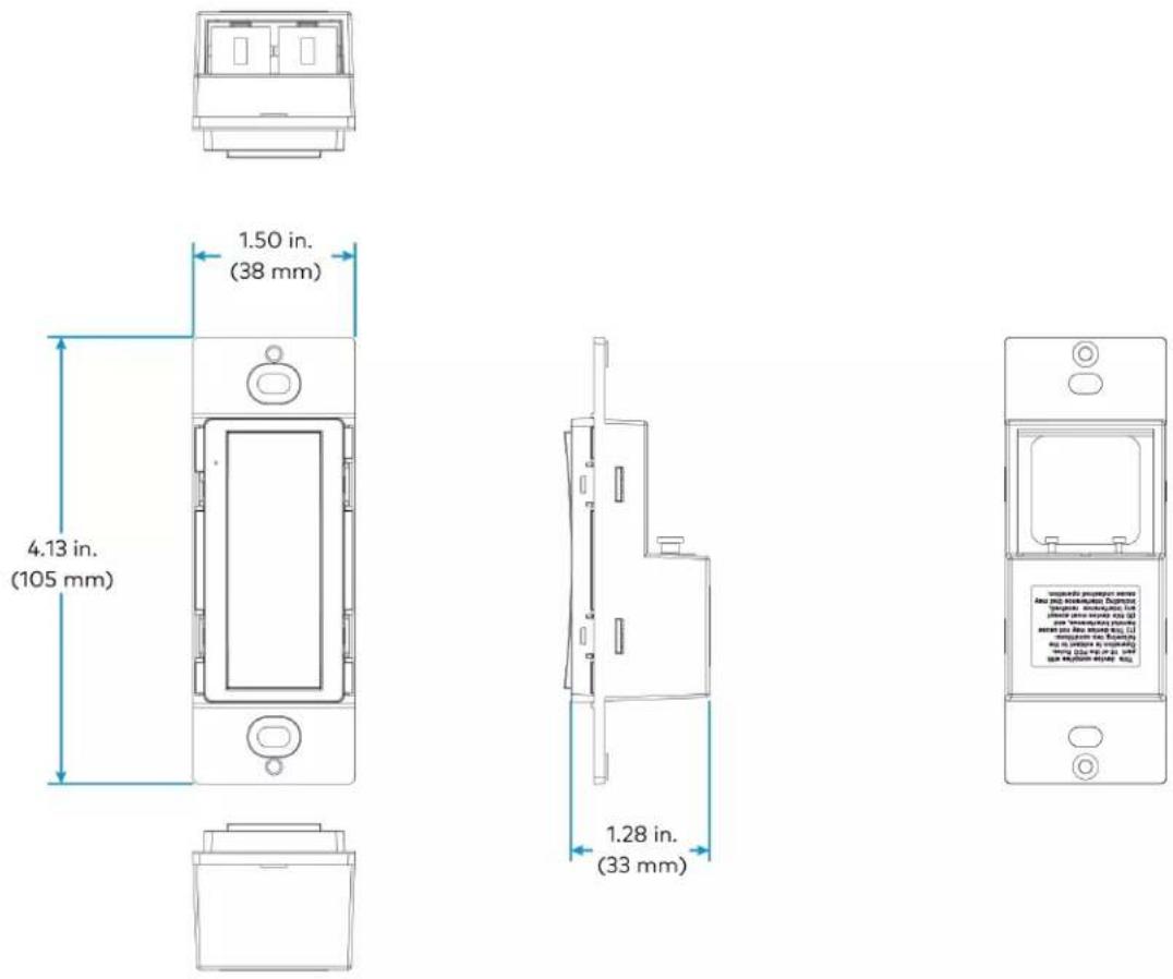
| Mounting Mounts in a 1-gang, 3.5 in. (89 mm) deep electrical box (not supplied) | |
| Faceplate | Requires a decorator style faceplate (FP-G Series, not supplied) |
Dimensions
| Height | 4.13 in. (105 mm) |
| Width | 1.50 in. (38 mm) |
| Depth | 1.28 in. (33 mm) |
Weight
5 oz (142 g)
Regulatory Model: M201937001
UL® Listed for US & Canada, IC, FCC Part 15 Class B digital device, UL 916, CSA C22.2 No. 205, CEC Title 24, ASHRAE 90.1, IECC
Dimension Drawings
Presence Detector Specifications
Product specifications for the Züm Link Presence Detectors are provided below.
Product Specifications
ZUMLINK-IR-QUATTRO-DLS/ ZUMLINK-IR-QUATTRO-DLS-RLY
Power Rating 18 - 24VDC/VAC (14 mA)
Control Output 1A @ 30VAC/VDC
Sensing Passive Infrared (PIR)
Coverage 360° square mechanically scalable detection zones
Sensors single infrared pyroelectric detector
Detection Zones Presence: Major motion as described by NEMA WD7;
Maximum: 30 x 30 ft (900 sq ft)
Radial: Motion either directly toward or away from the sensor;
Maximum: 30 x 30 ft (900 sq ft)
Tangential: Motion perpendicular to the sensor;
Maximum: 46 x 46 ft (2,116 sq ft)
Light Level Setting 10-1000lux / 1-100 fc
Dimensions Height: 4.73 in. (121 mm)
Width: 4.73 in. (121 mm)
Depth: 3.03 in. (77 mm)
ZUMLINK-IR-QUATTRO-HD-DLS/ ZUMLINK-IR-QUATTRO-HD-DLS-RLY
Power Rating 18 - 24VDC/VAC (14 mA)
Control Output 1A @ 30VAC/VDC
Sensing Extremely high definition Passive Infrared (PIR)
Coverage 360° square mechanically scalable detection zones
Sensors 4 infrared pyroelectric detectors
Detection Zones Presence: Major motion as described by NEMA WD7;
Maximum: 50 x 50 ft (2,500 sq ft)/
15 x 15. m (225 sq m)
Light Level Setting 10-1000lux / 1-100 fc
Dimensions Height: 4.73 in. (121 mm)
Width: 4.73 in. (121 mm)
Depth: 2.82 in. (72 mm)
Power Rating 18 - 24VDC/VAC (22 mA)
Control Output 1A @ 30VAC/VDC
Sensing Passive Infrared (PIR) and ultrasonic (40 kHz)
Coverage 360°
Sensors Single infrared pyroelectric detector
Detection Zones Presence: Major motion as described by NEMA WD7;
PIR: Maximum: 50 x 40 ft (2,000 sq ft)/
15 x 12 m (180 sq m);
US: Maximum: 40 x 30 fct (1,200 sq ft)/
12 x 9 m (108 sq m)
Light Level Setting 10-1000lux / 1-100 fc
Dimensions Height: 4.73 in. (121 mm)
Width: 4.73 in. (121 mm)
Depth: 2.63 in. (67 mm)
ZUMLINK-US-HALLWAY-DLS/ ZUMLINK-US-HALLWAY-DLS-RLY
Power Rating 18 - 24VDC/VAC (22 mA)
Control Output 1A @ 30VAC/VDC
Sensing Bidirectional ultrasonic (40 kHz)
Coverage 6.5 x 65 ft linear
Ultrasonic Detection Maximum: 50 x 20 ft (1,000 sq ft)/
15 x 6 m (90 sq m)
Minimum: 40 x 20 ft (800 sq ft)/
12 x 6 m (72 sq m)
Light Level Setting 10-1000lux / 1-100 fc
Dimensions Height: 4.73 in. (121 mm)
Width: 4.73 in. (121 mm)
Depth: 2.84 in. (72 mm)
Power Rating 18 - 24VDC/VAC (22 mA)
Control Output 1A @ 30VAC/VDC
Sensing Unidirectional ultrasonic (40 kHz) occupancy sensor
Coverage 6.5 x 35 ft linear
Ultrasonic Detection Maximum: 35 x 20 ft (700 sq ft)/
11 x 6 m (66 sq m)
Minimum: 25 x 20 ft (50 sq ft)/
8 x 6 m (48 sq m)
Light Level Setting 10-1000lux / 1-100 fc
Dimensions Height: 4.73 in. (121 mm)
Width: 4.73 in. (121 mm)
Depth: 2.84 in. (72 mm)
ZUMLINK-US-QUATTRO-DLS/ ZUMLINK-US-QUATTRO-DLS-RLY
Power Rating 18 - 24VDC/VAC (22 mA)
Control Output 1A @ 30VAC/VDC
Sensing Omnidirectional ultrasonic (40 kHz) presence detection
Coverage 360°
Detection Zones Presence: Major motion as described by NEMA WD7;
Maximum: 40 x 50 ft (2,000 sq ft)/
12 x 15 m (180 sq m)
Light Level Setting 10-1000lux / 1-100 fc
Dimensions Height: 4.73 in. (121 mm)
Width: 4.73 in. (121 mm)
Depth: 2.67 in. (68 mm)
Controls & Indicators
LED (3) Blue LEDs on the sensor head frontplate
Flashes upon start up and when triggered to identify itself
Connections
ZUMLINK (2) RJ-45 orange ports;
In-room Zūm Link device daisy-chaining
Output Relays
(1) Green: Normally open
(Relay models only)
(1) Blue: Normally closed
(1) Red: Common
Environmental
Temperature 32° to 104°F (0° to 40°C)
Rating IP20 rated
Enclosure
Material Plastic
Mounting Mount directly in the ceiling, 4 in. square or round junction boxes (not included), or 3 in. mud rings (not included)
Compliance
Regulatory Mode: M202111001, M202111002, M202111003, and M202111004
UL ^® Listed
Dimension Drawings
ZUMLINK-IR-QUATTRO-DLS and ZUMLINK-IR-QUATTRO-DLS-RLY
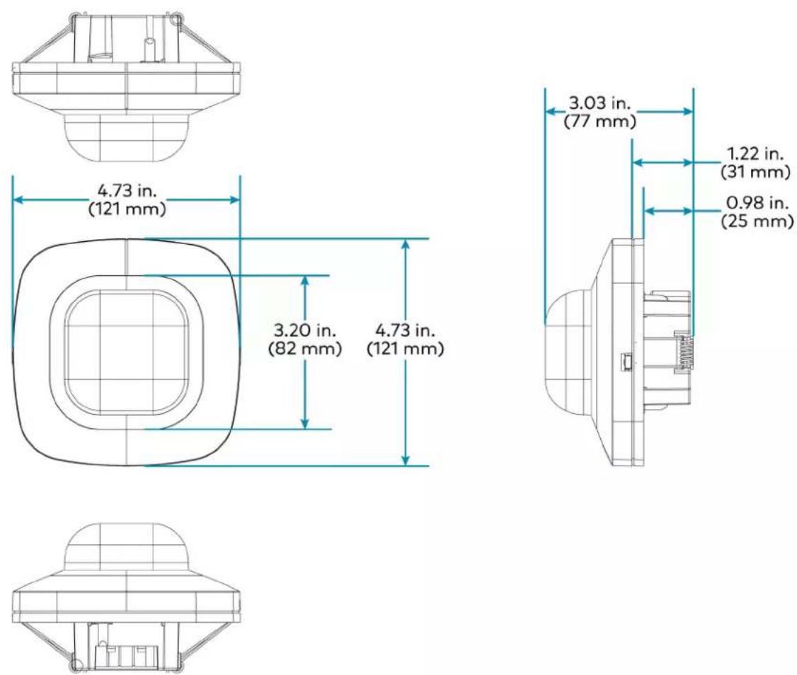


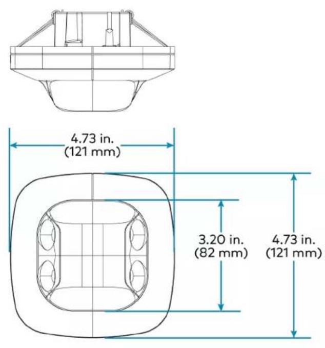
text_image
4.73 in. (121 mm) 3.20 in. (82 mm) 4.73 in. (121 mm)
text_image
2.84 in. (73 mm) 1.22 in. (31 mm) 0.98 in. (25 mm)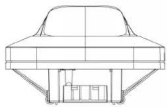
natural_image
Technical line drawing of a car roof structure with support pillars (no text or symbols)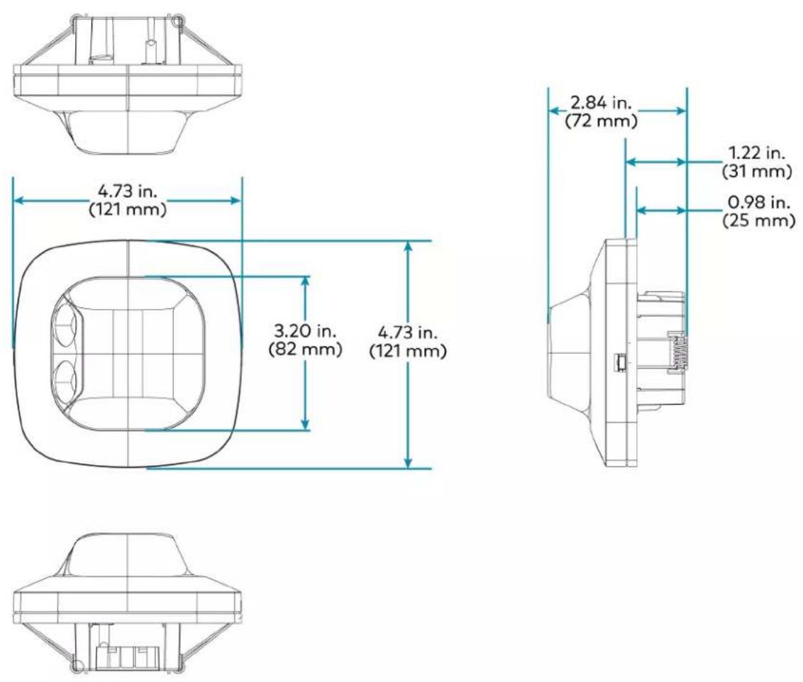

Hub Specifications
The ZUM-HUB4 is featured in three kits.
• ZUML-HUB4-GW Specifications on page 76
• ZUML-HUB4-PAK Specifications on page 77
• ZUML-HUB4-CN-PAK Specifications on page 79
ZUM-HUB4 Specifications
Device Support and Time Clock
| Rooms 1,000 maximum; | |
| Zūm wired, Zūm wireless, and external | |
| External Rooms and Mirrored Rooms | Varies by control system based on hardware capabilities and program complexity of the external processor |
Communications
| Ethernet 10/100/1000 Mbps, auto-switching, auto-negotiating, auto-discovery, full/half duplex, industry-standard TCP/IP stack, UDP/IP, CIP, DHCP, SSL, TLS, SSH, SFTP (SSH File Transfer Protocol), FIPS 140-2 compliant encryption, IEEE 802.1X, SNMP, IPv4 or IPv6, Active Directory® authentication, IIS v.6.0 web server |
| Control Subnet 10/100/1000 Mbps Ethernet, auto-switching, auto-negotiating, auto-discovery, full/half duplex, DHCP server, DNS Server, port forwarding, isolation mode |
| USB Supports computer console via front panel USB 2.0 device port |
Connectors and Card Slots
| MEMORY (1) SD memory card slot; |
| Accepts one 32 GB SD or SDHC card to enable logging and for troubleshooting purposes |
USB (1) USB Type A connector, female;
USB 2.0 host port;
For firmware upgrades
LAN (1) 8-pin RJ-45 connector, female;
10Base-T/100Base-TX/1000Base-T Ethernet port;
Connects to the customer's LAN
CONTROL SUBNET (1) 8-pin RJ-45 connector, female;
10Base-T/100Base-TX/1000Base-T Ethernet port;
Provides a dedicated local network for Zūm Net wireless gateways and wired rooms
NET (1) 4-pin 3.5mm detachable terminal block; Connects to a GLS-SIM which facilitate Demand Response when connected to a nonsystem sensor, such as a GLS-ODT-C-NS; Not used for power
24VDC 2.0A (1) 2.1 x 5.5 mm DC power connector; 24VDC power input; PW-2420RU power pack included
G (1) 6-32 screw; Chassis ground lug COMPUTER (front) (1) USB Type B connector, female; USB 2.0 device port for configuration via computer console (cable included)
Controls & Indicators
PWR (1) Green LED; Indicates operating power supplied from the included power pack NET (1) Amber LED; Not used
MSG (1) Red LED; Indicates that the ZUM-HUB4 has generated an error message
HW-R (1) Recessed pushbutton for hardware reset
SW-R (1) Recessed pushbutton for software reset
LAN (rear) (2) Bi-color green/amber LEDs; Left LED indicates Ethernet link status and connection speed; Right LED indicates Ethernet activity
CONTROL SUBNET (2) Bi-color green/amber LEDs; (rear) Left LED indicates Ethernet link status and connection speed; Right LED indicates Ethernet activity
Power
Power Pack (included) Input: 100-240VAC, 50/60 Hz; Output: 2.5A @ 24VDC Model: PW-2420RU
Power Consumption 15 W
Environmental
Temperature 41° to 113°F (5° to 45°C) Humidity 10% to 90% RH (noncondensing) Heat Dissipation 50 BTU/hr
Enclosure
Chassis Metal, black finish Faceplate Extruded metal, black finish, polycarbonate label overlay Mounting Freestanding or 1 RU 19-inch rack-mountable; Adhesive feet and rack ears included
Dimensions
Height 1.70 in. (43 mm) without feet
Width 17.28 in. (439 mm);
19.00 in. (482 mm) with rack ears
Depth 6.47 in. (165 mm)
Weight
3.1 lb (1.42 kg)
Compliance
Regulatory Model: M201903003
UL® Listed for US & Canada, IC, CE, FCC Part 15 Class B digital device, UL 916, CEC Title 24, ASHRAE 90.1, IECC
ZUM-HUB4 Dimension Drawings

other
| Dimension | Value | | ----------------- | ------- | | Width (in.) | 17.16 | | Height (in.) | 6.47 | | Total Width (mm) | 17.28 | | Total Height (mm) | 0.19 |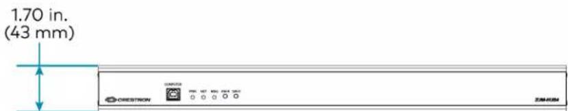
text_image
1.70 in. (43 mm) DRESSRON ZEN-80M
text_image
1.68 in. (43 mm)ZUML-HUB4-GW Specifications
Power
Main Power Input: 100-240VAC, 50/60 Hz; Output: 2.5A @ 24VDC Model: PW-2420RU
Environmental
Temperature 41° to 113°F (5° to 45°C) Humidity 10% to 90% RH (non-condensing)
Dimensions
Height 1.70 in. (43 mm) without feet Width 17.28 in. (439 mm); 19.00 in. (482 mm) with rack ears
Depth 6.47 in. (165 mm)
ZUML-HUB4-GW Dimension Drawings
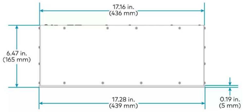
other
| Segment Width (in.) | Total Width (mm) | | ------------------- | ---------------- | | Top Left | 17.16 | | Top Right | 17.28 | | Bottom Left | 6.47 | | Bottom Right | 0.19 |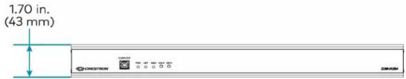
text_image
1.70 in. (43 mm) DRESSRON PRO. SET MDD NET 100 ZIMUSH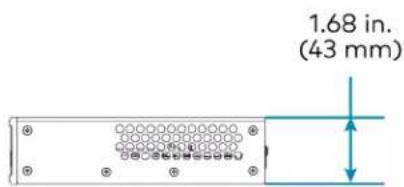
text_image
1.68 in. (43 mm)ZUML-HUB4-PAK Specifications
Power
Main Power 120VAC, 60 Hz
Environmental
Temperature 41° to 104°F (5° to 40°C)
Humidity 10% to 90% RH (non-condensing)
Dimensions
Height 24.25 in. (616 mm)
Width 15.13 in. (384 mm)
Depth 4.19 in. (107 mm)
Compliance
CE, UL® Listed
Crestron Züm® Wired Lighting Control systems fully assembled in Crestron's UL certified panel shop are UL508 Listed.
Assembly
Crestron Zūm® Wired Lighting Control systems fully assembled in Crestron's UL certified panel shop are UL508 Listed. The individual components may also be ordered and shipped unassembled, requiring on-site assembly and any applicable certifications and inspections.
ZUML-HUB4-PAK Dimension Drawings
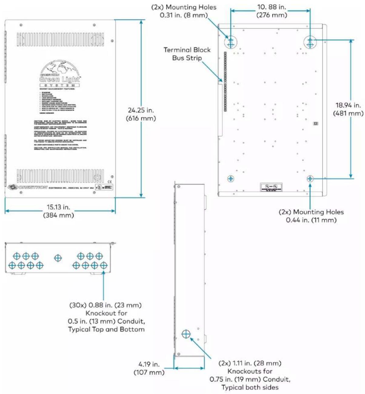
text_image
(2x) Mounting Holes 0.31 in. (8 mm) 10. 88 in. (276 mm) Terminal Block Bus Strip 18.94 in. (481 mm) 24.25 in. (616 mm) 15.13 in. (384 mm) (30x) 0.88 in. (23 mm) Knockout for 0.5 in. (13 mm) Conduit, Typical Top and Bottom 4.19 in. (107 mm) (2x) 1.11 in. (28 mm) Knockouts for 0.75 in. (19 mm) Conduit, Typical both sidesZUML-HUB4-CN-PAK Specifications
Power
Main Power 120VAC, 60 Hz
Environmental
Temperature 41° to 104°F (5° to 40°C)
Humidity 10% to 90% RH (non-condensing)
Dimensions
Height 39.63 in. (1,007 mm)
Width 16.13 in. (409 mm)
Depth 4.44 in. (113 mm)
ZUML-HUB4-CN-PAK Dimension Drawings

text_image
39.63 in. (1007 mm) 16.13 in. (409 mm)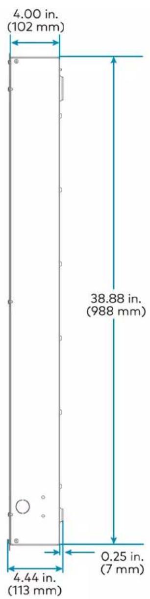
text_image
4.00 in. (102 mm) 38.88 in. (988 mm) 4.44 in. (113 mm) 0.25 in. (7 mm)-
SIMPL+® software modules are provided for use in commissioning a Crestron control system to work with the ZUM-HUB4. The software modules run within the control system program and provide virtual connections for all the necessary intersystem control signals. A separate dedicated module is required for each external and mirrored room. Control systems are limited in the number of modules supported, ranging from 0 to 2001000 depending on the model. For further assistance, please contact Crestron Commercial Lighting Support via email at clclighting@crestron.com or by calling 855-644-7643.
-
Other Crestron control systems must be commissioned to provide the control logic required to communicate and operate as part of the Züm network. Once integrated, each external room effectively becomes a part of the Züm ecosystem.
Zūm App Specifications
Specifications for the Zūm app are provided below.
Compatible Devices
Apple iOS Requires Apple iOS 14.0 or later
Android Requires Android OS 7.0 or later
Communications
Bluetooth Bluetooth low energy, Version 4.0;
Pairs with a compatible Zūm device
Cable Specifications
Cables are available for Zūm Net and Zūm Link applications.
• CBL-CAT5E-ZUMNET-P Specifications on page 84
• CBL-CAT5E-ZUMLINK-P Specifications on page 85
CBL-CAT5E-ZUMNET-P Specifications
Cable
Terminations (2) RJ-45 connectors;
(1) connector per end with dust cap
NOTE: RJ-45 connectors and dust caps are not included with the CBL-CAT5E-ZUMNET-P-SP500.
Unshielded Twisted
Colors: Blue/white, orange/white, green/white, brown/white;
Pairs
Conductors: 24 AWG solid copper
Insulation: FEP, 0.005 in. nominal thickness
(4)
Outer Jacket Color: Purple;
Material: Low smoke PVC
Lengths CBL-CAT5E-ZUMNET-P-25: 25 ft (8 m)
CBL-CAT5E-ZUMNET-P-50: 50 ft (15 m)
CBL-CAT5E-ZUMNET-P-100: 100 ft (30 m)
CBL-CAT5E-ZUMNET-P-SP500: 500 ft (152 m) spool
CBL-CAT5E-ZUMNET-P Dimension Drawings

text_image
.56 in. (14 mm) .42 in. (11 mm) RJ-45 (2)CBL-CAT5E-ZUMLINK-P Specifications
Cable
Power Provides 24V power to Zūm Link devices
Terminations (2) RJ-45 connectors;
NOTE: RJ-45 connectors are not included with the CBL-CAT5E-ZUMLINK-P-SP500.
Unshielded Twisted
Colors: Blue/white, orange/white, green/white, brown/white;
Pairs
Conductors: 24 AWG solid copper
Insulation: FEP, 0.005 in. nominal thickness
(4)
Outer Jacket Color: Orange;
Material: Low smoke PVC
Lengths CBL-CAT5E-ZUMLINK-P-0.5: 6 in. (152 mm)
CBL-CAT5E-ZUMLINK-P-3: 3 ft (0.9 m)
CBL-CAT5E-ZUMLINK-P-6: 6 ft (2 m)
CBL-CAT5E-ZUMLINK-P-12: 12 ft (4 m)
CBL-CAT5E-ZUMLINK-P-25: 25 ft (8 m)
CBL-CAT5E-ZUMLINK-P-50: 50 ft (15 m)
CBL-CAT5E-ZUMLINK-P-12-10PK: 12 ft (4 m), 10 pack
CBL-CAT5E-ZUMLINK-P-25-10PK: 25 ft (8 m), 10 pack
CBL-CAT5E-ZUMLINK-P-SP500: 500 ft (152 m) spool
CBL-CAT5E-ZUMLINK-P Dimension Drawings
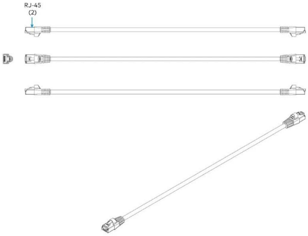
text_image
RJ-45 (2)Cable Accessory Specifications
Cables accessories include the ZUMLINK-CONV-CN adapter cable and the ZUMLINK-SPLTR-RJ45 splitter.
• ZUMLINK-CONV-CN Product Specifications on page 87
• ZUMLINK-SPLTR-RJ45 Product Specifications on page 88
ZUMLINK-CONV-CN Product Specifications
Connectors
Cresnet Terminal Block (1) 4-pin captive screw terminal block;
24: 24V power
Y: Data terminal pass-through only
Z: Data terminal pass-through only
G: Ground
Emergency Override (1) 4-pin captive screw terminal block;
Terminal Block 24: 24V power
O: Emergency override
W: Future use
G: Ground
ZUM LINK RJ-45 (1) female RJ-45 Zūm Link port
Construction
Conductors 24 AWG solid copper
Insulation FEP, 0.005 in. nominal thickness
Outer Jacket Color: Orange;
plenum rated
Dimensions
Cable length 6 in. (152 mm), excluding the connectors
ZUMLINK-CONV-CN Dimension Drawings
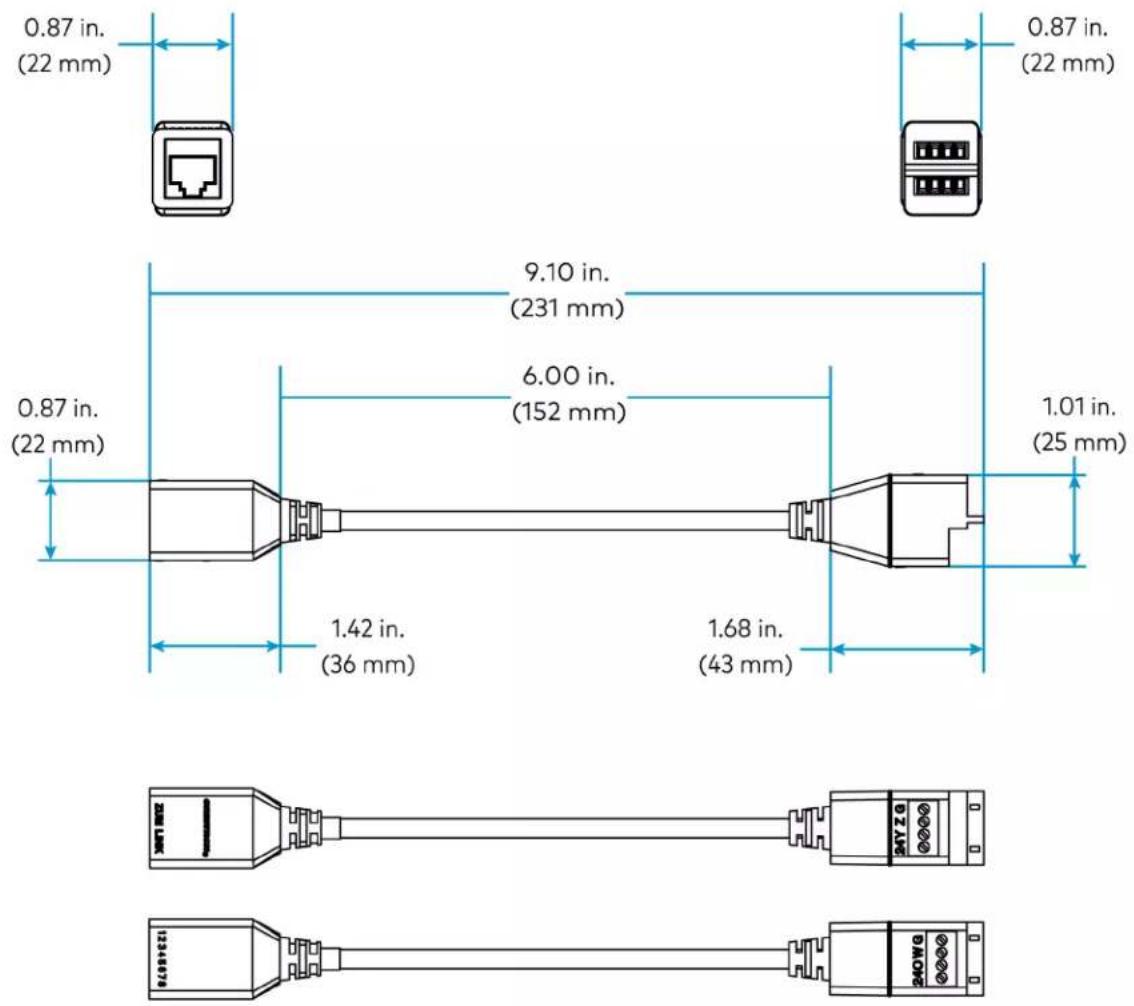
ZUMLINK-SPLTR-RJ45 Product Specifications
Connectors
ZUM LINK (3) female RJ-45 Zūm Link connectors
Dimensions
Height 0.87 in. (22 mm)
Width 0.91 in. (23 mm)
Depth 1.34 in. (34 mm)
ZUMLINK-SPLTR-RJ45 Dimension Drawings
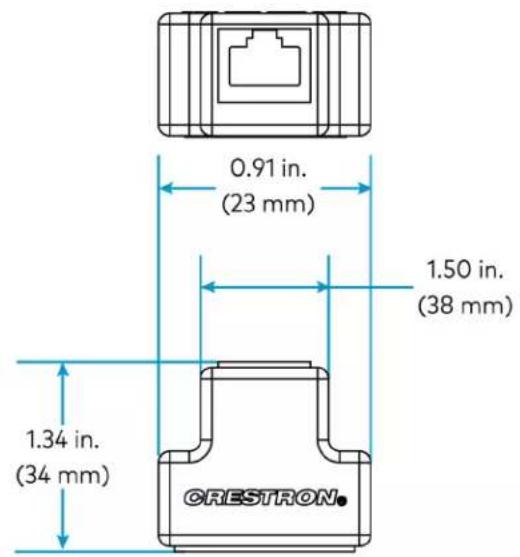
text_image
0.91 in. (23 mm) 1.50 in. (38 mm) 1.34 in. (34 mm) CRESTRON.
text_image
0.87 in. (22 mm)Power Supply Specifications
Product specifications for the ZUMLINK-JBOX-PSU are provided below.
Product Specifications
Power Requirements
| AC Input Power 100-277VAC, 50/60 Hz | |
| Züm Link Output | 250mA per segment; |
| Current | 500mA total across both segments(4 ports);Segment 1: ports 1 and 2Segment 2: ports 3 and 4 |
| Züm Link Pass-through | 250mA max; |
| Current | Including internal power supply: 750mA cumulative maximum |
Wired Communications
| ZUMLINK (4) RJ-45 ports |
| Controls and Indicators |
| PWR Status (1) green LED;Power indicator |
Connections
| Hot (1) 14 AWG Class 1 flying lead;Black, line power input |
| Neutral (1) 14 AWG Class 1 flying lead;White, neutral |
Environmental
| Rating IP20 |
| Temperature 32° to 104°F (0° to 40°C) |
Construction
| Housing Plastic, white, UL 94 5VA flame rated |
| Mounting Mounts to the side of a 4 in. square junction box via a 1/2 in. conduit knockout;Meets the requirements of UL 2043 for installation in an environmental air-handling (plenum) space |
Dimensions
| Height | 4.93 in. (125 mm) |
| Width | 4.25 in. (108 mm) |
Depth 2.03 in. (52 mm)
Weight
7 oz (199 g)
Compliance
Regulatory Model: M202107003
cUL916, cUL2043
UL® Listed for US & Canada, IC, FCC Part 15 Class A digital device, UL 916, UL 2043, UL 94 5VA
Dimension Drawings

Rocker and Button Tree Specifications
Product specifications for the rocker and button tree configurations are provided below.
Product Specifications
Environmental
Temperature 32° to 104°F (0° to 40°C)
Humidity 10% to 90% RH (noncondensing)
Construction
Composition Plastic
Dimensions
Height 2.62 in. (67 mm)
Width 1.30 in. (33 mm)
Depth Rocker: 0.46 in. (12 mm)
2, 4, 6, and 8 button trees: 0.47 in. (12 mm)
Weight
-0.2 oz (6.4 g)
Dimension Drawings
ZUMLINK-BTNR (BLANK shown)

ZUMLINK-BTN2 (BLANK shown)
ZUMLINK-BTN4 (BLANK shown)
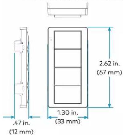
text_image
.47 in. (12 mm) 1.30 in. (33 mm) 2.62 in. (67 mm)ZUMLINK-BTN6 (BLANK shown)
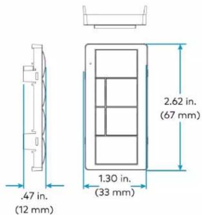
text_image
.47 in. (12 mm) 1.30 in. (33 mm) 2.62 in. (67 mm)ZUMLINK-BTN8 (BLANK shown)

text_image
.47 in. (12 mm) 1.30 in. (33 mm) 2.62 in. (67 mm)Installation
Refer to the following sections for instructions on how to install the various Zūm Wired models.
- Load Controller Installation
• Universal Dimmer Load Controller Installation - Keypad Installation
• Presence Detectors Installation - Hub Installation
• Cable Accessory Installation
• Power Supply Installation - Rocker and Button Tree Installation
Load Controller Installation
The Züm Net and Züm Link junction box load controllers mount directly to a 4 in. square junction box (not included) and connects to other Züm devices via CBL-CAT5E-ZUMLINK-P or CBL-CAT5E-ZUMNET-P cables (sold separately, refer to Cables on page 14). For installing the universal dimmer load controller, refer to Universal Dimmer Load Controller Installation on page 104.
NOTES:
- Zūm Net load controllers facilitate communications between rooms via CBL-CAT5E-ZUMNET-P cables (sold separately) and can be daisy-chained for network expansion. Zūm Link devices connect to ZUMNET-JBOX devices to provide in-room lighting control
- Zūm Link load controllers allow for in-room lighting control through compatible keypads and sensors. Two RJ-45 ports on the device and the CBL-CAT5E-ZUMLINK-P cables (sold separately) allow for connection to a Zūm Net device and for in-room device daisy-chaining.
In the Box
Qty. Description
| 1 ZUMNET-JBOX-16A-LV, ZUMNET-JBOX-DALI, ZUMLINK-JBOX-16A-LV,ZUMLINK-JBOX-20A-PLUG, or ZUMLINK-JBOX-20A-SW Wired J-Box Load Controller |
| Additional Items |
| 5 Yellow Wire Nut, 22-10 AWG (2049245) |
| 1 Locknut (2047626) |
| 1 Tie Wrap (2005429) |
Install the Load Controller
WARNINGS:
- To avoid fire, shock, or death, turn off the power at the circuit breaker or fuse and test that the power is off before wiring!
- Do NOT connect standard Ethernet ports on network-based devices to the orange Zūm Link ports on any Zūm Link or Zūm Net device. Also, do NOT connect the purple Zūm Net ports on the Zūm Net device to the orange Zūm Link ports on any Zūm Link device. These connections may damage network devices.

text_image
Zūm Link cable (orange) Zūm Net load controller Zūm Net cable (purple)NOTES:
• Install and use this product in accordance with appropriate electrical codes and regulations.
• A licensed electrician should install this product.
• The product should project 4.40 in. (112 mm) from the junction box when installed.
- For use where temperatures are between 32^ to 104^ F (0° to 40°C)
- For Chicago plenum compliant installations:
- Ensure that the junction boxes and other electrical components are rated for Chicago plenum.
Separate the high-voltage lines from the low-voltage cables.
• Install two junction boxes: one junction box for the high-voltage lines and one junction box for the low-voltage cables and load controller. A 6 in. square, 3.5 in. deep box with conduit knockouts is recommended for the low-voltage cables and load controller.
To install a load controller:
- Turn the power off at the circuit breaker.
- Mount the load controller to the junction box using the included locknut.
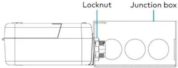
text_image
Locknut Junction box- Wire the load controller as shown in the following diagrams.
Zūm Net Load Controller Wiring to Other Zūm Net and Zūm Link Devices

text_image
ZUMLINK (2): (orange) To Züm Link devices ZUMLINK (ROOM) 24V O D OVR ZUMNET (LAN) ZUMNET (2): (purple) To Züm Net devices 24V: Power for occupancy sensor and daylight sensor OCC: To occupancy sensor GND: To ground PHO: To photosensor OVR: To override inputZUMNET-JBOX-DALI Wiring

text_image
100-277VAC power from breaker Neutral (=white) Hot (—black) To DALI controlled load Nonswitched power monitoring output (red —) DALI input/ output (purple —) DALI input/ output (gray —) To Zūm Link devices (orange) To non-system sensor To Zūm Net devices (purple)ZUMNET-JBOX-DALI Wiring to Meet Chicago Electric Code
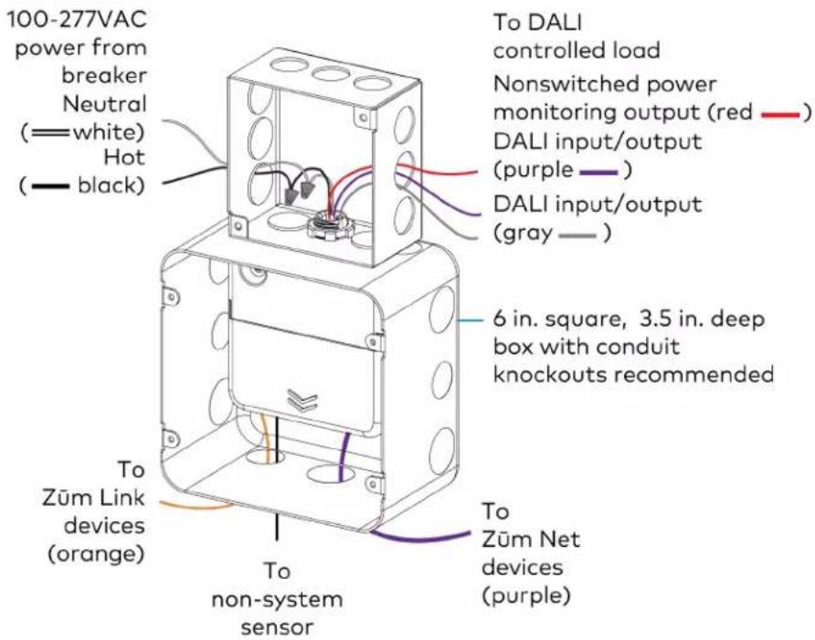
text_image
100-277VAC power from breaker Neutral (=white) Hot (—black) To DALI controlled load Nonswitched power monitoring output (red —) DALI input/output (purple —) DALI input/output (gray —) 6 in. square, 3.5 in. deep box with conduit knockouts recommended To Zūm Link devices (orange) To non-system sensor To Zūm Net devices (purple)ZUMNET-JBOX-16A-LV Wiring

text_image
100-277VAC power from breaker Neutral (=white) Hot (—black) To 0-10V controlled load Neutral (white =)— Switched output (red —) 0-10V dim + (purple —) 0-10V dim - (pink —) To Zūm Link devices (orange) To non-system sensor To Zūm Net devices (purple)ZUMNET-JBOX-16A-LV Wiring to Meet Chicago Electric Code
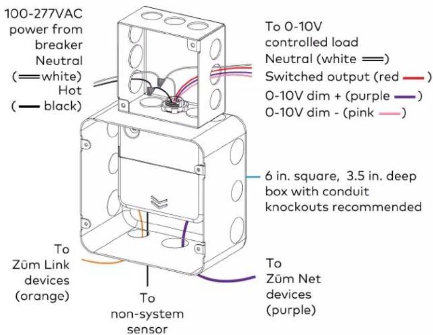
text_image
100-277VAC power from breaker Neutral (=white) Hot (—black) To 0-10V controlled load Neutral (white =)— Switched output (red —) 0-10V dim + (purple —) 0-10V dim - (pink —) 6 in. square, 3.5 in. deep box with conduit knockouts recommended To Zūm Link devices (orange) To non-system sensor To Zūm Net devices (purple)Zūm Link Load Controller Wiring to Other Zūm Link Devices

text_image
ZUMLINK (2): (orange) To Zūm Link devices ZUMLINK (ROOM) 24V 0.0VR 24V OCC GND 24V PHO GND OVR GND 24V: Power for occupancy sensor and daylight sensor OCC: To occupancy sensor GND: To ground PHO: To photosensor OVR: To override inputZūm Link Load Controller Wiring
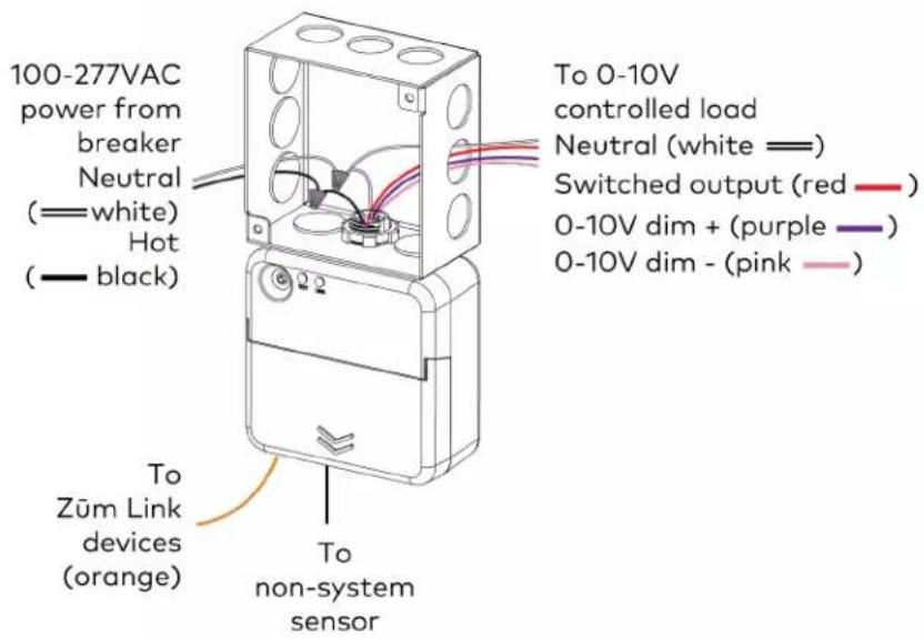
text_image
100-277VAC power from breaker Neutral (=white) Hot (—black) To Zūm Link devices (orange) To non-system sensor To 0-10V controlled load Neutral (white =)— Switched output (red —) 0-10V dim + (purple —) 0-10V dim - (pink —)Züm Link Load Controller Wiring to Meet Chicago Electric Code
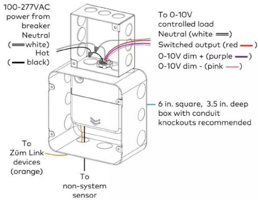
text_image
100-277VAC power from breaker Neutral (=white) Hot (—black) To 0-10V controlled load Neutral (white =)— Switched output (red —) 0-10V dim + (purple —) 0-10V dim - (pink —) 6 in. square, 3.5 in. deep box with conduit knockouts recommended To Züm Link devices (orange) To non-system sensorZüm Wired System Diagram

flowchart
graph TD
    subgraph Room 1
        A["Züm Link Presence detector"] --> B["Züm Link power supply"]
        B --> C["Züm Link Presence detector"]
        C --> D["Non-system sensor"]
        D --> E["Züm Link load controller"]
        E --> F["Züm Link keypad"]
        G["Control system"] --> H["Network switch"]
        I["Room 2"] --> J["Züm Link universal dimmer"]
        J --> K["Züm Link Presence detector"]
        K --> L["Züm Link presence detector"]
        L --> M["Züm Link load controller"]
        M --> N["Züm Link keypad"]
        O["To next room (up to 20 devices)"] --> P["Züm Net (room-to-room control)"]
        Q["Züm Link (in-room control)"] --> R["Züm Link"]
        S["SW or LV control"] --> T["Züm Link"]
    end
    subgraph Room 2
        U["Züm Link universal dimmer"] --> V["Züm Link Presence detector"]
        V --> W["Züm Link presence detector"]
        W --> X["Züm Link load controller"]
        X --> Y["Züm Link keypad"]
        Z["To next room (up to 20 devices)"] --> AA["Züm Net (room-to-room control)"]
        AB["24VDC control"] --> AC["Züm Link (in-room control)"]
        AD["SW or LV control"] --> AE["Züm Link"]
NOTES:
- Daisy-chain up to 20 Züm Net devices (up to 328 ft (100 m) between Züm Net devices) with purple CBL-CAT5E-ZUMNET-P RJ-45 cables (sold separately).
- Do not exceed three network switches between a ZUM-HUB4 and a Zūm Net device.
- System sensors communicate digitally via Zūm Link. Non-system sensors communicate via an analog connection on a Zūm Wired load controller.
Test the Loads
To verify system wiring, test the loads. Tap the TEST button to turn the connected loads on and off. Press and hold the TEST button to cycle the connected dimmers.
Züm Link Load Controllers

text_image
Recessed test button TEST and LINK LEDs TEST LINKZüm Net Load Controllers

text_image
Recessed test button TEST, LINK, and NET LEDs TEST LINK NETFor more information, refer to the following topics:
- Load Controller Operation on page 148
• Zūm App Configuration on page 158
Universal Dimmer Load Controller Installation
The Crestron Zūm® Wired Lighting Control is a single-channel universal dimmer load controller designed to control a wide range of dimmable lighting load types. Using proprietary zero-cross filter technology, the Crestron Zūm® Wired Lighting Control provides superior immunity to power line noise, resulting in a significant reduction of lamp flicker.
Energy-saving options (sold separately) are available to enable daylighting, occupancy or vacancy sensing, integration, and centralized monitoring and management.
In the Box
Qty. Description
1 ZUMLINK-EXP-16A-DIMU, Züm® Wired Universal Dimmer Load Controller
Additional Items
1 Bushing, Open/Closed, 0.94 in. ID x 1.23 in. OD, Black (2060645)
Important Safeguards
CAUTION: When using electrical equipment, basic safety precautions should always be followed:
- Read and follow all safety instructions.
- Do not mount near gas or electric heaters.
- Equipment should be mounted in locations and at heights where it will not readily be subjected to tampering by unauthorized personnel.
- The use of accessory equipment not recommended by the manufacturer may cause an unsafe condition.
- Save these instructions.
Install the Universal Dimmer Load Controller
Install the ZUMLINK-EXP-16A-DIMU on any vertical surface using four screws (not included). The screws must be appropriate for the mounting surface.
WARNINGS:
- To avoid fire, shock, or death, turn off the power at the circuit breaker or fuse and test that the power is off before wiring!
- Do NOT connect standard Ethernet ports on network-based devices to the orange Zūm Link ports on any Zūm Link or Zūm Net device. Also, do NOT connect the purple Zūm Net ports on the Zūm Net device to the orange Zūm Link ports on any Zūm Link device. These connections may damage network devices.

text_image
Zūm Net cable (purple) Zūm Link universal dimmer Zūm Net load controller Zūm Link cable (orange)CAUTION: To prevent heat damage to drywall, secure a 1/2 in. (13 mm) thick piece of plywood to the wall and then secure the ZUMLINK-EXP-16A-DIMU to the plywood.
NOTES:
• Install and use this product in accordance with appropriate electrical codes and regulations.
• A licensed electrician should install this product.
- Use copper wire rated 75^ (167°F) or better.
- Suitable for damp locations
- For use where temperatures are between 32^ to 104^ F ( 0^ to 40^ C )
Wiring the Universal Dimmer Load Controller
WARNING: RISK OF SERIOUS PERSONAL INJURY. To avoid fire, shock, or death, turn off the power at the circuit breaker(s) or fuse and test that power is off before installing and wiring! Installing with power on can result in serious personal injury and damage to the device.
- Turn the power off at the circuit breaker.
- Insert the included bushing into the knockout hole to protect the low voltage wires.
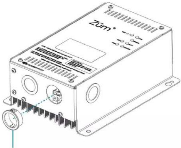
text_image
Zum®Insert included bushing
- Use a #2 Phillips screwdriver to remove the cover screws and then remove the cover.
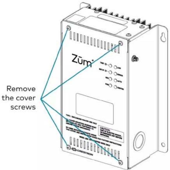
text_image
Zūm® Remove the cover screws TYPE 1: MEDIUM POWER ON OUT CUSTO OF ELECTRIC CONTROL FOR HEAVING UHVDC POWER POWER NO. FOR VOLTAGE SWITCH WEATHER BY: ZUMER WEATHER BY: ZUMER CRESTRON-
Wire the device as shown below. Additional LINE, NEUT, and GND connections are supplied for power pass-through. When making connections, consider the following:
-
Wires should be 24 to 10 AWG.
- Strip wires to 5/16 in. (8 mm).
- Tighten screw terminals to 4.5 in.-lbs (0.5 Nm).

text_image
NEUT NEUT NEUT LINE DIM From circuit breaker or fuse panel Pass-through to additional modules To dimmed loads To ground To Zūm Link devices (orange)- Connect the orange CBL-CAT5E-ZUMLINK-P (sold separately) to the ZUMLINK ports.
Zūm Wired System Diagram
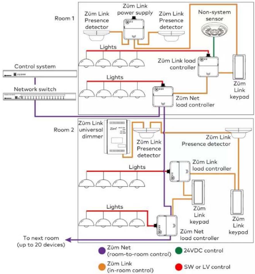
flowchart
graph TD
    subgraph Room 1
        A["Züm Link Presence detector"] --> B["Züm Link power supply"]
        B --> C["Züm Link Presence detector"]
        D["Non-system sensor"] --> E["Züm Link load controller"]
        E --> F["Züm Net load controller"]
        G["Control system"] --> H["Network switch"]
        I["Room 2"] --> J["Züm Link universal dimmer"]
        J --> K["Züm Link Presence detector"]
        K --> L["Züm Link Presence detector"]
        M["Room 2"] --> N["Züm Link universal dimmer"]
        N --> O["Züm Link Presence detector"]
        P["Room 2"] --> Q["Züm Link universal dimmer"]
        Q --> R["Züm Link Presence detector"]
        S["Room 2"] --> T["Züm Link universal dimmer"]
        T --> U["Züm Link Presence detector"]
        V["Room 2"] --> W["Züm Link universal dimmer"]
        W --> X["Züm Link Presence detector"]
        Y["Room 2"] --> Z["Züm Link universal dimmer"]
        Z --> AA["Züm Link Presence detector"]
        AB["Room 2"] --> AC["Züm Link universal dimmer"]
        AC --> AD["Züm Link Presence detector"]
        AE["Room 2"] --> AF["Züm Link universal dimmer"]
        AF --> AG["Züm Link Presence detector"]
        AH["Room 2"] --> AI["Züm Link universal dimmer"]
        AI --> AJ["Züm Link Presence detector"]
        AK["Room 2"] --> AL["Züm Link universal dimmer"]
        AL --> AM["Züm Link Presence detector"]
        AN["Room 2"] --> AO["Züm Link universal dimmer"]
        AO --> AP["Züm Link Presence detector"]
        AQ["Room 2"] --> AR["Züm Link universal dimmer"]
        AR --> AS["Züm Link Presence detector"]
        AT["Room 2"] --> AU["Züm Link universal dimmer"]
        AU --> AV["Züm Link Presence detector"]
        AW["Room 2"] --> AX["Züm Link universal dimmer"]
        AX --> AY["Züm Link Presence detector"]
        AZ["Room 2"] --> BA["Züm Link universal dimmer"]
        BA --> BB["Züm Link Presence detector"]
        BC["Room 2"] --> BD["Züm Link universal dimmer"]
        BD --> BE["Züm Link Presence detector"]
        BF["Room 2"] --> BG["Züm Link universal dimmer"]
        BG --> BH["Züm Link Presence detector"]
        BI["Room 2"] --> BJ["Züm Link universal dimmer"]
        BJ --> BK["Züm Link Presence detector"]
        BL["Room 2"] --> BM["Züm Link universal dimmer"]
        BM --> BN["Züm Link Presence detector"]
        BO["Room 2"] --> BP["Züm Link universal dimmer"]
        BP --> BQ["Züm Link Presence detector"]
        BR["Room 2"] --> BS["Züm Link universal dimmer"]
        BS --> BT["Züm Link Presence detector"]
        BU["Room 2"] --> BV["Züm Link universal dimmer"]
        BV --> BW["Züm Link Presence detector"]
        BX["Room 2"] --> BY["Züm Link universal dimmer"]
        BY --> BZ["Züm Link Presence detector"]
        CA["Room 2"] --> CB["Züm Link universal dimmer"]
        CB --> CC["Züm Link Presence detector"]
        CD["Room 2"] --> CE["Züm Link universal dimmer"]
        CE --> CF["Züm Link Presence detector"]
        CG["Room 2"] --> CH["Züm Link universal dimmer"]
        CH --> CI["Züm Link Presence detector"]
        CJ["Room 2"] --> CK["Züm Link universal dimmer"]
        CK --> CL["Züm Link Presence detector"]
        CM["Room 2"] --> CN["Züm Link universal dimmer"]
        CN --> CO["Züm Link Presence detector"]
        CP["Room 2"] --> CQ["Züm Link universal dimmer"]
        CQ --> CR["Züm Link Presence detector"]
        CS["Room 2"] --> CT["Züm Link universal dimmer"]
        CT --> CU["Züm Link Presence detector"]
        DU["Room 2"] --> DVZ["Züm Link universal dimmer"]
        DVZ --> DW["Züm Link Presence detector"]
        DX["Room 2"] --> DXZ["Züm Link universal dimmer"]
        DXZ --> DXZL["Züm Link Presence detector"]
NOTES:
- Daisy-chain up to 20 Züm Net devices (up to 328 ft (100 m) between Züm Net devices) with purple CBL-CAT5E-ZUMNET-P RJ-45 cables (sold separately).
- Do not exceed three network switches between a ZUM-HUB4 and a Zūm Net device.
- System sensors communicate digitally via Zūm Link. Non-system sensors communicate via an analog connection on a Zūm Wired load controller.
For more information, refer to the following topics:
• Universal Dimmer Load Controller Operation on page 152
• Zūm App Configuration on page 158
Keypad Installation
The ZUMLINK-KP mounts to a standard electrical box. Rocker buttons/button trees and bezels are available in almond, black, gray, red, and white. The button trees also have options for blank buttons, standard pad printed labels, or custom engravings. A finished installation requires a decorator-style faceplate (FP-G series, sold separately).
In the Box
Qty. Description
1 ZUMLINK-KP, Zūm® Wired Keypad with Link Communication, Rocker Button
Additional Items
2 Screw, 6-32 x 3/4 in., Truss Head, Combo (2009211)
Install the Keypad
The ZUMLINK-KP comes preassembled with the white ZUMLINK-BTNR rocker button. If another rocker button or button tree is required, refer to Replace the Rocker Button/Button Tree and Bezel on page 114.
WARNINGS:
- To avoid fire, shock, or death, turn off the power at the circuit breaker or fuse and test that the power is off before wiring! - Do NOT connect standard Ethernet ports on network-based devices to the orange Zūm Link ports on any Zūm Link or Zūm Net device. Also, do NOT connect the purple Zūm Net ports on the Zūm Net device to the orange Zūm Link ports on any Zūm Link device. These connections may damage network devices.

text_image
Zūm Link cable (orange) Zūm Net load controller Zūm Link keypad Zūm Net cable (purple)NOTES:
• Install and use this product in accordance with appropriate electrical codes and regulations.
• A licensed electrician should install this product.
- Ensure that the system power is off until the keypad is fully installed.
- For use where temperatures are between 32^ to 104^ (0° to 40°C)
- Several keypads may be installed in one electrical box (multigang). For a smooth appearance, install one-piece multigang faceplates (not included).
Wire the Keypad
Use orange CBL-CAT5E-ZUMLINK-P cables (sold separately) to wire in-room Züm wired devices, such as load controllers, to the ZUMLINK-KP.
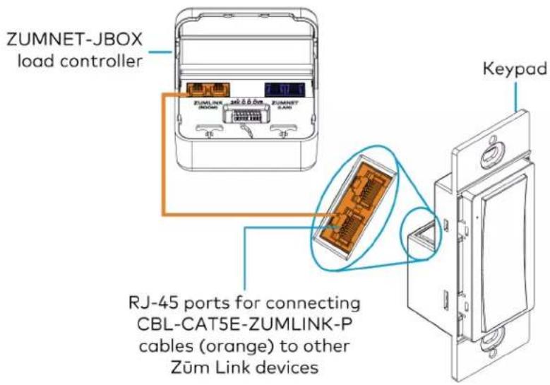
text_image
ZUMNET-JBOX load controller RJ-45 ports for connecting CBL-CAT5E-ZUMLINK-P cables (orange) to other Zūm Link devices KeypadZüm Wired System Diagram
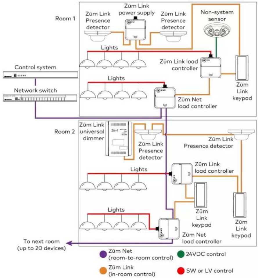
flowchart
graph TD
    subgraph Room 1
        A["Züm Link Presence detector"] --> B["Züm Link power supply"]
        B --> C["Züm Link Presence detector"]
        C --> D["Non-system sensor"]
        D --> E["Züm Link load controller"]
        E --> F["Züm Link keypad"]
        G["Control system"] --> H["Network switch"]
        I["Room 2"] --> J["Züm Link universal dimmer"]
        J --> K["Züm Link Presence detector"]
        K --> L["Züm Link presence detector"]
        L --> M["Züm Link load controller"]
        M --> N["Züm Link keypad"]
        O["To next room (up to 20 devices)"] --> P["Züm Net (room-to-room control)"]
        Q["Züm Link (in-room control)"] --> R["Züm Link"]
        S["SW or LV control"] --> T["Züm Link"]
    end
    subgraph Room 2
        U["Züm Link universal dimmer"] --> V["Züm Link Presence detector"]
        V --> W["Züm Link presence detector"]
        W --> X["Züm Link load controller"]
        X --> Y["Züm Link keypad"]
        Z["To next room (up to 20 devices)"] --> AA["Züm Net (room-to-room control)"]
        AB["24VDC control"] --> AC["Züm Link (in-room control)"]
        AD["SW or LV control"] --> AE["Züm Link"]
    end
NOTES:
- Daisy-chain up to 20 Züm Net devices (up to 328 ft (100 m) between Züm Net devices) with purple CBL-CAT5E-ZUMNET-P RJ-45 cables (sold separately).
- Do not exceed three network switches between a ZUM-HUB4 and a Zūm Net device.
- System sensors communicate digitally via Zūm Link. Non-system sensors communicate via an analog connection on a Zūm Wired load controller.
Mount the Keypad
The ZUMLINK-KP mounts to into a standard 1-gang electrical box.
NOTE: Turn the system power off before making connections. Do not turn the system power on until the device is fully installed in the mounting surface.
-
Holding the keypad with the LED on the left, place it in the electrical box.
-
Secure the keypad using the included #6-32 x 3/4 in. truss screws.
CAUTION: Excess wire pinched between the keypad and electrical box could short out. Make sure all excess wire is completely inside the electrical box and not between the box and the keypad.

text_image
1-gang electrical box Keypad (2) 6-32 x 3/4 in. screws (included) CBL-ZUMLINK cables (orange, not included)-
Attach the desired decorator-style faceplate (not included).
-
Turn the system power on.
Replace the Rocker Button/Button Tree and Bezel
The ZUMLINK-KP comes preassembled with the ZUMLINK-BTNR rocker button. Follow the procedure below to replace the bezel and rocker button with a new bezel and rocker button/button tree.
-
Remove the faceplate from the keypad. If a Crestron FP-G series faceplate (not included) is installed, remove only the cover.
-
Use a flat-head screwdriver to remove the bezel and rocker button by pressing the screwdriver into the notches on the side of the keypad. The bezel and rocker button release from the keypad.

text_image
Apply pressure with a flat-head screwdriver to the notches, and release the bezel and rocker button. Backplate for an FP-G series faceplate (not included)-
Position the replacement rocker button/button tree on the keypad.
-
Place the replacement bezel on top of the rocker button/button tree, making sure to align the LED hole with the LED on the keypad, and snap the bezel into place.

text_image
Keypad Button tree BezelFor more information, refer to the following topics:
• Keypad Operation on page 155
• Zūm App Configuration on page 158
Presence Detectors Installation
The presence detectors can be mounted to a junction box (not included) or directly to a ceiling. Before mounting, make sure the backplate is separated from the presence detectors. Refer to Remove or Attach the Backplate on page 118.
Presence Detector with Daylight Sensing
• ZUMLINK-IR-QUATTRO-DLS with passive infrared technology
• ZUMLINK-DT-QUATTRO-DLS with passive infrared and ultrasonic technology
• ZUMLINK-US-QUATTRO-DLS with ultrasonic technology
• ZUMLINK-IR-QUATTRO-HD-DLS with high-definition, passive infrared technology
- ZUMLINK-US-HALLWAY-DLS with ultrasonic technology and bidirectional detection for hallways
- ZUMLINK-US-ONEWAY-DLS with ultrasonic technology and unidirectional detection for hallways
Presence Detector with Daylight Sensing and Output Relay
• ZUMLINK-IR-QUATTRO-DLS-RLY with passive infrared technology
• ZUMLINK-DT-QUATTRO-DLS-RLY with passive infrared and ultrasonic technology
• ZUMLINK-US-QUATTRO-DLS-RLY with ultrasonic technology
• ZUMLINK-IR-QUATTRO-HD-DLS-RLY with high-definition, passive infrared technology
- ZUMLINK-US-HALLWAY-DLS-RLY with ultrasonic technology and bidirectional detection for hallways
- ZUMLINK-US-ONEWAY-DLS-RLY with ultrasonic technology and unidirectional detection for hallways
WARNINGS:
- To avoid fire, shock, or death, turn off the power at the circuit breaker or fuse and test that the power is off before wiring! - Do NOT connect standard Ethernet ports on network-based devices to the orange Zūm Link ports on any Zūm Link or Zūm Net device. Also, do NOT connect the purple Zūm Net ports on the Zūm Net device to the orange Zūm Link ports on any Zūm Link device. These connections may damage network devices.
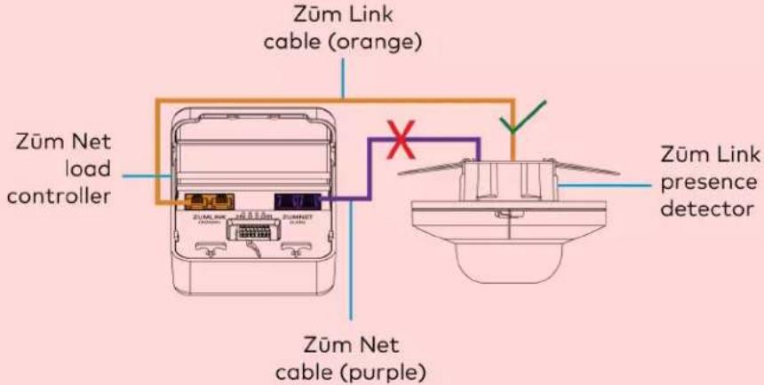
text_image
Zūm Link cable (orange) Zūm Net load controller Zūm Net cable (purple) Zūm Link presence detectorNOTES:
• Install and use this product in accordance with appropriate electrical codes and regulations.
- A licensed electrician should install this product.
In the Box
Qty. Description
1 Züm Wired Presence Detectors with Link Communication
Remove or Attach the Backplate
To remove the backplate from the presence detector:
-
Locate the two sliding tabs on opposite sides of the presence detector.
-
Extend the sliding tabs out of the housing. A flat-head screwdriver can be used. Once both sliding tabs are exposed, the presence detector releases from the backplate.
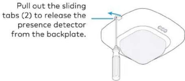
text_image
Pull out the sliding tabs (2) to release the presence detector from the backplate.To attach the backplate to the presence detector:
-
Ensure the sliding tabs are extended out of the housing.
-
Align the pins on the back of the presence detector with the socket on the backplate and press.

text_image
Match the pin set on the presence detector with the socket on the backplate. Presence detector (back view) Backplate (front view)- Push both sliding tabs back into the housing
Junction Box Mounting
The presence detectors are compatible with 4 in. square junction boxes, 4 in. round junction boxes, and 3 in. mud rings (not included). After the junction box is installed, follow the procedure for mounting the presence detectors.
-
Install the junction box according to its requirements.
-
Remove the backplate from the presence detector. Refer to Remove or Attach the Backplate on page 118.
-
Remove both spring tabs from the backplate. Use your fingers or needle-nose pliers.
a. Pinch one spring tab to minimize it's width.
b. Carefully lift the spring out of the housing.
c. Repeat the process with the other spring tab.
d. Discard the spring tabs.
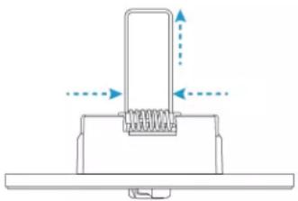
natural_image
Pure mechanical diagram showing a spring-loaded component with directional arrows, no text or symbols present- Feed the CBL-CAT5E-ZUMLINK-P cable through the junction box or mud ring, and connect it to the Züm Link Presence Detectors backplate.
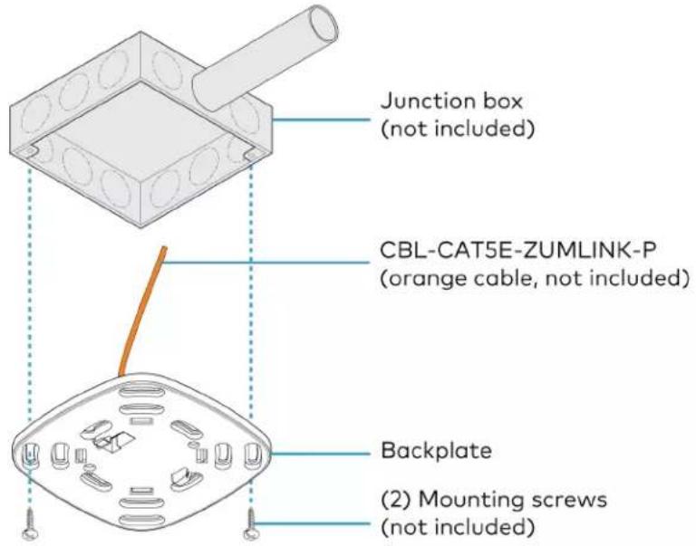
text_image
Junction box (not included) CBL-CAT5E-ZUMLINK-P (orange cable, not included) Backplate (2) Mounting screws (not included)For presence detectors with additional output relays, connect the relays to a relay-input capable device before mounting the backplate to the junction box or mud ring.

text_image
Junction box (not included) Relay wires: Green: Normally open Blue: Normally closed Red: Common CBL-CAT5E-ZUMLINK-P (orange cable, not included) Backplate (2) Mounting screws (not included)Relay connection applicable for the following presence detectors:
• ZUMLINK-IR-QUATTRO-DLS-RLY
• ZUMLINK-DT-QUATTRO-DLS-RLY
• ZUMLINK-US-QUATTRO-DLS-RLY
• ZUMLINK-IR-QUATTRO-HD-DLS-RLY
• ZUMLINK-US-HALLWAY-DLS-RLY
• ZUMLINK-US-ONEWAY-DLS-RLY
- Using two mounting screws (not included), attach the back plate to the electrical box or mud ring.
- Attach the presence detector to the backplate. Refer to Remove or Attach the Backplate on page 118.
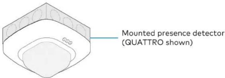
text_image
Mounted presence detector (QUATTRO shown)- Wire the presence detector according to the Züm Wired System Diagram on page 124
Ceiling Mounting
A mounting hole 2.69 in. (68 mm) to 3 in. (76 mm) in diameter must be cut before mounting the presence detector to the ceiling.
- Cut a mounting hole that is 2.69 in. (68 mm) to 3 in. (76 mm) in diameter.

text_image
Mounting hole diameter: 2.69 in. (68 mm) to 3 in. (76 mm)- Feed the CBL-CAT5E-ZUMLINK-P cable through the mounting hole, and connect it to the Züm Link Presence Detectors backplate.
For presence detectors with additional output relays, connect the relays to a relay-input capable device before mounting the backplate to the mounting hole.
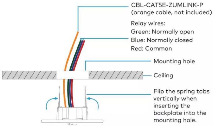
text_image
CBL-CAT5E-ZUMLINK-P (orange cable, not included) Relay wires: Green: Normally open Blue: Normally closed Red: Common Mounting hole Ceiling Flip the spring tabs vertically when inserting the backplate into the mounting hole.Relay connection applicable for the following presence detectors:
• ZUMLINK-IR-QUATTRO-DLS-RLY
• ZUMLINK-DT-QUATTRO-DLS-RLY
• ZUMLINK-US-QUATTRO-DLS-RLY
• ZUMLINK-IR-QUATTRO-HD-DLS-RLY
• ZUMLINK-US-HALLWAY-DLS-RLY
• ZUMLINK-US-ONEWAY-DLS-RLY
- Flip the backplate spring tabs to the vertical position and insert them into the mounting hole.

text_image
CBL-CAT5E-ZUMLINK-P (orange cable, not included) Mounting hole Ceiling Flip the spring tabs vertically when inserting the backplate into the mounting hole.When the spring tabs release, they snap back down to secure the backplate to the ceiling.

natural_image
Technical diagram of a mechanical or structural assembly with no visible text, numbers, or symbols.Release the spring tabs once they are in the mounting hole.
- Attach the presence detector to the backplate. Refer to Remove or Attach the Backplate on page 118.
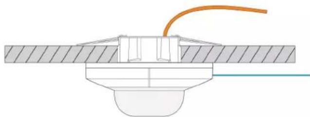
natural_image
Technical diagram of a mechanical assembly with no visible text or symbolsAttach the presence detector to the backplate. (QUATTRO shown)
- Wire the presence detector according to the Züm Wired System Diagram on page 124
Züm Wired System Diagram

flowchart
graph TD
    subgraph Room 1
        A["Züm Link Presence detector"] --> B["Züm Link power supply"]
        B --> C["Züm Link Presence detector"]
        D["Non-system sensor"] --> E["Züm Link load controller"]
        E --> F["Züm Link keypad"]
        G["Control system"] --> H["Network switch"]
        I["Room 2"] --> J["Züm Link universal dimmer"]
        J --> K["Züm Link Presence detector"]
        K --> L["Züm Link presence detector"]
        L --> M["Züm Link load controller"]
        M --> N["Züm Link keypad"]
        O["To next room (up to 20 devices)"] --> P["Züm Net (room-to-room control)"]
        Q["Züm Link (in-room control)"] --> R["Züm Link"]
        S["SW or LV control"] --> T["Züm Link"]
    end
    subgraph Room 2
        U["Züm Link universal dimmer"] --> V["Züm Link Presence detector"]
        V --> W["Züm Link presence detector"]
        X["Züm Link Universal dimmer"] --> Y["Züm Link Presence detector"]
        Y --> Z["Züm Link presence detector"]
        AA["Züm Link Universal dimmer"] --> AB["Züm Link Presence detector"]
        AB --> AC["Züm Link presence detector"]
        AD["Züm Link Universal dimmer"] --> AE["Züm Link Presence detector"]
        AE --> AF["Züm Link presence detector"]
        AG["Züm Link Universal dimmer"] --> AH["Züm Link Presence detector"]
        AH --> AI["Züm Link presence detector"]
        AJ["Züm Link Universal dimmer"] --> AK["Züm Link Presence detector"]
        AL["Züm Link Universal dimmer"] --> AM["Züm Link presence detector"]
        AN["Züm Link Universal dimmer"] --> AO["Züm Link presence detector"]
        AP["Züm Link Universal dimmer"] --> AQ["Züm Link presence detector"]
        AR["Züm Link Universal dimmer"] --> AS["Züm Link presence detector"]
        AT["Control system"] --> AU["Network switch"]
    end
NOTES:
- Daisy-chain up to 20 Züm Net devices (up to 328 ft (100 m) between Züm Net devices) with purple CBL-CAT5E-ZUMNET-P RJ-45 cables (sold separately).
- Do not exceed three network switches between a ZUM-HUB4 and a Zūm Net device.
- System sensors communicate digitally via Zūm Link. Non-system sensors communicate via an analog connection on a Zūm Wired load controller.
For more information, refer to the following topics:
• Presence Detectors Operation on page 156
• Züm App Configuration on page 158
Beam Pattern Coverage
NOTE: Detection along the far edge of the detection range may be inconsistent.
ZUMLINK-IR-QUATTRO-HD-DLS/ ZUMLINK-IR-QUATTRO-HD-DLS-RLY
Top View
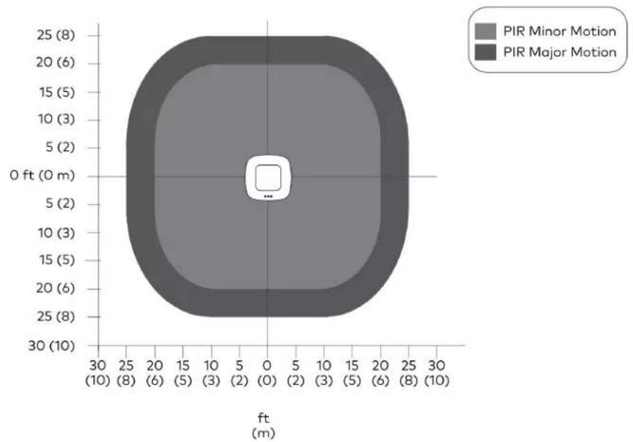
radar
| PIR Motion Level | Altitude (ft) | Count | | ----------------- | ------------- | ----- | | Minor Motion | 0 | 1 | | Major Motion | 0 | 1 |Side View

area
| ft (m) | PIR Minor Motion (ft) | PIR Major Motion (ft) | | ------ | --------------------- | --------------------- | | 0 | 0 | 0 | | 5 | ~1.5 | ~1.2 | | 10 | ~3.0 | ~2.5 | | 15 | ~4.5 | ~3.8 | | 20 | ~6.0 | ~5.0 | | 25 | ~7.5 | ~6.2 | | 30 | ~9.0 | ~7.5 |ZUMLINK-DT-QUATTRO-DLS/ ZUMLINK-DT-QUATTRO-DLS-RLY
Top View
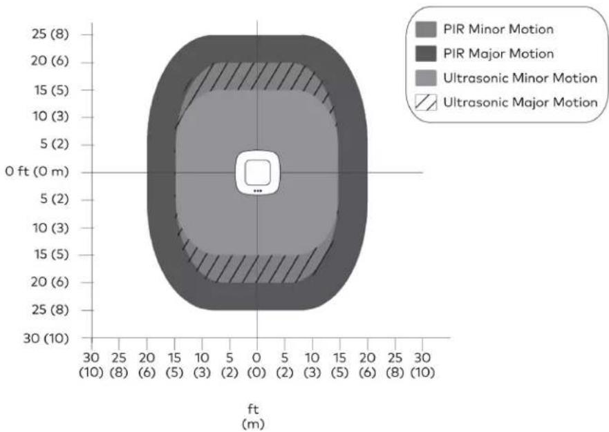
radar
| Motion Type | Value | | ----------------------- | ----- | | PIR Minor | 8 | | PIR Major | 6 | | Ultrasonic Minor | 5 | | Ultrasonic Major | 2 |Side View Sensor Orientation A
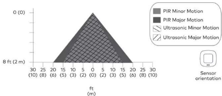
area
| Sensor orientation | Position (ft) | Height (ft) | | ------------------ | ------------- | ----------- | | PIR Minor Motion | 0 | 0 | | PIR Major Motion | 0 | 0 | | Ultrasonic Minor Motion | 0 | 0 | | Ultrasonic Major Motion | 0 | 0 |Side View Sensor Orientation B
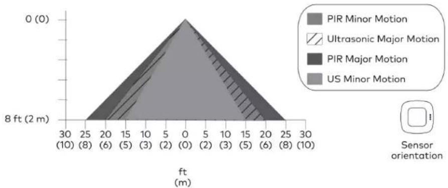
area
| Motion Type | Position (m) | Height (ft) | | ------------------- | ------------ | ----------- | | PIR Minor Motion | 30 | 0 | | PIR Minor Motion | 25 | 0 | | PIR Minor Motion | 20 | 0 | | PIR Minor Motion | 15 | 0 | | PIR Minor Motion | 10 | 0 | | PIR Minor Motion | 5 | 0 | | PIR Minor Motion | 0 | 0 | | PIR Minor Motion | 5 | 0 | | PIR Minor Motion | 10 | 0 | | PIR Minor Motion | 15 | 0 | | PIR Minor Motion | 20 | 0 | | PIR Minor Motion | 25 | 0 | | PIR Minor Motion | 30 | 0 | | Ultrasonic Major Motion | 30 | 0 | | Ultrasonic Major Motion | 25 | 0 | | Ultrasonic Major Motion | 20 | 0 | | Ultrasonic Major Motion | 15 | 0 | | Ultrasonic Major Motion | 10 | 0 | | Ultrasonic Major Motion | 5 | 0 | | Ultrasonic Major Motion | 0 | 0 | | Ultrasonic Major Motion | 5 | 0 | | Ultrasonic Major Motion | 10 | 0 | | Ultrasonic Major Motion | 15 | 0 | | Ultrasonic Major Motion | 20 | 0 | | Ultrasonic Major Motion | 25 | 0 | | Ultrasonic Major Motion | 30 | 0 | | PIR Major Motion | 30 | 0 | | PIR Major Motion | 25 | 0 | | PIR Major Motion | 20 | 0 | | PIR Major Motion | 15 | 0 | | PIR Major Motion | 10 | 0 | | PIR Major Motion | 5 | 0 | | PIR Major Motion | 0 | 0 | | PIR Major Motion | 5 | 0 | | PIR Major Motion | 10 | 0 | | PIR Major Motion | 15 | 0 | | PIR Major Motion | 20 | 0 | | PIR Major Motion | 25 | 0 | | PIR Major Motion | 30 | 0 | | US Minor Motion | 30 | 0 | | US Minor Motion | 25 | 0 | | US Minor Motion | 20 | 0 | | US Minor Motion | 15 | 0 | | US Minor Motion | 10 | 0 | | US Minor Motion | 5 | 0 | | US Minor Motion | 0 | 0 | | US Minor Motion | 5 | 0 | | US Minor Motion | 10 | 0 | | US Minor Motion | 15 | 0 | | US Minor Motion | 20 | 0 | | US Minor Motion | 25 | 0 | | US Minor Motion | 30 | 0 |ZUMLINK-US-HALLWAY-DLS/ ZUMLINK-US-HALLWAY-DLS-RLY
Top View
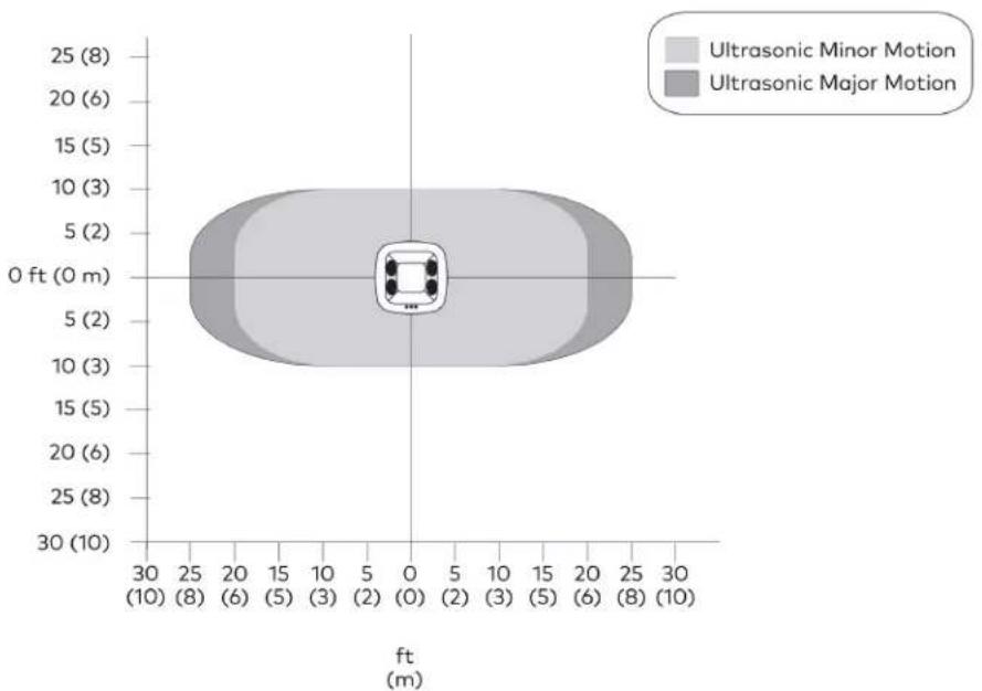
violin
| Motion Type | Value | | ----------------------- | ----- | | Ultrasonic Minor Motion | 2 | | Ultrasonic Major Motion | 2 |Side View Sensor Orientation A
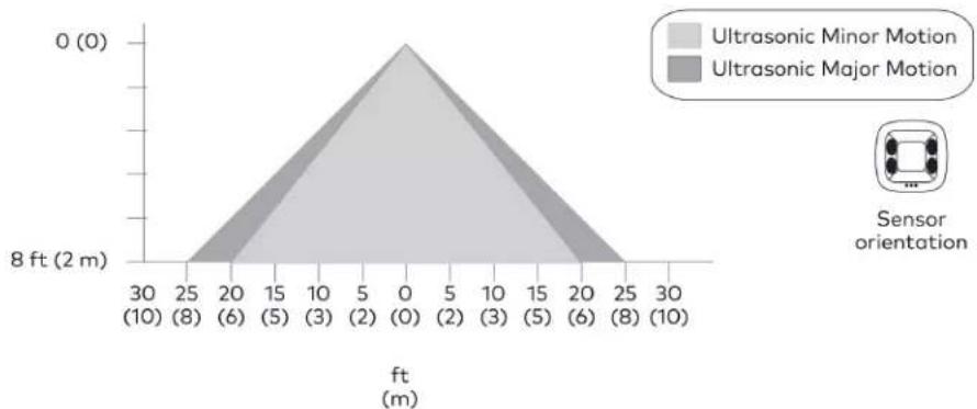
area
| ft (m) | Ultrasonic Minor Motion (ft) | Ultrasonic Major Motion (ft) | | ------ | --------------------------- | --------------------------- | | 0 | 0 | 0 | | 5 | 0 | 0 | | 10 | 0 | 0 | | 15 | 0 | 0 | | 20 | 0 | 0 | | 25 | 0 | 0 | | 30 | 0 | 0 |Side View Sensor Orientation B

area
| Position (ft) | Distance (m) | | ------------- | ------------ | | 0 | 0 | | 5 | 0 | | 10 | 0 |Mount the ZUM-HUB4 and connect it to the network. The ZUM-HUB4 can be mounted into a rack or placed onto a flat surface.
In the Box
Qty. Description
| 1 ZUM-HUB4, 4-SeriesTM Control Processor for Zūm® Lighting Control System |
| Additional Items |
| 1 Connector, 4-Pin (2003576) |
| 1 Power Pack, 24VDC, 2.5A, 100-240VAC (2045873) |
| 2 Bracket, Rack Ear, 1U (2032122) |
| 4 Foot, 0.5 in. x 0.5 in. x 0.23 in., Rubber, Black (2002389) |
| 1 Power Cord, 5 ft 10 in. (1.78 m) (2042043) |
Mount to a Rack
The hub occupies 1U of rack space.
To install the included rack ears:
- Use a #1 or #2 Phillips screwdriver to remove the three screws from each side of the front of the device as shown in the following illustration.
-
Use the screwdriver and the screws removed in the previous step to attach the included rack ears to the device.
-
Mount the device into the rack using four mounting screws (not included).
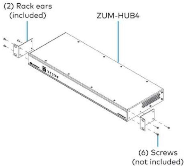
text_image
(2) Rack ears (included) ZUM-HUB4 (6) Screws (not included)Place onto a Flat Surface
When placing the device onto a flat surface or stacking it with other equipment, attach the included rubber feet near the corners on the underside of the device.
Make Connections
The hub has a dedicated Control Subnet that is used for communication between the control system and Crestron Ethernet devices. This subnet allows for dedicated communication between the control system and Crestron Ethernet devices without interferences from other network traffic on the LAN.
Make the connections, and note the following:
- Use Crestron power supplies for Crestron equipment.
• The included cable(s) cannot be extended. - Apply power after all connections have been made.
NOTES:
- Ensure the unit is properly grounded by connecting the chassis ground lug to an earth ground (building steel).
• The hub can be powered with the (included) 24VDC power pack. - Do not connect the CONTROL SUBNET port to the LAN. The CONTROL SUBNET port must be connected only to Crestron Ethernet devices.
Connections
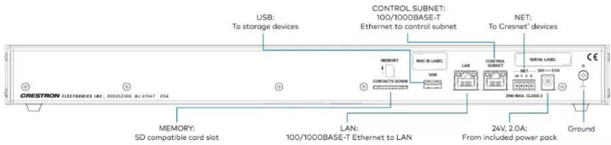
text_image
CRESTRON ELECTRONICS INC., ROCELEIGH, NJ 67047 USA USB: To storage devices CONTROL SUBNET: 100/1000BASE-T Ethernet to control subnet NET: To Cresnet* devices MEMORY MAC ID LABEL MEMORY CONTACTS DOWN LAN CONTROL SUBNET SERIAL LABEL NET 24V 2.0A 24V MAX. CLASS.2 24V, 2.0A: From included power pack MEMORY: SD compatible card slot LAN: 100/1000BASE-T Ethernet to LAN GroundZūm Wired System Diagram

flowchart
graph TD
    subgraph Room 1
        A["Züm Link Presence detector"] --> B["Züm Link power supply"]
        B --> C["Züm Link Presence detector"]
        C --> D["Non-system sensor"]
        D --> E["Züm Link load controller"]
        E --> F["Züm Link keypad"]
        G["Control system"] --> H["Network switch"]
        I["Room 2"] --> J["Züm Link universal dimmer"]
        J --> K["Züm Link Presence detector"]
        K --> L["Züm Link presence detector"]
        L --> M["Züm Link load controller"]
        M --> N["Züm Link keypad"]
        O["To next room (up to 20 devices)"] --> P["Züm Net (room-to-room control)"]
        Q["To next room (up to 20 devices)"] --> R["Züm Link (in-room control)"]
        S["To next room (up to 20 devices)"] --> T["Züm Link keypad"]
    end

    subgraph Room 2
        U["Züm Link universal dimmer"] --> V["Züm Link Presence detector"]
        V --> W["Züm Link presence detector"]
        W --> X["Züm Link load controller"]
        X --> Y["Züm Link keypad"]
        Z["To next room (up to 20 devices)"] --> AA["Züm Net (room-to-room control)"]
        AB["To next room (up to 20 devices)"] --> AC["Züm Link (in-room control)"]
        AD["To next room (up to 20 devices)"] --> AE["Züm Link keypad"]
    end

    subgraph Room 3
        AF["Züm Link power supply"] --> AG["Züm Link Presence detector"]
        AG --> AH["Züm Link load controller"]
        AH --> AI["Züm Link keypad"]
        AJ["Non-system sensor"] --> AK["Züm Link load controller"]
        AL["Control system"] --> AM["Network switch"]
    end

    subgraph Room 4
        AN["Züm Link universal dimmer"] --> AO["Züm Link Presence detector"]
        AO --> AP["Züm Link presence detector"]
        AP --> AQ["Züm Link load controller"]
        AQ --> AR["Züm Link keypad"]
        AS["To next room (up to 20 devices)"] --> AT["Züm Net (room-to-room control)"]
        AU["To next room (up to 20 devices)"] --> AV["Züm Link (in-room control)"]
        AW["To next room (up to 20 devices)"] --> AX["Züm Link keypad"]
NOTES:
- Daisy-chain up to 20 Züm Net devices (up to 328 ft (100 m) between Züm Net devices) with purple CBL-CAT5E-ZUMNET-P RJ-45 cables (sold separately).
- Do not exceed three network switches between a ZUM-HUB4 and a Zūm Net device.
- System sensors communicate digitally via Zūm Link. Non-system sensors communicate via an analog connection on a Zūm Wired load controller.
To configure the hub, refer to Hub Web Interface on page 229 for details.
Cable Accessory Installation
Refer to the following sections for using the ZUMLINK-SPLTR-RJ45 and ZUMLINK-CONV-CN in a Züm Wired system.
In the Box
Qty. Description
1 ZUMLINK-CONV-CN, Züm® Wired Adapter Cable for Cresnet® Devices or ZUMLINK-SPLTR-RJ45, Züm® Wired RJ-45 Splitter
ZUMLINK-SPLTR-RJ45 Connections
The ZUMLINK-SPLTR-RJ45 is a pass-through accessory that splits one Zūm link signal into two ports. Use Zūm link cable (CBL-CAT5E-ZUMLINK-P) to connect bidirectional RJ-45 ports to Zūm link devices, including Zūm link load controllers, sensors, or keypads.
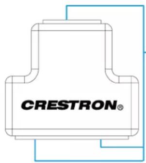
text_image
CRESTRON®(3) ZUM LINK
RJ-45 ports:
To Zūm link devices
via Zūm link cable
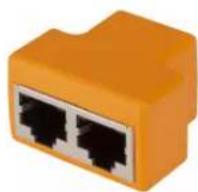
ZUMLINK-CONV-CN Connections
The ZUMLINK-CONV-CN integrates Cresnet devices into a Zūm system. Use the Zūm link cable (CBL-CAT5E-ZUMLINK-P) to connect the RJ-45 port to Zūm link sensors and keypad. Connect the Cresnet terminal block to legacy Cresnet lighting products, including a SpaceBuilder® system (such as the CL-SPACEBUILDER-DIN) or traditional processor panel.
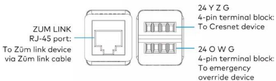
text_image
ZUM LINK RJ-45 port: To Züm link device via Züm link cable 24 Y Z G 4-pin terminal block: To Cresnet device 24 O W G 4-pin terminal block: To emergency override deviceCresnet Terminal Block Connections
| Terminal Description |
| 24 24V power |
| Y Data terminal pass-through only |
| Z Data terminal pass-through only |
| G Ground |
Emergency Override Terminal Block Connections
| Terminal Description |
| 24 24V power |
| O Emergency override |
| W Future use |
| G Ground |
Applications
The following diagram is a sample application.
Integrating a Legacy Lighting System into a Züm System
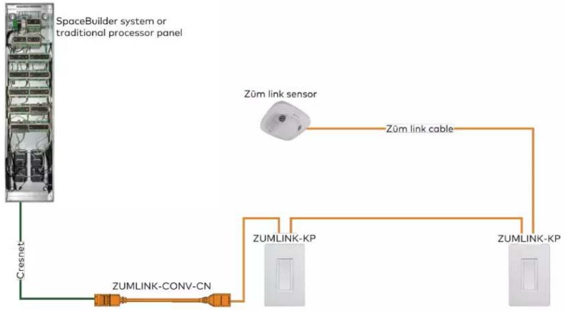
flowchart
graph TD
    A["SpaceBuilder system or traditional processor panel"] --> B["Cresnet"]
    B --> C["ZUMLINK-CONV-CN"]
    C --> D["ZUMLINK-KP"]
    D --> E["ZUMLINK-KP"]
    F["Zum link sensor"] --> G["Zum link cable"]
    G --> D
Using a Züm Link Splitter (ZUMLINK-SPLTR-RJ45)
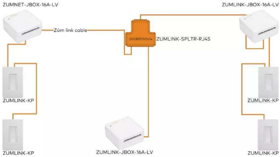
flowchart
graph TD
    A["ZUMNET-JBOX-16A-LV"] -->|Zūm link cable| B["ZUMLINK-SPLTR-RJ45"]
    C["ZUMLINK-KP"] --> B
    D["ZUMLINK-KP"] --> B
    E["ZUMLINK-JBOX-16A-LV"] --> B
    F["ZUMLINK-KP"] --> B
    G["ZUMLINK-JBOX-16A-LV"] --> B
    H["ZUMLINK-KP"] --> B
    I["ZUMLINK-JBOX-16A-LV"] --> B
Power Supply Installation
The ZUMLINK-JBOX-PSU mounts directly to a 4 in. square junction box (sold separately) and connects to other Zūm Link devices via CBL-CAT5E-ZUMLINK-P cables (sold separately).
In the Box
Qty. Description
1 ZUMLINK-JBOX-PSU, Zūm® Wired J-Box Power Supply
Additional Items
5 Yellow Wire Nut, 22-10 AWG (2049245)
1 Locknut (2047626)
1 Tie Wrap (2005429)
Install the Power Supply
WARNINGS:
- To avoid fire, shock, or death, turn off the power at the circuit breaker or fuse and test that the power is off before wiring!
- Do NOT connect standard Ethernet ports on network-based devices to the orange Zūm Link ports on any Zūm Link or Zūm Net device. Also, do NOT connect the purple Zūm Net ports on the Zūm Net device to the orange Zūm Link ports on any Zūm Link device. These connections may damage network devices.

text_image
Zūm Link cable (orange) Zūm Net load controller Zūm Net cable (purple) Zūm Link power supplyNOTES:
• Install and use this product in accordance with appropriate electrical codes and regulations.
• A licensed electrician should install this product.
- The product should project from the junction box when installed.
- For use where temperatures are between 32^ to 104^ ( 0^ to 40^ )
- For Chicago plenum compliant installations:
- Ensure that the junction boxes and other electrical components are rated for Chicago plenum.
Separate the high-voltage lines from the low-voltage cables. - Install two junction boxes: one junction box for the high-voltage lines and one junction box for the low-voltage cables and load controller. A 6 in. square, 3.5 in. deep box with conduit knockouts is recommended for the low-voltage cables and load controller.
To install a power supply:
- Turn the power off at the circuit breaker.
- Mount the power supply to the junction box using the included locknut.

text_image
Locknut Junction box- Wire the power supply as shown in the following diagrams.
ZUMLINK-JBOX-PSU Wiring to Other Züm Link Devices

text_image
ZUMLINK (4): (orange) To Zūm Link devices ZUMLINK (ROOM) ZUMLINK (ROOM)ZUMLINK-JBOX-PSU Wiring

text_image
100-277VAC power from breaker Neutral (=white) Hot (—black) To Zūm Link devices (orange)ZUMLINK-JBOX-PSU Wiring to Meet Chicago Electric Code

text_image
100-277VAC power from breaker Neutral (=white) Hot (—black) 6 in. square, 3.5 in. deep box with conduit knockouts recommended To Züm Link devices (orange)Züm Wired System Diagram

flowchart
graph TD
    subgraph Room 1
        A["Züm Link Presence detector"] --> B["Züm Link power supply"]
        B --> C["Züm Link Presence detector"]
        C --> D["Non-system sensor"]
        D --> E["Züm Link load controller"]
        E --> F["Züm Link keypad"]
        G["Control system"] --> H["Network switch"]
        I["Room 2"] --> J["Züm Link universal dimmer"]
        J --> K["Züm Link Presence detector"]
        K --> L["Züm Link presence detector"]
        L --> M["Züm Link load controller"]
        M --> N["Züm Link keypad"]
        O["To next room (up to 20 devices)"] --> P["Züm Net (room-to-room control)"]
        Q["Züm Link (in-room control)"] --> R["Züm Link"]
        S["SW or LV control"] --> T["Züm Link"]
    end
    subgraph Room 2
        U["Züm Link universal dimmer"] --> V["Züm Link Presence detector"]
        V --> W["Züm Link presence detector"]
        W --> X["Züm Link load controller"]
        X --> Y["Züm Link keypad"]
        Z["To next room (up to 20 devices)"] --> AA["Züm Net (room-to-room control)"]
        AB["24VDC control"] --> AC["Züm Link (in-room control)"]
        AD["SW or LV control"] --> AE["Züm Link"]
NOTES:
- Daisy-chain up to 20 Züm Net devices (up to 328 ft (100 m) between Züm Net devices) with purple CBL-CAT5E-ZUMNET-P RJ-45 cables (sold separately).
- Do not exceed three network switches between a ZUM-HUB4 and a Zūm Net device.
- System sensors communicate digitally via Zūm Link. Non-system sensors communicate via an analog connection on a Zūm Wired load controller.
Rocker and Button Tree Installation
The ZUMLINK-KP comes preassembled with the white ZUMLINK-BTNR rocker button. The following procedure describes how to replace the bezel and rocker button with a new bezel and rocker button/button tree.
In the Box
Qty. Description
1 ZUMLINK-BTN, 2, 4, 6, or 8 Button Tree with Bezel for Züm® Light Control Keypads (ZUMLINK-KP) or
ZUMLINK-BTNR, Rocker Button with Bezel for Zūm® Light Control Keypads (ZUMLINK-KP)
NOTE: ZUMLINK-BTN and ZUMLINK-BTNR are available with blank, pad-printed, or custom engraved buttons and in almond, black, gray, red, and white finishes.
Install a Bezel and Rocker Button or Button Tree
To replace the bezel and rocker button with a new bezel and rocker button/button tree:
- Remove the faceplate from the keypad.
If a Crestron FP-G series faceplate (not included) is installed, remove only the cover.
- Use a flat-head screwdriver to remove the bezel and rocker button by pressing the screwdriver into the notches on the side of the keypad.
The bezel and rocker button release from the keypad.

text_image
Apply pressure with a flat-head screwdriver to the notches, and release the bezel and rocker button. Backplate for an FP-G series faceplate (not included)-
Position the replacement rocker button/button tree on the keypad.
-
Place the replacement bezel on top of the rocker button/button tree, making sure to align the LED hole with the LED on the keypad, and snap the bezel into place.
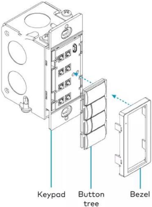
text_image
Keypad Button tree BezelFor more information about installing the ZUMLINK-KP, refer to Keypad Installation on page 109.
Operation
A Zūm Wired space consists of at least one Zūm Net or Zūm Link load controller connected to lights, sensors or another Zūm Wired device. Once the devices are installed and connected together in a space, they communicate with each other. Without any programming, the devices behave as described below.
NOTE: To add an Züm Wired device to an existing space, simply connect the device and it will become part of the space logic.
Refer to the following operation sections.
- Load Controller Operation
• Universal Dimmer Load Controller Operation - Keypad Operation
• Presence Detectors Operation
Load Controller Operation
In a room with multiple load controllers, one load controller is the primary controller and the others are secondary. Observe the LINK LED to identify the primary load controller. The LINK LED on the primary load controller consistently flashes for 0.5 seconds on and 0.5 seconds off.
Additional LED behavior is described in the following tables.
LED Status for Room Primary Load Controllers
| LED LED Color Description | |
| LINK Off The load controller is not polling any secondary load controllers. | |
| LINK Green (flashes 0.5 seconds on and 0.5 seconds off) | The load controller is the room primary load controller. |
| TEST Off The local load is off. | |
| TEST Green The local load is on. | |
| NET (ZUMNET-JBOX only) | Off The ZUMNET-JBOX is not connected to a control system or ZUM-HUB4. |
| NET (ZUMNET-JBOX only) | Green The ZUMNET-JBOX is connected to a control system or ZUM-HUB4. |
| NET (ZUMNET-JBOX only) | Red The ZUMNET-JBOX lost connection to a control system or ZUM-HUB4. |
LED Status for Secondary Load Controllers (ZUMLINK-JBOX only)
| LED LED Color Description | ||
| LINK Off | The load controller is not being polled by the room primary load controller. | |
| LINK Green (solid) | The load controller is actively being polled by the room primary load controller. | |
| TEST Off | The local load is off. | |
| TEST Green | The local load is on. | |
Perform a Factory Reset on a Load Controller
On the load controller, press and hold the TEST button for 10 seconds. Release the button when all LEDs turn red. Wait a few seconds for the factory reset to finish.
NOTES:
- Performing a factory reset on the primary Züm Wired load controller restores the space to default functionality and resets the load controller as a secondary device that no longer controls the space. Refer to Assign a Load Controller as the Primary Controller on page 150.
- Performing a factory reset on any other Zūm Wired load controller or device in the space only restores the default settings for that device.
Assign a Load Controller as the Primary Controller
Change a load controller from the primary controller to secondary or a secondary controller to primary.
NOTES:
- Only one load controller can be assigned as the primary load controller in a Zūm space.
- Zūm Net load controllers are preconfigured as a primary devices. In applications with more than one Zūm Net load controller in the same Zūm space, keep one Zūm Net load controller as the primary controller and follow the procedure to set the others as secondary controllers.
To assign aload controller as the primary or secondary controller:
- Tap the TEST button three times, then press and hold for five to seven seconds.
- Release the button when the LINK LED flashes red. The load controller reboots.
After three to five minutes, the LINK LED flashes 0.5 seconds on and 0.5 seconds off consistently.
- Connect to the Züm app and confirm the load controller assignment.
Reboot a Load Controller
To reboot a load controller:
- Tap the TEST button four times, then press and hold for five seconds.
- Release the button when all LEDs flash red.
Remove a Missing Device from a Zūm Wired Room
To remove a missing device from a Zūm Wired room:
- Identify the primary load controller.
The LINK LED on the primary load controller consistently flashes for 0.5 seconds on and 0.5 seconds off.
- Perform a factory reset on the load controller.
Refer to Perform a Factory Reset on a Load Controller on page 149. Refer to Perform a Factory Reset on a Load Controller.
- Reassign the load controller as the primary controller.
Refer to Assign a Load Controller as the Primary Controller on page 150.
NOTE: Performing a factory reset on a primary load controller erases all previous room logic to the default settings.
Refer to Zūm App Configuration on page 158 for configuring the device.
Universal Dimmer Load Controller Operation
Follow the sections below to operate the ZUMLINK-EXP-16A-DIMU and configure the device. To configure the device using the Züm app, refer to Universal Dimmer Load Controller Züm App Configuration on page 198.
Set the Dimming Mode
The ZUMLINK-EXP-16A-DIMU uses Auto Dimming mode to determine the attached load type and applies Forward Phase (leading edge) or Reverse Phase (trailing edge) Dimming mode based on the auto-detected load type.
WARNINGS:
- Auto Dimming mode should not be disabled unless suggested by a Crestron True Blue Technical Support representative. Incorrectly setting these switches to force the wrong mode can cause damage to the dimmer and lighting fixture or create a hazardous condition.
- Only use Center Dimming mode if instructed by a Crestron True Blue Technical Support representative.
If necessary, set the ZUMLINK-EXP-16A-DIMU to operate in Forward Phase, Reverse Phase, or Center Phase Dimming mode.
- Remove the cover as shown in Universal Dimmer Load Controller Operation on page 152.
- Press the DIM MODE button until the desired dimming mode is indicated by the REV, AUTO, FWD, or CENTER LED.
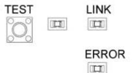
text_image
TEST LINK ERROR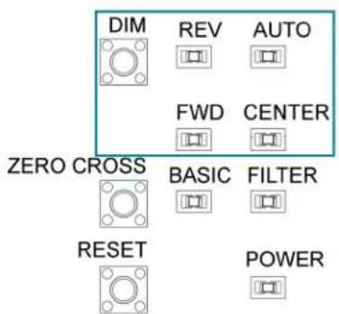
text_image
DIM REV AUTO FWD CENTER ZERO CROSS BASIC FILTER RESET POWERTest the Loads
To verify system wiring, the loads can be tested before setting up the Züm space. Press the TEST button to toggle the connected loads on and off. Press and hold the TEST button to cycle dim the connected loads.
Factory Reset
A factory reset should be performed when the ZUMLINK-EXP-16A-DIMU is removed from the network or to remove the configuration settings from the device. The ZUMLINK-EXP-16A-DIMU must also be factory reset if it is being moved to a different system.
NOTE: New-in-box devices do not need to be factory reset before joining a system.
To factory reset the ZUMLINK-EXP-16A-DIMU, press and hold the TEST button until the TEST LED lights (about 10 seconds), and then release the button. The TEST LED and the connected load output turn on to indicate that the factory reset procedure is complete.
Universal Dimmer LEDs
The LEDs on the cover operate as follows:
- TEST: Lights when the connected loads are on.
- NET: Lights to indicate that it is joined to a Zūm space. Flashes when the ZUMLINK-EXP-16A-DIMU receives a message.
- ERROR: Flashes to indicate an error in the line or load. Refer to Error States on page 154.
- AUTO: Lights to indicate that the dimmer is in Auto Dimming mode. When operating in Auto Dimming mode, the REV or FWD LED lights to indicate the dimming mode is in use.
- REV: Lights to indicate that the dimmer is in Reverse Phase Dimming mode.
- FWD: Lights to indicate that the dimmer is in Forward Phase Dimming mode.
- CENTER: Lights to indicate that the dimmer is in Center Phase Dimming mode.
- FILTER: Lights to indicate that the zero-cross filter is applying filtering to sync the AC line power.
- BASIC: Lights to indicate that the zero-cross filter is performing basic filtering.
Error States
The following table provides corrective action error states that are indicated by the ERROR LED. If further assistance is required, please contact a Crestron True Blue Technical Support representative.
| LED Flash Pattern | Issue Action | |
| 1-1 The secondary processor is in bootloader. | Power cycle the unit. | |
| 1-2 The secondary processor is unresponsive. | Power cycle the unit. | |
| 1-3 The secondary processor firmware update failed. | Power cycle the unit. | |
| 2-1 There is an overcurrent error. | Check the output for a short circuit or overload. Verify that the device is not dimming in Forward Phase Dimming mode with incandescent or electronic drivers connected. | |
| 2-2 A FET is shorted. Contact Crestron's True Blue Technical Support. | ||
| 2-3 An overtemperature error exists. | Check the output for overload. Ensure that the device is receiving adequate air for cooling. | |
| 2-4 An overvoltage error exists. | Verify that the device is not dimming magnetic transformer loads in Reverse Phase Dimming mode. | |
| 3-1 A zero-cross sync error exists. | Change the Zero-cross mode from Basic mode to Filter mode. | |
| 3-2 No AC Power. Verify that the incoming AC voltage is within spec. | ||
Zero-Cross Filter
An unusual line condition, indicated by a 3-1 flash pattern from the ERROR LED, can be corrected by changing the Zero-cross mode from Basic mode (default) to Filter mode. Consult with Crestron's True Blue Technical Support before changing the Zero-cross mode. To change the Zero-cross mode:
- Remove the cover as shown in Universal Dimmer Load Controller Operation on page 152.
-
Press the ZERO CROSS button. The BASIC or FILTER LED lights.
-
BASIC LED: Indicates that basic filtering is being performed.
- FILTER LED: Indicates that the ZUMLINK-EXP-16A-DIMU is using filters to sync the AC line power.
Keypad Operation
The ZUMLINK-KP-R controls most of the connected load controllers in a space.
NOTE: The ZUMLINK-KP-R will not control a ZUMLINK-JBOX-20A-PLUG.
ZUMLINK-KP Functionality When Connected to Load Controllers
| Load Controller | Top Button Tap | Top Button Hold | Bottom Button Tap | Bottom Button Hold |
| ZUMNET-JBOX-16A-LV and ZUMLINK-JBOX-16A-LV | Recalls Scene 1 | Raise all loads | Recalls Off | Lower all loads |
| ZUMLINK-JBOX-20A-SW Recalls On N/A | Recalls Off N/A | |||
| ZUMLINK-JBOX-20A-PLUG N/A | N/A N/A N/A |

text_image
Top button Bottom buttonThe ZUMLINK-KP-R can be used with any ZUMLINK-BTN button tree for up to 8 programmable buttons. Use the Züm app to change a button's default functionality. Each of the buttons can be programmed with the following functions:
- None
- Off: Assigned loads controllers turn off.
- On: Assigned loads turn on
- Raise: Assigned load controllers raise.
- Lower: Assigned load controllers lower.
- Recall Scene 1 - Scene 16: Assigned load controllers recall the behavior set for the specified scene.
Refer to Züm App Configuration on page 158 for configuring the device.
Presence Detectors Operation
Non-system (such as the GLA-IR-QUATTRO-HD-COM1-24 or GLS-ODT-C-NS) and system sensors (such as the ZUMLINK-IR-QUATTRO-DLS) will trigger and control the connected load controller. Non-system sensors connect to the load controller via the I/O ports, while system sensors connect to the load controller via a CBL-CAT5E-ZUMLINK-P cable.
For presence detectors with a relay (such as the ZUMLINK-IR-QUATTRO-DLS-RLY), the default function is set to None. Use the Zūm app to change the functionality to follow occupancy logic or button presses.
Presence Detector Functionality When Connected to Load Controllers
| Load Controller Occupancy Detected Vacancy Detected | ||
| ZUMNET-JBOX-16A-LV and ZUMLINK-JBOX-16A-LV | Recalls Scene 1 (all on) | Recalls Scene 16 (all off) |
| ZUMLINK-JBOX-20A-SW On Recalls Scene 16 (all off) | ||
| ZUMLINK-JBOX-20A-PLUG On Off after grace period | delay | |
Refer to Züm App Configuration on page 158 for configuring the device.
To adjust the presence detector sensitivity, refer to Sensor Test Mode on page 223.
Configuration
Before using a Zūm Wired device, ensure it is updated with the latest firmware. Check for the latest firmware at www.crestron.com/firmware. Load the firmware onto the device using Crestron Toolbox™ software, the ZUM-HUB4 web interface (refer to Version Management on page 265), or the Zūm app (refer to Update Firmware with the Zūm App on page 164).
Once all of the devices are installed in the space and using the latest firmware, use the Zūm app to modify default room behavior. Expedite commissioning by copying a room configuration and sending it to a room with identical devices. Save a room configuration template and share it via email, or other methods available on the device. A template can be deployed to any identical room via the Zūm app or the ZUM-HUB4.
NOTE: The ZUMLINK-KP Bluetooth® connection is required to configure a Zūm wired space with the Zūm app.
This section provides the following information:
• Zūm App Configuration
- Hub Web Interface
Zūm App Configuration
Download the Zūm app from the Google Play™ online store or the Apple® App Store® online store.
To use the Zūm app:
- Enable Bluetooth wireless connection on your device to communicate with the Züm space.
- Launch the Zūm app and grant the permissions the app requests. The Zūm app displays a list of available spaces.

text_image
Nearby Rooms Swipe down to refresh. Swipe right from the left screen edge to show the Help menu. Tap on any of the rooms below to pair with it. 2131NEJ06972-ZUMNET-JBOX-1... Signal Strength - 60 2121NEJ11176-ZUMNET-JBOX-D... Signal Strength - 66 Room Firmware New release is available Download Firmware v1.03.42-
If new firmware is detected, update the firmware. Refer to Update Firmware with the Zūm App on page 164.
-
Select the desired space.
-
When prompted, enter the PIN. The Zūm app main screen opens.
NOTES:
- For Primary load controllers running firmware 3.6.18 and higher, the default PIN is 246800. For firmware lower than 3.6.18, the default PIN is 2468.
- To change the PIN, navigate to the Room Settings. When changing the PIN, the previous PIN is required.
- The first failed log-in attempt locks the user out of the Zūm space. With subsequent failed attempts, the lockout duration increases up to 60 minutes.
- The lockout duration resets when the correct PIN is entered, the Primary load controller reboots, or when the PIN is changed from the Web-Interface.
Zūm App Main Screen
From the Nearby Rooms screen, tap the desired room to open the Main screen. The following sections describe the actions available for each area of the Main screen.
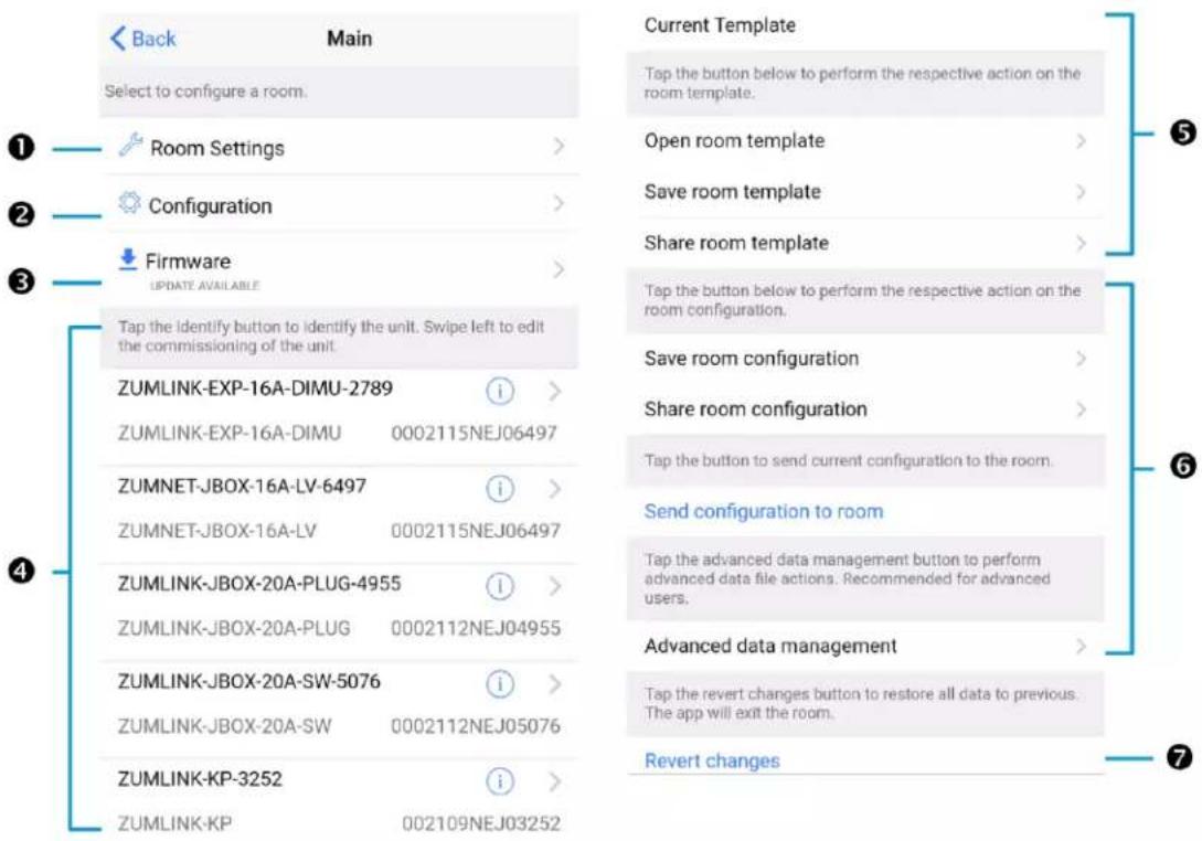
text_image
Back Main Select to configure a room. Room Settings > Configuration > Firmware UPDATE AVAILABLE > Tap the identify button to identify the unit. Swipe left to edit the commissioning of the unit. ZUMLINK-EXP-16A-DIMU-2789 ZUMLINK-EXP-16A-DIMU 0002115NEJ06497 ZUMNET-JBOX-16A-LV-6497 ZUMNET-JBOX-16A-LV 0002115NEJ06497 ZUMLINK-JBOX-20A-PLUG-4955 ZUMLINK-JBOX-20A-PLUG 0002112NEJ04955 ZUMLINK-JBOX-20A-SW-5076 ZUMLINK-JBOX-20A-SW 0002112NEJ05076 ZUMLINK-KP-3252 ZUMLINK-KP 002109NEJ03252 Current Template Tap the button below to perform the respective action on the room template. Open room template > Save room template > Share room template > Tap the button below to perform the respective action on the room configuration. Save room configuration > Share room configuration > Tap the button to send current configuration to the room. Send configuration to room Tap the advanced data management button to perform advanced data file actions. Recommended for advanced users. Advanced data management > Tap the revert changes button to restore all data to previous. The app will exit the room. Revert changes ① ② ③ ④ ⑤ ⑥ ⑦NOTE: The numbers below correspond with the numbers in the Main screen diagram.
-
Room Settings: Edit the Room Name, PIN, Floor ID, Zone ID, and Network information.
-
Configuration: Edit the room logic to view the current state of the room.
-
Occupancy Sensors: View details for the connected sensor(s) or edit the sensor name.
- Photo Sensors: View details for the connected sensor(s) or edit the sensor name.
- Load Controllers: Identify and view details for the connected load controller(s).
- ZUMLINK-JBOX-16A-LV and ZUMNET-JBOX-16A-LV load controllers:
■ View Current Scene, Daylighting status, and Output Level.
■ Override: The state of the load when Override is recalled. Click the toggle to turn the load on or off during Override.
- Assign the occupancy mode (Occupancy menu), vacancy mode (Vacancy menu), vicinity mode (Vicinity menu), and daylight harvesting (Photo menu) to specific load controllers.
■ View Dimming Values
■ Edit the Dimming Curve Configuration or Dimmer Scenes Configuration.
- ZUMLINK-JBOX-20A-PLUG load controller:
■ Override: The state of the load when Override is recalled. Click the toggle to turn the load on or off during Override.
- Assign the occupancy mode (Occupancy menu), vacancy mode (Vacancy menu), vicinity mode (Vicinity menu), and daylight harvesting (Photo menu) to specific load controllers.
- ZUMLINK-JBOX-20A-SW load controller:
■ Closed: Click the toggle to turn the load on or off.
■ Override: The state of the load when Override is recalled. Click the toggle to turn the load on or off during Override.
- Assign the occupancy mode (Occupancy menu), vacancy mode (Vacancy menu), vicinity mode (Vicinity menu), and daylight harvesting (Photo menu) to specific load controllers.
■ Scenes: Allow keypad access to the scene by selecting or deselecting the checkbox. Determine the state of the load when the scene is recalled by clicking the toggle on or off.
- ZUMLINK-EXP-16A-DIMU load controller:
■ View Current Scene, Daylighting status, and Output Level.
- Override: The state of the load when Override is recalled. Click the toggle to turn the load on or off during Override.
- Assign the occupancy mode (Occupancy menu), vacancy mode (Vacancy menu), vicinity mode (Vicinity menu), and daylight harvesting (Photo menu) to specific load controllers.
■ View Dimming Values.
■ Edit the Dimmer Scenes Configuration.
- Scenes: View and edit room scenes: Scene 1 - Scene 16. When editing the scene, tap the Identify icon to identify the load controller. The load controller emits a sound and flashes the Link LED. The connected loads also flash.
- Keypads: Identify and view details for the connected keypad(s). Edit the keypad name and assign the button layout.
° Adjust the Double Tap Speed: Set the amount of time between two button presses to qualify as a double tap.
- Specify the Button Layout and click on a button to configure button actions.
Button action options:
■ None
■ Off: Assigned load controllers turn off.
■ On: Assigned loads turn on.
■ Raise: Assigned load controllers raise.
■ Toggle: Switches load controllers between ON and OFF states
■ Lower: Assigned load controllers lower.
■ Recall Scene 1 - Scene 16: Assigned load controllers recall the behavior set for the specified scene.
■ Export to Hub: Name and send information to ZUM-HUB4 for macro actions.
- Load Shedding: Set the maximum levels for load shedding.
- Load/Sensor Groups: Create groups within the room.
- DALI Controllers: Address drivers, create DALI groups, assign drivers, and identify drivers.
- Current Scene: Displays the current room scene.
-
Occupancy Status: Displays occupied or vacant. If any area of the room is occupied, then the status is Occupied. When all areas of the room are vacant, the status is Vacant.
-
Firmware: To update firmware, refer to Update Firmware with the Züm App on page 164..
-
Discovered Room Devices: Identify a device and edit the commissioning settings
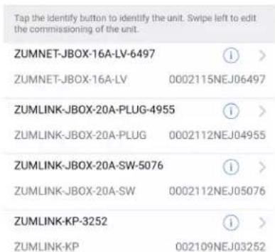
text_image
Tap the identify button to identify the unit. Swipe left to edit the commissioning of the unit. ZUMNET-JBOX-16A-LV-6497 ZUMNET-JBOX-16A-LV 0002115NEJ06497 ZUMLINK-JBOX-20A-PLUG-4955 ZUMLINK-JBOX-20A-PLUG 0002112NEJ04955 ZUMLINK-JBOX-20A-SW-5076 ZUMLINK-JBOX-20A-SW 0002112NEJ05076 ZUMLINK-KP-3252 ZUMLINK-KP 002109NEJ03252- Tap the Identify icon to identify a device. A load controller emits a sound and the Link LED flashes. The connected loads also flash. A keypad flashes its LED.
-
Tap the device to edit or review the device details: Edit Name. Review the Model, Serial Number, Status, and edit the device settings.
-
Current Template Settings: Choose Open room template, Save room template, or Share room template.

text_image
Current Template Tap the buttons below to perform actions with the room template. Open room template > Save room template > Share room template >6. Configuration Data:
- Save room configuration: Save the room configuration data in the space.
- Share room configuration: Share the room configuration data in the space.
- Send configuration to room: Send room logic changes made in the app to the room.
- Advanced data management: Review the Map, Logic, and Settings of the data currently loaded. Load, save or share new Map, Logic, or Settings data.
Tap the button below to perform the respective action on the room configuration.
Save room configuration
Share room configuration
Tap the button to send current configuration to the room.
Send configuration to room
Tap the advanced data management button to perform advanced data file actions. Recommended for advanced users.
Advanced data management
NOTE: Changes made in the app are not sent to the room until they are deployed using the Send configuration to room button.
- Revert changes: Restore all non-deployed changes made since launching the app.

text_image
Tap the revert changes button to restore all data to previous. The app will exit the room. Revert changes 2115NEJ06497-ZUMNET-...Update Firmware with the Zūm App
Follow the required work flow to update device firmware for a Zūm space. Each Zūm space must be updated separately.
- Load the Latest Firmware to the App on page 164
- Update Firmware for a Zūm Space on page 165
Load the Latest Firmware to the App
If new firmware is detected when connecting to the Zūm app, the Room Firmware window appears on the Nearby Rooms screen.

text_image
Nearby Rooms Swipe down to refresh. Swipe right from the left screen edge to show the Help menu. Tap on any of the rooms below to pair with it. 2131NEJ06972-ZUMNET-JBOX-1... Signal Strength >60 2121NEJ11176-ZUMNET-JBOX-D... Signal Strength >66 Room Firmware New release is available Download Firmware v1.03.42Tap Download Firmware to load the firmware to the app. The Room Firmware window message changes when the firmware is successfully downloaded. The Zūm app is now ready to connect to the Zūm space and start updating outdated devices.
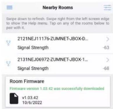
text_image
Nearby Rooms Swipe down to refresh. Swipe right from the left screen edge to show the Help menu. Tap on any of the rooms below to pair with it. 2121NEJ11176-ZUMNET-JBOX-D... Signal Strength - 63 2131NEJ06972-ZUMNET-JBOX-1... Signal Strength - 68 Room Firmware Firmware version 1.03.42 was successfully downloaded v1.03.42 10/6/2022Update Firmware for a Zūm Space
WARNING: Interrupting the firmware update can cause the update to fail. To avoid interrupting the firmware update, follow these best practices:
- Place the mobile device in Do Not Disturb Mode.
- Do not minimize or place the Zūm app in the background.
- Do not lock the mobile device.
To update device firmware in a Zūm space.
- Choose the desired Zūm space to access the Main screen and tap Firmware.
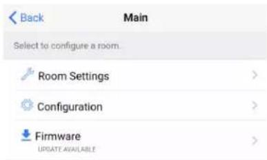
text_image
Back Main Select to configure a room. Room Settings > Configuration > Firmware UPDATE AVAILABLE >- Tap Update Now to initiate the firmware update for STEP 1. Devices are grouped based on the device type.
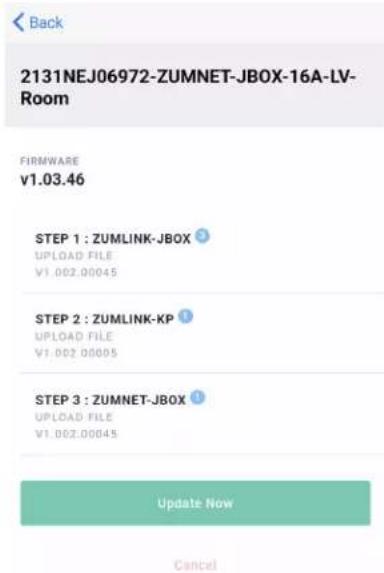
text_image
2131NEJ06972-ZUMNET-JBOX-16A-LV-Room FIRMWARE v1.03.46 STEP 1 : ZUMLINK-JBOX UPLOAD FILE v1.002.00045 STEP 2 : ZUMLINK-KP UPLOAD FILE v1.002.00005 STEP 3 : ZUMNET-JBOX UPLOAD FILE v1.002.00045 Update Now CancelNOTE: The number next to the device type indicates the number of devices of that type that need to be updated in that Zūm space.
- When the Update Firmware confirmation displays, select Yes to continue or No to cancel and return to Firmware. The confirmation also estimates the amount of time it will take to update the room based on the number of devices.
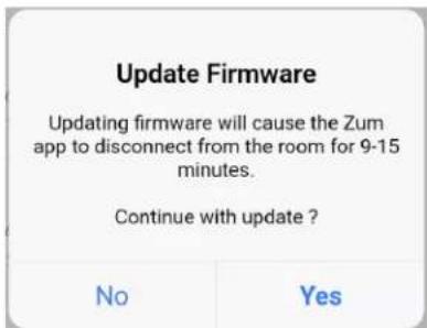
text_image
Update Firmware Updating firmware will cause the Zum app to disconnect from the room for 9-15 minutes. Continue with update ? No YesNOTE: The Zūm space is inaccessible via Bluetooth until the firmware update process is complete.
- When all of the devices are updated in a Zūm space, a notification displays stating the update is complete. Click OK, and repeat the process for every Zūm space listed in Nearby Rooms.
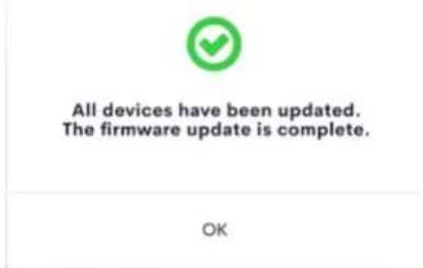
text_image
All devices have been updated. The firmware update is complete. OK- If a device fails to update, a notification opens stating that some of the devices were not updated. Click OK.
The notification closes and displays the Nearby Rooms screen. To restart the firmware update, select the room and repeat the procedure from step 1 until all of the devices have been successfully updated.
Load Controllers Zūm App Configuration
The following sections describe Züm app configuration for the ZUMNET-JBOX-16A-LV, ZUMLINK-JBOX-16A-LV, ZUMLINK-JBOX-20A-PLUG, and ZUMLINK-JBOX-20A-SW load controllers.
For the ZUMNET-JBOX-DALI and ZUMLINK-EXP-16A-DIMU load controllers, refer to DALI Load Controller Züm App Configuration on page 176 and Universal Dimmer Load Controller Züm App Configuration on page 198.
Zūm App Main Screen
From the Nearby Rooms screen, tap the desired room to open the Main screen. The following sections describe the actions available for each area of the Main screen.

text_image
Back Main Select to configure a room. Room Settings > Configuration > Firmware UPDATE AVAILABLE > Tap the identify button to identify the unit. Swipe left to edit the commissioning of the unit. ZUMLINK-EXP-16A-DIMU-2789 ZUMLINK-EXP-16A-DIMU 0002115NEJ06497 ZUMNET-JBOX-16A-LV-6497 ZUMNET-JBOX-16A-LV 0002115NEJ06497 ZUMLINK-JBOX-20A-PLUG-4955 ZUMLINK-JBOX-20A-PLUG 0002112NEJ04955 ZUMLINK-JBOX-20A-SW-5076 ZUMLINK-JBOX-20A-SW 0002112NEJ05076 ZUMLINK-KP-3252 ZUMLINK-KP 002109NEJ03252 Current Template Tap the button below to perform the respective action on the room template. Open room template > Save room template > Share room template > Tap the button below to perform the respective action on the room configuration. Save room configuration > Share room configuration > Tap the button to send current configuration to the room. Send configuration to room Tap the advanced data management button to perform advanced data file actions. Recommended for advanced users. Advanced data management > Tap the revert changes button to restore all data to previous. The app will exit the room. Revert changesNOTE: The numbers below correspond with the numbers in the Main screen diagram.
-
Room Settings: Edit the Room Name, PIN, Floor ID, Zone ID, and Network information.
-
Configuration: Edit the room logic to view the current state of the room.
-
Occupancy Sensors: View details for the connected sensor(s) or edit the sensor name.
- Photo Sensors: View details for the connected sensor(s) or edit the sensor name.
- Load Controllers: Identify and view details for the connected load controller(s).
- ZUMLINK-JBOX-16A-LV and ZUMNET-JBOX-16A-LV load controllers:
■ View Current Scene, Daylighting status, and Output Level.
■ Override: The state of the load when Override is recalled. Click the toggle to turn the load on or off during Override.
- Assign the occupancy mode (Occupancy menu), vacancy mode (Vacancy menu), vicinity mode (Vicinity menu), and daylight harvesting (Photo menu) to specific load controllers.
■ View Dimming Values
■ Edit the Dimming Curve Configuration or Dimmer Scenes Configuration.
- ZUMLINK-JBOX-20A-PLUG load controller:
■ Override: The state of the load when Override is recalled. Click the toggle to turn the load on or off during Override.
- Assign the occupancy mode (Occupancy menu), vacancy mode (Vacancy menu), vicinity mode (Vicinity menu), and daylight harvesting (Photo menu) to specific load controllers.
- ZUMLINK-JBOX-20A-SW load controller:
■ Closed: Click the toggle to turn the load on or off.
■ Override: The state of the load when Override is recalled. Click the toggle to turn the load on or off during Override.
- Assign the occupancy mode (Occupancy menu), vacancy mode (Vacancy menu), vicinity mode (Vicinity menu), and daylight harvesting (Photo menu) to specific load controllers.
■ Scenes: Allow keypad access to the scene by selecting or deselecting the checkbox. Determine the state of the load when the scene is recalled by clicking the toggle on or off.
- ZUMLINK-EXP-16A-DIMU load controller:
■ View Current Scene, Daylighting status, and Output Level.
- Override: The state of the load when Override is recalled. Click the toggle to turn the load on or off during Override.
- Assign the occupancy mode (Occupancy menu), vacancy mode (Vacancy menu), vicinity mode (Vicinity menu), and daylight harvesting (Photo menu) to specific load controllers.
■ View Dimming Values.
■ Edit the Dimmer Scenes Configuration.
- Scenes: View and edit room scenes: Scene 1 - Scene 16. When editing the scene, tap the Identify icon to identify the load controller. The load controller emits a sound and flashes the Link LED. The connected loads also flash.
- Keypads: Identify and view details for the connected keypad(s). Edit the keypad name and assign the button layout.
° Adjust the Double Tap Speed: Set the amount of time between two button presses to qualify as a double tap.
- Specify the Button Layout and click on a button to configure button actions. Button action options:
■ None
■ Off: Assigned load controllers turn off.
■ On: Assigned loads turn on.
■ Raise: Assigned load controllers raise.
■ Toggle: Switches load controllers between ON and OFF states
■ Lower: Assigned load controllers lower.
■ Recall Scene 1 - Scene 16: Assigned load controllers recall the behavior set for the specified scene.
- Export to Hub: Name and send information to ZUM-HUB4 for macro actions.
- Load Shedding: Set the maximum levels for load shedding.
- Load/Sensor Groups: Create groups within the room.
- DALI Controllers: Address drivers, create DALI groups, assign drivers, and identify drivers.
- Current Scene: Displays the current room scene.
-
Occupancy Status: Displays occupied or vacant. If any area of the room is occupied, then the status is Occupied. When all areas of the room are vacant, the status is Vacant.
-
Firmware: To update firmware, refer to Update Firmware with the Züm App on page 164..
-
Discovered Room Devices: Identify a device and edit the commissioning settings

text_image
Tap the identify button to identify the unit. Swipe left to edit the commissioning of the unit. ZUMNET-JBOX-16A-LV-6497 ZUMNET-JBOX-16A-LV 0002115NEJ06497 ZUMLINK-JBOX-20A-PLUG-4955 ZUMLINK-JBOX-20A-PLUG 0002112NEJ04955 ZUMLINK-JBOX-20A-SW-5076 ZUMLINK-JBOX-20A-SW 0002112NEJ05076 ZUMLINK-KP-3252 ZUMLINK-KP 002109NEJ03252- Tap the Identify icon to identify a device. A load controller emits a sound and the Link LED flashes. The connected loads also flash. A keypad flashes its LED.
-
Tap the device to edit or review the device details: Edit Name. Review the Model, Serial Number, Status, and edit the device settings.
-
Current Template Settings: Choose Open room template, Save room template, or Share room template.

text_image
Current Template Tap the buttons below to perform actions with the room template. Open room template > Save room template > Share room template >- Configuration Data:
- Save room configuration: Save the room configuration data in the space.
- Share room configuration: Share the room configuration data in the space.
- Send configuration to room: Send room logic changes made in the app to the room.
- Advanced data management: Review the Map, Logic, and Settings of the data currently loaded. Load, save or share new Map, Logic, or Settings data.
Tap the button below to perform the respective action on the room configuration.
Save room configuration
Share room configuration
Tap the button to send current configuration to the room.
Send configuration to room
Tap the advanced data management button to perform advanced data file actions. Recommended for advanced users.
Advanced data management
NOTE: Changes made in the app are not sent to the room until they are deployed using the Send configuration to room button.
- Revert changes: Restore all non-deployed changes made since launching the app.
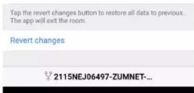
text_image
Tap the revert changes button to restore all data to previous. The app will exit the room. Revert changes 2115NEJ06497-ZUMNET-...Calibrate Daylighting Settings
The photocell component of a Zūm Net load controller, Zūm Link load controller, or Zūm Link universal dimmer load controller detects the amount of ambient light in the room. When a space is calibrated for Daylighting and Scene 1 is called, the photocell will detect the ambient light levels and dim the lights accordingly.
Calibrating Daylighting requires four main steps:
- Assign the photocell component of a load controller to the load controller.
- Send the new configuration to the space.
- Adjust the light level in the space.
- Calibrate Daylighting.
To calibrate the daylight settings:
- Assign the photocell component to the load controller that will participate in Daylighting.
a. From the Main screen, click Configuration.

text_image
Back Main Select to configure a room. Room Settings Configuration Firmware UPDATE AVAILABLEb. Click Load Controllers.

text_image
Back Configuration Select item to configure. Occupancy Sensors > Photo Sensors > Load Controllers > Scenes >c. Click the desired load controller.
d. For Photo, select a photocell from the drop-down menu.

text_image
Back ZUMLINK-JBOX-16A-LV SN: 0002133NEJ10536; FW: v1.001.00054 Current Scene 1 Daylighting Inactive Output Level 68% Tap below to configure the load override. Override (0-100%) 100 Select the sensors that are bound to this load controller. Occupancy All Vacancy All Vicinity None Photo None- Send the configuration to the room.
a. Navigate back to the Main screen.
b. Click Send configuration to room.
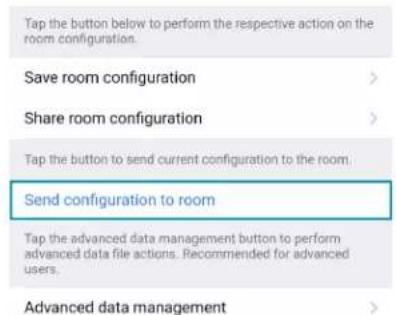
text_image
Tap the button below to perform the respective action on the room configuration. Save room configuration > Share room configuration > Tap the button to send current configuration to the room. Send configuration to room Tap the advanced data management button to perform advanced data file actions. Recommended for advanced users. Advanced data management >A confirmation window opens stating that the app will disconnect from the room. Click OK to continue or Cancel to close without sending the configuration. The Retrieving Data Map screen displays.
- Recall Scene 1 and adjust load levels.
a. From the Main screen, click Configuration.

text_image
Back Main Select to configure a room. Room Settings Configuration Firmware UPDATE AVAILABLEb. Click Scenes.
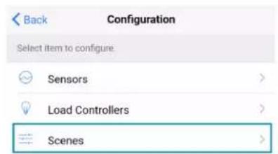
text_image
Back Configuration Select item to configure Sensors > Load Controllers > Scenes >c. Select Scene 1. Daylighting is only available for Scene 1.

text_image
Back Scene 1 Please tap on the values or move the sliders to configure the load controllers levels for the scene. Load 1 (%) 68 ⓘ Load 2 ⓘ Load 3 (%) 100 ⓘ Save current levels Restore original levelsd. Adjust the loads in the space to the appropriate level based on the amount of natural light.
NOTE: DO NOT click Save current levels.
- Calibrate Daylighting.
a. Navigate back to the Main screen.
b. Click Room Settings.

text_image
Back Main Select to configure a room. Room Settings Configuration Firmware UPDATE AVAILABLEc. Click Daylight Properties.

text_image
Back Room Settings Tap below to change the room name and the security pin number Name 2131NEJ06972-ZUMNET-JBOX-16A-LV-R PIN Number **** > Floor ID Disabled Zone ID Disabled Save settings changes You can configure your network below Network > Daylight Properties >d. Click Calibrate Daylighting.

text_image
Back Daylight Properties Current Daylight properties of the room Scene 1 Room Occupancy Occupied Calibrate daylightingDuring Daylight calibration, the lights in the space will turn full on, turn off, and then back on with the Daylighting settings. Whenever Scene 1 is recalled, the Daylighting settings are initiated.
DALI Load Controller Zūm App Configuration
The following sections describe Züm app configuration for the ZUMNET-JBOX-DALI load controller.
Zūm App Main Screen
From the Nearby Rooms screen, tap the desired room to open the Main screen. The following sections describe the actions available for each area of the Main screen.

text_image
Back Main Select to configure a room. Room Settings > Configuration > Firmware UPDATE AVAILABLE > Tap the identify button to identify the unit. Swipe left to edit the commissioning of the unit. ZUMLINK-EXP-16A-DIMU-2789 ZUMLINK-EXP-16A-DIMU 0002115NEJ06497 ZUMNET-JBOX-16A-LV-6497 ZUMNET-JBOX-16A-LV 0002115NEJ06497 ZUMLINK-JBOX-20A-PLUG-4955 ZUMLINK-JBOX-20A-PLUG 0002112NEJ04955 ZUMLINK-JBOX-20A-SW-5076 ZUMLINK-JBOX-20A-SW 0002112NEJ05076 ZUMLINK-KP-3252 ZUMLINK-KP 002109NEJ03252 Current Template Tap the button below to perform the respective action on the room template. Open room template > Save room template > Share room template > Tap the button below to perform the respective action on the room configuration. Save room configuration > Share room configuration > Tap the button to send current configuration to the room. Send configuration to room Tap the advanced data management button to perform advanced data file actions. Recommended for advanced users. Advanced data management > Tap the revert changes button to restore all data to previous. The app will exit the room. Revert changes ① ② ③ ④ ⑤ ⑥ ⑦NOTE: The numbers below correspond with the numbers in the Main screen diagram.
-
Room Settings: Edit the Room Name, PIN, Floor ID, Zone ID, and Network information.
-
Configuration: Edit the room logic to view the current state of the room.
-
Occupancy Sensors: View details for the connected sensor(s) or edit the sensor name.
- Photo Sensors: View details for the connected sensor(s) or edit the sensor name.
- Load Controllers: Identify and view details for the connected load controller(s).
- ZUMLINK-JBOX-16A-LV and ZUMNET-JBOX-16A-LV load controllers:
■ View Current Scene, Daylighting status, and Output Level.
■ Override: The state of the load when Override is recalled. Click the toggle to turn the load on or off during Override.
- Assign the occupancy mode (Occupancy menu), vacancy mode (Vacancy menu), vicinity mode (Vicinity menu), and daylight harvesting (Photo menu) to specific load controllers.
■ View Dimming Values
■ Edit the Dimming Curve Configuration or Dimmer Scenes Configuration.
- ZUMLINK-JBOX-20A-PLUG load controller:
■ Override: The state of the load when Override is recalled. Click the toggle to turn the load on or off during Override.
- Assign the occupancy mode (Occupancy menu), vacancy mode (Vacancy menu), vicinity mode (Vicinity menu), and daylight harvesting (Photo menu) to specific load controllers.
- ZUMLINK-JBOX-20A-SW load controller:
■ Closed: Click the toggle to turn the load on or off.
- Override: The state of the load when Override is recalled. Click the toggle to turn the load on or off during Override.
- Assign the occupancy mode (Occupancy menu), vacancy mode (Vacancy menu), vicinity mode (Vicinity menu), and daylight harvesting (Photo menu) to specific load controllers.
■ Scenes: Allow keypad access to the scene by selecting or deselecting the checkbox. Determine the state of the load when the scene is recalled by clicking the toggle on or off.
- ZUMLINK-EXP-16A-DIMU load controller:
■ View Current Scene, Daylighting status, and Output Level.
- Override: The state of the load when Override is recalled. Click the toggle to turn the load on or off during Override.
- Assign the occupancy mode (Occupancy menu), vacancy mode (Vacancy menu), vicinity mode (Vicinity menu), and daylight harvesting (Photo menu) to specific load controllers.
■ View Dimming Values.
■ Edit the Dimmer Scenes Configuration.
- Scenes: View and edit room scenes: Scene 1 - Scene 16. When editing the scene, tap the Identify icon to identify the load controller. The load controller emits a sound and flashes the Link LED. The connected loads also flash.
- Keypads: Identify and view details for the connected keypad(s). Edit the keypad name and assign the button layout.
° Adjust the Double Tap Speed: Set the amount of time between two button presses to qualify as a double tap.
- Specify the Button Layout and click on a button to configure button actions. Button action options:
■ None
■ Off: Assigned load controllers turn off.
■ On: Assigned loads turn on.
■ Raise: Assigned load controllers raise.
■ Toggle: Switches load controllers between ON and OFF states
■ Lower: Assigned load controllers lower.
■ Recall Scene 1 - Scene 16: Assigned load controllers recall the behavior set for the specified scene.
- Export to Hub: Name and send information to ZUM-HUB4 for macro actions.
- Load Shedding: Set the maximum levels for load shedding.
- Load/Sensor Groups: Create groups within the room.
- DALI Controllers: Address drivers, create DALI groups, assign drivers, and identify drivers.
- Current Scene: Displays the current room scene.
-
Occupancy Status: Displays occupied or vacant. If any area of the room is occupied, then the status is Occupied. When all areas of the room are vacant, the status is Vacant.
-
Firmware: To update firmware, refer to Update Firmware with the Züm App on page 164..
-
Discovered Room Devices: Identify a device and edit the commissioning settings

text_image
Tap the identify button to identify the unit. Swipe left to edit the commissioning of the unit. ZUMNET-JBOX-16A-LV-6497 ZUMNET-JBOX-16A-LV 0002115NEJ06497 ZUMLINK-JBOX-20A-PLUG-4955 ZUMLINK-JBOX-20A-PLUG 0002112NEJ04955 ZUMLINK-JBOX-20A-SW-5076 ZUMLINK-JBOX-20A-SW 0002112NEJ05076 ZUMLINK-KP-3252 ZUMLINK-KP 002109NEJ03252- Tap the Identify icon to identify a device. A load controller emits a sound and the Link LED flashes. The connected loads also flash. A keypad flashes its LED.
-
Tap the device to edit or review the device details: Edit Name. Review the Model, Serial Number, Status, and edit the device settings.
-
Current Template Settings: Choose Open room template, Save room template, or Share room template.

text_image
Current Template Tap the buttons below to perform actions with the room template. Open room template > Save room template > Share room template >6. Configuration Data:
- Save room configuration: Save the room configuration data in the space.
- Share room configuration: Share the room configuration data in the space.
- Send configuration to room: Send room logic changes made in the app to the room.
- Advanced data management: Review the Map, Logic, and Settings of the data currently loaded. Load, save or share new Map, Logic, or Settings data.
Tap the button below to perform the respective action on the room configuration.
Save room configuration
Share room configuration
Tap the button to send current configuration to the room.
Send configuration to room
Tap the advanced data management button to perform advanced data file actions. Recommended for advanced users.
Advanced data management
NOTE: Changes made in the app are not sent to the room until they are deployed using the Send configuration to room button.
- Revert changes: Restore all non-deployed changes made since launching the app.
text_image
Tap the revert changes button to restore all data to previous. The app will exit the room. Revert changes 2115NEJ06497-ZUMNET-...Calibrate Daylighting Settings
The photocell component of a Zūm Net load controller, Zūm Link load controller, or Zūm Link universal dimmer load controller detects the amount of ambient light in the room. When a space is calibrated for Daylighting and Scene 1 is called, the photocell will detect the ambient light levels and dim the lights accordingly.
Calibrating Daylighting requires four main steps:
- Assign the photocell component of a load controller to the load controller.
- Send the new configuration to the space.
- Adjust the light level in the space.
- Calibrate Daylighting.
To calibrate the daylight settings:
- Assign the photocell component to the load controller that will participate in Daylighting.
a. From the Main screen, click Configuration.
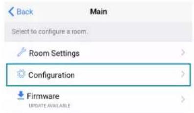
text_image
Back Main Select to configure a room. Room Settings Configuration Firmware UPDATE AVAILABLEb. Click Load Controllers.

text_image
Back Configuration Select item to configure. Occupancy Sensors > Photo Sensors > Load Controllers > Scenes >c. Click the desired load controller.
d. For Photo, select a photocell from the drop-down menu.
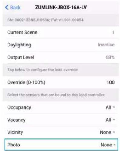
text_image
Back ZUMLINK-JBOX-16A-LV SN: 0002133NEJ10536; FW: v1.001.00054 Current Scene 1 Daylighting Inactive Output Level 68% Tap below to configure the load override. Override (0-100%) 100 Select the sensors that are bound to this load controller. Occupancy All Vacancy All Vicinity None Photo None- Send the configuration to the room.
a. Navigate back to the Main screen.
b. Click Send configuration to room.

text_image
Tap the button below to perform the respective action on the room configuration. Save room configuration > Share room configuration > Tap the button to send current configuration to the room. Send configuration to room Tap the advanced data management button to perform advanced data file actions. Recommended for advanced users. Advanced data management >A confirmation window opens stating that the app will disconnect from the room. Click OK to continue or Cancel to close without sending the configuration. The Retrieving Data Map screen displays.
- Recall Scene 1 and adjust load levels.
a. From the Main screen, click Configuration.

text_image
Back Main Select to configure a room. Room Settings Configuration Firmware UPDATE AVAILABLEb. Click Scenes.

text_image
Back Configuration Select item to configure Sensors > Load Controllers > Scenes >c. Select Scene 1. Daylighting is only available for Scene 1.

text_image
Back Scene 1 Please tap on the values or move the sliders to configure the load controllers levels for the scene. Load 1 (%) 68 ⓘ Load 2 ⓘ Load 3 (%) 100 ⓘ Save current levels Restore original levelsd. Adjust the loads in the space to the appropriate level based on the amount of natural light.
NOTE: DO NOT click Save current levels.
- Calibrate Daylighting.
a. Navigate back to the Main screen.
b. Click Room Settings.

text_image
Back Main Select to configure a room. Room Settings Configuration Firmware UPDATE AVAILABLEc. Click Daylight Properties.

text_image
Back Room Settings Tap below to change the room name and the security pin number Name 2131NEJ06972-ZUMNET-JBOX-16A-LV-R PIN Number **** > Floor ID Disabled Zone ID Disabled Save settings changes You can configure your network below Network > Daylight Properties >d. Click Calibrate Daylighting.
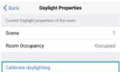
text_image
Back Daylight Properties Current Daylight properties of the room Scene 1 Room Occupancy Occupied Calibrate daylightingDuring Daylight calibration, the lights in the space will turn full on, turn off, and then back on with the Daylighting settings. Whenever Scene 1 is recalled, the Daylighting settings are initiated.
DALI Commissioning
Follow the required work flow for DALI commissioning of a DALI load controller:
- Confirm Operating mode (Load Controllers Züm App Configuration on page 167)
- Address drivers (Load Controllers Züm App Configuration on page 167)
- Create DALI groups (Load Controllers Züm App Configuration on page 167)
NOTE: For DALI Groups mode only. Broadcast mode does not use Groups. Refer to Load Controllers Züm App Configuration on page 167 for more information.
- Assign drivers (Load Controllers Züm App Configuration on page 167)
To begin the commissioning process, tap DALI Controllers in Configuration.
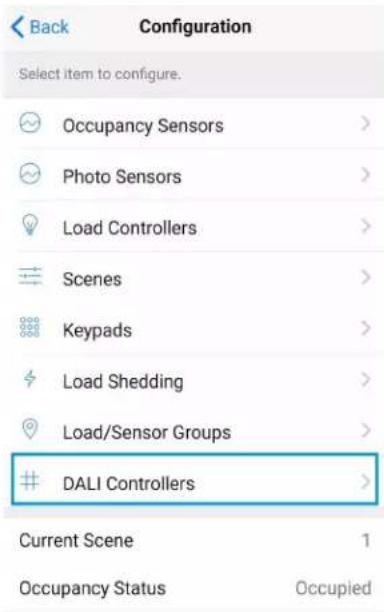
text_image
Back Configuration Select item to configure. Occupancy Sensors > Photo Sensors > Load Controllers > Scenes > Keypads > Load Shedding > Load/Sensor Groups > DALI Controllers > Current Scene 1 Occupancy Status OccupiedTap the desired DALI controller to open the DALI Commissioning screen. The app may not respond until the system fully loads. The DALI Commissioning screen offers the following options:
- Addressing: Address all drivers and discover new drivers.
- Groups: Assign drivers to DALI groups and review DALI group assignments.
NOTE: For DALI Groups mode only. Broadcast mode does not use Groups. Refer to Load Controllers Züm App Configuration on page 167 for more information.
- Drivers: Edit drivers and review their status.
• Diagnostics: Start a diagnostics test and review results. - Email system info report: Send an system report to an email address.

text_image
Back DALI Commissioning Tap to configure Dali Operating Mode Operating mode DALI Groups * Device Discovery and Addressing. Addressing > Groups 0 groups > Drivers 4 drivers > Diagnostics >Email system info report
Operating Mode
DALI Commissioning operates in two modes: Broadcast or DALI Groups. In Broadcast mode, every device connected to the DALI load controller can be controlled in unison. In Groups mode, individual drivers can be placed in groups for granular control over the devices.
To confirm the room's operating mode:
- Navigate to Configuration > DALI Controllers > DALI Commissioning
- Review the DALI Commissioning screen.
- If the Operating mode states DALI Groups or no operating mode is identified, then the DALI load controller is operating in DALI Groups mode.

text_image
Back DALI Commissioning Tap to configure Dali Operating Mode Operating mode DALI Groups -NOTE: If Operating mode is not present on the DALI Commissioning screen, make sure to update to the latest firmware. Refer to Update Firmware with the Züm App on page 164.
- If the Operating mode states Broadcast, then the DALI load controller is operating in Broadcast mode.

text_image
Back DALI Commissioning Tap to configure Dali Operating Mode Operating mode Broadcast *To change the Operating mode:
NOTE: Changing the Operating mode affects keypad programming assignments. Review the assignments after implementing the change.
- Tap the current Operating mode to open the Operating mode menu.

text_image
Back DALI Commissioning Tap to configure Dali Operating Mode Operating mode DALI Groups * Device Discovery and Addressing. Addressing > Groups 0 groups > Drivers 4 drivers > Diagnostics > Email system info report- Select either DALI Groups or Broadcast.
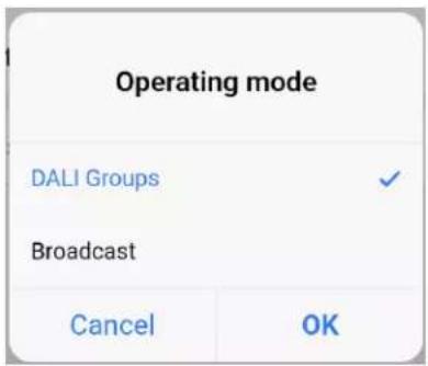
text_image
Operating mode DALI Groups ✓ Broadcast Cancel OK- Tap OK to continue and a warning dialog opens.
- Tap Apply to change the Operating mode or Cancel to close without making a change.

text_image
Changing the DALI Operating Mode will affect programming assignments. Apply CancelAddressing
Use Addressing to discover new drivers for a new or established system.
NOTE: Addressing is required in DALI Groups Operating mode but is optional in Broadcast Operating mode.

text_image
Back Addressing This process will clear all driver information and begin the addressing process. The process may take a few minutes to complete. Best for NEW system Delete and address all This process will search for new drivers and address them. The process may take a few minutes to complete. Best for system additions Address new / Resolve conflictsNew Systems
Tap Delete and Address All to delete any driver information and begin the addressing process. When the confirmation window opens, tap OK to continue or Cancel to exit without readdressing the system.
Established Systems
Tap Address New / Resolve Conflicts to discover new drivers and add them to a system. Each driver must have a unique address. If there are duplicate addresses, resolve the conflict. When the confirmation window opens, tap OK to continue or Cancel to close without addressing the system.
Groups
Use Groups to assign drivers to a DALI group and review DALI group assignments.

text_image
Back Groups Assign Drivers to Groups > Add a groupNOTES:
- For DALI Groups mode only. Broadcast mode does not use Groups. Refer to Load Controllers Züm App Configuration on page 167 for more information.
- DALI groups also appear as load controllers in Configuration > Load Controllers. The DALI groups are inactive until a DALI group has been created in Groups. DALI groups are not the same as load controller groups or occupancy sensor groups.
Assign Drivers to a Group
Tap Assign Drivers to assign a driver to a DALI group.
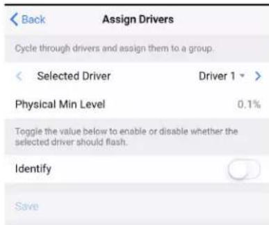
text_image
Back Assign Drivers Cycle through drivers and assign them to a group. Selected Driver Driver 1 > Physical Min Level 0.1% Toggle the value below to enable or disable whether the selected driver should flash. Identify SaveAdd a group
- Selected Driver: Choose a driver to assign. Tap < or > to cycle through the drivers. The Physical Min Level is stated.
The Physical Min Level is the actual level (%) the driver is capable of lowering to. Only Drivers with the same Physical Min Level should be added to the same DALI group. - Identify: Tap the toggle to enable or disable whether the selected driver should flash.
- DALI groups: Tap the check box next to the desired DALI group. Tap Save to save the changes or tap Back to return to the previous screen without saving.
- Add a group: Opens the same screen as Load Controllers Züm App Configuration on page 167.
Add a Group
Tap Save to save the DALI group.
| Back | Add A Group |
| Group Name | |
| DALI Group Assigned | 0 |
| Save | |
The previous screen appears with the new DALI group listed under Group Assignments.
| Back | Groups |
| Assign Drivers to Groups | |
| Group Assignments | |
| View groups below. Select to modify. | |
| ZUMNET-JBOX-DALI-1176-101 | i |
| 0 drivers | |
| Add a group | |
Group Assignments
Created DALI groups are listed under Group Assignments. To flash drivers, tap the Identify icon i next to Drivers in group to flash all drivers in the group or next to a driver to identify a single driver.
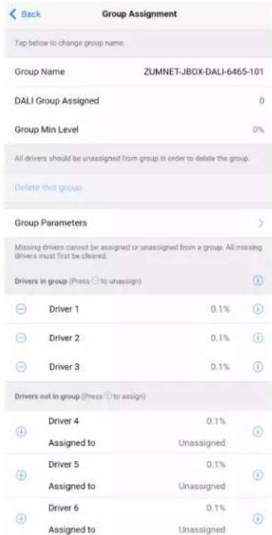
text_image
Back Group Assignment Tap below to change group name. Group Name ZUMNET-JBOX-DALI-6465-101 DALI Group Assigned 0 Group Min Level 0% All drivers should be unassigned from group in order to delete the group. Delete this group Group Parameters Missing drivers cannot be assigned or unassigned from a group. All missing drivers must first be cleaned. Drivers in group (Press ☑ to unassign) Driver 1 0.1% Driver 2 0.1% Driver 3 0.1% Drivers not in group (Press ☑ to assign) Driver 4 0.1% Assigned to Unassigned Driver 5 0.1% Assigned to Unassigned Driver 6 0.1% Assigned to Unassigned- Group Name: Tap to edit the DALI group name.
After editing the Group Name, save the new name by tapping the go or enter button on your phone's keyboard or tapping outside of the Group Name field.
• DALI Group Assigned: Displays the group number of the DALI group. - Group Min Level: Displays the value set in View Dimming Properties > Min Level (0-45%).
- Delete this Group: Tap to delete the DALI group.
Delete this Group is only enabled after all drivers are removed from the group.
- Group Parameters: Tap to access the Group Parameters.
| Back | ZUMNET-JBOX-DALI-6465-101 |
| SN: 000212SNEJ86465; FW: v1.082.00026 | |
| Current Scene | 1 |
| Daylighting | Inactive |
| Output Level | 0% |
| Tap below to configure the load override. | |
| Override (0-100%) | 100 |
| Select the sensors that are bound in this load controller. | |
| Occupancy | All → |
| Vacancy | All → |
| Vicinity | None → |
| Photo | None → |
| Tap the button below to view the dimmer properties | |
| View Dimmer Values | > |
| Tap the button below to configure the dimmer scene properties | |
| Edit Dimmer Scenes Configuration | > |
- Current scene
Daylighting - Output Level
○ Override
Occupancy
Vacancy - Vicinity
- Photo
- View Dimmer Values
| Back | Dimming Properties |
| Calibration for night time | |
| Dim Level | 0% |
| Sensor Reading | 0 |
| Use slider below to adjust the Output Level | |
| Output Level (%) | 0 |
| Tap on value to set the power on, minimum and maximum levels | |
| Power on Level (0-100%) | 0 |
| Min Level (0-45%) | 0 |
| Max Level (55-100%) | 100 |
| Tap on value to set the rate light level change and the fade time for recalling a scene | |
| Fade Rate (0.25-10.00 secs) | 3 |
| Fade Time (0.25-30.00 secs) | 1 |
| Tap on value to set the time that it takes to fade the light level from current level to ON or OFF | |
| On Fade Time (0.25-30.00 secs) | 1 |
| Off Fade Time (0.25-30.00 secs) | 1 |
■ Dim Level: Review the dimming level set for day and night calibration.
■ Sensor Reading: Review the sensor reading intensity for day and night calibration.
■ Output Level: Use the slider to adjust the Output level.
■ Power on Level (0-100%): Set the light level when powering On.
■ Min Level (0-45%): Set the minimum light level threshold a driver cannot pass.
■ Max Level (55-100%): Set the maximum light level threshold a driver cannot pass.
- Fade Rate (0.25-10.00 secs): Set the amount of time it takes to raise the light level from 0% to 100% or dim the level from 100% to 0% when pressing the raise or lower buttons on a keypad.
■ Fade Time (0.25-30.00 secs): Set the amount of time to fade from the current light level to a recalled scene or discrete level.
- On Fade Time (0.25-30.00 secs): Set the amount of time to fade from the current light level to the On scene.
- Off Fade Time (0.25-30.00 secs): Set the amount of time to fade from the current light level to the Off scene.
- Edit Dimmer Scene Configurations. Tap on the value or move the sliders to configure levels for each scene. To exclude scenes from participating in the group, uncheck the box next to the scene.
- Drivers in group and Drivers not in group: Tap + to add a driver to the DALI group or tap - to remove a driver from the DALI group.
Drivers
Use the Drivers screen to review the Drivers List.
| Back | Driver List | |
| Addressed Drivers | 4 | 1 |
| Missing Drivers | 0 | |
| Ungrouped drivers detected. Go to Group to resolve. | ||
| Clear all missing drivers | ||
| Tap on driver entry to modify. | ||
| DALI Addr | 00 | |
| Group | ZUMNET-JBOX-DALI-Fr... | i > |
| Status | Off | |
| DALI Addr | 01 | |
| Group | Unassigned | i > |
| Status | On | |
| DALI Addr | 02 | |
| Group | Unassigned | i > |
| Status | On | |
| DALI Addr | 03 | |
| Group | Unassigned | i > |
| Status | On | |
- Addressed Drivers: States the number of drivers addressed.
- Missing Drivers: States the number of drivers missing. Missing drivers are drivers that were previously addressed but currently can not be found.
The Status is displayed as Missing in red to indicate which driver needs to be checked.
- If drivers have been addressed but not assigned to a DALI group, the message "Unassigned drivers detected. Go to Groups to resolve." appears. Drivers must be assigned to a DALI group before they can be controlled.
- If missing drivers are detected, Clear all missing drivers is active. Tap Clear all missing drivers to delete the addressed information. Return to Addressing and tap Address New / Resolve Conflicts.
- Drivers listed: Each listed driver states the DALI Address number (00-63), the Group name or Unassigned, and the Status (On, Off, or Missing).
Tap the Identify icon. The drivers flash, identifying the driver.
Tap on the driver to access the Driver Setting.
- Review Driver details such as DALI Address, Long Address, Physical Min Level, Driver Type, and Status.
Change the DALI Address. Chose a number 00-63 and tap Save to save the new address. Only available addresses can be selected. Addresses already assigned to another driver are grayed out and cannot be selected. - Review the name of the group the driver is assigned to and the Min Level Set.
Tap Grouping to access Assign Drivers. The same screen as Load Controllers Züm App Configuration on page 167 opens.
Diagnostics
Use the Diagnostics screen to test the DALI loop for the selected DALI controller.

text_image
Back Diagnostics Ping Test This process will query all addresses and analyze the response. The process may take a few minutes to complete. Start diagnostics test >Tap Start diagnostics test to begin a Ping Test. The test pings each driver ten times to trigger a response and report the following data:
- Status of bus voltage
• Number of drivers that passed
• Number of drivers that failed
• Presence of unassigned drivers

text_image
Back Diagnostics Ping Test 100% Abort test Test results details Bus Voltage Ok Drivers that Passed 4 ① Drivers that Failed 0 Unaddressed Drivers NoneTap Test result details to view the driver address and how many times out of 10 the driver did not respond to a ping.

Back
Diagnostics
| DALI Addr | 07 | √ |
| DALI Addr | 08 | √ |
| DALI Addr | 09 | √ |
| DALI Addr | 10 | √ |
| DALI Addr | 11 | √ |
| DALI Addr | 12 | √ |
| DALI Addr | 13 | √ |
| DALI Addr | 14 | √ |
| DALI Addr | 15 | 1 |
| No Response | 10/10 | |
| DALI Addr | 16 | 1 |
| No Response | 10/10 | |
| DALI Addr | 17 | 1 |
| No Response | 10/10 | |
| DALI Addr | 18 | 1 |
| No Response | 10/10 | |
| DALI Addr | 19 | 1 |
| No Response | 10/10 |
Universal Dimmer Load Controller Zūm App Configuration
The following sections describe Züm app configuration for the ZUMLINK-EXP-16A-DIMU universal dimmer load controller.
Zūm App Main Screen
From the Nearby Rooms screen, tap the desired room to open the Main screen. The following sections describe the actions available for each area of the Main screen.

text_image
Back Main Select to configure a room. Room Settings > Configuration > Firmware UPDATE AVAILABLE > Tap the identify button to identify the unit. Swipe left to edit the commissioning of the unit. ZUMLINK-EXP-16A-DIMU-2789 ZUMLINK-EXP-16A-DIMU 0002115NEJ06497 ZUMNET-JBOX-16A-LV-6497 ZUMNET-JBOX-16A-LV 0002115NEJ06497 ZUMLINK-JBOX-20A-PLUG-4955 ZUMLINK-JBOX-20A-PLUG 0002112NEJ04955 ZUMLINK-JBOX-20A-SW-5076 ZUMLINK-JBOX-20A-SW 0002112NEJ05076 ZUMLINK-KP-3252 ZUMLINK-KP 002109NEJ03252 Current Template Tap the button below to perform the respective action on the room template. Open room template > Save room template > Share room template > Tap the button below to perform the respective action on the room configuration. Save room configuration > Share room configuration > Tap the button to send current configuration to the room. Send configuration to room Tap the advanced data management button to perform advanced data file actions. Recommended for advanced users. Advanced data management > Tap the revert changes button to restore all data to previous. The app will exit the room. Revert changes ① ② ③ ④ ⑤ ⑥ ⑦NOTE: The numbers below correspond with the numbers in the Main screen diagram.
-
Room Settings: Edit the Room Name, PIN, Floor ID, Zone ID, and Network information.
-
Configuration: Edit the room logic to view the current state of the room.
-
Occupancy Sensors: View details for the connected sensor(s) or edit the sensor name.
- Photo Sensors: View details for the connected sensor(s) or edit the sensor name.
- Load Controllers: Identify and view details for the connected load controller(s).
- ZUMLINK-JBOX-16A-LV and ZUMNET-JBOX-16A-LV load controllers:
■ View Current Scene, Daylighting status, and Output Level.
■ Override: The state of the load when Override is recalled. Click the toggle to turn the load on or off during Override.
- Assign the occupancy mode (Occupancy menu), vacancy mode (Vacancy menu), vicinity mode (Vicinity menu), and daylight harvesting (Photo menu) to specific load controllers.
■ View Dimming Values
■ Edit the Dimming Curve Configuration or Dimmer Scenes Configuration.
- ZUMLINK-JBOX-20A-PLUG load controller:
■ Override: The state of the load when Override is recalled. Click the toggle to turn the load on or off during Override.
- Assign the occupancy mode (Occupancy menu), vacancy mode (Vacancy menu), vicinity mode (Vicinity menu), and daylight harvesting (Photo menu) to specific load controllers.
- ZUMLINK-JBOX-20A-SW load controller:
■ Closed: Click the toggle to turn the load on or off.
- Override: The state of the load when Override is recalled. Click the toggle to turn the load on or off during Override.
- Assign the occupancy mode (Occupancy menu), vacancy mode (Vacancy menu), vicinity mode (Vicinity menu), and daylight harvesting (Photo menu) to specific load controllers.
■ Scenes: Allow keypad access to the scene by selecting or deselecting the checkbox. Determine the state of the load when the scene is recalled by clicking the toggle on or off.
- ZUMLINK-EXP-16A-DIMU load controller:
■ View Current Scene, Daylighting status, and Output Level.
- Override: The state of the load when Override is recalled. Click the toggle to turn the load on or off during Override.
- Assign the occupancy mode (Occupancy menu), vacancy mode (Vacancy menu), vicinity mode (Vicinity menu), and daylight harvesting (Photo menu) to specific load controllers.
■ View Dimming Values.
■ Edit the Dimmer Scenes Configuration.
- Scenes: View and edit room scenes: Scene 1 - Scene 16. When editing the scene, tap the Identify icon to identify the load controller. The load controller emits a sound and flashes the Link LED. The connected loads also flash.
- Keypads: Identify and view details for the connected keypad(s). Edit the keypad name and assign the button layout.
° Adjust the Double Tap Speed: Set the amount of time between two button presses to qualify as a double tap.
- Specify the Button Layout and click on a button to configure button actions. Button action options:
■ None
■ Off: Assigned load controllers turn off.
■ On: Assigned loads turn on.
■ Raise: Assigned load controllers raise.
■ Toggle: Switches load controllers between ON and OFF states
■ Lower: Assigned load controllers lower.
■ Recall Scene 1 - Scene 16: Assigned load controllers recall the behavior set for the specified scene.
- Export to Hub: Name and send information to ZUM-HUB4 for macro actions.
- Load Shedding: Set the maximum levels for load shedding.
- Load/Sensor Groups: Create groups within the room.
- DALI Controllers: Address drivers, create DALI groups, assign drivers, and identify drivers.
- Current Scene: Displays the current room scene.
-
Occupancy Status: Displays occupied or vacant. If any area of the room is occupied, then the status is Occupied. When all areas of the room are vacant, the status is Vacant.
-
Firmware: To update firmware, refer to Update Firmware with the Züm App on page 164..
-
Discovered Room Devices: Identify a device and edit the commissioning settings

text_image
Tap the identify button to identify the unit. Swipe left to edit the commissioning of the unit. ZUMNET-JBOX-16A-LV-6497 ZUMNET-JBOX-16A-LV 0002115NEJ06497 ZUMLINK-JBOX-20A-PLUG-4955 ZUMLINK-JBOX-20A-PLUG 0002112NEJ04955 ZUMLINK-JBOX-20A-SW-5076 ZUMLINK-JBOX-20A-SW 0002112NEJ05076 ZUMLINK-KP-3252 ZUMLINK-KP 002109NEJ03252- Tap the Identify icon to identify a device. A load controller emits a sound and the Link LED flashes. The connected loads also flash. A keypad flashes its LED.
-
Tap the device to edit or review the device details: Edit Name. Review the Model, Serial Number, Status, and edit the device settings.
-
Current Template Settings: Choose Open room template, Save room template, or Share room template.

text_image
Current Template Tap the buttons below to perform actions with the room template. Open room template > Save room template > Share room template >6. Configuration Data:
- Save room configuration: Save the room configuration data in the space.
- Share room configuration: Share the room configuration data in the space.
- Send configuration to room: Send room logic changes made in the app to the room.
- Advanced data management: Review the Map, Logic, and Settings of the data currently loaded. Load, save or share new Map, Logic, or Settings data.
Tap the button below to perform the respective action on the room configuration.
Save room configuration
Share room configuration
Tap the button to send current configuration to the room.
Send configuration to room
Tap the advanced data management button to perform advanced data file actions. Recommended for advanced users.
Advanced data management
NOTE: Changes made in the app are not sent to the room until they are deployed using the Send configuration to room button.
- Revert changes: Restore all non-deployed changes made since launching the app.

text_image
Tap the revert changes button to restore all data to previous. The app will exit the room. Revert changes 2115NEJ06497-ZUMNET-...Calibrate Daylighting Settings
The photocell component of a Zūm Net load controller, Zūm Link load controller, or Zūm Link universal dimmer load controller detects the amount of ambient light in the room. When a space is calibrated for Daylighting and Scene 1 is called, the photocell will detect the ambient light levels and dim the lights accordingly.
Calibrating Daylighting requires four main steps:
- Assign the photocell component of a load controller to the load controller.
- Send the new configuration to the space.
- Adjust the light level in the space.
- Calibrate Daylighting.
To calibrate the daylight settings:
- Assign the photocell component to the load controller that will participate in Daylighting.
a. From the Main screen, click Configuration.

text_image
Back Main Select to configure a room. Room Settings Configuration Firmware UPDATE AVAILABLEb. Click Load Controllers.
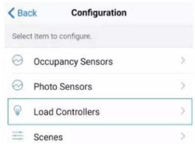
text_image
Back Configuration Select item to configure. Occupancy Sensors > Photo Sensors > Load Controllers > Scenes >c. Click the desired load controller.
d. For Photo, select a photocell from the drop-down menu.

text_image
Back ZUMLINK-JBOX-16A-LV SN: 0002133NEJ10536; FW: v1.001.00054 Current Scene 1 Daylighting Inactive Output Level 68% Tap below to configure the load override. Override (0-100%) 100 Select the sensors that are bound to this load controller. Occupancy All Vacancy All Vicinity None Photo None- Send the configuration to the room.
a. Navigate back to the Main screen.
b. Click Send configuration to room.

text_image
Tap the button below to perform the respective action on the room configuration. Save room configuration > Share room configuration > Tap the button to send current configuration to the room. Send configuration to room Tap the advanced data management button to perform advanced data file actions. Recommended for advanced users. Advanced data management >A confirmation window opens stating that the app will disconnect from the room. Click OK to continue or Cancel to close without sending the configuration. The Retrieving Data Map screen displays.
- Recall Scene 1 and adjust load levels.
a. From the Main screen, click Configuration.

text_image
Back Main Select to configure a room. Room Settings Configuration Firmware UPDATE AVAILABLEb. Click Scenes.

text_image
Back Configuration Select item to configure Sensors > Load Controllers > Scenes >c. Select Scene 1. Daylighting is only available for Scene 1.
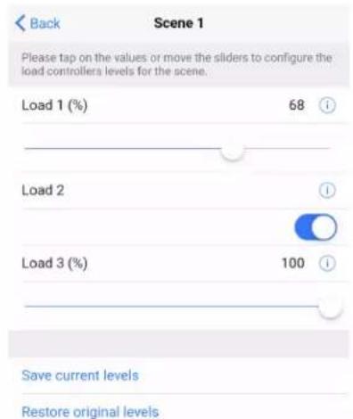
text_image
Back Scene 1 Please tap on the values or move the sliders to configure the load controllers levels for the scene. Load 1 (%) 68 Load 2 Load 3 (%) 100 Save current levels Restore original levelsd. Adjust the loads in the space to the appropriate level based on the amount of natural light.
NOTE: DO NOT click Save current levels.
- Calibrate Daylighting.
a. Navigate back to the Main screen.
b. Click Room Settings.
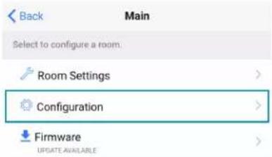
text_image
Back Main Select to configure a room. Room Settings Configuration Firmware UPDATE AVAILABLEc. Click Daylight Properties.
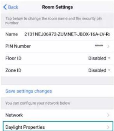
text_image
Back Room Settings Tap below to change the room name and the security pin number Name 2131NEJ06972-ZUMNET-JBOX-16A-LV-R PIN Number **** > Floor ID Disabled Zone ID Disabled Save settings changes You can configure your network below Network > Daylight Properties >d. Click Calibrate Daylighting.

text_image
Back Daylight Properties Current Daylight properties of the room Scene 1 Room Occupancy Occupied Calibrate daylightingDuring Daylight calibration, the lights in the space will turn full on, turn off, and then back on with the Daylighting settings. Whenever Scene 1 is recalled, the Daylighting settings are initiated.
Advanced Properties
Use the Advanced Properties to change the phase and zero-cross settings. To navigate to the Advanced Properties:
- From the Main screen, select Configuration.

text_image
Back Main Select to configure a room. Room Settings Configuration Firmware UPDATE AVAILABLE- Select Load Controllers. A list of load controllers appears.

text_image
Back Configuration Select item to configure. Occupancy Sensors > Photo Sensors > Load Controllers > Scenes >-
Select the universal dimmer from the list of load controllers.
-
Select the universal dimmer load controller component to open the load controller settings.
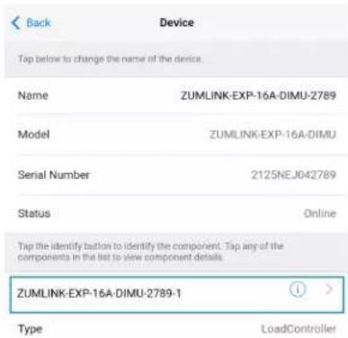
text_image
Back Device Tap below to change the name of the device. Name ZUMLINK-EXP-16A-DIMU-2789 Model ZUMLINK-EXP-16A-DIMU Serial Number 2125NEJ042789 Status Online Tap the identify button to identify the component. Tap any of the components in the list to view component details. ZUMLINK-EXP-16A-DIMU-2789-1 Type LoadController5. Select View Dimmer Values to open the Dimming Properties.
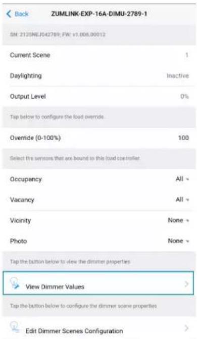
text_image
Back ZUMLINK-EXP-16A-DIMU-2789-1 SN: 2125NEJ042789; FW: v1.006.00012 Current Scene 1 Daylighting Inactive Output Level 0% Tap below to configure the load override. Override (0-100%) 100 Select the sensors that are bound to this load controller. Occupancy All Vacancy All Vicinity None Photo None Tap the button below to view the dimmer properties View Dimmer Values > Tap the button below to configure the dimmer scene properties Edit Dimmer Scenes Configuration6. Select Advanced to open the Advanced Properties.
| Back | Dimming Properties |
| Calibration for day time | |
| Dim Level | 0% |
| Sensor Reading | 0 |
| Calibration for night time | |
| Dim Level | 0% |
| Sensor Reading | 0 |
| Use slider below to adjust the Output Level | |
| Output Level (%) | 0 |
| Tap on value to set the minimum and maximum brightness levels | |
| Min Level (0-45%) | 0 |
| Max Level (55-100%) | 100 |
| Tap on value to set the rate light level change and the fade time for recalling a scene | |
| Fade Rate (0.25-10.00 secs) | 3 |
| Fade Time (0.25-30.00 secs) | 1 |
| Tap on value to set the time that it takes to fade the light level from current level to ON or OFF | |
| On Fade Time (0.25-30.00 secs) | 1 |
| Off Fade Time (0.25-30.00 secs) | 1 |
| Advanced settings | |
| Advanced | > |
Set Phase
WARNINGS:
- Auto Dimming mode should not be disabled unless suggested by a Crestron True Blue Technical Support representative. Incorrectly setting these switches to force the wrong mode can cause damage to the dimmer and lighting fixture or create a hazardous condition.
- Only use Center Dimming mode if instructed by a Crestron True Blue Technical Support representative.
By default, Auto is selected. To change the phase:
- Select the SET PHASE menu to open the options: Forward, Reverse, Center, and Auto.

text_image
Back Advanced Properties Top to configure GMU advanced parameters PHASE: REVERSE (AUTO) SET PHASE Auto ZERO-CROSS FILTERED SET ZERO-CI SET PHASE Filtered Forward Reverse Center Auto Cancel OK- Select the desired option and select OK. The REVERT and APPLY options display.
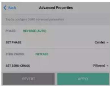
text_image
Back Advanced Properties Top to configure DIM1 advanced parameters PHASE: REVERSE (AUTO) SET PHASE Center > ZERO-CROSS FILTERED SET ZERO-CROSS Filtered > REVERT APPLYa. Select APPLY to apply the change. The dimming performance warning displays requiring a confirmation to apply the change.
Select APPLY to confirm and apply the change, or select Cancel to go back to the previous screen.
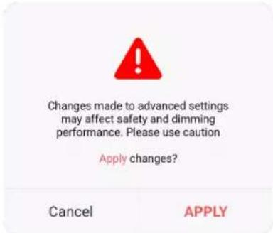
text_image
Changes made to advanced settings may affect safety and dimming performance. Please use caution Apply changes? Cancel APPLYb. Select REVERT to change the selection to the default or previously set phase.
NOTE: If the Back button is selected while changing the Advanced Properties settings, the following warning displays. Select Leave to leave without applying a change or Stay to apply the change.

text_image
Are you sure? Unapplied changes will be discarded if you leave this page. Stay LeaveSet Zero-Cross
By default, Filtered is selected and is strongly recommended for best performance. To change the zero-cross.
- Select the SET ZERO-CROSS menu to open the options: Basic and Filtered.
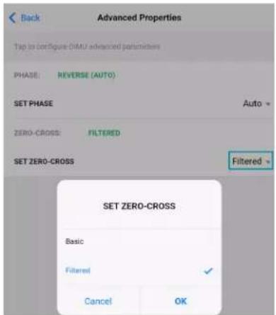
text_image
Back Advanced Properties Tap to Configure DIMU advanced parameters PHASE: REVERSE (AUTO) SET PHASE Auto = ZERO-CROSS FILTERED SET ZERO-CROSS Filtered = SET ZERO-CROSS Basic Filtered Cancel OK- Select the desired option and select OK. The REVERT and APPLY options display.
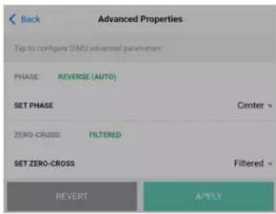
text_image
Back Advanced Properties Top to configure DIMT advanced parameters PHASE: REVERSE (AUTO) SET PHASE Center ZERO-CROSS FILTERED SET ZERO-CROSS Filtered > REVERT APPLYa. Select APPLY to apply the change. The dimming performance warning displays requiring a confirmation to apply the change.
Select APPLY to confirm and apply the change, or select Cancel to go back to the previous screen.

text_image
Changes made to advanced settings may affect safety and dimming performance. Please use caution Apply changes? Cancel APPLYb. Select REVERT to change the selection to the default or previously set option.
NOTE: If the Back button is selected while changing the Advanced Properties settings, the following warning displays. Select Leave to leave without applying a change or Stay to apply the change.

text_image
Are you sure? Unapplied changes will be discarded if you leave this page. Stay LeaveKeypad Zūm App Configuration
The following sections describe Züm app Configuration for keypads.
Zūm App Main Screen
From the Nearby Rooms screen, tap the desired room to open the Main screen. The following sections describe the actions available for each area of the Main screen.

text_image
Back Main Select to configure a room. Room Settings > Configuration > Firmware UPDATE AVAILABLE > Tap the identify button to identify the unit. Swipe left to edit the commissioning of the unit. ZUMLINK-EXP-16A-DIMU-2789 ZUMLINK-EXP-16A-DIMU 0002115NEJ06497 ZUMNET-JBOX-16A-LV-6497 ZUMNET-JBOX-16A-LV 0002115NEJ06497 ZUMLINK-JBOX-20A-PLUG-4955 ZUMLINK-JBOX-20A-PLUG 0002112NEJ04955 ZUMLINK-JBOX-20A-SW-5076 ZUMLINK-JBOX-20A-SW 0002112NEJ05076 ZUMLINK-KP-3252 ZUMLINK-KP 002109NEJ03252 Current Template Tap the button below to perform the respective action on the room template. Open room template > Save room template > Share room template > Tap the button below to perform the respective action on the room configuration. Save room configuration > Share room configuration > Tap the button to send current configuration to the room. Send configuration to room Tap the advanced data management button to perform advanced data file actions. Recommended for advanced users. Advanced data management > Tap the revert changes button to restore all data to previous. The app will exit the room. Revert changesNOTE: The numbers below correspond with the numbers in the Main screen diagram.
-
Room Settings: Edit the Room Name, PIN, Floor ID, Zone ID, and Network information.
-
Configuration: Edit the room logic to view the current state of the room.
-
Occupancy Sensors: View details for the connected sensor(s) or edit the sensor name.
- Photo Sensors: View details for the connected sensor(s) or edit the sensor name.
- Load Controllers: Identify and view details for the connected load controller(s).
- ZUMLINK-JBOX-16A-LV and ZUMNET-JBOX-16A-LV load controllers:
■ View Current Scene, Daylighting status, and Output Level.
■ Override: The state of the load when Override is recalled. Click the toggle to turn the load on or off during Override.
- Assign the occupancy mode (Occupancy menu), vacancy mode (Vacancy menu), vicinity mode (Vicinity menu), and daylight harvesting (Photo menu) to specific load controllers.
■ View Dimming Values
■ Edit the Dimming Curve Configuration or Dimmer Scenes Configuration.
- ZUMLINK-JBOX-20A-PLUG load controller:
■ Override: The state of the load when Override is recalled. Click the toggle to turn the load on or off during Override.
- Assign the occupancy mode (Occupancy menu), vacancy mode (Vacancy menu), vicinity mode (Vicinity menu), and daylight harvesting (Photo menu) to specific load controllers.
- ZUMLINK-JBOX-20A-SW load controller:
■ Closed: Click the toggle to turn the load on or off.
■ Override: The state of the load when Override is recalled. Click the toggle to turn the load on or off during Override.
- Assign the occupancy mode (Occupancy menu), vacancy mode (Vacancy menu), vicinity mode (Vicinity menu), and daylight harvesting (Photo menu) to specific load controllers.
■ Scenes: Allow keypad access to the scene by selecting or deselecting the checkbox. Determine the state of the load when the scene is recalled by clicking the toggle on or off.
- ZUMLINK-EXP-16A-DIMU load controller:
■ View Current Scene, Daylighting status, and Output Level.
- Override: The state of the load when Override is recalled. Click the toggle to turn the load on or off during Override.
- Assign the occupancy mode (Occupancy menu), vacancy mode (Vacancy menu), vicinity mode (Vicinity menu), and daylight harvesting (Photo menu) to specific load controllers.
■ View Dimming Values.
■ Edit the Dimmer Scenes Configuration.
- Scenes: View and edit room scenes: Scene 1 - Scene 16. When editing the scene, tap the Identify icon to identify the load controller. The load controller emits a sound and flashes the Link LED. The connected loads also flash.
- Keypads: Identify and view details for the connected keypad(s). Edit the keypad name and assign the button layout.
° Adjust the Double Tap Speed: Set the amount of time between two button presses to qualify as a double tap.
- Specify the Button Layout and click on a button to configure button actions. Button action options:
■ None
■ Off: Assigned load controllers turn off.
■ On: Assigned loads turn on.
■ Raise: Assigned load controllers raise.
■ Toggle: Switches load controllers between ON and OFF states
■ Lower: Assigned load controllers lower.
■ Recall Scene 1 - Scene 16: Assigned load controllers recall the behavior set for the specified scene.
■ Export to Hub: Name and send information to ZUM-HUB4 for macro actions.
- Load Shedding: Set the maximum levels for load shedding.
- Load/Sensor Groups: Create groups within the room.
- DALI Controllers: Address drivers, create DALI groups, assign drivers, and identify drivers.
- Current Scene: Displays the current room scene.
-
Occupancy Status: Displays occupied or vacant. If any area of the room is occupied, then the status is Occupied. When all areas of the room are vacant, the status is Vacant.
-
Firmware: To update firmware, refer to Update Firmware with the Züm App on page 164..
-
Discovered Room Devices: Identify a device and edit the commissioning settings

text_image
Tap the identify button to identify the unit. Swipe left to edit the commissioning of the unit. ZUMNET-JBOX-16A-LV-6497 ZUMNET-JBOX-16A-LV 0002115NEJ06497 ZUMLINK-JBOX-20A-PLUG-4955 ZUMLINK-JBOX-20A-PLUG 0002112NEJ04955 ZUMLINK-JBOX-20A-SW-5076 ZUMLINK-JBOX-20A-SW 0002112NEJ05076 ZUMLINK-KP-3252 ZUMLINK-KP 002109NEJ03252- Tap the Identify icon to identify a device. A load controller emits a sound and the Link LED flashes. The connected loads also flash. A keypad flashes its LED.
-
Tap the device to edit or review the device details: Edit Name. Review the Model, Serial Number, Status, and edit the device settings.
-
Current Template Settings: Choose Open room template, Save room template, or Share room template.

text_image
Current Template Tap the buttons below to perform actions with the room template. Open room template > Save room template > Share room template >6. Configuration Data:
- Save room configuration: Save the room configuration data in the space.
- Share room configuration: Share the room configuration data in the space.
- Send configuration to room: Send room logic changes made in the app to the room.
- Advanced data management: Review the Map, Logic, and Settings of the data currently loaded. Load, save or share new Map, Logic, or Settings data.
Tap the button below to perform the respective action on the room configuration.
Save room configuration
Share room configuration
Tap the button to send current configuration to the room.
Send configuration to room
Tap the advanced data management button to perform advanced data file actions. Recommended for advanced users.
Advanced data management
NOTE: Changes made in the app are not sent to the room until they are deployed using the Send configuration to room button.
- Revert changes: Restore all non-deployed changes made since launching the app.

text_image
Tap the revert changes button to restore all data to previous. The app will exit the room. Revert changes 2115NEJ06497-ZUMNET-...Presence Detectors Zūm App Configuration
The following sections describe Zūm app Configuration for Zūm presence detectors.
Zūm App Main Screen
From the Nearby Rooms screen, tap the desired room to open the Main screen. The following sections describe the actions available for each area of the Main screen.
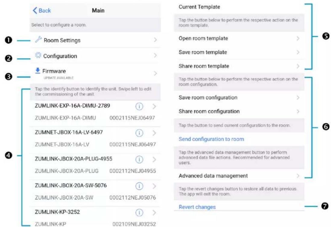
text_image
Back Main Select to configure a room. Room Settings > Configuration > Firmware UPDATE AVAILABLE > Tap the identify button to identify the unit. Swipe left to edit the commissioning of the unit. ZUMLINK-EXP-16A-DIMU-2789 ZUMLINK-EXP-16A-DIMU 0002115NEJ06497 ZUMNET-JBOX-16A-LV-6497 ZUMNET-JBOX-16A-LV 0002115NEJ06497 ZUMLINK-JBOX-20A-PLUG-4955 ZUMLINK-JBOX-20A-PLUG 0002112NEJ04955 ZUMLINK-JBOX-20A-SW-5076 ZUMLINK-JBOX-20A-SW 0002112NEJ05076 ZUMLINK-KP-3252 ZUMLINK-KP 002109NEJ03252 Current Template Tap the button below to perform the respective action on the room template. Open room template > Save room template > Share room template > Tap the button below to perform the respective action on the room configuration. Save room configuration > Share room configuration > Tap the button to send current configuration to the room. Send configuration to room Tap the advanced data management button to perform advanced data file actions. Recommended for advanced users. Advanced data management > Tap the revert changes button to restore all data to previous. The app will exit the room. Revert changes ① ② ③ ④ ⑤ ⑥ ⑦NOTE: The numbers below correspond with the numbers in the Main screen diagram.
-
Room Settings: Edit the Room Name, PIN, Floor ID, Zone ID, and Network information.
-
Configuration: Edit the room logic to view the current state of the room.
-
Occupancy Sensors: View details for the connected sensor(s) or edit the sensor name.
- Photo Sensors: View details for the connected sensor(s) or edit the sensor name.
- Load Controllers: Identify and view details for the connected load controller(s).
- ZUMLINK-JBOX-16A-LV and ZUMNET-JBOX-16A-LV load controllers:
■ View Current Scene, Daylighting status, and Output Level.
■ Override: The state of the load when Override is recalled. Click the toggle to turn the load on or off during Override.
- Assign the occupancy mode (Occupancy menu), vacancy mode (Vacancy menu), vicinity mode (Vicinity menu), and daylight harvesting (Photo menu) to specific load controllers.
■ View Dimming Values
■ Edit the Dimming Curve Configuration or Dimmer Scenes Configuration.
- ZUMLINK-JBOX-20A-PLUG load controller:
■ Override: The state of the load when Override is recalled. Click the toggle to turn the load on or off during Override.
- Assign the occupancy mode (Occupancy menu), vacancy mode (Vacancy menu), vicinity mode (Vicinity menu), and daylight harvesting (Photo menu) to specific load controllers.
- ZUMLINK-JBOX-20A-SW load controller:
■ Closed: Click the toggle to turn the load on or off.
■ Override: The state of the load when Override is recalled. Click the toggle to turn the load on or off during Override.
- Assign the occupancy mode (Occupancy menu), vacancy mode (Vacancy menu), vicinity mode (Vicinity menu), and daylight harvesting (Photo menu) to specific load controllers.
■ Scenes: Allow keypad access to the scene by selecting or deselecting the checkbox. Determine the state of the load when the scene is recalled by clicking the toggle on or off.
- ZUMLINK-EXP-16A-DIMU load controller:
■ View Current Scene, Daylighting status, and Output Level.
- Override: The state of the load when Override is recalled. Click the toggle to turn the load on or off during Override.
- Assign the occupancy mode (Occupancy menu), vacancy mode (Vacancy menu), vicinity mode (Vicinity menu), and daylight harvesting (Photo menu) to specific load controllers.
■ View Dimming Values.
■ Edit the Dimmer Scenes Configuration.
- Scenes: View and edit room scenes: Scene 1 - Scene 16. When editing the scene, tap the Identify icon to identify the load controller. The load controller emits a sound and flashes the Link LED. The connected loads also flash.
- Keypads: Identify and view details for the connected keypad(s). Edit the keypad name and assign the button layout.
° Adjust the Double Tap Speed: Set the amount of time between two button presses to qualify as a double tap.
- Specify the Button Layout and click on a button to configure button actions. Button action options:
■ None
■ Off: Assigned load controllers turn off.
■ On: Assigned loads turn on.
■ Raise: Assigned load controllers raise.
■ Toggle: Switches load controllers between ON and OFF states
■ Lower: Assigned load controllers lower.
■ Recall Scene 1 - Scene 16: Assigned load controllers recall the behavior set for the specified scene.
- Export to Hub: Name and send information to ZUM-HUB4 for macro actions.
- Load Shedding: Set the maximum levels for load shedding.
- Load/Sensor Groups: Create groups within the room.
- DALI Controllers: Address drivers, create DALI groups, assign drivers, and identify drivers.
- Current Scene: Displays the current room scene.
-
Occupancy Status: Displays occupied or vacant. If any area of the room is occupied, then the status is Occupied. When all areas of the room are vacant, the status is Vacant.
-
Firmware: To update firmware, refer to Update Firmware with the Züm App on page 164..
-
Discovered Room Devices: Identify a device and edit the commissioning settings

text_image
Tap the identify button to identify the unit. Swipe left to edit the commissioning of the unit. ZUMNET-JBOX-16A-LV-6497 ZUMNET-JBOX-16A-LV 0002115NEJ06497 ZUMLINK-JBOX-20A-PLUG-4955 ZUMLINK-JBOX-20A-PLUG 0002112NEJ04955 ZUMLINK-JBOX-20A-SW-5076 ZUMLINK-JBOX-20A-SW 0002112NEJ05076 ZUMLINK-KP-3252 ZUMLINK-KP 002109NEJ03252- Tap the Identify icon to identify a device. A load controller emits a sound and the Link LED flashes. The connected loads also flash. A keypad flashes its LED.
-
Tap the device to edit or review the device details: Edit Name. Review the Model, Serial Number, Status, and edit the device settings.
-
Current Template Settings: Choose Open room template, Save room template, or Share room template.
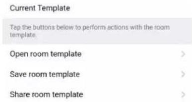
text_image
Current Template Tap the buttons below to perform actions with the room template. Open room template > Save room template > Share room template >6. Configuration Data:
- Save room configuration: Save the room configuration data in the space.
- Share room configuration: Share the room configuration data in the space.
- Send configuration to room: Send room logic changes made in the app to the room.
- Advanced data management: Review the Map, Logic, and Settings of the data currently loaded. Load, save or share new Map, Logic, or Settings data.
Tap the button below to perform the respective action on the room configuration.
Save room configuration
Share room configuration
Tap the button to send current configuration to the room.
Send configuration to room
Tap the advanced data management button to perform advanced data file actions. Recommended for advanced users.
Advanced data management
NOTE: Changes made in the app are not sent to the room until they are deployed using the Send configuration to room button.
- Revert changes: Restore all non-deployed changes made since launching the app.

text_image
Tap the revert changes button to restore all data to previous. The app will exit the room. Revert changes 2115NEJ06497-ZUMNET-...Sensor Test Mode
Use Sensor Test Mode to view a presence detector's status, and easily edit a presence detector's settings after they are installed. To access the Sensor Test Mode from the Züm app Main Screen, tap Configuration and tap Occupancy Sensors. A list of occupancy sensor components displays, including the occupancy sensor components for load controllers and presence detectors.
In this example, the occupancy sensor component for the presence detector is the ZUMLINK-US-ONEWAY-DLS-RLY-0074-2. The other occupancy sensors listed are for load controllers.

text_image
Back Occupancy Sensors Select a sensor below to see its details ZUMLINK-JBOX-16A-LV-0536-2 OccSensor 0002133NEJ10536 ZUMLINK-JBOX-20A-PLUG-2522-2 OccSensor 000X142522 ZUMLINK-US-ONEWAY-DLS-RLY-0074-2 OccSensor 21150MA00074 ZUMLINK-JBOX-20A-SW-3164-2 OccSensor 000X143164 ZUMNET-JBOX-16A-LV-6972-2 OccSensor 0002131NEJ06972 SENSOR TEST MODE 2131NEJ06972-ZUMNET-JBOX-16A...To enter test mode, tap Sensor Test Mode at the bottom of the screen. The same list of sensors displays. To exit test mode, tap Stop Test Mode.

text_image
Back Sensor-Test-Mode Toggle to Latch Motion Sensor Indicators. Latch Motion Sensor Indicators Tap the identify button to identify the unit. Swipe left to edit the commissioning of the unit. US IR ZUMLINK-JBOX-16A- LV-0536-2 Vacant > ZUMLINK-JBOX-20A- PLUG-2522-2 Vacant > ZUMLINK-US- ONEWAY-DLS-RLY- 0074-2 ○ ○ > ZUMLINK-JBOX-20A- SW-3164-2 Vacant > ZUMNET-JBOX-16A-LV- 6972-2 Occupied > Clear Motion Indicators STOP TEST MODE 2131NEJ06972-ZUMNET-JBOX-16A...Sensor Test Mode allows users to view real-time status and US and PIR sensor technology feedback. This screen enables users to make adjustments and confirm the expected detection sensitivities. For presence detectors, the radio button indicates whether the Ultrasonic or Infrared technology triggered. For non-system presence detectors, the room status is identified as Occupied or Vacant.
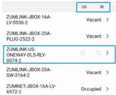
text_image
US IR ZUMLINK-JBOX-16A-LV-0536-2 Vacant > ZUMLINK-JBOX-20A-PLUG-2522-2 Vacant > ZUMLINK-US-ONEWAY-DLS-RLY-0074-2 ○ ○ > ZUMLINK-JBOX-20A-SW-3164-2 Vacant > ZUMNET-JBOX-16A-LV-6972-2 Occupied >Tap next to the presence detector to adjust the Name, Timeout, Range, and Sensitivity, as well as review the room Status and connected loads. Refer to Adjust Ultrasonic Sensitivity on page 226 for best practices on adjusting sensitivity.

text_image
Back OccSensor SN: 2115OMA00074; FW: v1.4984.15290 Name ZUMLINK-US-ONEWAY-DLS-RLY-0074-2 Tap to configure the number of seconds that must elapse before the sensor identifies room as occupied. Local Timeout (5-1800 sec) 300 Status Occupied Tap To Configure the sensor range and sensitivity Range(distance) 190 Sensitivity 7 This sensor is associated with the following load controller(s). ZUMLINK-JBOX-20A-SW-3164-1 ⓘ ZUMLINK-JBOX-20A-SW 000X143164 ZUMLINK-JBOX-16A-LV-0536-1 ⓘ ZUMLINK-JBOX-16A-LV 0002133NEJ105 36 ZUMNET-JBOX-16A-LV-6972-1 ⓘ 2131NEJ06972-ZUMNET-JBOX-16A...Adjust Ultrasonic Sensitivity
You can adjust the Ultrasonic (US) sensitivity in US and Dual Technology (DT) presence detectors. Passive Infrared (PIR) sensitivity is fixed and cannot be adjusted in PIR or DT presence detectors.
- Occupy the space where the US or DT presence detector is installed, and access Sensor Test Mode in the Züm app. Refer to Sensor Test Mode on page 223.
-
In the Züm app, locate the desired presence detector(s) in the list and tap Sensor Test Mode to begin the test.
-
Move around the room and observe the behavior of the US and IR radio buttons.
NOTE: The radio buttons light momentarily to identify the presence detector and technology triggered. Use the Latch Motion Sensor Indicators toggle to retain the radio button with the last motion detected. The Clear Motion Indicator button resets the radio buttons.
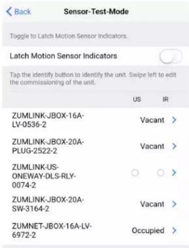
text_image
Back Sensor-Test-Mode Toggle to Latch Motion Sensor Indicators. Latch Motion Sensor Indicators Tap the identify button to identify the unit. Swipe left to edit the commissioning of the unit. US IR ZUMLINK-JBOX-16A- LV-0536-2 Vacant > ZUMLINK-JBOX-20A- PLUG-2522-2 Vacant > ZUMLINK-US- ONEWAY-DLS-RLY- 0074-2 ○ ○ > ZUMLINK-JBOX-20A- SW-3164-2 Vacant > ZUMNET-JBOX-16A-LV- 6972-2 Occupied >Clear Motion Indicators
STOP TEST MODE
2131NEJ06972-ZUMNET-JBOX-16A...
- If the presence detector does not trigger enough or triggers too much, press next to the presence detector to make adjustments to the sensitivity.

text_image
Back OccSensor SN: 21150MA00074; FW: v1.4984.15290 Name ZUMLINK-US-ONEWAY-DLS-RLY-0074-2 Tap to configure the number of seconds that must elapse before the sensor identifies room as occupied. Local Timeout (5-1800 sec) 300 Status Occupied Tap To Configure the sensor range and sensitivity Range(distance) 190 Sensitivity 7 This sensor is associated with the following load controller(s). ZUMLINK-JBOX-20A-SW-3164-1 ⓘ ZUMLINK-JBOX-20A-SW 000X143164 ZUMLINK-JBOX-16A-LV-0536-1 ⓘ ZUMLINK-JBOX-16A-LV 0002133NEJ105 36 ZUMNET-JBOX-16A-LV-6972-1 ⓘ 2131NEJ06972-ZUMNET-JBOX-16A...- Move the Sensitivity or Range slider to the desired position.
- To test the new setting, click to return to Sensor Test Mode.
- Repeat the process from step 3 until the desired sensitivity is attained.
Hub Web Interface
The ZUM-HUB4 is configured using the web interface. Connect to the device by entering the device hostname into a web browser. The hostname is comprised of "ZUM-HUB4-" followed by the entire MAC address (e.g., ZUM-HUB4-00107FCA1112)"ZUM-FL-" and the last 8 digits of the MAC address (e.g., ZUM-FL-7F8764BF). The New User Registration screen is displayed during the first connection. Enter the user's Username, Password, Firstname, Lastname, and Email Address, and then click Submit.

text_image
New User Registration Username Password Firstname Lastname Email Address SubmitWeb Interface Overview
The web interface gives users the ability to configure room behavior globally across the ZUM-HUB4, by Room Category, by Floor, and by Room.
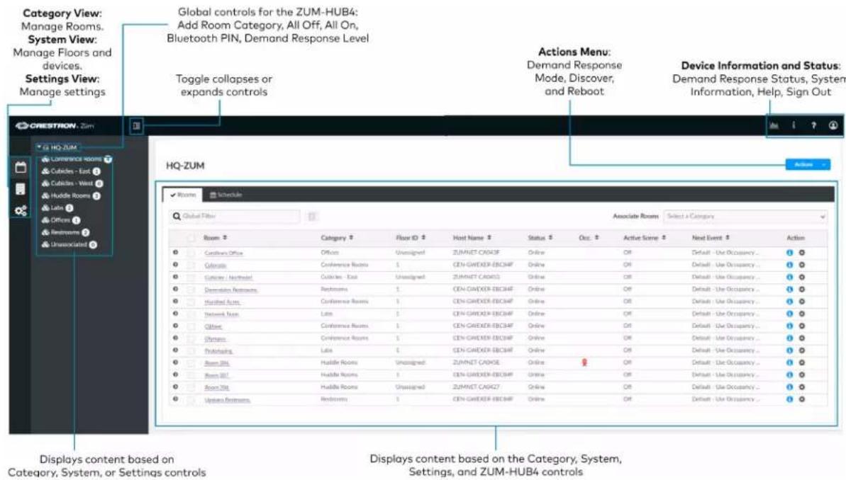
text_image
Category View: Manage Rooms. System View: Manage Floors and devices. Settings View: Manage settings Global controls for the ZUM-HUB4: Add Room Category, All Off, All On, Bluetooth PIN, Demand Response Level Toggle collapses or expands controls Actions Menu: Demand Response Mode, Discover, and Reboot Device Information and Status: Demand Response Status, System Information, Help, Sign Out HQ-ZUM HQ-ZUM Schedule Global Filter Associate Rooms Select a Category Room Category Floor ID Host Name Status Out Active Scene Next Event Action Customs Office Office Unsigned ZUMNET CAPX3F Online OR Default - Use Occupancy ... Cyclicals Conference Rooms 1 CEN-GWEXER-EBC3MF Online OR Default - Use Occupancy ... Cyclicals / Northeast Cyclicals - East Unsigned ZUMNET CAPX52 Online OR Default - Use Occupancy ... Demotion Retrosers Restrooms 1 CEN-GWEXER-EBC3MF Online OR Default - Use Occupancy ... Harvest Rooms Conference Rooms 1 CEN-GWEXER-EBC3MF Online OR Default - Use Occupancy ... Network Rooms Late 1 CEN-GWEXER-EBC3MF Online OR Default - Use Occupancy ... Other Conference Rooms 1 CEN-GWEXER-EBC3MF Online OR Default - Use Occupancy ... Systems Conference Rooms 1 CEN-GWEXER-EBC3MF Online OR Default - Use Occupancy ... Prototyping Late 1 CEN-GWEXER-EBC3MF Online OR Default - Use Occupancy ... Room Only Hualty Rooms Unsigned ZUMNET CAPX6E Online OR Default - Use Occupancy ... Room Only Hualty Rooms 1 CEN-GWEXER-EBC3MF Online OR Default - Use Occupancy ... Room Only Hualty Rooms Unsigned ZUMNET CAPX27 Online OR Default - Use Occupancy ... Systems Prototyping Restrooms 1 CEN-GWEXER-EBC3MF Online OR Default - Use Occupancy ... Displays content based on the Category, System, Settings, and ZUM-HUB4 controlsCategory View, System View, and Settings View
The web interface has three configuration sections: Category View to manage Rooms, System View to manage Floors and devices, and Settings View to manage settings.
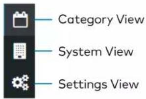
text_image
Category View System View Settings ViewCategory View
The Category View lists room categories and rooms (in the Rooms tab) that have been discovered by the ZUM-HUB4. Room Categories are intended to be groupings of all rooms that are a similar type (for example, office or conference rooms) to provide easy monitoring and control. Rooms that have not been assigned to a Room Category are kept in the Unassociated category. Select the Schedule tab to edit default behavior for Day Patterns, Room States and Holidays.
- Manage Rooms on page 246
-
Manage Room Categories
-
Set the Bluetooth PIN on page 239
- Configure the Demand Response Mode and Level on page 242
• Schedule Room Behavior on page 251
System View
The System View lists Floors and rooms (in the Rooms tab) that are discovered by the ZUM-HUB4. Use the Hardware Management tab to view and edit device information, such as assigning a device to a floor.
- Manage Floors on page 260
- Set the Bluetooth PIN for a Floor on page 241
- Set the Demand Response Level for a Floor on page 245
- Manage Devices on page 261
Settings View
The Settings View manages the settings for the ZUM-HUB4, Users, External Control, and Commissioning. The Settings tab is open by default.
- Manage Settings on page 265
- Manage Users on page 268
- Manage External Controls on page 270
- Manage Commissioning on page 274
Global Settings and Actions for the ZUM-HUB4
Apply settings that effect all devices discovered by the ZUM-HUB4 regardless of the room, room category, or floor the device is assigned.
ZUM-HUB4 actions:
- Configure Demand Response Mode on page 242
• Discover Rooms on page 234
• Reboot ZUM-HUB4 on page 279
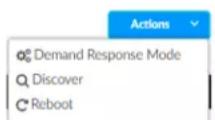
ZUM-HUB4 controls:
- Add a Room Category
- Turn On/Off All Discovered Devices on page 237
- Set the Bluetooth PIN for All Discovered Devices on page 239
- Set the Demand Response Level for All Discovered Devices on page 243
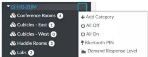
text_image
HQ-ZUM Conference Rooms 4 Cubicles - East 1 Cubicles - West 0 Huddle Rooms 3 Labs 2 + Add Category All Off All On Bluetooth PIN Demand Response LevelNavigation Toggle
Click to collapse or the Category View, System View, Setting Views, and the global ZUM-HUB4 settings.
Device Information and Status
View the Demand Response status, system alerts, help information, or sign out of the web interface. Refer to Review Device Information and Status on page 277.

text_image
Mobile app icons including profile, information, a question mark, and user profileWeb Interface Configuration
After using the Züm app to setup Züm spaces and logging into web interface, configure the ZUM-HUB4:
Related topics:
• Zūm App Configuration on page 158
• Hub Web Interface on page 229
Discover Rooms
To discover rooms:
- Click the Actions menu
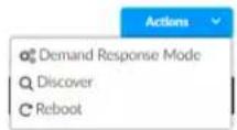
- Click Discover. The Discover window opens.
- Select the type of rooms you want to discover.
- Click Discover to Discover rooms or close the window.
During the discover process, a Stop button displays as an option to stop discovering.
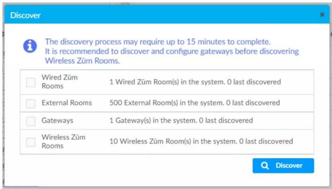
text_image
Discover The discovery process may require up to 15 minutes to complete. It is recommended to discover and configure gateways before discovering Wireless Zūm Rooms. Wired Zūm Rooms 1 Wired Zūm Room(s) in the system. 0 last discovered External Rooms 500 External Room(s) in the system. 0 last discovered Gateways 1 Gateway(s) in the system. 0 last discovered Wireless Zūm Rooms 10 Wireless Zūm Room(s) in the system. 0 last discoveredAdd a Room Category
To create a room category:
- Click the menu beside the ZUM-HUB4.

text_image
HQ-ZUM Conference Rooms 4 Cubicles - East 1 Cubicles - West 0 Huddle Rooms 3 Labs 2 Offices 1 Restrooms 2 Unassociated 0 Add Category All Off All On Bluetooth PIN Demand Response Level- Click Add Category.
- Type the name of the Room Category.
- Click to save the Room Category or to cancel.

text_image
Category View HQ-ZUM Front Office Conference Roams 4For more information about Room Categories, refer to Manage Room Categories.
Rename a Room Category
Room Category names can be renamed to provide a clear description of the connected rooms. To rename the Room Category name:
- Click the menu beside the Room Category name.
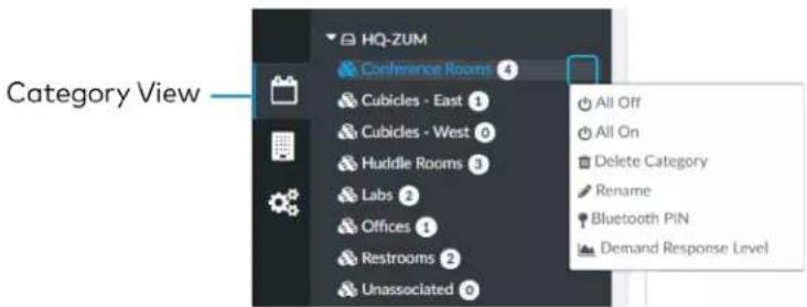
text_image
HQ-ZUM Conference Rooms 4 Cubicles - East 1 Cubicles - West 0 Huddle Rooms 3 Labs 2 Offices 1 Restrooms 2 Unassociated 0 Category View All Off All On Delete Category Rename Bluetooth PIN Demand Response Level- Click Rename.
- Click to save the Room Category or to cancel.
For more information about Room Categories, refer to Manage Room Categories.
Turn Rooms On or Off
Control a room by turning on/off the all rooms, all rooms in a Room Category, all rooms on a Floor, or by choosing a lighting scene for a specific room.
This section provides the following information:
• Turn On/Off All Discovered Devices on page 237
• Turn On/Off a Room Category on page 237
• Turn On/Off a Floor on page 238
• Turn On/Off a Room on page 238
Turn On/Off All Discovered Devices
To turn all devices on/off:
- Open the Category View.
- Click the menu beside the ZUM-HUB4.
- Click All Off or All On.

text_image
Category View HQ-ZUM Conference Rooms 4 Cubicles - East 1 Cubicles - West 0 Huddle Rooms 3 Labs 2 Offices 1 Restrooms 2 Unassociated 0 + Add Category All Off All On Bluetooth PIN Demand Response LevelTurn On/Off a Room Category
To turn all devices on/off in a Room Category:
- Open the Category View.
- Click the menu beside the Room Category name.
- Click All Off or All On.

text_image
HQ-ZUM Conference Rooms 4 Cubicles - East 1 Cubicles - West 0 Huddle Rooms 3 Labs 2 Offices 1 Restrooms 2 Unassociated 9 Category View All Off All On Delete Category Rename Bluetooth PIN Demand Response LevelTurn On/Off a Floor
To turn all devices on/off on a Floor:
- Open the System View
- Click the menu beside the Floor name.
- Click All Off or All On.

text_image
HQ-ZUM Unassigned Floor All Off All On Bluetooth PIN Demand Response Level System ViewTurn On/Off a Room
You can turn a specific room on/off using the Control Room window, but this option provides more detailed settings. Refer to Control a Room on page 249.
Set the Bluetooth PIN
The Bluetooth PIN enables a mobile device with the Zūm app to connect to the Zūm Wired Keypad or the Zūm Network Bridge. The Bluetooth PIN can be set for all discovered devices, all devices in a Room Category, all devices on a Floor, or all devices in a Room.
NOTES:
- Once a Bluetooth PIN is set for a device, it remains until manually changed. For example, if a device moves to a different room or floor, the Bluetooth PIN does not automatically inherit the PIN set for the new location. The device keeps the PIN previously set.
- For Primary load controllers running firmware 3.6.18 and higher, the default PIN is 246800. For firmware lower than 3.6.18, the default PIN is 2468.
This section provides the following information:
- Set the Bluetooth PIN for All Discovered Devices on page 239
- Set the Bluetooth PIN for a Room Category on page 239
- Set the Bluetooth PIN for a Room on page 240
- Set the Bluetooth PIN for a Floor on page 241
Set the Bluetooth PIN for All Discovered Devices
To set the Bluetooth PIN for all devices:
- Open the Category View.
- Click the menu beside the ZUM-HUB4.
- Click Bluetooth PIN.
- Set the PIN (O to 9999).

text_image
Category View HQ-ZUM 1234 Cubicles - East- Click to save or to cancel.
Set the Bluetooth PIN for a Room Category
To set the Bluetooth PIN for devices in a Room Category:
- Open the Category View.
- Click the menu beside the Room Category name.
-
Click Bluetooth PIN.
-
Set the PIN (0 to 9999).

text_image
Category View HQ-ZUM 1234 Cubicles - East- Click to save or to cancel.
Set the Bluetooth PIN for a Room
To set the Bluetooth PIN for devices in a Room:
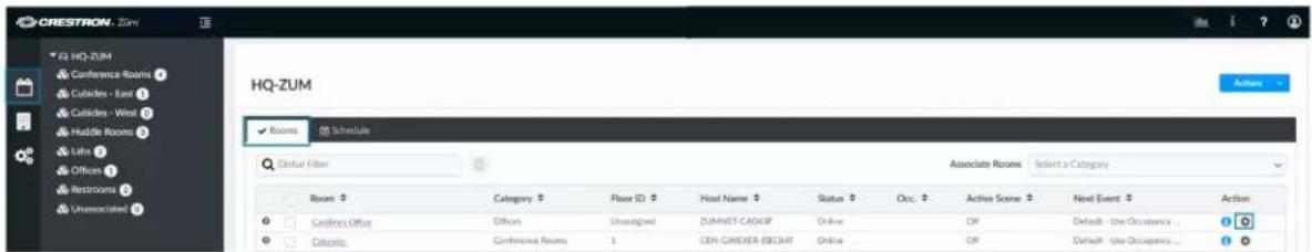
text_image
CRESTRON - Zum Ta HQ-ZUM Conference Rooms 1 Cubicles - East 2 Cubicles - West 3 Huddle Rooms 4 Lith 5 Officers 6 Restrooms 7 Unassisted 8 HQ-ZUM Rooms Schedule Global Filter Associate Rooms Select a Category Room Category Floor ID Host Name Status Occ. Active Scene Next Event Action Confine Office Offices Unassigned ZUMNET-CADMF Online Off Default - Use Occupancy... Controls Conference Rooms 1 CDN-CHELEX-EBCMF Online Off Default - Use Occupancy...-
Open the Category View and the Room tab.
-
Click the to open the Control Room window.
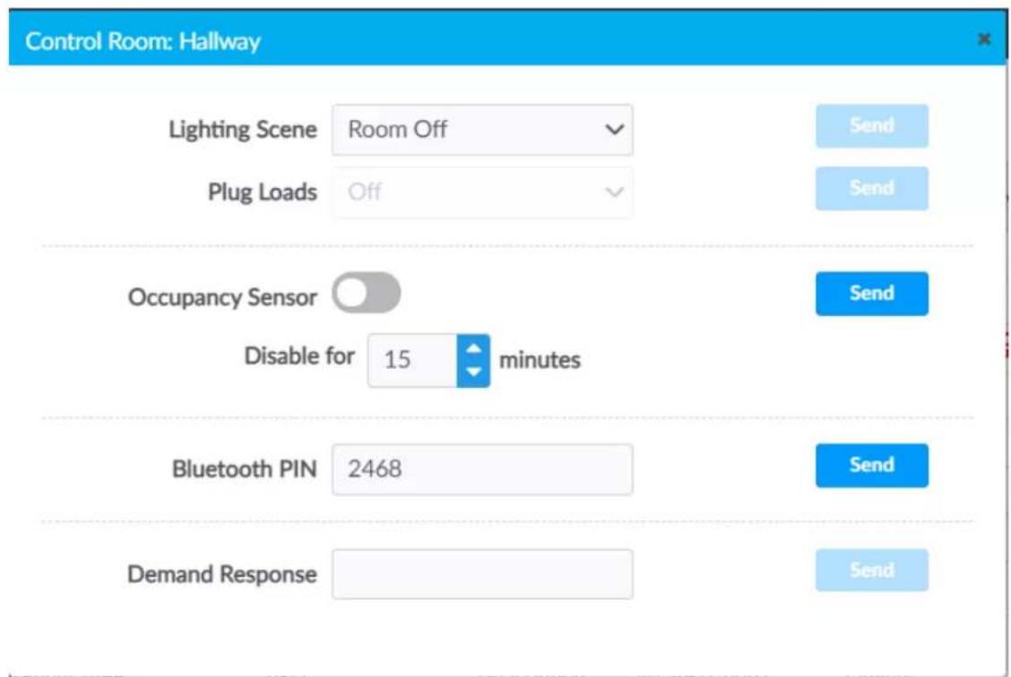
text_image
Control Room: Hallway Lighting Scene Room Off Plug Loads Off Occupancy Sensor Disable for 15 minutes Bluetooth PIN 2468 Demand Response Send Send Send Send- For Bluetooth PIN, set the PIN (0 to 9999).
- Click Send to send changes to the room, or close the Control Room window to discard unsaved changes.
Set the Bluetooth PIN for a Floor To set the Bluetooth PIN for devices on a floor:
- Open the System View.
- Click the menu beside the Floor name.
- Click Bluetooth PIN.
- Set the PIN (O to 9999).
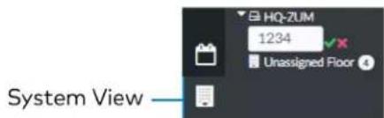
text_image
HQ-ZUM 1234 Unassigned Floor System View- Click to save or to cancel.
Configure the Demand Response Mode and Level
The Demand Response Level is used in emergency situations to override the current load settings in the room. The load levels reduce when a demand response command is received from the utility company. Demand Response Mode can be manually controlled by accessing the Actions Menu. Demand Response Levels can be set for all discovered devices, all devices in a Room Category, all devices on a Floor, or all devices in a Room.
NOTE: Once a Demand Response Level is set for a device, it remains until manually changed. For example, if a device moves to a different room or floor, the Demand Respond Level does not automatically inherit the level set for the new location. The device keeps the level previously set.
This section provides the following information:
- Configure Demand Response Mode on page 242
- Set the Demand Response Level for All Discovered Devices on page 243
- Set the Demand Response Level for a Room Category on page 243
- Set the Demand Response Level for a Room on page 244
- Set the Demand Response Level for a Floor on page 245
Configure Demand Response Mode
To manually turn Demand Response Mode on or off:
- Click the Actions menu.
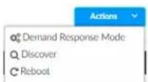
- Click Demand Response Mode. The Configure Demand Response Mode window opens.
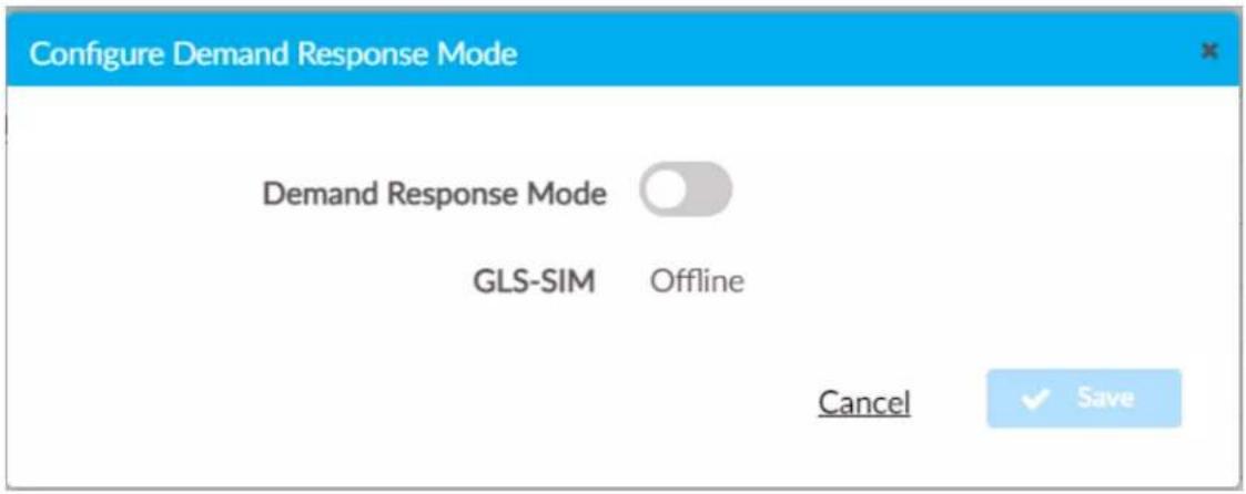
text_image
Configure Demand Response Mode Demand Response Mode GLS-SIM Offline Cancel ✓ Save- Click the toggle turn Demand Response Mode on or off.
If a GLS-SIM has been discovered by the ZUM-HUB4, the GLS-SIM status is represented as Offline or Online.
- Click Save to save the settings or Cancel to close the window without saving.
Set the Demand Response Level for All Discovered Devices To set the Demand Response Level for all devices:
- Open the Category View.
- Click the menu beside the ZUM-HUB4.
- Click Demand Response Level.
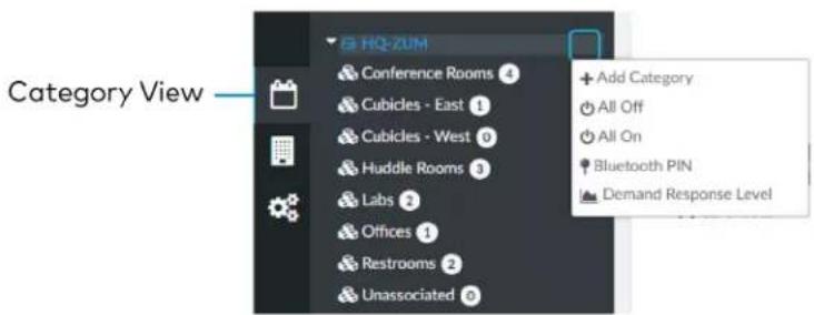
text_image
Category View HQ-ZUM Conference Rooms 4 Cubicles - East 1 Cubicles - West 0 Huddle Rooms 3 Labs 2 Offices 1 Restrooms 2 Unassociated 5 Add Category All Off All On Bluetooth PIN Demand Response Level- Set the light level (0 to 100).

text_image
Category View HQ-ZUM 10q Cubicles - East- Click to save or to cancel.
Set the Demand Response Level for a Room Category To set the Demand Response Level for devices in a Room Category:
- Open the Category View.
- Click the menu beside the Room Category name.
- Click Demand Response Level.

text_image
HQ-ZUM Conference Rooms 4 Cubicles - East 1 Cubicles - West 0 Huddle Rooms 3 Labs 2 Offices 1 Restrooms 2 Unassociated 0 Category View All Off All On Delete Category Rename Bluetooth PIN Demand Response Level- Set the light level (0 to 100).

text_image
Category View HQ-ZUM 100 Cubicles - East- Click to save or to cancel.
Set the Demand Response Level for a Room To set the Demand Response Level for devices in a Room:

text_image
CRESTRON - Zum HQ-ZUM Conference Rooms 1 Cubicles - East 1 Cubicles - West 1 Huddle Rooms 1 Ltrs 1 Offices 1 Restrooms 1 Unassociated 1 HQ-ZUM Rooms Schedule Global Filter Room Category Floor ID Host Name Status Occ Active Scene Next Event Action Cubicles Office Offices Undeveloped ZUMNET-CAD3/F Online Off Default - Use Occupancy ... Colorator Conference Rooms CEN-GWEXER-ECB34F Online Off Default - Use Occupancy ...- Open the Category View and the Room tab.
- Click the to open the Control Room window.

text_image
Control Room: Hallway Lighting Scene Room Off Plug Loads Off Occupancy Sensor Disable for 15 minutes Bluetooth PIN 2468 Demand Response Send Send Send Send- For Demand Response, set the level (0 to 100).
- Click Send to send changes to the room, or close the Control Room window to discard unsaved changes.
Set the Demand Response Level for a Floor To set the Demand Response Level for devices on a Floor:
- Open the System View.
- Click the menu beside the Floor name.
- Click Demand Response Level.
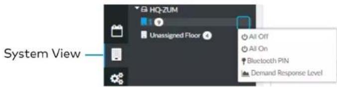
text_image
System View HQ-ZUM Unassigned Floor All Off All On Bluetooth PIN Demand Response Level- Set the light level (0 to 100).

text_image
HQ-ZUM 100 Unassigned Floor System View- Click to save or to cancel.
Manage Rooms
The Rooms tabs lists the Rooms discovered by the ZUM-HUB4 or the rooms assigned to a selected Room Category. Use the Rooms tab search for a room, delete rooms, reassign room categories, edit a room name, view room details, or control a room. Access the Rooms tab through either the Category View or the System View tabs.

text_image
Category View System View Settings ViewRooms must be discovered by the ZUM-HUB4 before performing any procedure in this section. Refer to Discover Rooms on page 234.
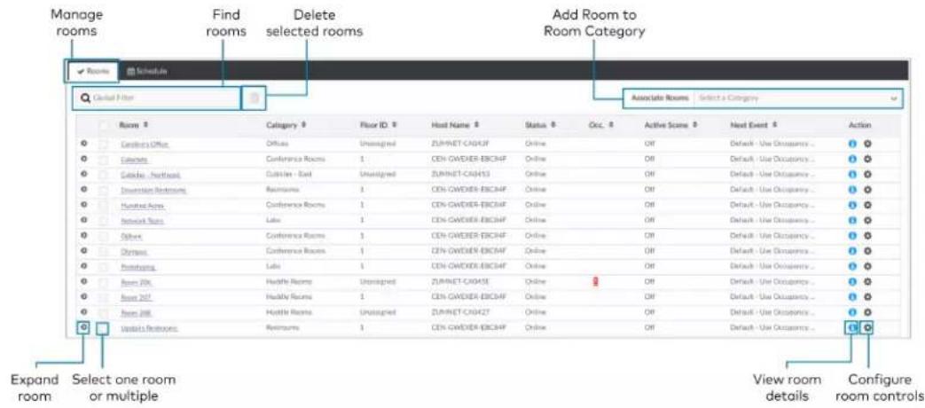
text_image
Manage rooms Find rooms Delete selected rooms Add Room to Room Category Schedule Place 1 Filter Room Category: Office Officer Unassigned ZUMNET-CHO43F Online Off Default - Use Occupancy... C Culums Conference Rooms 1 CEN-GWEDER-BCCHF Online Off Default - Use Occupancy... C Culums - Northeast Cutsler - East Unassigned ZUMNET-CHO453 Online Off Default - Use Occupancy... C Culums - Northwest Restrooms 1 CEN-GWEDER-BCCHF Online Off Default - Use Occupancy... C Culums - Northeast Area Conference Rooms 1 CEN-GWEDER-BCCHF Online Off Default - Use Occupancy... C Culums - Network Area Late 1 CEN-GWEDER-BCCHF Online Off Default - Use Occupancy... C Culums - South Conference Rooms 1 CEN-GWEDER-BCCHF Online Off Default - Use Occupancy... C Culums - Ophora Conference Rooms 1 CEN-GWEDER-BCCHF Online Off Default - Use Occupancy... C Culums - Prototyping Late 1 CEN-GWEDER-BCCHF Online Off Default - Use Occupancy... C Culums - Room 206 Hostile Rooms Unassigned ZUMNET-CHO45E Online Off Default - Use Occupancy... C Culums - Room 207 Hostile Rooms Unassigned CEN-GWEDER-BCCHF Online Off Default - Use Occupancy... C Culums - Room 208 Hostile Rooms Unassigned ZUMNET-CHO427 Online Off Default - Use Occupancy... C Culums - Restrooms Restrooms 1 CEN-GWEDER-BCCHF Online Off Default - Use Occupancy... CReview Rooms
The Room list displays room information including built-in components.
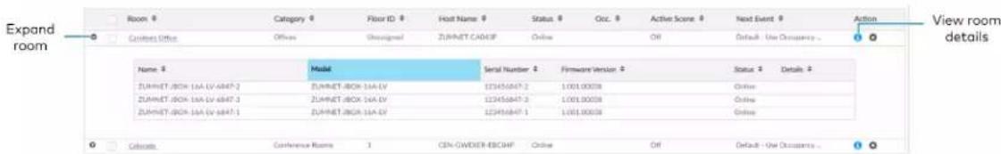
text_image
Expand room Room # Category # Floor ID # Host Name # Status # Occ. # Active Score # Next Event # Action View room details Citation Office Officer Unassigned ZUMNET-BOX-1A LV Online Off Default - Use Occupancy - Name # Model Serial Number # Firmware Version # Status # Details + ZUMNET-BOX 1A LV 123456847 2 1.001.00038 Online ZUMNET-BOX 1A LV 6847 3 123456847 2 1.001.00038 Online ZUMNET-BOX 1A LV 6847 1 123456847 1 1.001.00038 Online Collected: Conference Rooms 1 CEN-CWEDER-BOX-HP Online Off Default - Use Occupancy - 1• Room: Displays the room name
• Category: Displays the Room Category
• Floor ID: Displays the Floor ID. The Floor ID can be set in the Hardware Management tab of the Systems View. A Floor ID cannot be assigned to an External Room.
- Host Name: Displays the Host Name of room's main device.
- Status: Displays the room status Online of Offline.
- Occ: Identifies a room with an Occupancy Sensor. The Occupancy sensor symbols ( ) displays when occupancy is detected.
• Active Scene: Displays the current Scene. -
Next Event: Displays the upcoming event.
• Information ⓘ: Displays room details. -
Hostname: Displays the Hostname.
Room Type: Wired, Wireless, or External room
° ID: Displays the IP ID for a Wired room, the RF ID for a Wireless room, and the Module ID for an External room - Mirror Module: Indicates whether the room is associated with a Mirror Room
Occupancy Sensor State: Displays if the Occupancy Sensor is Enabled or Disabled - Plug Load State: Displays if the Plug Load is ON or OFF
- Last Scene Changed: Displays the date and time of the last Scene change.
- Last Online Status Changed: Displays the date and time of the last Online Status change
- Last Occupancy Status Changed: Displays the date and time of the last Occupancy Status change
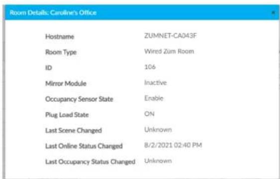
text_image
Room Details: Caroline's Office Hostname ZUMNET-CA043F Room Type Wired Zum Room ID 106 Mirror Module Inactive Occupancy Sensor State Enable Plug Load State ON Last Scene Changed Unknown Last Online Status Changed 8/2/2021 02:40 PM Last Occupancy Status Changed UnknownClick to expand the room to display information regarding the components. The Name, Model, Serial Number, Firmware Version, and Status of the devices are defined.
| Name | Model | Settle Number | Forward Version | Date | Details |
| 2014/PAI, BEOV 164-01/2023 | 2.941,PAI, BEOV 244-10 | TS2028-0252-1 | 1.001.00030 | Date | |
| 2014/PAI, BEOV 164-02/2023 | 2.941,PAI, BEOV 244-10 | TS2028-0252-1 | 1.001.00030 | Date | |
| 2014/PAI, BEOV 164-03/2023 | 2.941,PAI, BEOV 244-10 | TS2028-0252-1 | 1.001.00030 | Date | |
| 2014/PAI, BEOV 164-04/2023 | 2.941,PAI, BEOV 244-10 | TS2028-0252-1 | 1.001.00030 | Date | |
| 2014/PAI, BEOV 164-05/2023 | 2.941,PAI, BEOV 244-10 | TS2028-0252-1 | 1.001.00030 | Date | |
| 2014/PAI, BEOV 164-06/2023 | 2.941,PAI, BEOV 244-10 | TS2028-0252-1 | 1.001.00030 | Date | |
| 2014/PAI, BEOV 164-07/2023 | 2.941,PAI, BEOV 244-10 | TS2028-0252-1 | 1.001.00030 | Date | |
| 2014/PAI, BEOV 164-08/2023 | 2.941,PAI, BEOV 244-10 | TS2028-0252-1 | 1.001.00030 | Date | |
| 2014/PAI, BEOV 164-09/2023 | 2.941,PAI, BEOV 244-10 | TS2028-0252-1 | 1.001.00030 | Date |
Find a Room on the ZUM-HUB4
For a ZUM-HUB4 that has a large number of rooms, use the search feature to find a room name. To search for a room:
-
Click on the ZUM-HUB4 or on a Room Category.
-
Type in the Global Filter search bar. The filter populates results matching content in any of the table fields (Room, Category, Floor ID, Host Name, Status, Occ., Active Scene, or Next Event).

text_image
Find rooms Rooms Schedule Global Filter Room Category- Click the desired room name.
Add a Room to a Room Category
To move a room to a different Room Category:
-
Click on the ZUM-HUB4 or on a Room Category.
-
Select the desired room or rooms.
-
Click the Associate Rooms menu.
-
Select the desired Room Category.
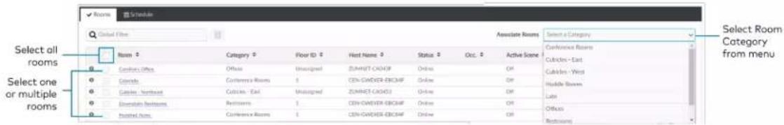
text_image
Select all rooms Select one or multiple rooms Select Room Category from menu ✓ Rooms ✓ Schedule Global Filter Associate Rooms Select a Category Room Category Floor ID Host Name Status Occ Active Scene Confucien Rooms Confucien Office Unassigned ZUMNET CASHF Online Off Alternate Conference Rooms CEN-GAWDER-BOXMF Online Off Cabinet - East Unassigned ZUMNET CASHF Online Off Cabinet - West Unassigned ZUMNET CASHF Online Off Cabinet - Northeast Unassigned ZUMNET CASHF Online Off Cabinet - East Intermediate Retirems Restriums CEN-GAWDER-BOXMF Online Off Cabinet - West Intermediate Retirems Restriums CEN-GAWDER-BOXMF Online Off Cabinet - East Intermediate Retirems Restriums Restriums Restriums- A confirmation dialog opens. Click Yes to add the room(s) the Room Category or No to cancel.
Delete a Room
To delete a room:
-
Click on the ZUM-HUB4 or on a Room Category.
-
Select the desired room or rooms.
-
Click to delete the room.
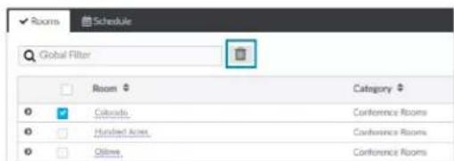
text_image
Rooms Schedule Global Filter Room Category Colours Conference Rooms Hundred Acres Conference Rooms Online Conference Rooms- A confirmation dialog opens. Click Yes to add the room(s) the Room Category or No to cancel.
Control a Room
Open the Control Room window to select a Lighting Scene, change the state of Plug Loads, enable or disable the occupancy sensor, set the Bluetooth PIN, or set the Demand Response level for a specific room.
-
Click on the ZUM-HUB4 or on a Room Category.
-
For the desired room, click the to open the Control Room options.

text_image
Control Room: Hallway Lighting Scene Room Off Plug Loads Off Occupancy Sensor Disable for 15 minutes Bluetooth PIN 2468 Demand Response Send Send Send SendLighting Scene
To select the Lighting Scene set in the Room:
-
Select a Lighting Scene from the drop down menu.
-
Click Send to send changes to the room, or close the Control Room to discard unsaved changes.
Plug Loads
This setting is only active for rooms with a Plug Load Controller.
-
Select On or Off from menu to turn the load on or off.
-
Click Send to send changes to the room, or close the Control Room to discard unsaved changes.
Occupancy Sensor
To enable or temporarily disable occupancy sensing:
-
Click the toggle to enable or temporarily disable occupancy sensing.
When disabling occupancy sensing, set the amount of time the occupancy sensor is disabled. The sensor may be disabled for up to 1,415 minutes or appropriately 23 hours. -
Click Send to send changes to the room, or close the Control Room to discard unsaved changes.
Bluetooth PIN
Set the Bluetooth PIN for Bluetooth devices in a room.
- Set the PIN (0 to 9999)
- Click Send to send changes to the room, or close the Control Room to discard unsaved changes.
Refer to Set the Bluetooth PIN on page 239 for more information.
Demand Response Level
Set the Demand Response Level for devices in a room.
- Set the level (0 to 100).
- Click Send to send changes to the room, or close the Control Room to discard unsaved changes.
Refer to Configure the Demand Response Mode and Level on page 242 for more information.
Schedule Room Behavior
The Schedule tab displays and allows you to edit the device calendar, Day Patterns, Room States, Holidays, and the astronomical clock. The calendar displays a color-coded month view that identifies the Day Pattern that is assigned for each day of the month. The calendar is used to view and change which Day Pattern is set on a given day.
By default, weekdays are assigned the Workday Day Pattern and weekends are assigned the Weekend Day Pattern. Holidays that are enabled in Holidays on page 258 are added to the calendar automatically. Refer to the Day Pattern legend to match the color with the associated Day Pattern. To assign a Day Pattern:
- Open the Category View.

text_image
Category View System View Settings View-
Click the Schedule tab.
-
Click the desired date in the calendar. If necessary, change the month and year using the drop-down menus, and then click the desired date.
A menu displays a list of the available Day Patterns.
- Select the desired Day Pattern.
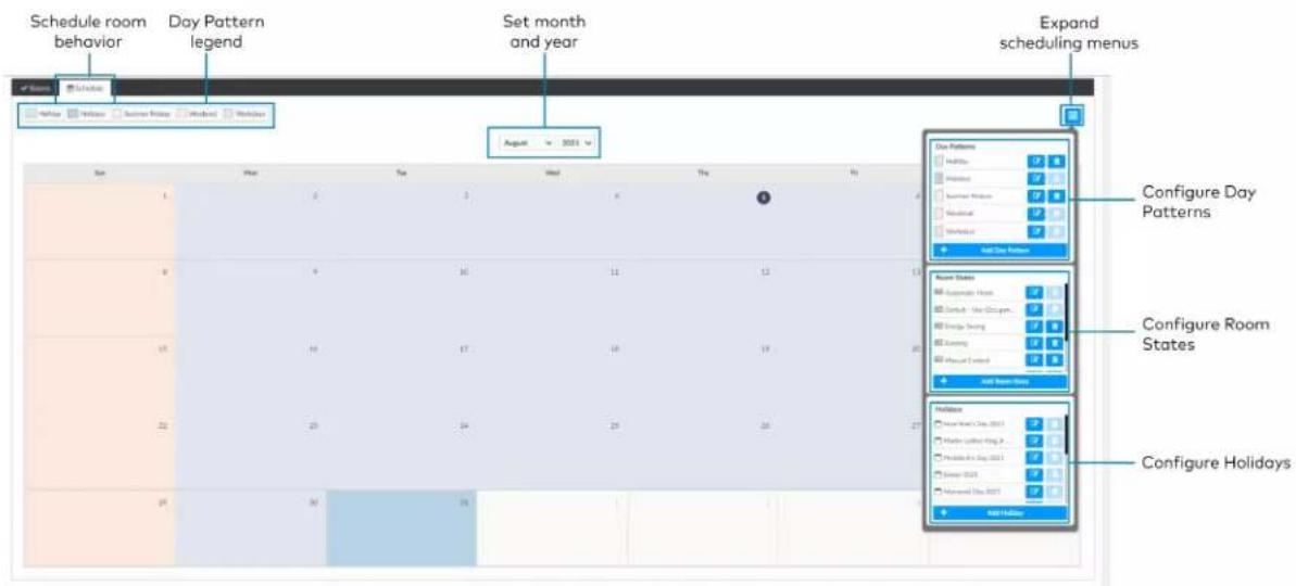
text_image
Schedule room behavior Day Pattern legend Set month and year Expand scheduling menus August 2021 Sun Day Tue Wed Thu Fri Day Patterns Add Day Settings Configure Day Patterns Add Day Settings Configure Room States Add Room Status Configure Room States Add Room Status Configure Holidays Add HolidayDay Patterns
A Day Pattern consists of various Room States that are assigned throughout the day. Each category can be assigned a different schedule of room states in a given day pattern. To access the Day Patterns menu, click the Schedule tab and click to expand the scheduling menus.

flowchart
graph TD
    A["Expand scheduling menus"] --> B["Day Patterns menu"]
    B --> C["Add Day Pattern"]
    C --> D["Holiday"]
    C --> E["Holidays"]
    C --> F["Summer Fridays"]
    C --> G["Weekend"]
    C --> H["Workdays"]
Add Day Patterns
Click Add Day Pattern and enter the desired Day Pattern name. Click to save the name, click to cancel.
Delete Day Pattern
To delete a Day Pattern:
- Click to delete a Day Pattern. A Confirmation window opens.
- Click Yes to delete the Day Pattern, or click No to keep the Day Pattern.
NOTE: A Default Day Pattern (such as Holidays, Weekend, and Workdays) cannot be deleted.
Configure Day Patterns
After adding a Day Pattern, the Add Day Pattern window opens. Alternatively, clicking beside a Day Pattern opens the Edit Day Pattern window. These windows display two menus: Room State Schedule and Sunrise/Sunset Schedule. The Room State Schedule opens by default.
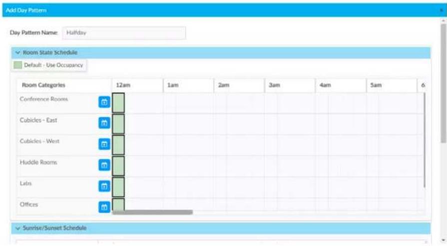
text_image
Add Day Pattern Day Pattern Name: Halfday ✓ Room State Schedule Default - Use Occupancy Room Categories 12am 1am 2am 3am 4am 5am 6 Conference Rooms Cubicles - East Cubicles - West Huddle Rooms Luts Offices ✓ Sunrise/Sunset ScheduleRoom State Schedule
Use the Room State Schedule window to modify the pattern of Room States in each Category for the selected Day Pattern.
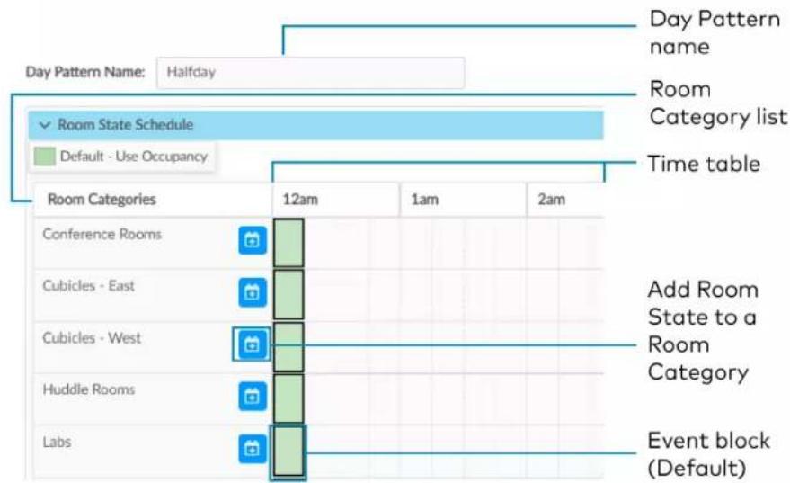
text_image
Day Pattern Name: Halfday Room Category list ✓ Room State Schedule Default - Use Occupancy Time table Room Categories 12am 1am 2am Add Room State to a Room Category Conference Rooms Cubicles - East Cubicles - West Huddle Rooms Labs Event block (Default)To add a Room State to a Room Category:
-
Click to add a Room State. The Add Room State window opens.
-
Select the desired Room State from the Name drop-down menu. The default Room State selections are examples of possible Room State applications and can be edited as needed.
• Automatic Mode
- Default - Use Occupancy
- Energy Saving
- Manual Control
- Morning Turn Off
- Morning Turn On
- Sweep Off
-
Select the desired Room State start time from the Time drop-down menu: 12 AM - 11:45 PM.
-
Click Ok to save the room state or Cancel to close the window without saving.
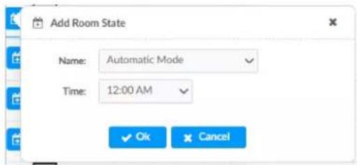
text_image
Add Room State Name: Automatic Mode Time: 12:00 AM OK CancelTo edit a default or custom event block:
- Change the assigned Room State:
- Click an event block, and a dialog opens.
- Click and choose a new Room State from the drop-down menu.
- Click Ok to save the changes or Cancel to close the window without saving.
- Change the assigned time:
Click and drag the event block to the desired time within the time table.
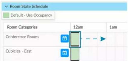
text_image
Room State Schedule Default - Use Occupancy Room Categories 12am 1am Conference Rooms Cubicles - EastClick and drag the event block to the desired time along the time table.
Sunrise/Sunset Schedule
The ZUM-HUB4 determines sunrise and sunset based on the location set in Location on page 266 settings. The Sunrise/Sunset Schedule assigns a Room State to a Room Category based on the Day Pattern and the sunrise or sunset. Only one Sunrise event and one Sunset event can be set for a Room Category per day. To assign Room States based on the sunrise or sunset:
- Expand the Sunrise/Sunset Schedule menu.
- Locate the Room Category.
-
Adjust the settings in the Sunrise events column and/or the Sunset events column.
-
ENABLE: Click the ENABLE toggle to allow sunrise or sunset to trigger an event.
- ROOM STATE: Select the a Room State from the drop-down menu.
- OFFSET (MIN): If necessary, set an offset duration in minutes. The offset can be positive so the Room State occurs after sunrise or sunset or negative so that the Room State occurs before sunrise or sunset.
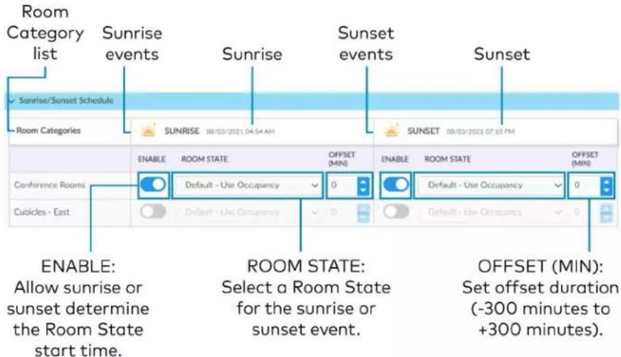
text_image
Room Category list Sunrise events Sunrise Sunset events Sunset Sunrise/Sunset Schedule Room Categories SUNRISE 08/02/2021 04:54 AM SUNSET 08/02/2021 07:30 PM ENABLE ROOM STATE OFFSET (MIN) Enable ROOM STATE OFFSET (MIN) Conference Rooms Default - Use Occupancy Default - Use Occupancy Default - Use Occupancy Default - Use Occupancy Default - Use Occupancy Default - Use Occupancy Default - Use Occupancy Default - Use Occupancy Default - Use Occupancy Default - Use Occupancy Default - Use Occupancy Default - Use Occupancy Default - Use Occupancy Default - Use Occupancy Default - Use Occupancy Default - Use Occupancy Default - Use Occupancy Default - Use Occupancy Default - Use Occupancy Default - Use Occupancy Default - Use Occupance Default - Use Occupancy Default - Use Occupancy Default - Use Occupancy Default - Use Occupancy Default - Use Occupancy Default - Use Occupancy Default - Use Occupancy Default - Use Occupancy Default - Use Occupancy Default - Use Occupancy Default - Use Occupancy Default - Use Occupancy Default - Use Occupancy Default - Use Occupancy Default - Use Occupancy Default - Use Occupancy Default - Use Occupancy Default - Use Occupancy Default - Use Occupancy Default - Use Occupancu ENABLE: Allow sunrise or sunset determine the Room State start time. ROOM STATE: Select a Room State for the sunrise or sunset event. OFFSET (MIN): Set offset duration (-300 minutes to +300 minutes).Room States
A Room State is both a set of events as well as a set of behaviors for a Room Category. It identifies the lighting scene that is recalled, the functionality of the occupancy sensor and the plug load controllers. To access the Room States menu, click the Schedule tab and click to expand the scheduling menus.
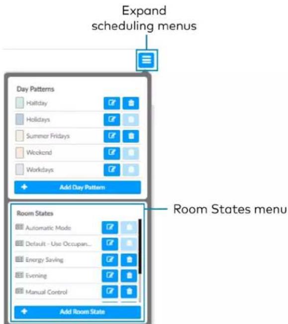
text_image
Expand scheduling menus Day Patterns Hallday Holidays Summer Fridays Weekend Workdays Add Day Pattern Room States menu Room States Automatic Mode Default - Use Occupant... Energy Saving Evening Manual Control Add Room StateConfigure a Room State
Click Add Room State to add a new Room state or to edit an existing Room State. The Room State Settings window opens. To configure a Room State in the Room State Settings window:
-
Enter or edit the name of the desired Room State in the Room State Name filed.
-
Configure the Properties:
-
Scene: Select Scene 1 - 16, None, or Room Off.
- Occupancy: Select Enabled to allow occupancy sensing, Disabled to turn occupancy sensing off, or Unaffected to use the setting of the previous event.
-
Plug Loads: Select On to turn on the Plug loads, Off to turn off the Plug Loads, or Unaffected to use the setting of the previous event.
-
Click Cancel to close the window without saving, or Add to add the Room State.

text_image
Room State Settings Room State Name Properties Scene Scene 1 Occupancy Enabled Plug Loads On Cancel + AddDelete a Room State
To delete a Room State:
- Click to delete a Room State. A confirmation window opens.
- Click Yes to delete the Room State, or click No to keep the Day Pattern.
NOTE: A Default Room State (such as Automatic Mode and Default - Use Occupancy) cannot be deleted.
Holidays
The Holidays menu allows you to create a new holiday and to edit the holiday properties. Holidays that are enabled are automatically added to the calendar in the Schedule tab. To access the Holidays menu, click the Schedule tab and click to expand the scheduling menus.

text_image
Expand scheduling menus Day Patterns Halfday Holidays Summer Fridays Weekend Workdays Add Day Pattern Room States Automatic Mode Default - Use Occupant... Energy Saving Evening Manual Control Add Room State Holidays Easter 2021 Memorial Day 2021 Independence Day 20... Appreciation Day Labor Day 2021 Add Holiday Holidays menuAdd Holidays
Click Add Holiday and type the desired Holiday name. Click to save the name, click to cancel.
Delete a Holiday
To delete a Holiday:
- Click to delete a Holiday. A confirmation window opens.
- Click Yes to delete the Holiday, or click No to keep the Holiday.
NOTE: A default Holiday cannot be deleted.
Configure Holidays
After adding a Holiday, the Holiday Settings window opens. Alternatively, clicking beside a Holiday opens the Edit Holiday Settings window. These windows display the Holiday settings. To configure Holidays in the Holiday Settings window:
- Enter or edit the name of the desired Holiday in the Holiday field.
-
Configure the Properties:
-
Day Pattern: By default, the Holiday Day Pattern is selected
- Enabled: By default, the Enabled toggle is on. Turn the toggle off to prevent the holiday from appearing in the calendar on the Schedule tab. When the toggle is off, the default Day Pattern is applied instead.
-
Observed: Select a date to observe the holiday.
-
Click Add to add the Holiday or Cancel to close the window.
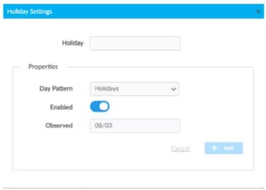
text_image
Holiday Settings Holiday Properties Day Pattern Holidays Enabled Observed 08/03 Cancel AddManage Floors
Rooms must be discovered by the ZUM-HUB4 before performing any procedure in this section. Refer to Discover Rooms on page 234. Access Floors in the System View. To manage a Floor, refer to the following information:
• Turn On/Off a Floor on page 238
- Set the Bluetooth PIN for a Floor on page 241
- Set the Demand Response Level for a Floor on page 245
- Manage Rooms on page 246
- Manage Devices on page 261
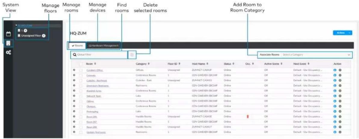
text_image
System View Manage floors Manage rooms Manage devices Find rooms Delete selected rooms Add Room to Room Category HQ-ZUM Rooms (3) Hardware Management Global Floor Associate Rooms Select a Category Room Category Floor ID Host Name Status Occ. Active Scene Next Event Action □ Garden Office Offsite Unassigned ZUMNET CASHF Online OR Default - Use Occupancy ... 1 □ Cinema Conference Rooms 1 CEN-CWEXER-EBCHF Online OR Default - Use Occupancy ... 1 □ Cinema/ Northwest Clickbox - East Unassigned ZUMNET CASH3 Online OR Default - Use Occupancy ... 1 □ Download Nextframe Rockets 1 CEN-CWEXER-EBCHF Online OR Default - Use Occupancy ... 1 □ Hundred Acts Conference Rooms 1 CEN-CWEXER-EBCHF Online OR Default - Use Occupancy ... 1 □ Network Team Late 1 CEN-CWEXER-EBCHF Online OR Default - Use Occupancy ... 1 □ Online Conference Rooms 1 CEN-CWEXER-EBCHF Online OR Default - Use Occupancy ... 1 □ Onsite... Conference Rooms 1 CEN-CWEXER-EBCHF Online OR Default - Use Occupancy ... 1 □ Hosting Late 1 CEN-CWEXER-EBCHF Online OR Default - Use Occupancy ... 1 □ Boost 20th Haddle Rooms Unassigned ZUMNET CASHF Online OR Default - Use Occupancy ... 1 □ Boost 20th Haddle Rooms Unassigned ZUMNET CASHT Online OR Default - Use Occupancy ... 1 □ Western Frontroom Rockets 1 CEN-CWEXER-EBCHF Online OR Default - Use Occupancy ...Manage Devices
In the System View, manage devices in the Hardware Management tab. Devices are divided into two categories: Wired and Wireless. Expand the Wireless menu to view and edit wireless devices. Expand the Wired menu to view and edit wired devices.
Rooms must be discovered by the ZUM-HUB4 before performing any procedure in this section. Refer to Discover Rooms on page 234.
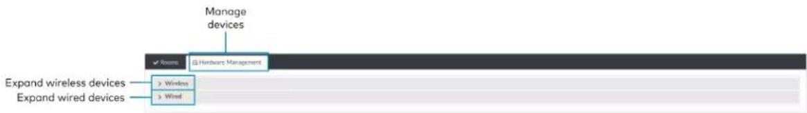
text_image
Manage devices ✓ Rooms Hardware Management Expand wireless devices > Windows > Wind Expand wired devicesWireless Devices
Access wireless gateways in the Hardware Management tab and expand the Wireless menu. View information about the gateway, assign Floor or Zone IDs, and identify or remove a gateway. To view, move, and delete the rooms assigned to the gateway, refer to Review Rooms Assigned to a Gateway on page 262.
Information about the gateway:
- Gateway Hostname: Displays the gateway's name.
• IP ID: Displays the gateway's IP ID. - Serial Number: Displays the gateway's serial number.
• IP Address: Displays the gateway's IP address.
• Floor ID: Refer to Assign a Floor ID to a Gateway on page 262.
• Zone ID: Refer to Assign a Floor ID to a Gateway on page 262.
• Action: Refer to Identify a Gateway on page 262 and Remove a Gateway on page 262.

text_image
Expand to show rooms assigned to a gateway. Browse Gate Room Name File ID Serial Number IP Address Floor ID Zone ID Active Assign Floor ID Assign Zone ID Identify gateway Remove gatewayAssign a Floor ID to a Gateway
Assigning a Floor ID to a gateway helps gateways discover wireless devices with the matching Floor ID. Set a device's Floor ID in the Zūm app before discovering the devices on the ZUM-HUB4. The Floor ID drop-down menu options are numbers -40 to +200 and Disabled. The Floor ID can be negative to indicate a floor below ground or positive to indicate a level above ground. Disabled categorizes the gateway to Unassigned Floor.

text_image
HQ-ZUM 1 ? Unassigned Floor 4Assign a Zone ID to a Gateway
To designate different areas of a floor as a zone, assign a gateway a Zone ID. Assigning a Zone ID to a gateway helps gateways discover wireless devices with the matching Zone ID. Set a device's Zone ID in the Zūm app before discovering the devices on the ZUM-HUB4. The Zone ID drop-down menu options are letter groupings AA to AZ and BA to BF.
Identify a Gateway
To identify a gateway, click . The SETUP LED on the gateway flashes.
Remove a Gateway
To delete a gateway, click . A confirmation window opens. Click Yes to delete the gateway, or No to keep the gateway.
Review Rooms Assigned to a Gateway
Click next to a gateway to view its assigned rooms:
• Netbridge: Lists assigned rooms.
- Status: Displays Online or Offline to show the device status.
• Floor ID: Inherits the Floor ID assigned to the gateway.
- Zone ID: Inherits the Zone ID assigned to the gateway
• Action: Move a room to a different gateway or remove a room.
- Click to move a room. The Move window opens.
■ Select the desired gateway from the drop-down menu.
- Click Move to move the room or Cancel to close the window without moving the room.
NOTE: Moving a room to a gateway with different a Floor ID or Zone ID changes the room's Floor ID or Zone ID to match the new gateway.
- Click to remove a room. A confirmation window opens. Click Yes to delete the room or Cancel to close the window without deleting the room.

text_image
Move Room to a different gateway Remove roomWired Devices
Access wired Room Access Points in the Hardware Management tab and expand the Wired menu. A Room Access Point (RAP) is the main device in the room. View information about the RAP, assign Floor or Zone IDs, or remove an RAP. To view devices connected to RAP, refer to Review RAP Components on page 264.
• Room Access Point Hostname: Displays the main device's name.
• IP ID: Displays the main device's IP ID.
- Serial Number: Displays the main device's serial number.
- IP Address: Displays the main device's IP address.
• Floor ID: Refer to Assign a Floor ID to an RAP on page 263.
• Zone ID: Refer to Assign a Zone ID to an RAP on page 264.
• Action: Refer to Remove a RAP on page 264.

text_image
List of load controllers Expand to show load controllers. Assign Floor ID Assign Zone ID Remove load controllerAssign a Floor ID to an RAP
Assigning a Floor ID to a load controller adds a floor to the Floor list. The Floor ID drop-down menu options are numbers -40 to +200 and Disabled. The Floor ID can be negative to indicate a floor below ground or positive to indicate a level above ground. Disabled categorizes the load controller to Unassigned Floor.
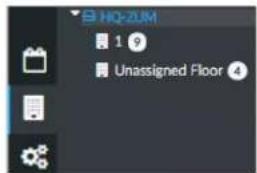
text_image
HQ-ZUM 1 9 Unassigned Floor 4Assign a Zone ID to an RAP
To designate different areas of a floor as a zone, assign a load controller a Zone ID. The Zone ID drop-down menu options are letter groupings AA to AZ and BA to BF.
Remove a RAP
To delete a load controller, click . A confirmation window opens. Click Yes to delete the load controller, or No to keep the load controller.
Review RAP Components
Click next to a load controller to view connected devices.
• Device: Displays child devices connected to the parent load controller.
• Status: Displays Online or Offline to show the child device's status.
• Cresnet ID: Displays the child device's Cresnet® control network ID.
- Serial Number: Displays the child device's serial number.
- Version: Displays the child device's current firmware version.
- Components: Click to view the child device components. Components displays the internal functions of a load controller, such as the internal occupancy sensors, photocell, and load controller, as well as other devices connected to the device, such as a keypad.
Name: For internal components, the name of the component is the device name plus the suffix "-1," "-2," or "-3."
■ -1: Load Controller component: Controls the connected loads.
-2: Occupancy sensor component: Uses occupancy to control the connected loads.
■ -3: Photocell component: Uses ambient light to control the connected loads.
■ Change the component name by using the Zūm App.
- Model: Displays the device model.
- Serial Number: Displays the component's serial number.
- Firmware Version: Displays the component's firmware version.
- Status: Displays Online or Offline to show the component's status.
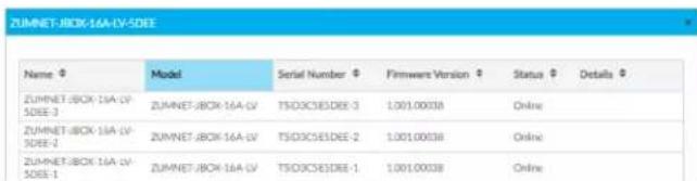
text_image
ZUMNET-BOX-16A-LV-5DEE Name Model Serial Number Firmware Version Status Details ZUMNET-BOX-16A-LV-5DEE-3 ZUMNET-BOX-16A-LV TSDXCS3DEE-3 1.001.00038 Online ZUMNET-BOX-16A-LV-5DEE-2 ZUMNET-BOX-16A-LV TSDXCS3DEE-2 1.001.00038 Online ZUMNET-BOX-16A-LV-5DEE-1 ZUMNET-BOX-16A-LV TSDXCS3DEE-1 1.001.00038 Online
text_image
View Show Base Access Field Hardware File (F) Initial Number File Address Filter (F) Save (F) Actions Device Status Current D Setup Number Device Components COMPTC1-0009 (M, 14.67.2003) 00000 15000000000 1255.8000 S COMPTC1-0009 (M, 14.67.2003) 00000 15000000000 1255.8000 S COMPTC1-0009 (M, 14.67.2003) 00000 15000000000 1233.8000 S Display componentsManage Settings
Access Settings in the Settings View. The Settings tab displays and allows you to edit the firmware, system time and location, network configuration, security configuration, and Crestron services.
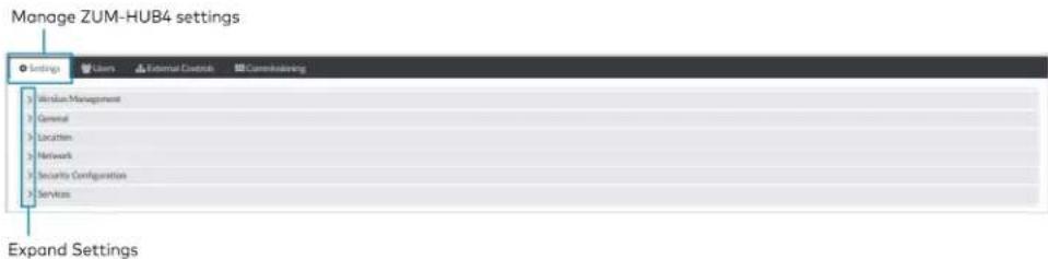
text_image
Manage ZUM-HUB4 settings Settings Windows Management General Location Network Security Configuration Services Expand SettingsVersion Management
Allows you to check for firmware updates for the ZUM-HUB4 and connected devices. Firmware updates for battery powered devices may take up to 24 hours. To update firmware:
-
Open Settings View.
-
Click Settings.
-
Click Version Management.
-
From Update Method, select Cloud or Removeable Media.
-
If using removable media, insert the device.
-
Check the box under Action for the devices whose firmware you want to update.
-
Click Update Now.

text_image
Zoom Hub Software Version 2.0001/0003 (Aug 17, 2023) Zoom Hub Software Version 1.0001/0004 Test Management - Active mode (Quoted) Log Table location URL (F) (A) Update Mode Closed List Checked: 18/25/2023 01:36:45.17 Host Name IP Address/NED Installed FIN Inv Available FIN Inv Date Include Room Devices Action Y-40 (ZEA) 18.35.72.57 2.000.0003 2.000.0009 Status Available N.A. CYELOOMEROSOCHAP 192.168.5.134 1.4449.00022 1.4449.00023 Up To Data N.A. CYELOOMEROSOCHAP 192.168.5.141 1.4449.00022 1.4449.00023 Up To Data N.A. ZLAHET-CADAS 192.168.5.137 1.000.00039 1.000.00039 Undated Available N.A. ZLAHET-CADAS 192.168.5.141 1.000.00039 Undated Available N.A. ZLAHET-CADAS 192.168.5.151 1.000.00039 Undated Available N.A. ZLAHET-CADAS 192.168.5.181 1.000.00038 Undated Available N.A.General
Displays the date, time, and time zone. To change the date and time:
-
Open Settings View.
-
Click Settings.
-
Click General.
-
Enter new values in the fields.
-
Click to save the changes or to discard changes.
NOTE: Changing these settings requires an immediate system reboot.
A confirmation windows opens. Click Yes to reboot or No to close the window.

text_image
Settings External Controls Customing 3. Version Management General Data Time Time Synthesis Enable Time Synthesis Time Server pack-injung Synthesis Now Time Configuration Time Date: LIPC-World Central Time ELS & Canada/ TimeOK/User format: 12:40 System Date/Time: 067.22.2015Location
Displays the location (latitude and longitude). Accurate location ensures the Sunrise/Sunset Schedule displays the correct sunrise and sunset times. To change the location:
- Open Settings View.
- Click Settings.
- Click Location.
- Enter new values in the fields.
- Click to save the changes or to discard changes.
NOTE: Changing these settings requires an immediate system reboot.
A confirmation windows opens. Click Yes to reboot or No to close the window.
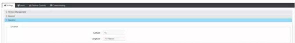
text_image
Settings Show External Context Consulting Service Management General Solution Location Latitude 0 Longitude -13972020Network
Displays the Ethernet settings. To change the Ethernet settings:
- Open Settings View.
- Click Settings.
- Click Network.
- Enter new values in the fields. Some fields are not available if DHCP is on.
- Click to save the changes or to discard changes.
NOTE: Changing these settings requires an immediate system reboot.
A confirmation windows opens. Click Yes to reboot or No to close the window.

text_image
Network Management General Network Ethernet Host Name: iG-2014 IP Address: iG-2014 Subtotal Work: iG-2014 Default Router: iG-2014 Domain: iG-2014 (Primary) or iG-2014 Primary DNS: iG-2014 Secondary DNS: iG-2014 WBS Server Secure Web Port: 44Security Configuration
Allows the user to change the device service password. To edit the password:
- Open Settings View.
- Click Settings.
- Click Security Configuration.
-
Click and to new values in the fields.
-
Click to save the changes or to discard changes.
A confirmation windows opens. Click Yes to reboot or No to close the window.

text_image
HVZHP • Direct security user account and password will respond to create authentication, then in your Windows. This help ensure your ZHP help environment. Device Service Status complementation Device Service Password UPServices
Displays Cloud Settings. To turn Cloud Configuration Service on or off:
- Open Settings View.
- Click Settings.
- Click Services. Cloud Configuration Service is on by default.
- To turn off Cloud Configuration Service, click the toggle.
- Click to save the changes or to discard changes.
NOTE: Changing these settings requires an immediate system reboot.
A confirmation windows opens. Click Yes to reboot or No to close the window.

text_image
Settings User General Controls Commutating 1. Version Management 2. General 3. Location 4. Network 5. Security Configuration 6. Services Cloud Settings Cloud Configuration ServiceManage Users
Access Users in the Settings View. The Users tab shows a list of all users and allows you to create new users and modify or delete existing users. The username must be 3 to 15 characters and are permitted to use uppercase letters (A-Z, lowercase letters (a-z), digits (0-9), and special characters (- () + [ ] . _). The password must be 8 to 12 characters is required to contain at least one uppercase letters (A-Z), lowercase letters (a-z), digits (0-9), and special characters (#!@\$%^&*-).

text_image
Manage Users Settings Users External Outputs Commissioning or Tools Local User Username Last Name First Name Email Group Action Creation User Hole email:publicdare.com Administration ☑ Facilities Cover Facilities bailitcshcompany.com Administration ☑ 0 New UserCreate a New User
To create a new User:
- Open Settings View.
- Click Users.
- Click . + New User
- Enter the user details.
- Click Save to save the new user or Cancel to exit without creating a new user.
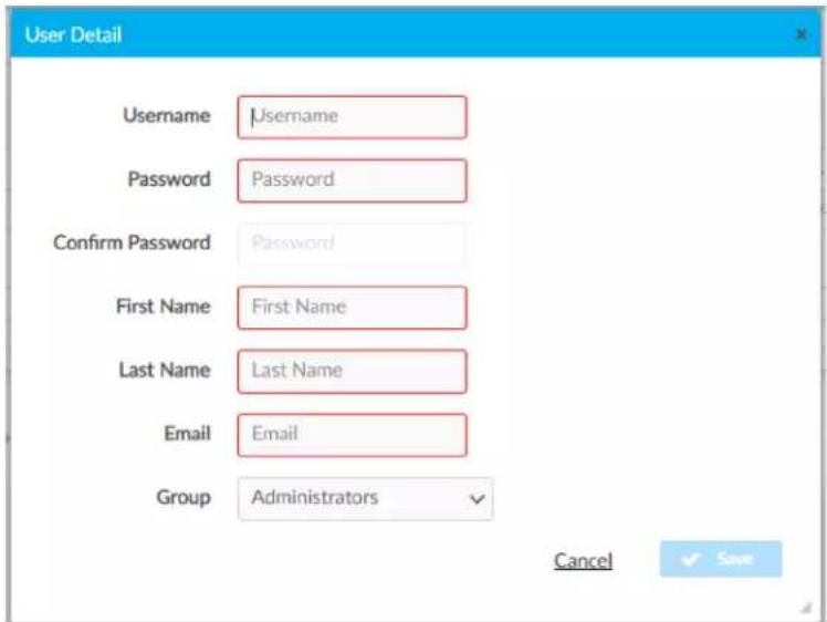
text_image
User Detail Username Username Password Password Confirm Password Password First Name First Name Last Name Last Name Email Email Group Administrators Cancel SaveConfigure an Existing User
To configure an existing User:
- Open Settings View.
-
Click Users.
-
Click next to the user.
- Update the user details.
- Click Save to save the changes or Cancel to exit without saving the changes.
Delete an Existing User
To delete an existing User:
- Open Settings View.
- Click Users.
- Click next to the user.
- Click Yes to delete the user or No to cancel without deleting the user.
External Users
For External Rooms to successfully connect, create a User and select ExternalUser from the Group drop-down menu. The Username and Password must match the credentials used for the SIMPL+® software module.
NOTES:
- SIMPL+® software modules are provided for use in commissioning a Crestron control system to work with the ZUM-HUB4. The software modules run within the control system program and provide virtual connections for all the necessary intersystem control signals. A separate dedicated module is required for each external and mirrored room. Control systems are limited in the number of modules supported, ranging from 0 to 2001000 depending on the model. For further assistance, please contact Crestron Commercial Lighting Support via email at clclighting@crestron.com or by calling 855-644-7643.
- Other Crestron control systems must be commissioned to provide the control logic required to communicate and operate as part of the Zūm network. Once integrated, each external room effectively becomes a part of the Zūm ecosystem.
Manage External Controls
Access External Controls in the Settings View. Use the External Controls tab to manage External Room settings. External Rooms provide the ability to integrate third-party devices into a Züm lighting control system. Refer to External Users on page 269 to create a User for External Rooms.
SIMPL+® software modules are provided for use in commissioning a Crestron control system to work with the ZUM-HUB4. The software modules run within the control system program and provide virtual connections for all the necessary intersystem control signals. A separate dedicated module is required for each external and mirrored room. Control systems are limited in the number of modules supported, ranging from 0 to 2001000 depending on the model. For further assistance, please contact Crestron Commercial Lighting Support via email at clclighting@crestron.com or by calling 855-644-7643.
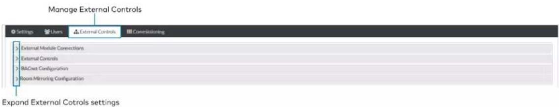
text_image
Manage External Controls Settings Users External Controls Commissoring External Module Connections External Controls BACnet Configuration Rooms Mimoring Configuration Expand External Cotrols settingsExternal Module Connections
To allow or prevent older versions of module to be used:
- Open Settings View.
- Click the External Controls tab and expand the External Module Connections menu.
- Click the toggle to turn Allow Legacy Module Connection on or off.
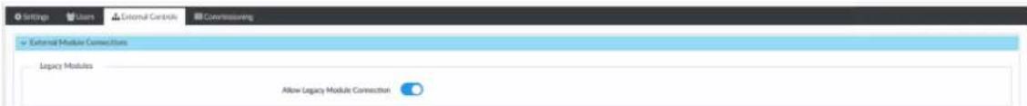
text_image
Settings User External Controls Commeasuring External Module Connections Legacy Modules Allow Legacy Module ConnectionExternal Controls
Access External Controls in the Settings View. Use the External Controls menu to add, edit, or delete a macro.
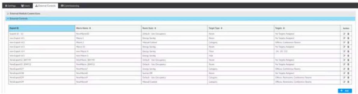
text_image
External Module Connections External Controls Export ID Export ID - 10 NewExport ID New Export ID New Export ID New Export ID New Export ID New Export ID New Export ID New Export ID New Export ID New Export ID New Export ID New Export ID New Export ID New Export ID New Export ID New Export ID New Export ID New Export ID New Export ID New Export ID New Export ID New Export ID New Export ID New Export ID New Export ID New Export ID New export ID New export ID New export ID New export ID New export ID New export ID New export ID New export ID New export ID New export ID New export ID New export ID New export ID New export ID New export ID New export ID New export ID New export ID New export ID New export ID New export ID New export ID New export ID New export ID New export ID New exports ID New exports ID New exports ID New exports ID New exports ID New exports ID New exports ID New exports ID New exports ID New exports ID New exports ID New exports ID New exports ID New exports ID New exports ID New exports ID New exports ID New exports ID New exports ID New exports ID New exports ID New exports ID New exports ID New exports ID New exports ID New export ID New export ID New export ID New export ID New export ID New export ID New export ID New export ID New export ID New export ID New export ID New export ID New export ID New export ID New export ID New export ID New export ID New export ID New export ID New export ID New export ID New export ID New export ID New export ID New output ID New output ID New output ID New output ID New output ID New output ID New output ID New output ID New output ID New output ID New output ID New output ID New output ID New output IDAdd Macro
To add a new macro:
-
Open Settings View.
-
Click the External Controls tab and expand the External Controls menu.
-
Click . A new row appears.
-
Configure the macros settings:
-
Enter the Export ID.
- Enter the Macro Name.
- Select a Room State.
• Target Type: Room Category, Room Floor, or Hub. -
Enter Targets.
-
Click to save or to cancel.

text_image
External Module Connections External Controls Export ID Name Name: 6 Output Type: 8 Target Type: 4 Target: 9 Action FrontExportID: 104418 HomeMatrix: 104418 Default -Use Discrepancy Position 12°Edit Existing Macro
To edit an existing macro:
- Open Settings View.
- Click the External Controls tab and expand the External Controls menu.
- Click .
- Enter new values in the fields.
- Click to save or to cancel.
Delete Existing Macro
To delete an existing macro:
- Open Settings View.
- Click the External Controls tab and expand the External Controls menu.
- Click 🔒 A confirmation window opens.
- Click Yes to delete the macro or No to cancel.
BACnet Configuration
The BACnet tab displays the system settings to establish a connection with the BMS (building management system). To configure BACnet service:
- Open Settings View.
- Click the External Controls tab and expand the BACnet Configuration menu.
3. Configure the BACnet settings:
NOTE: Use the search to find a specific room.
- BACnet Service: Click the toggle to turn the BACnet service on or off.
- Host ID: The ID that the ZUM-HUB4 uses when communicating with the BACnet system.
- Port Number: The port number that is used when communicating with the BACnet system.
- Export Settings: Export the BACnet settings to a CSV (comma separated value) file.
• Reserved Objects: Display objects that send signals to the ZUM-HUB4. - BACnet Enabled Rooms: The number of rooms with BACnet.
- Property List: Allows users to select which objects are enabled for all rooms.
• Room Name: The name of the room. - Base ID: Orders the device in the system and assigns the object IDs.
• ID Range: The range of Object IDs that the room can use. - Object List: Displays a list of all Object IDs, Object Names, and Object Types within the selected room. A blue checkmark indicates objects that are enabled.
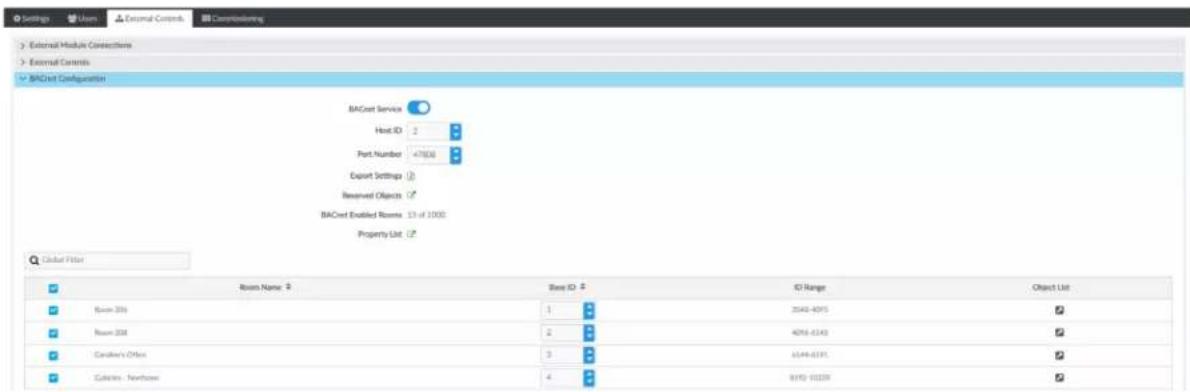
text_image
Settings Users External Controls Configuring External Module Connections External Contents BACest Configuration BACest Service Host ID 2 Port Number 47808 Export Settings Reserved Objects BACest Enabled Rooms 13 of 1000 Property List Global Filter Room Name: 2 Base ID: 2 ID Range Object List Room 204 Room 208 Cableton's Office Cableton - Nordbox 1 2 3 4 2040-4095 4096-6140 6144-6191 8195-10159Room Mirroring Configuration
Room Mirroring allows an external processor to send or receive information from an existing Zūm room.
- Open Settings View.
- Click the External Controls tab and expand the Room Mirroring Configuration menu.
- Click the toggle to turn Allow Mirroring on or off.
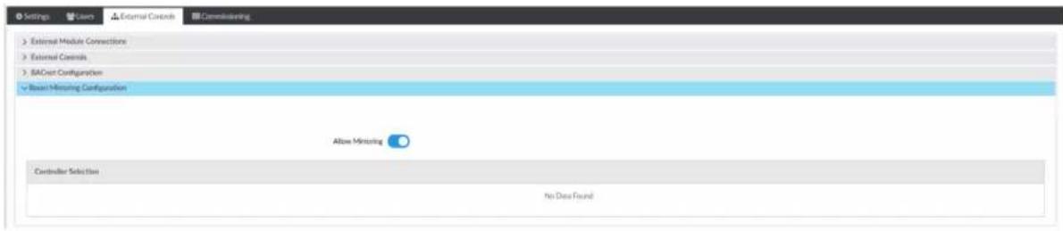
text_image
Settings Lawn External Controls Determining External Module Connections External Controls SACost Configuration Basic Menuing Configuration Above Menuing Controller Selection No Data FoundManage Commissioning
Access Commissioning in the Settings View. Use the Commissioning tab to manage, map, and deploy, room templates. To create a new template, use the Züm app.

text_image
Manage Commissioning Settings Users External Controls Commissions Template Management Mapping and Template Deployment Expand Commissioning settingsTemplate Management
Upload a new template or search, extract, edit, or delete an existing template.
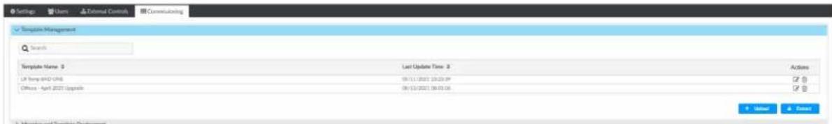
text_image
Settings Users External Controls Consulting Template Management Search Template Name: $ Last Update Time: $ Actions LP Temp: 042-015 09/11/2021 23:20:0P Office - April 2021 Upgrade 06/13/2021 08:03:16 + - + - + + + + + + + + + + + + + + + + + + + + + + + + + + + + + + + + + + + + + + + + + + + + + + + + + + +Add a New Template
To add a new room template:
- Open Settings View.
- Click the Commissioning tab and expand the Template Management menu.
- Click Upload. The Upload window opens.
- Click Choose to browse for a new template.
- Select the template.
- Click Upload to add the template to the Template Management menu, Cancel to choose a different template, or Close to close the window without adding a new template.
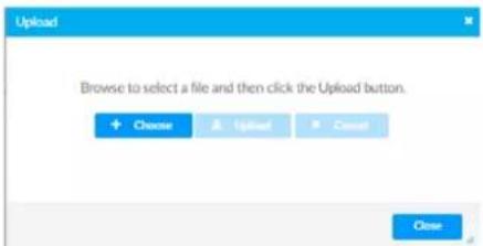
text_image
Upload Browse to select a file and then click the Upload button. + Choose & Upload Cancel CloseEdit Template Name
To edit an existing template name:
- Open Settings View.
- Click the Commissioning tab and expand the Template Management menu.
- If necessary, use the Search bar to find a room template.
- Click
-
Type the new name.
-
Click Save to save the new name or Cancel to close the window without saving a new name.
Delete Existing Template
To delete an existing template:
- Open Settings View.
- Click the Commissioning tab and expand the Template Management menu.
- If necessary, use the Search bar to find a room template.
- Click 🔒 A confirmation window opens.
- Click Yes to delete the template or Cancel to close the window.
Extract Template
To extract a room template from another room:
- Open Settings View.
- Click the Commissioning tab and expand the Template Management menu.
- If necessary, use the Search bar to find a room template.
- Click Extract. The Extract Template window opens.
- Select a room.
- Click Extract to extract the template or Cancel to close the window.
Mapping and Template Deployment
Use Mapping and Template Deployment to apply and deploy templates to rooms and to import mapping files.

text_image
Template Management Mapping and Template Employment Search File Comercisational Resource Serial Number Room Status Room Name Last Applied Template Pending Template Actions CD456A073 Cablec - Hardware ✓ T1028C35D03 Rave 208 ✓ CD456A047 Cablec Office ✓ CD456A015 Rave 908 ✓ CD456A046 Cablec Software ✓ CD456A076 Cablec Software ✓Apply and Deploy Templates.
To apply and deploy a template:
- Open Settings View.
- Click the Commissioning tab and expand the Mapping and Template Deployment menu.
- Select a room or multiple rooms. If necessary, use the Search bar to find a room.
- From the Select a template drop-down menu, choose the desired template.
-
Click Apply Template. When the template is successfully applied, the template is now pending.
-
Click Deploy Selected to deploy the template to the rooms or Clear Pending to remove the template from the rooms.
Edit Template Assignment
To edit a template assignment:
- Open Settings View.
- Click the Commissioning tab and expand the Mapping and Template Deployment menu.
- Click beside the desired room. If necessary, use the Search bar to find the room. A window opens.
- From the Select Template drop-down menu, choose the desired template.
The remaining data specifies the room information, the devices and components affected, and the selected template details.
- Click Save to reassign the room template or Cancel to close the window without saving.

text_image
Name Name: C#.N## (A##) Model Name: Device Name: ID: 35 Serial Number: Model Name: Device Name: ID: 120000000 Serial Number: Device Name: Device Name: Device Name: Device Name: Device Name: Device Name: Device Name: Device Name: Device Name: Device Name: Device Name: Device Name: Device Name: Device Name: Device Name: Device Name: Device Name: Device Name: Device Name: Device Name: Device Name: Device Name: Device Name: Device Name: Device Name: Device NAME Component Name: Component Type: Analyzed: 1 ZHP-801-802 2 ZHP-801-802 3 ZHP-801-802 4 ZHP-801-802 5 ZHP-801-802 6 ZHP-801-802 7 ZHP-801-802 8 ZHP-801-802 9 ZHP-801-802 10 ZHP-801-802 11 ZHP-801-802 12 ZHP-801-802 13 ZHP-801-802 14 ZHP-801-802 15 ZHP-801-802 16 ZHP-801-802 17 ZHP-801-802 18 ZHP-801-802 19 ZHP-801-802 20 ZHP-801-802 21 ZHP-801-802 22 ZHP-801-802 23 ZHP-801-802 24 ZHP-801-802 25 ZHP-801-802 26 ZHP-801-802 27 ZHP-801-802 28 ZHP-801-802 29 ZHP-801-802 30 ZHP-801-802 31 ZHP-801-802 32 ZHP-801-802 33 ZHP-801-802 34 ZHP-801-802 35 ZHP-801-802 36 ZHP-801-802 37 ZHP-801-802 38 ZHP-801-802 39 ZHP-801-802 40 ZHP-801-802 41 ZHP-801-802 42 ZHP-801-802 43 ZHP-801-802 44 ZHP-801-802 45 ZHP-801-802 46 ZHP-801-802 47 ZHP-801-802 48 ZHP-801-802 49 ZHP-801-802 50 ZHP-801-802 51 ZHP-801-802 52 ZHP-801-802 53 ZHP-801-802 54 ZHP-801-802 55 ZHP-801-802 56 ZHP-801-802 57 ZHP-801-802 58 ZHP-801-802 59 ZHP-801-802 60 ZHP-801-802 61 ZHP-801-802 62 ZHP-801-802 63 ZHP-801-802 64 ZHP-801-802 65 ZHP-801-802 66 ZHP-801-802 67 ZHP-801-802 68 ZHP-801-802 69 ZHP-801-802 70 ZHP-801-802 71 ZHP-801-802 72 ZHP-801-802 73 ZHP-801-802 74 ZHP-801-802 75 ZHP-801-802 76 ZHP-801-802 77 ZHP-801-802 78 ZHP-801-802 79 ZHP-801-802 80 ZHP-801-802 B jnter n## C jnter n## C jnter n## C jnter n## C jnter n## C jnter n## C jnter n## C jnter n## C jnter n## C jnter n## C jnter n## C jnter n## C jnter n## C jnter n## C jnter n## C jnter n## C jnter n## C jnter m## C jnter m## C jnter m## C jnter m## C jnter m## C jnter m## C jnter m## C jnter m## C jnter m## C jnter m## C jnter m## C jnter m## C jnter m## C jnter m## C jnter m## C jnter m## C jnter m## C junters# C junters# C junters# C junters# C junters# C junters# C junters# C junters# C junters# C junters# C junters# C junters# C junters# C junters# C junters# C junters# C junters# C junters# C junters# C junters# C junters#Import Mapping File
Access Import Mapping File in the Settings View. Open the Commissioning tab and expand the Mapping and Template Deployment menu. If a mapping file has been created in an external file, use the Import Mapping File button to navigate to the mapping and import the file.
Review Device Information and Status
View the Demand Response status, system alerts, help information, or sign out of the web interface.
Demand Response Status
Demand Response is enabled.
Demand Response is disabled.
System Information
Displays system alerts.
Help
Click to view the help file.
Sign Out

Click to bring up the Sign Out pop-up. Click Sign Out to log out of the ZUM-HUB4.
Reboot ZUM-HUB4
To reboot the ZUM-HUB4:
- Click the Actions menu
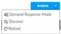
- Click Reboot. The Confirmation window opens.
text_image
Confirmation Are you sure you want to reboot? ✓ Yes ✗ No- Click Yes to Reboot or No to close the window without rebooting.
Resources
Below are resources provided for Crestron Züm® Wired Lighting Control.
NOTE: You may need to provide your Crestron.com web account credentials when prompted to access some of the following resources.
Crestron Support and Training
- Crestron True Blue Support
• Crestron Resource Library
• Crestron Online Help (OLH)
Crestron Zum® Lighting Answer Index: Answer ID: 1001872
• Crestron Training Institute (CTI) Portal
Programmer and Developer Resources
- help.crestron.com: Provides help files for Crestron programming tools such as SIMPL, SIMPL#, and Crestron Toolbox™ software
• developer.crestron.com: Provides developer documentation for Crestron APIs, SDKs, and other development tools
Product Certificates
To search for product certificates, refer to support.crestron.com/app/certificates.
Related Documentation
Energy standards for Zūm Wired solutions
IECC 2021
• Education Applications
• Healthcare Applications
• Hospitality Applications
• Office Applications
• Restaurant Applications
• Retail Applications
ASHRAE 2019
• Education Applications
• Healthcare Applications
• Hospitality Applications
• Office Applications
• Restaurant Applications
• Retail Applications
Title 24 2019
• Education Applications
• Healthcare Applications
• Hospitality Applications
• Office Applications
• Restaurant Applications
• Retail Applications
IECC 2018
• Education Applications
• Healthcare Applications
• Hospitality Applications
• Office Applications
• Restaurant Applications
• Retail Applications
Models
Below are the available products for Crestron Zūm® Wired Lighting Control.
Load Controllers
| Part Number Model Description | |
| 6511166 ZUMNET-JBOX-16A-LV Zūm® Wired J-Box Load Controller, 0-10V Dimmer, 16A, 100-277V with Net and Link Communication | |
| 6511170 ZUMNET-JBOX-DALI Zūm® Wired J-Box Controller with DALI® Drivers, 120-277V with Net and Link Communication | |
| 6511167 ZUMLINK-JBOX-16A-LV Zūm® Wired J-Box Load Controller, 0-10V Dimmer, 16A, 100-277V with Link Communication | |
| 6511168 ZUMLINK-JBOX-20A-SW Zūm® Wired J-Box Load Controller, High Inrush Switch, 20A, 100-277V with Link Communication | |
| 6511169 ZUMLINK-JBOX-20A-PLUG Zūm® Wired J-Box Load Controller, Plug Load Switch, 20A, 100-277VAC with Link Communication | |
| 6512078 ZUMLINK-EXP-16A-DIMU | Zūm® Wired Universal Dimmer Load Controller |
Keypad
| Part Number | Model | Description |
| 6511187 | ZUMLINK-KP-R-W | Zūm® Wired Keypad with Link Communication, Rocker Button |
Presence Detectors
| Part Number | Model | Description |
| 6511729 | ZUMLINK-IR-QUATTRO-DLS | Züm^® Wired Infrared Presence Detector with Daylight Sensing and Link Communication |
| 6511730 | ZUMLINK-DT-QUATTRO-DLS | Züm^® Wired Dual-Tech Presence Detector with Daylight Sensing and Link Communication |
| 6511731 | ZUMLINK-US-QUATTRO-DLS | Züm^® Wired Ultrasonic Presence Detector with Daylight Sensing and Link Communication |
| Part Number | Model Description |
| 6511732 | ZUMLINK-IR-QUATTRO-HD-DLS Züm® Wired High-Definition InfraredPresence Detector with Daylight Sensing and Link Communication |
| 6511733 | ZUMLINK-US-HALLWAY-DLS Züm® Wired Ultrasonic Dual-DirectionHallway Presence Detector with Daylight Sensing and Link Communication |
| 6511734 | ZUMLINK-US-ONEWAY-DLS Züm® Wired Ultrasonic Single-DirectionHallway Presence Detector with Daylight Sensing and Link Communication |
| 6511735 | ZUMLINK-IR-QUATTRO-DLS-RLY Züm® Wired Infrared Presence Detectorwith Daylight Sensing, HVAC Control, and Link Communication |
| 6511736 | ZUMLINK-DT-QUATTRO-DLS-RLY Züm® Wired Dual-Tech Presence Detectorwith Daylight Sensing, HVAC Control, and Link Communication |
| 6511737 | ZUMLINK-US-QUATTRO-DLS-RLY Züm® Wired Ultrasonic Presence Detectorwith Daylight Sensing, HVAC Control, and Link Communication |
| 6511738 | ZUMLINK-IR-QUATTRO-HD-DLS-RLY Züm® Wired High-Definition InfraredPresence Detector with Daylight Sensing, HVAC Control, and Link Communication |
| 6511739 | ZUMLINK-US-HALLWAY-DLS-RLY Züm® Wired Ultrasonic Dual-DirectionHallway Presence Detector with Daylight Sensing, HVAC Control, and Link Communication |
| 6511740 | ZUMLINK-US-ONEWAY-DLS-RLY Züm® Wired Ultrasonic Single-DirectionHallway Presence Detector with Daylight Sensing, HVAC Control, and Link Communication |
Hub and Kits
| Part Number | Model | Description |
| 6511480 ZUM-HUB4 | 4-SeriesTM Control Processor for Zūm® Lighting Control System | |
| 6512648 ZUML-HUB4-GW | 4-SeriesTM Control Processor for Zūm® Lighting Control System with Wireless Gateway and Power Supply | |
| 6512646 ZUML-HUB4-PAK | Zūm® Lighting Control Processor Panel, Basic | |
| 6512647 ZUML-HUB4-CN-PAK | Zūm® Lighting Control Processor Panel, Expanded | |
Software
Part Number Model Description
CRESTRON-ZUM Crestron Zūm® Lighting Configuration App
3002182 SW-HUB4-PROG Custom Program License for ZUM-HUB4
Power Supply
Part Number Model Description
6512056 ZUMLINK-JBOX-PSU Zūm® Wired J-Box Power Supply
Cables
Part Number Model Description
| 6511388 | CBL-CAT5E-ZUMNET-P-25 | CAT5e Cable with Net Communication for LAN Wiring Zūm^ Control Systems, Plenum, Purple, 25 ft |
| 6511389 | CBL-CAT5E-ZUMNET-P-50 | CAT5e Cable with Net Communication for LAN Wiring Zūm^ Control Systems, Plenum, Purple, 50 ft |
| 6511390 | CBL-CAT5E-ZUMNET-P-100 | CAT5e Cable with Net Communication for LAN Wiring Zūm^ Control Systems, Plenum, Purple, 100 ft |
| 6512907 | CBL-CAT5E-ZUMNET-P-SP500 | CAT5e Cable with Net Communication for LAN Wiring Zūm^ Control Systems, Plenum, Purple, 500 ft, Spool |
| 6511393 | CBL-CAT5E-ZUMLINK-P-0.5 | CAT5e Cable with Link Communication for In-Room Wiring Zūm^ Control Systems, Plenum, Orange, 6 in |
| 6511394 | CBL-CAT5E-ZUMLINK-P-3 | CAT5e Cable with Link Communication for In-Room Wiring Zūm^ Control Systems, Plenum, Orange, 3 ft |
| 6511395 | CBL-CAT5E-ZUMLINK-P-6 | CAT5e Cable with Link Communication for In-Room Wiring Zūm^ Control Systems, Plenum, Orange, 6 ft |
| 6511396 | CBL-CAT5E-ZUMLINK-P-12 | CAT5e Cable with Link Communication for In-Room Wiring Zūm^ Control Systems, Plenum, Orange, 12 ft |
| 6511397 | CBL-CAT5E-ZUMLINK-P-25 | CAT5e Cable with Link Communication for In-Room Wiring Zūm^ Control Systems, Plenum, Orange, 25 ft |
| 6511398 | CBL-CAT5E-ZUMLINK-P-50 | CAT5e Cable with Link Communication for In-Room Wiring Zūm^ Control Systems, Plenum, Orange, 50 ft |
| 6511617 | CBL-CAT5E-ZUMLINK-P-12-10PK | CAT5e Cable with Link Communication for In-Room Wiring Zūm^ Control Systems, Plenum, Orange, 12 ft, 10 Pack |
| Part Number Model Description | |
| 6511618 CBL-CAT5E-ZUMLINK-P-25-10PK | CAT5e Cable with Link Communication for In-Room Wiring Zūm® Control Systems, Plenum, Orange, 25 ft, 10 Pack |
| 6512908 CBL-CAT5E-ZUMLINK-P-SP500 | CAT5e Cable with Link Communication for In-Room Wiring Zūm® Control Systems, Plenum, Orange, 500 ft, Spool |
Cable Accessories
| Part Number Model Description |
| 6512025 ZUMLINK-CONV-CN Zūm® Wired Adapter Cable for Cresnet® Devices |
| 6512080 ZUMLINK-SPLTR-RJ45 Zūm® Wired RJ-45 Splitter |
Rocker and Button Trees
| Part Number Model Description | ||
| 6511193 ZUMLINK-BTNR-WENGRAVED | Rocker Button with Bezel for Züm^ Light Control Keypads (ZUMLINK-KP), Engraved, White | |
| 6511194 ZUMLINK-BTNR-BENGRAVED | Rocker Button with Bezel for Züm^ Light Control Keypads (ZUMLINK-KP), Engraved, Black | |
| 6511195 ZUMLINK-BTNR-AENGRAVED | Rocker Button with Bezel for Züm^ Light Control Keypads (ZUMLINK-KP), Engraved, Almond | |
| 6511196 ZUMLINK-BTNR-GENGRAVED | Rocker Button with Bezel for Züm^ Light Control Keypads (ZUMLINK-KP), Engraved, Gray | |
| 6511197 ZUMLINK-BTNR-RENGRAVED | Rocker Button with Bezel for Züm^ Light Control Keypads (ZUMLINK-KP), Engraved, Red | |
| 6512412 ZUMLINK-BTN2-WENGRAVED | Two Button Tree with Bezel for Züm^ Light Control Keypads (ZUMLINK-KP), Engraved, White | |
| 6512413 ZUMLINK-BTN2-BENGRAVED | Two Button Tree with Bezel for Züm^ Light Control Keypads (ZUMLINK-KP), Engraved, Black | |
| 6512414 ZUMLINK-BTN2-AENGRAVED | Two Button Tree with Bezel for Züm^ Light Control Keypads (ZUMLINK-KP), Engraved, Almond | |
| 6512415 ZUMLINK-BTN2-GENGRAVED | Two Button Tree with Bezel for Züm^ Light Control Keypads (ZUMLINK-KP), Engraved, Gray | |
| 6512416 ZUMLINK-BTN2-RENGRAVED | Two Button Tree with Bezel for Züm^ Light Control Keypads (ZUMLINK-KP), Engraved, R | |
| 6511203 ZUMLINK-BTN4-WENGRAVED | Four Button Tree with Bezel for Züm^ Light Control Keypads (ZUMLINK-KP), Engraved, White | |
| 6511204 ZUMLINK-BTN4-BENGRAVED | Four Button Tree with Bezel for Züm^ Light Control Keypads (ZUMLINK-KP), Engraved, Black | |
| 6511205 ZUMLINK-BTN4-AENGRAVED | Four Button Tree with Bezel for Züm^ Light Control Keypads (ZUMLINK-KP), Engraved, Almond | |
| 6511206 ZUMLINK-BTN4-GENGRAVED | Four Button Tree with Bezel for Züm^ Light Control Keypads (ZUMLINK-KP), Engraved, Gray | |
| 6511207 ZUMLINK-BTN4-RENGRAVED | Four Button Tree with Bezel for Züm^ Light Control Keypads (ZUMLINK-KP), Engraved, Red | |
| 6511213 ZUMLINK-BTN6-WENGRAVED | Six Button Tree with Bezel for Züm^ Light Control Keypads (ZUMLINK-KP), Engraved, White | |
| 6511214 ZUMLINK-BTN6-BENGRAVED | Six Button Tree with Bezel for Züm^ Light Control Keypads (ZUMLINK-KP), Engraved, Black | |
| 6511215 ZUMLINK-BTN6-AENGRAVED | Six Button Tree with Bezel for Züm^ Light Control Keypads (ZUMLINK-KP), Engraved, Almond | |
| 6511216 ZUMLINK-BTN6-GENGRAVED | Six Button Tree with Bezel for Züm^ Light Control Keypads (ZUMLINK-KP), Engraved, Gray | |
| 6511217 ZUMLINK-BTN6-RENGRAVED | Six Button Tree with Bezel for Züm^ Light Control Keypads (ZUMLINK-KP), Engraved,Red | |
| 6511223 ZUMLINK-BTN8-WENGRAVED | Eight Button Tree with Bezel for Züm^ Light Control Keypads (ZUMLINK-KP), Engraved, White | |
| 6511224 ZUMLINK-BTN8-BENGRAVED | Eight Button Tree with Bezel for Züm^ Light Control Keypads (ZUMLINK-KP), Engraved, Black | |
| 6511225 ZUMLINK-BTN8-AENGRAVED | Eight Button Tree with Bezel for Züm^ Light Control Keypads (ZUMLINK-KP), Engraved, Almond | |
| 6511226 ZUMLINK-BTN8-GENGRAVED | Eight Button Tree with Bezel for Züm^ Light Control Keypads (ZUMLINK-KP), Engraved, Gray | |
| 6511227 ZUMLINK-BTN8-RENGRAVED | Eight Button Tree with Bezel for Züm^ Light Control Keypads (ZUMLINK-KP), Engraved, Engraved, Red | |
| 6512417 ZUMLINK-BTN2-W Two Button Tree with Bezel for Züm^ Light Control Keypads (ZUMLINK-KP), Pad Printed, White | ||
| 6512418 ZUMLINK-BTN2-B Two Button Tree with Bezel for Züm^ Light Control Keypads (ZUMLINK-KP), Pad Printed, Black | ||
| 6512419 ZUMLINK-BTN2-A Two Button Tree with Bezel for Züm^ Light Control Keypads (ZUMLINK-KP), Pad Printed, Almond | ||
| 6512420 ZUMLINK-BTN2-G Two Button Tree with Bezel for Züm^ Light Control Keypads (ZUMLINK-KP), Pad Printed, Gray | ||
| 6512421 ZUMLINK-BTN2-R Two Button Tree with Bezel for Züm^ Light Control Keypads (ZUMLINK-KP), Pad Printed, Red | ||
| 6511233 ZUMLINK-BTN4-W Four Button Tree with Bezel for Zūm® Light Control Keypads (ZUMLINK-KP), Pad Printed, White | ||
| 6511234 ZUMLINK-BTN4-B Four Button Tree with Bezel for Zūm® Light Control Keypads (ZUMLINK-KP), Pad Printed, Black | ||
| 6511235 ZUMLINK-BTN4-A Four Button Tree with Bezel for Zūm® Light Control Keypads (ZUMLINK-KP), Pad Printed, Almond | ||
| 6511236 ZUMLINK-BTN4-G Four Button Tree with Bezel for Zūm® Light Control Keypads (ZUMLINK-KP), Pad Printed, Gray | ||
| 6511237 ZUMLINK-BTN4-R Four Button Tree with Bezel for Zūm® Light Control Keypads (ZUMLINK-KP), Pad Printed, Red | ||
| 6511238 ZUMLINK-BTN6-W Six Button Tree with Bezel for Zūm® Light Control Keypads (ZUMLINK-KP), Pad Printed, White | ||
| 6511239 ZUMLINK-BTN6-B Six Button Tree with Bezel for Zūm® Light Control Keypads (ZUMLINK-KP), Pad Printed, Black | ||
| 6511240 ZUMLINK-BTN6-A Six Button Tree with Bezel for Zūm® Light Control Keypads (ZUMLINK-KP), Pad Printed, White | ||
| 6511241 ZUMLINK-BTN6-G Six Button Tree with Bezel for Zūm® Light Control Keypads (ZUMLINK-KP), Pad Printed, Gray | ||
| 6511242 ZUMLINK-BTN6-R Six Button Tree with Bezel for Zūm® Light Control Keypads (ZUMLINK-KP), Pad Printed, Red | ||
| 6511243 ZUMLINK-BTN8-W Eight Button Tree with Bezel for Zūm® Light Control Keypads (ZUMLINK-KP), Pad Printed White | ||
| 6511244 ZUMLINK-BTN8-B Eight Button Tree with Bezel for Zūm® Light Control Keypads (ZUMLINK-KP), Pad Printed, Black | ||
| 6511245 ZUMLINK-BTN8-A Eight Button Tree with Bezel for Zūm® Light Control Keypads (ZUMLINK-KP), Pad Printed, Almond | ||
| 6511246 ZUMLINK-BTN8-G Eight Button Tree with Bezel for Zūm® Light Control Keypads (ZUMLINK-KP), Pad Printed, Gray | ||
| 6511247 ZUMLINK-BTN8-R Eight Button Tree with Bezel for Zūm® Light Control Keypads (ZUMLINK-KP), Pad Printed, Red | ||
| 6511188 ZUMLINK-BTNR-W BLANK | Rocker Button with Bezel for Zūm® Light Control Keypads (ZUMLINK-KP), Blank, White | |
| 6511189 ZUMLINK-BTNR-B BLANK | Rocker Button with Bezel for Zūm® Light Control Keypads (ZUMLINK-KP), Blank, Black | |
| 6511190 ZUMLINK-BTNR-A BLANK | Rocker Button with Bezel for Zūm® Light Control Keypads (ZUMLINK-KP), Blank, Almond | |
| 6511191 ZUMLINK-BTNR-G BLANK | Rocker Button with Bezel for Zūm® Light Control Keypads (ZUMLINK-KP), Blank, Gray | |
| 6511192 ZUMLINK-BTNR-R BLANK | Rocker Button with Bezel for Zūm^® Light Control Keypads (ZUMLINK-KP), Blank, Red | |
| 6512574 ZUMLINK-BTN2-W BLANK | Two Button Tree with Bezel for Zūm^® Light Control Keypads (ZUMLINK-KP), Blank, White | |
| 6512575 ZUMLINK-BTN2-B BLANK | Two Button Tree with Bezel for Zūm^® Light Control Keypads (ZUMLINK-KP), Blank, Black | |
| 6512576 ZUMLINK-BTN2-A BLANK | Two Button Tree with Bezel for Zūm^® Light Control Keypads (ZUMLINK-KP), Blank, Almond | |
| 6512577 ZUMLINK-BTN2-G BLANK | Two Button Tree with Bezel for Zūm^® Light Control Keypads (ZUMLINK-KP), Blank, Gray | |
| 6512578 ZUMLINK-BTN2-R BLANK | Two Button Tree with Bezel for Zūm^® Light Control Keypads (ZUMLINK-KP), Blank, Red | |
| 6512579 ZUMLINK-BTN4-W BLANK | Four Button Tree with Bezel for Zūm^® Light Control Keypads (ZUMLINK-KP), Blank, White | |
| 6512580 ZUMLINK-BTN4-B BLANK | Four Button Tree with Bezel for Zūm^® Light Control Keypads (ZUMLINK-KP), Blank, Black | |
| 6512581 ZUMLINK-BTN4-A BLANK | Four Button Tree with Bezel for Zūm^® Light Control Keypads (ZUMLINK-KP), Blank, Almond | |
| 6512582 ZUMLINK-BTN4-G BLANK | Four Button Tree with Bezel for Zūm^® Light Control Keypads (ZUMLINK-KP), Blank, Gray | |
| 6512583 ZUMLINK-BTN4-R BLANK | Four Button Tree with Bezel for Zūm^® Light Control Keypads (ZUMLINK-KP), Blank, Red | |
| 6512584 ZUMLINK-BTN6-W BLANK | Six Button Tree with Bezel for Zūm^® Light Control Keypads (ZUMLINK-KP), Blank, White | |
| 6512585 ZUMLINK-BTN6-B BLANK | Six Button Tree with Bezel for Zūm^® Light Control Keypads (ZUMLINK-KP), Blank, Black | |
| 6512586 ZUMLINK-BTN6-A BLANK | Six Button Tree with Bezel for Zūm^® Light Control Keypads (ZUMLINK-KP), Blank, Almond | |
| 6512587 ZUMLINK-BTN6-G BLANK | Six Button Tree with Bezel for Zūm^® Light Control Keypads (ZUMLINK-KP), Blank, Gray | |
| 6512588 ZUMLINK-BTN6-R BLANK | Six Button Tree with Bezel for Zūm^® Light Control Keypads (ZUMLINK-KP), Blank, Red | |
| 6512589 ZUMLINK-BTN8-W BLANK | Eight Button Tree with Bezel for Zūm^® Light Control Keypads (ZUMLINK-KP), Blank, White | |
| 6512590 ZUMLINK-BTN8-B BLANK | Eight Button Tree with Bezel for Zūm^® Light Control Keypads (ZUMLINK-KP), Blank, Black | |
| 6512591 ZUMLINK-BTN8-A BLANK | Eight Button Tree with Bezel for Zūm^® Light Control Keypads (ZUMLINK-KP), Blank, Almond | |
| 6512592 ZUMLINK-BTN8-GBLANK | Eight Button Tree with Bezel for Zūm^ Light Control Keypads (ZUMLINK-KP), Blank, Gray | |
| 6512593 ZUMLINK-BTN8-RBLANK | Eight Button Tree with Bezel for Zūm^ Light Control Keypads (ZUMLINK-KP), Blank, Red | |
This page is intentionally left blank.