
NA-F095 - Washing machine SHARP - Free user manual and instructions
Find the device manual for free NA-F095 SHARP in PDF.
| Product type | Washing machine |
| Brand | Sharp |
| Model | NA-F095 |
| Washing capacity | 7 kg |
| Energy class | A+ |
| Maximum spin speed | 1000 rpm |
| Number of programs | 15 |
| Dimensions (H x W x D) | 85 x 60 x 60 cm |
| Net weight | 60 kg |
| Power supply | 220-240 V, 50 Hz |
| Water consumption per cycle | 50 L |
| Energy consumption per cycle | 0.95 kWh |
| Noise level (wash/spin) | 58 / 76 dB |
| Drum type | Stainless steel |
| Special functions | Delayed start, Quick wash, Child lock |
| Maintenance and cleaning | Clean the filter after each cycle, descale the drum every 3 months |
| Safety | Overload detection, door lock, anti-foam protection |
| Spare parts and repairability | Repairability index 7.5/10, parts available for 5 years |
| General information | 2 years warranty, made in Europe |
Frequently Asked Questions - NA-F095 SHARP
User questions about NA-F095 SHARP
0 question about this device. Answer the ones you know or ask your own.
Ask a new question about this device
Download the instructions for your Washing machine in PDF format for free! Find your manual NA-F095 - SHARP and take your electronic device back in hand. On this page are published all the documents necessary for the use of your device. NA-F095 by SHARP.
USER MANUAL NA-F095 SHARP
Module Registration = Guarantee
natural_image
Simple yellow sun icon with plus and minus signs on blue background (no text or symbols)ScottyPro for free!
For the first 100 registrations (NA 1,05 m²) Gratis für die ersten 100 Registrierungen (NA 1,05 m²) Gratuit pour les 100 premiers enregistrements (NA 1,05 m²) Gratis para los 100 primeros registros (NA 1,05 m²)
natural_image
Black electronic device with blue screen displaying 'ARP' and a white cover, placed on a grid mat (no visible text or symbols on device body)
FSC
Mixed Sources
Product group from well-managed forests and other controlled sources www.fsc.org Cert no. GFA-COC-001611 © 1996 Forest Stewardship Council
This brochure is printed on FSC-certified paper.
Module Registration = Guarantee!
Thank you for choosing Sharp NA series thin-film photovoltaic modules.
Both you and the environment will benefit from this decision. In addition to high product quality from Sharp, you receive customer-focused service and guarantee package: the Sharp module registration.
For more information, please turn to pages 4 – 11
You register – we guarantee.
Registration of Sharp thin-film modules (NA series) certifies the plant operator's rights to comprehensive guarantee services from Sharp.
Register Sharp thin-film modules online at www.brandaddedvalue.net.
For registration of modules by post, please use the registration form on pages 9 and 10.
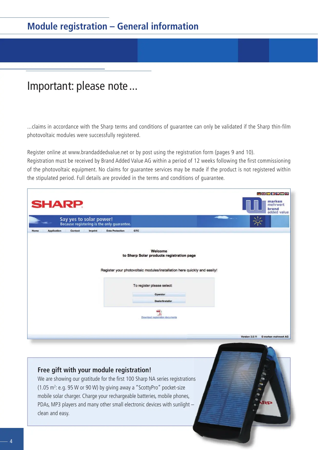
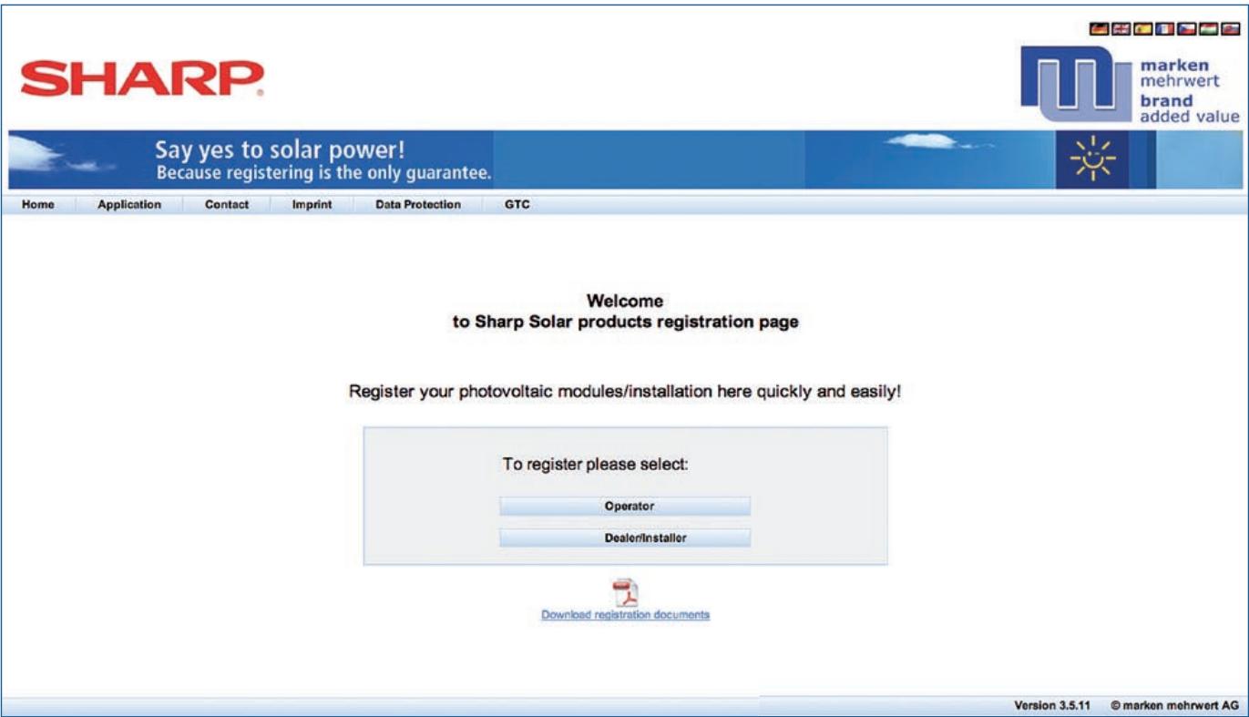
Important: please note ...
...claims in accordance with the Sharp terms and conditions of guarantee can only be validated if the Sharp thin-film photovoltaic modules were successfully registered.
Register online at www.brandaddedvalue.net or by post using the registration form (pages 9 and 10).
Registration must be received by Brand Added Value AG within a period of 12 weeks following the first commissioning of the photovoltaic equipment. No claims for guarantee services may be made if the product is not registered within the stipulated period. Full details are provided in the terms and conditions of guarantee.
Free gift with your module registration!
We are showing our gratitude for the first 100 Sharp NA series registrations (1.05 m ^2 : e.g. 95 W or 90 W) by giving away a "ScottyPro" pocket-size mobile solar charger. Charge your rechargeable batteries, mobile phones, PDAs, MP3 players and many other small electronic devices with sunlight – clean and easy.
natural_image
Close-up of a black and blue electronic device with a solar panel, partially open (no visible text or symbols)First install – then register
Sharp stands for quality.
With Sharp you can rely on innovative technology, excellent manufacturing, outstanding quality and 50 years' experience of solar technology.
Sharp thin-film modules with microamorphous tandem structure are optimised to provide the highest possible energy yields both at high temperatures and in diffuse light conditions. For your safety, each module is tested optically, mechanically and electrically. At the end of this extensive series of tests, each Sharp module is labelled with an individual serial number.
Register now and secure your guarantee.
Sharp underlines its claim to top quality with a 5-year product guarantee and, in addition, a 10 or 25-year performance guarantee. You claim these guarantees when you register your modules.
The benefits of your module registration:
- 5-year product guarantee
- 10-year performance guarantee of 90% of the minimum module performance as specified at the time of delivery
- 25-year performance guarantee of 80% of the minimum module performance as specified at the time of delivery
The current detailed terms and conditions of guarantee as well as further information can be found at www.sharp.eu and on page 11.
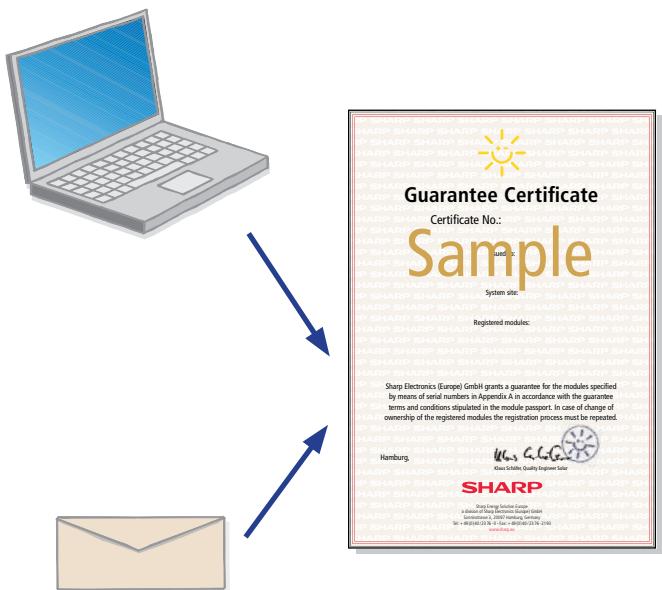
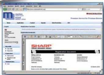
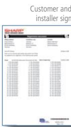
- You receive an official guarantee certificate on which all registered module serial numbers are listed
- No hassle enforcement of your product and performance guarantees
- You receive confirmation that your modules were supplied by Sharp Electronics (Europe) GmbH
- You can be certain that your products are genuine by verifying the serial numbers
- You receive proof of ownership, useful for insurance or in the case of theft, for example
- You help to clarify incidences of theft because the serial numbers can be marked as stolen in the registration portal
Easy, convenient, safe and vital
How to register your modules
Modules can be registered either by the plant operator or the installer/distributor/system integrator. To register the modules, you need the serial numbers or pallet numbers of your Sharp modules or the original Sharp order number and delivery advice note number.
For particularly fast, easy registration, we recommend convenient, secure access via www.brandaddedvalue.net.
If you do not have an internet connection, you can also register by post. However, in this case you must send the completed registration form (pages 9 and 10) to our service partner, Brand Added Value AG. After successful registration the plant operator then receives the Sharp guarantee certificate.
For questions regarding registration, please call the registration hotline, available in English and German: +49(0) 1805/2726371 (cost of call from outside Germany varies on country and telephone provider) or send an e-mail to: info@brandaddedvalue.net
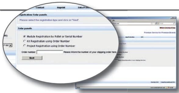
Your registration options
There are two ways to register the modules:
A. Provide the serial number or pallet number
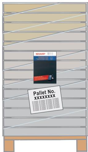
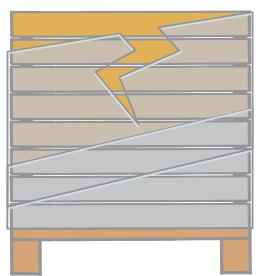
You can find the serial numbers on the front and rear sides of the modules and on the packaging. A complete pallet can be identified from the original foil wrapping which also contains the pallet number.
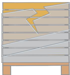
Complete pallets (36 modules) include an original Sharp advice note on which all 36 individual serial numbers are noted. In the case of complete pallets it suffices to enter the pallet number, as the system automatically allocates all corresponding module serial numbers based on the pallet number. In the case of partly filled pallets the module serial numbers must be entered individually.
B. Enter the original Sharp delivery advice note and order numbers
In the case of direct deliveries from Sharp, e.g. for large PV projects or the PV-KIT, it suffices to enter the original Sharp order and delivery advice note numbers to conveniently register all supplied modules. Please note: this registration procedure is only possible if the complete delivery can be allocated to a single PV plant or site.
Complete pallet
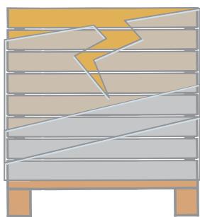
natural_image
Diagram of a wooden structure with broken and unbroken sections, no text or symbols presentPartly filled pallet
Registration by the plant operator
A. Enter the serial number or pallet number
Example: you receive three complete pallets, each containing 36 modules (total of 108 modules) and a partly filled pallet with a total of eight modules. To register all 116 modules, you only need the three pallet numbers of the complete pallets and the eight module serial numbers of the partly filled pallets.
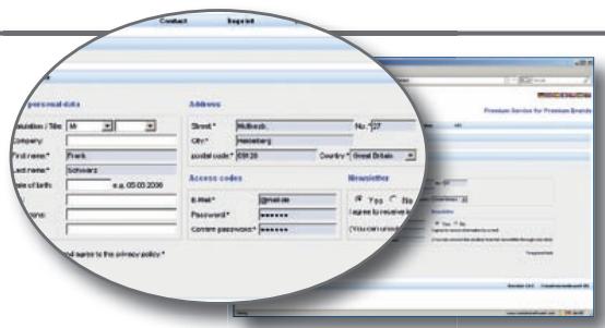
1. Create an account
To register, log in to www.brandaddedvalue.net as "Operator" and create an account with your personal details. To create an account, enter your personal details and click "save". Once you have successfully registered, you will receive an email to activate your user account. You can then commence registration.
2. Commissioning date and registration procedure
First select "Sharp Solar" as manufacturer and enter the commissioning date of your PV plant. To register by serial number or pallet number, please click the corresponding menu option. Next enter the name and address of your installer.
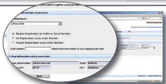
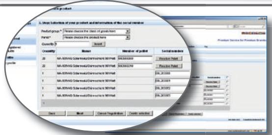
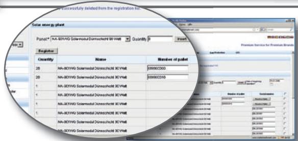
3. Product selection
Under product group, please select "Thin-film", followed by your module types and the quantity, and click "Insert". Then enter the pallet and/or serial number.
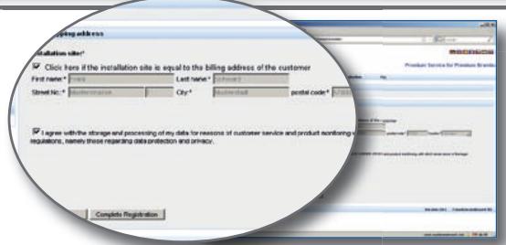
4. Plant location and completion
If the delivery address of your PV system is different from the invoice address, activate “Complete Registration” to complete the registration. After successful registration you will immediately receive a confirmation e-mail and the original guarantee certificate from Sharp by post.
B. Enter the original Sharp delivery advice note and order numbers
For convenient registration of complete deliveries, go to the website www.brandaddedvalue.net, select the manufacturer (Sharp Solar) "Kit Registration using Order Number" and "Project Registration using Order Number" menu options and follow the navigation sequence.
Registration by the installer, distributor or system integrator
A. Enter the serial number or pallet number
Example: you receive three complete pallets of 36 modules each (total of 108 modules) and a partly filled pallet with a total of eight modules. In this example, to register all 116 modules you need only the three pallet numbers of the complete pallets and the eight module serial numbers of the partly filled pallet.
1. Set up an account/select registration procedure
To register, log in to www.brandaddedvalue.net as "Dealer/Installer" and enter your login details, which you have received from Brand Added Value. To register, select the "Module Registration by Pallet or Serial Number" menu option.
2. Installer/customer data
If you did not install the equipment yourself, please enter details of the installer here. Then enter the invoice address of the plant operator and the installation location, if this is different to the invoice address; activate "click here for different location of PV system".

3. Modules and commissioning
Please select the module type and quantity, enter the 'start of operation' date and click "Insert". Then enter the pallet number and/or serial numbers.
4. Completion
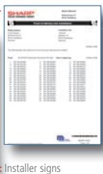
Click "Complete Registration" to complete the registration. Please print out the records as documentary proof and apply the signatures as confirmation. Subject to checking, the plant operator then receives its Sharp guarantee certificate by post.
B. Enter the original Sharp delivery advice note and order numbers
For convenient registration of complete deliveries, go to the website www.brandaddedvalue.net, select the manufacturer (Sharp Solar) "Kit Registration using Order Number" and "Project Registration using Order Number" menu options and follow the navigation sequence.
Here's how to register your modules in writing: by post or fax
You can also apply for guarantee services on your Sharp NA series thin-film modules by post or fax. Please send the completed registration form to: Brand Added Value AG, Moltkestrasse 27, 69120 Heidelberg, Germany, or fax to +49 (0) 62 21 - 61 60 47
Plant operator's personal data
| Company |
| Full name* |
| Post Code/City* |
| Telephone* (for registration questions only) |
| Title |
| Street, House No.* |
| Country* |
| Fax |
| Website (if available) |
Following successful registration, the guarantee certificate will be sent to the plant owner's stated address.
Location of installed PV equipment
| (if different from plant owner's personal data) |
| Street, House No.* |
| Country* |
| Post Code/City* |
| Contact person (where appropriate) |
First commissioning of PV equipment
| Date |
| Contact person |
| Post Code/City/Country* |
| Fax |
Details of installation company
| Company* |
| Street, House No* |
| Telephone* (for registration questions only) |
| Website (if available) |
| I agree to receive further information. Newsletters can be cancelled at any time. |

I agree to my data being stored and used in accordance with the provisions of data protection law.
Date and signature of plant operator
And now:
Your numbers please
Select module (Mark the relevant box and complete with the exact product designation)

NA series (1.05 m²), e.g. 95 W | 90 W
Product designation

NA series (1.42 m ^2 ), e.g. 142 W | 135 W | 128 W | 121 W
Product designation
Registration of complete pallets
Please enter the pallet numbers. On registering a complete pallet the corresponding module serial numbers will be automatically assigned.
Pallet number
| 01 | |
| 02 | |
| 03 | |
| 04 | |
| 05 |
Pallet number
| 06 | |
| 07 | |
| 08 | |
| 09 | |
| 10 |
Registration of partly filled pallets/individual modules
Please enter the individual serial numbers of the modules.
Serial number
| 01 | |
| 02 | |
| 03 | |
| 04 | |
| 05 | |
| 06 | |
| 07 | |
| 08 | |
| 09 |
Serial number
| 10 | |
| 11 | |
| 12 | |
| 13 | |
| 14 | |
| 15 | |
| 16 | |
| 17 | |
| 18 |
Registration of Sharp direct deliveries (Sharp PV-KIT/PV projects/site deliveries)
Enter the original Sharp order number and delivery advice note number for convenient registration of all installed modules of a PV-KIT, PV project or complete site delivery.
Delivery advice note number
Order number
Terms and conditions of guarantee for Sharp NA series photovoltaic modules
(valid for the above mentioned Sharp photovoltaic modules purchased since 01. August 2009)
IMPORTANT: Claims pursuant to these terms and conditions of guarantee can only be asserted if you or your installer has applied for registration for a guarantee on Sharp NA-series photovoltaic modules for your photovoltaic system (either via module passport – enclosed with the pallets – or via online registration to www.brandaddedvalue.net). The registration must be received by Sharp within a period of 12 weeks from initial commissioning of the photovoltaic system. In the event of failure to register within the 12-week period, no guarantee claims will be allowed.
Dear Sharp customer,
Each Sharp photovoltaic module purchased (later called the "product" or the "module") by you has been carefully manufactured and its functional ability tested in a final inspection. Should a photovoltaic module nevertheless at any time exhibit a defect in material and/or workmanship or a loss of output within the guarantee period, you can under the following conditions, and in addition to your statutory rights as a purchaser, claim against Sharp Electronics (Europe) GmbH under the product guarantee (A) or under the respective output guarantee (B I or B II) that is applicable to you.
This Certificate of Guarantee applies only to modules that Sharp Electronics (Europe) GmbH has placed on the European market or exported to Israel or Turkey. Should you be unsure in this respect, please contact your dealer.
A: Product Guarantee (applicable worldwide)
1) Scope of the product guarantee
If a manufacturing defect in material and workmanship (hereinafter 'defect') becomes apparent within 60 months from the date of purchase as set out below, you can claim under this product guarantee. This product guarantee is limited to the following components: frames, glass, cells, module cable including plug connectors, junction box and film.
This guarantee does not cover defects that are caused by improper handling, product changes, installation, operational errors or the actions of third parties.
The guarantee period of 60 months begins on the day on which the module was first purchased by you, the end user, from Sharp or from a dealer. In the event of a change of owner of the registered modules, new registration is required. Neither the new registration nor the execution of guarantee services will result in any extension of the original guarantee period.
2) Guarantee service
Sharp Electronics (Europe) GmbH shall fulfil its guarantee obligation by, at its option, either repairing the defective module free of charge or replacing it with a comparable module free of defects. If the type of module which is subject of the guarantee claim is not manufactured anymore, an actual and technically compatible standard type is delivered as substitute module. Any installation/dismantling costs that accrue shall not be borne by Sharp.
B I: Output guarantee (applicable in the EU, Albania, Bosnia and Herzegovina, Croatia, Iceland, Israel, Liechtenstein, Macedonia, Montenegro, Norway, Serbia, Switzerland and Turkey) The following output guarantee applies exclusively to output losses (i.e. degradation of the cells resulting in power loss) and not to any other defects in the modules.
1) Scope of the 25 years output guarantee
a) If, within a period of ten (10) years, the output of the module drops to less than 90% of the minimum output specified in the technical datasheet then Sharp will, at its own option, either compensate for the loss of output by supplying additional modules or by repairing or replacing the defective module, or reimburse the amount of the purchase price taking into consideration an annual depreciation of 4% of the original purchase price.
b) If, within a period of fifteen (15) years following the period under B I 1) a), the output of the module is less than 80% of the minimum output specified in the technical datasheet then Sharp will, at its own option, either compensate for the loss of output by supplying additional modules or by repairing or replacing the defective module, or reimburse the amount of the purchase price taking into consideration an annual depreciation of 4% of the original purchase price.
c) The guarantee period begins on the day on which the module was first purchased by end user from Sharp or from a dealer. In the event of a change of owner of the registered modules, new registration is required. Neither the new registration nor the execution of guarantee services will result in any extension of the original guarantee period.
d) Sharp is obliged to fulfil its output guarantee obligations only in case the examination of the module output has showed that the output losses of the module are based on a degradation/output loss of the cells. The examination of the module output is conducted under the following conditions: Cell temperature 25 degrees Celsius; 1000W / m^2 irradiance with AM-1.5 spectrum, on a system calibrated by Sharp (according to IEC 60904).
2) Limitation to the output guarantee
The output guarantee does not cover output losses that are caused by improper handling, operational errors or the actions of third parties. Sharp shall not bear the costs for dismantling, reinstallation and inspection by the customer nor shall it bear any other indirect costs. The output guarantee does not cover as well compensation for low energy yield or lost profits from sale of energy, which were caused by output losses of the module or the execution of guarantee services.
B II: Output guarantee (applicable outside of the EU, Albania, Bosnia and Herzegovina, Croatia, Iceland, Israel, Liechtenstein, Macedonia, Montenegro, Norway, Serbia, Switzerland and Turkey) The following output guarantee applies exclusively to output losses (i.e. degradation of the cells resulting in power loss) and not to any other defects in the modules.
1) Scope of the 10 years output guarantee
a) If, within a period of ten (10) years, the output of the module is less than 80 % of the minimum output specified in the technical datasheet then Sharp will, at its own option, either compensate for the loss of output by supplying additional modules or by repairing or replacing the defective module, or reimburse the amount of the purchase price taking into consideration an annual depreciation of 4 % of the original purchase price.
b) The guarantee period begins on the day on which the module was first purchased by the end user, from Sharp or from a dealer. In the event of a change of owner of the registered modules, new registration is required. Neither the new registration nor the execution of guarantee services will result in any extension of the original guarantee period.
c) Sharp is obliged to fulfil its output guarantee obligations only in case the examination of the module output has showed that the output losses of the module are based on a degradation/output loss of the cells. The examination of the module output is conducted under the following conditions: Cell temperature 25 degrees Celsius; 1000W / m^2 irradiance with AM-1.5 spectrum, on a system calibrated by Sharp (according to IEC 60904).
2) Limitations to the output guarantee
The output guarantee does not cover output losses that are caused by improper handling, operational errors or the actions of third parties. Sharp shall not bear the costs for dismantling, reinstallation and inspection by the customer nor shall it bear any other indirect costs. The output guarantee does not cover as well compensation for low energy yield or lost profits from sale of energy, which were caused by output losses of the module or the execution of guarantee services.
C: Exclusions
This product and output guarantee does not cover output loss and/or other defects that are caused by:
- defective system parts, supporting structures including fixing elements, system components such as inverters, generator connecting or string cables and string diodes;
- installation by persons who, in the reasonable opinion of Sharp, are not qualified or competent for the task;
- connecting the Sharp modules to a technically incompatible type of modules;
- incorrect system design, configuration and type of installation;
- incorrect wiring/installation work and incorrect handling during such work;
- failure to observe the applicable installation instruction (the applicable installation manual is attached to the module or will be provided to you by the dealer);
- operating the system under unsuitable ambient conditions or by using unsuitable methods that deviate from the product specifications, operating instructions or nameplate information;
- unsuitable maintenance and unsuitable tests, glass breaking due to external influences, flying objects or external loads as well as vandalism and theft;
- damage caused by external factors, such as dirt on the front glass, soiling, smoke, salt, chemicals, pollution or similar;
- paint or cleaning detergents applied to the modules;
- the use on mobile units such as vehicles and ships;
- event beyond our reasonable control (such as earthquakes, hurricanes, cyclones, volcano eruptions, flooding, lightning, indirect lighting strikes, snow damage, avalanches, frost damage, landslides, plagues of insects)
or other unforeseeable circumstances.
The output and product guarantee shall also be not applicable in the following cases:
- removal or manipulation of the nameplate on the back-side of the module;
- application or attachment of marks, signs, inscriptions or stickers on the foil on the back-side of the module without Sharp's express approval.
D: Claiming under the product or output guarantees
Claims pursuant to these terms and conditions of guarantee can only be asserted if you or your installer has applied for registration for a guarantee on Sharp NA-series photovoltaic modules for your photovoltaic system (either via module passport – enclosed with the pallets – or via online registration to www.brandaddedvalue.net). The registration must be received by Sharp within a period of 12 weeks from initial commissioning of the photovoltaic system. In the event of failure to register within the 12-week period, no guarantee claims will be allowed.
In order to bring a claim under the product or output guarantees, you will need to submit a written description of the defect and attach the registration number of the guaranty certificate, the invoice which provides the purchase date, the model description and the serial number of the module (see nameplate). Claims should be sent to:
Sharp Electronics (Europe) GmbH
Solar Business Group, codeword: guarantee, Sonninstrasse 3
D-20097 Hamburg, Germany
Claims in regard of the product or output failure of the module according to this product or output guarantee will be time barred within 6 months after discovery of the product or output failure.
No returns of modules, defective or otherwise, will be accepted without prior written authorisation of Sharp Electronics (Europe) GmbH.
E: Guarantor
Sharp Electronics (Europe) GmbH, Sonninstrasse 3, D-20097 Hamburg, Germany.
www.sharp.eu
F: Choice of law, place of jurisdiction
1) Choice of law: This guarantee is governed by German law. International private law is excluded. This does not apply to consumers, as far as this guarantee falls below mandatory national consumer protection regulations. In this case the law which is more beneficial for the consumer shall apply.
2) Place of jurisdiction: Hamburg (Germany) shall be the exclusive place of jurisdiction for merchants and legal entities of public law.
natural_image
Black and white photo of a blue ARP tablet device with a grid of solar panels, placed on top of a partially open base (no visible text or symbols)natural_image
Diagram of a wooden structure with broken and partially collapsed panels, no text or symbols presentangebrochene Palette
natural_image
Side profile of a person standing on a rooftop with solar panels, no visible text or symbolsnatural_image
Close-up of a black electronic device with blue LED screen, partially placed on a blue surface (no visible text or symbols)palette complète
natural_image
Diagram of a wooden structure with broken panels and supports (no text or symbols)palette partielle
4. Validation
Terms and conditions of guarantee for Sharp NA series photovoltaic modules
(valid for the above mentioned Sharp photovoltaic modules purchased since 01. August 2009)
IMPORTANT: Claims pursuant to these terms and conditions of guarantee can only be asserted if you or your installer has applied for registration for a guarantee on Sharp NA-series photovoltaic modules for your photovoltaic system (either via module passport – enclosed with the pallets – or via online registration to www.brandaddedvalue.net). The registration must be received by Sharp within a period of 12 weeks from initial commissioning of the photovoltaic system. In the event of failure to register within the 12-week period, no guarantee claims will be allowed.
Dear Sharp customer,
Each Sharp photovoltaic module purchased (later called the "product" or the "module") by you has been carefully manufactured and its functional ability tested in a final inspection. Should a photovoltaic module nevertheless at any time exhibit a defect in material and/or workmanship or a loss of output within the guarantee period, you can under the following conditions, and in addition to your statutory rights as a purchaser, claim against Sharp Electronics (Europe) GmbH under the product guarantee (A) or under the respective output guarantee (B I or B II) that is applicable to you.
This Certificate of Guarantee applies only to modules that Sharp Electronics (Europe) GmbH has placed on the European market or exported to Israel or Turkey. Should you be unsure in this respect, please contact your dealer.
A: Product Guarantee (applicable worldwide)
1) Scope of the product guarantee
If a manufacturing defect in material and workmanship (hereinafter 'defect') becomes apparent within 60 months from the date of purchase as set out below, you can claim under this product guarantee. This product guarantee is limited to the following components: frames, glass, cells, module cable including plug connectors, junction box and film.
This guarantee does not cover defects that are caused by improper handling, product changes, installation, operational errors or the actions of third parties.
The guarantee period of 60 months begins on the day on which the module was first purchased by you, the end user, from Sharp or from a dealer. In the event of a change of owner of the registered modules, new registration is required. Neither the new registration nor the execution of guarantee services will result in any extension of the original guarantee period.
2) Guarantee service
Sharp Electronics (Europe) GmbH shall fulfil its guarantee obligation by, at its option, either repairing the defective module free of charge or replacing it with a comparable module free of defects. If the type of module which is subject of the guarantee claim is not manufactured anymore, an actual and technically compatible standard type is delivered as substitute module. Any installation/dismantling costs that accrue shall not be borne by Sharp.
B I: Output guarantee (applicable in the EU, Albania, Bosnia and Herzegovina, Croatia, Iceland, Israel, Liechtenstein, Macedonia, Montenegro, Norway, Serbia, Switzerland and Turkey) The following output guarantee applies exclusively to output losses (i.e. degradation of the cells resulting in power loss) and not to any other defects in the modules.
1) Scope of the 25 years output guarantee
a) If, within a period of ten (10) years, the output of the module drops to less than 90% of the minimum output specified in the technical datasheet then Sharp will, at its own option, either compensate for the loss of output by supplying additional modules or by repairing or replacing the defective module, or reimburse the amount of the purchase price taking into consideration an annual depreciation of 4% of the original purchase price.
b) If, within a period of fifteen (15) years following the period under B I 1) a), the output of the module is less than 80% of the minimum output specified in the technical datasheet then Sharp will, at its own option, either compensate for the loss of output by supplying additional modules or by repairing or replacing the defective module, or reimburse the amount of the purchase price taking into consideration an annual depreciation of 4% of the original purchase price.
c) The guarantee period begins on the day on which the module was first purchased by end user from Sharp or from a dealer. In the event of a change of owner of the registered modules, new registration is required. Neither the new registration nor the execution of guarantee services will result in any extension of the original guarantee period.
d) Sharp is obliged to fulfil its output guarantee obligations only in case the examination of the module output has showed that the output losses of the module are based on a degradation/output loss of the cells. The examination of the module output is conducted under the following conditions: Cell temperature 25 degrees Celsius; 1000W / m^2 irradiance with AM-1.5 spectrum, on a system calibrated by Sharp (according to IEC 60904).
2) Limitation to the output guarantee
The output guarantee does not cover output losses that are caused by improper handling, operational errors or the actions of third parties. Sharp shall not bear the costs for dismantling, reinstallation and inspection by the customer nor shall it bear any other indirect costs. The output guarantee does not cover as well compensation for low energy yield or lost profits from sale of energy, which were caused by output losses of the module or the execution of guarantee services.
B II: Output guarantee (applicable outside of the EU, Albania, Bosnia and Herzegovina, Croatia, Iceland, Israel, Liechtenstein, Macedonia, Montenegro, Norway, Serbia, Switzerland and Turkey) The following output guarantee applies exclusively to output losses (i.e. degradation of the cells resulting in power loss) and not to any other defects in the modules.
1) Scope of the 10 years output guarantee
a) If, within a period of ten (10) years, the output of the module is less than 80 % of the minimum output specified in the technical datasheet then Sharp will, at its own option, either compensate for the loss of output by supplying additional modules or by repairing or replacing the defective module, or reimburse the amount of the purchase price taking into consideration an annual depreciation of 4 % of the original purchase price.
b) The guarantee period begins on the day on which the module was first purchased by the end user, from Sharp or from a dealer. In the event of a change of owner of the registered modules, new registration is required. Neither the new registration nor the execution of guarantee services will result in any extension of the original guarantee period.
c) Sharp is obliged to fulfil its output guarantee obligations only in case the examination of the module output has showed that the output losses of the module are based on a degradation/output loss of the cells. The examination of the module output is conducted under the following conditions: Cell temperature 25 degrees Celsius; 1000W / m^2 irradiance with AM-1.5 spectrum, on a system calibrated by Sharp (according to IEC 60904).
2) Limitations to the output guarantee
The output guarantee does not cover output losses that are caused by improper handling, operational errors or the actions of third parties. Sharp shall not bear the costs for dismantling, reinstallation and inspection by the customer nor shall it bear any other indirect costs. The output guarantee does not cover as well compensation for low energy yield or lost profits from sale of energy, which were caused by output losses of the module or the execution of guarantee services.
C: Exclusions
This product and output guarantee does not cover output loss and/or other defects that are caused by:
- defective system parts, supporting structures including fixing elements, system components such as inverters, generator connecting or string cables and string diodes;
- installation by persons who, in the reasonable opinion of Sharp, are not qualified or competent for the task;
- connecting the Sharp modules to a technically incompatible type of modules;
- incorrect system design, configuration and type of installation;
- incorrect wiring/installation work and incorrect handling during such work;
- failure to observe the applicable installation instruction (the applicable installation manual is attached to the module or will be provided to you by the dealer);
- operating the system under unsuitable ambient conditions or by using unsuitable methods that deviate from the product specifications, operating instructions or nameplate information;
- unsuitable maintenance and unsuitable tests, glass breaking due to external influences, flying objects or external loads as well as vandalism and theft;
- damage caused by external factors, such as dirt on the front glass, soiling, smoke, salt, chemicals, pollution or similar;
- paint or cleaning detergents applied to the modules;
- the use on mobile units such as vehicles and ships;
- event beyond our reasonable control (such as earthquakes, hurricanes, cyclones, volcano eruptions, flooding, lightning, indirect lighting strikes, snow damage, avalanches, frost damage, landslides, plagues of insects)
or other unforeseeable circumstances.
The output and product guarantee shall also be not applicable in the following cases:
- removal or manipulation of the nameplate on the back-side of the module;
- application or attachment of marks, signs, inscriptions or stickers on the foil on the back-side of the module without Sharp's express approval.
D: Claiming under the product or output guarantees
Claims pursuant to these terms and conditions of guarantee can only be asserted if you or your installer has applied for registration for a guarantee on Sharp NA-series photovoltaic modules for your photovoltaic system (either via module passport – enclosed with the pallets – or via online registration to www.brandaddedvalue.net). The registration must be received by Sharp within a period of 12 weeks from initial commissioning of the photovoltaic system. In the event of failure to register within the 12-week period, no guarantee claims will be allowed.
In order to bring a claim under the product or output guarantees, you will need to submit a written description of the defect and attach the registration number of the guaranty certificate, the invoice which provides the purchase date, the model description and the serial number of the module (see nameplate). Claims should be sent to:
Sharp Electronics (Europe) GmbH
Solar Business Group, codeword: guarantee, Sonninstrasse 3
D-20097 Hamburg, Germany
Claims in regard of the product or output failure of the module according to this product or output guarantee will be time barred within 6 months after discovery of the product or output failure.
No returns of modules, defective or otherwise, will be accepted without prior written authorisation of Sharp Electronics (Europe) GmbH.
E: Guarantor
Sharp Electronics (Europe) GmbH, Sonninstrasse 3, D-20097 Hamburg, Germany.
www.sharp.eu
F: Choice of law, place of jurisdiction
1) Choice of law: This guarantee is governed by German law. International private law is excluded. This does not apply to consumers, as far as this guarantee falls below mandatory national consumer protection regulations. In this case the law which is more beneficial for the consumer shall apply.
2) Place of jurisdiction: Hamburg (Germany) shall be the exclusive place of jurisdiction for merchants and legal entities of public law.
Importante: Tenga presente ...
natural_image
Black and white photo of a blue ARP device with a grid of solar panels, placed on top of a blue cover (no visible text or symbols)paleta completa
natural_image
Diagram of a wooden structure with diagonal bracing and horizontal supports (no text or symbols)paleta incompleta
| Year Ended December 31, | ||
| 2018 | 2017 | |
| Revenues | 1,465 | 1,395 |
| Costs and expenses | (1,048) | (1,013) |
| Net income | 1,465 | 1,395 |
natural_image
Side profile of a person standing on a rooftop with solar panels, no visible text or symbolsGeneral installation manual
PLEASE READ THIS MANUAL CAREFULLY BEFORE INSTALLING OR USING THE MODULES. PLEASE PASS ALONG THE ATTACHED USER MANUAL TO YOUR CUSTOMER.
Legally binding is only the actual, original and product specific manual which is included in the carton box.
1. INTRODUCTION
This Installation Manual contains essential information for the electrical and mechanical installation that you must know before installing Sharp PV modules. This also contains safety information you need to be familiar with. All the information described in this manual are the intellectual property of Sharp and based on the technologies and experiences that have been acquired and accumulated in the long history of Sharp. This document does not constitute a guaranty, expressed or implied. Sharp does not assume responsibility and expressly disclaims liability for loss, damage, or expense arising out of or in any way connected with installation, operation, use or maintenance of the PV modules. No responsibility is assumed by Sharp for any infringement of patents or other rights of third parties that may result from use of PV module. Sharp reserves the right to make changes to the product, specifications or installation manual without prior notice.
2. GENERAL INFORMATION (INCLUDING WARNING AND SAFETY)
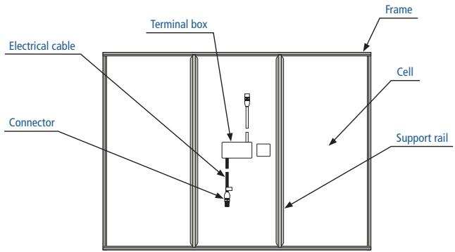
The installation of PV modules requires a great degree of skill and should only be performed by a qualified licensed professional, including licensed contractors and licensed electricians. Please be aware that there is a serious risk of various types of injury occurring during the installation including the risk of electric shock. All Sharp PV modules are equipped with a permanently attached junction terminal box that will accept variety of wiring applications or with a special cable assembly for ease of installation, and they do not require special assembly.
- PV modules are heavy. Handle with care.
- Before you attempt to install, wire, operate and maintain the PV module, please make sure that you completely understand the information described in this installation manual.
- Contact with electrically active parts of a PV module such as terminals can result in burns, sparks and lethal shock whether the PV modules are connected or not.
- PV modules produce electricity when the sufficient sunlight or other sources illuminate the module surface. When the modules are connected in series, voltage is cumulative. When the modules are connected in parallel, current is cumulative.
As a result, a large-scale PV system can produce high voltage and current which could present an increased hazard and may cause serious injury or death. - Do not connect the PV modules directly to the loads such as motor since the variation of the output power depending on the solar irradiation causes damage for the connected motor.
1: In the case of a brushless motor, the lock function becomes active and the hall IC is most likely to be damaged.
2: In the case of a brush type motor, the coil is most likely to be damaged.
- Consult local codes and other applicable laws concerning required permits on regulations concerning installation and inspection requirements.
- Before installing a PV module, contact appropriate authorities to determine permit, installation and inspection requirements that should be followed.
- Install PV modules and ground frames in accordance with applicable rules and regulations.
- PV modules should be installed and maintained by qualified personnel. Only installer/servicer personnel should have access to the PV module installation site.
- No matter where the PV modules are installed, either roof mounted construction or any other type of structures above the ground, appropriate safety practices should be followed and required safety equipment should be used in order to avoid possible safety hazards. Note that the installation of some PV modules on roofs may require the addition of fireproofing, depending on local building/fire codes.
- In the case that the PV modules are non-integral type, the module is to be mounted over a fire resistant roof.
- Please use PV modules, which have the same electrical characteristics, within a string.
- Follow all safety precautions of other components used in the system.
- In order to avoid a risk of injury or electrical shock, do not allow anyone to approach the PV module if the person has little knowledge on PV module or on the measures that should be taken when PV modules are damaged.
- Do not shade portions of the PV module surface from the sunlight for a long time. The shaded cell may become hot (hot spot phenomenon) which results in solder joints peeling off.
- Do not clean the glass surface with chemicals. Do not let water stay on the glass surface of PV modules for a long time. This creates a risk of white efflorescence (glass disease) which may result in the deterioration of energy generation.
- Do not install the PV module horizontally. It may cause dirt or white efflorescence (glass disease) due to water
- Do not cover the water drain holes of the frame. There is a risk of frost damage when the frame is filled with water cumulation.
- When sliding snow load has to be considered, an appropriate measure has to be taken so that PV module frames on lower edge of PV modules will not be damaged.
General installation manual
- Do not expose PV module to sunlight concentrated with mirrors, lenses or similar means.
- Turn off inverters and circuit breakers immediately, should a problem occur.
- In case the glass surface of a PV module is broken, wear goggles and tape the glass to keep the broken pieces in place.
- A defective PV module may generate power even if it is removed from the system. It may be dangerous to handle the PV module while exposed to sunlight. Place a defective PV module in a carton so PV cells are completely shaded.
- In case of series connection, the maximum open circuit voltage must not be greater than the specified maximum system voltage. The voltage is proportional to the number of series. In case of parallel connection, please be sure to take proper measure (e.g. fuse for protection of module and cable from over current, and/or blocking diode for prevention of unbalanced strings voltage) to block the reverse current flow. The current may easily flow in a reverse direction.
< HANDLING SAFETY >
- Do not cause an excessive load on the surface of PV module or twist the frame. The glass surface can easily break.
- Do not stand or step on the PV module. The surface glass of PV module is slippery.
- Do not hit or put excessive load on the glass or back sheet. The PV cell is very thin and can be easily broken.
- Do not scratch or hit at the back sheet. The back sheet is vulnerable.
- Do not hit on the terminal box or do not pull the cables. The terminal box can crack and break.
- Never touch terminal box or the end of output cables with bare hands when the PV module is irradiated. Cover the surface of PV module with cloth or other suitable sufficiently opaque material to isolate the PV module from incident light and handle the wires with rubber-gloved hands to avoid electric shock.
- Do not scratch the output cable or bend it with force. The insulation of output cable can break and may result in electricity leakage or shock.
- Do not pull the output cable excessively. The output cable may unplug and cause electricity leakage or shock.
- Do not drill holes in the frame. It may compromise the frame strength and cause corrosion of the frame.
- Do not scratch the insulation coating of the frame (except for grounding connection). It may cause corrosion of the frame or compromise the framework strength.
- Do not loosen or remove the screws of the PV module. It may compromise the joint strength of PV module and cause corrosion.
- Do not touch the PV module with bare hands. The frame of PV module has sharp edges and may cause injury.
- Do not drop PV module or allow objects to fall down on the PV module.
- Do not try artificially to concentrate sunlight on the PV module.
- Do not grab the PV module at only one side. The frame may bend. Grab the PV module at two sides facing each other.
- Always wear protective head gear, insulating gloves and safety shoes (with rubber soles).
- Keep the PV module packed in the carton until installation.
- Do not touch the PV module unnecessarily during installation. The glass surface and the frames get hot. There is a risk of burn, or you may collapse because of electric shock.
- Do not work under rain, snow or windy conditions.
- Use insulated tools.
- Do not use wet tools.
- Do not drop tools or hard objects on PV modules
- When installing PV modules far above ground, do not drop any object (e.g., PV module or tools).
- Make sure flammable gases are not generated near the installation site.
- Completely cover the PV module surface with an opaque material during PV module installation and wiring.
- Plug in the connector tight and ensure the wiring work.
- Due to the risk of electrical shock, do not perform any work if the terminals of PV module are wet.
- Do not touch the terminal box and the end of output cables the cable ends (connectors) with bare hands during installation or under sunlight, regardless of whether the PV module is connected to or disconnected from the system.
- Do not unplug the connector if the system circuit is connected to a load.
- Do not stomp on the glass at work. There is a risk of injury or electric shock if glass is broken.
- Do not work alone (always work as a team of 2 or more people).
- Wear a safety belt if working far above the ground.
- Do not wear metallic jewelry which can cause electric shock during installation.
General installation manual
- Do not damage the back sheet of PV modules when fastening the PV modules to a support by bolts.
- Do not damage the surrounding PV modules or mounting structure when replacing a PV module.
- Bind cables by the insulation locks. Drooping down of cables from the terminal box could possibly cause various problems such as animal biting, electricity leakage in puddle.
- Take proper measures for preventing the laminate (consisted of resin, cells, glass, back sheet, etc.) from dropping out of the frame in case the glass is broken.
- Cables shall be located so that they will not be exposed to direct sunlight after installation to prevent degradation of cables.
-
Do not put anything (e.g. tools, clothes, etc.) on the modules during their installation, because shaded part may be heated.
-
COMPONENTS (from backside view)
4. SITE SELECTION
In most applications, the PV modules should be installed in a location where there is no shading throughout the year. In the Northern Hemisphere, the PV modules should typically face south, and in the Southern Hemisphere, the PV modules should typically face north. Please make sure that there are no obstructions in the surroundings of the site of installation. Take proper steps in order to maintain reliability and safety, in case the PV modules are used in areas such as: Heavy snow areas/Extremely cold areas/Strong wind areas/Installations over, or near, water/Areas where installations are prone to salt water damage(*)/Small islands or desert areas.
(*) If you are planning to use the PV modules where salt water damage may be possible, please consult with Sharp local agent first to determine an appropriate installation method, or to determine whether the installation is possible.
5. TILT ANGLE
The tilt angle of the PV module is measured between the PV module and a horizontal ground surface. The PV module generates the maximum output power when it faces the sun directly. For the standalone systems with a battery where the PV modules are attached to a permanent structure, the tilt angle of the PV modules should be determined to optimize the performance when the sunlight is the scarcest. In general, if the electric power generation is adequate when the sunlight is the scarcest, then the angle chosen should be adequate during the rest of the year. For grid-connected installations where the PV modules are attached to a permanent structure, it is recommended to tilt the PV module at the angle equal to the latitude of the installation site so that the power generation from the PV module will be optimum throughout the year.
6. WIRING
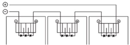
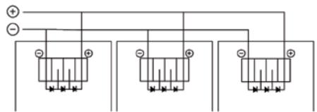
To ensure proper system operation and to maintain your guaranty, observe the correct cable connection polarity (Fig. 1 & 2) when connecting the modules to a battery or to other modules. If not connected correctly, the bypass diode could be destroyed. PV modules can be wired in series to increase voltage. Connect wires from the positive terminal of one module to the negative terminal of the next module. Fig. 1 shows modules connected in series. Connect PV modules in parallel to increase current. Connect wires from the positive terminal of one module to the positive terminal on the next module. Fig. 2 shows modules connected.
FIGURE 1: SERIES FOR MORE VOLTAGE
flowchart
graph TD
    A["+"] --> B["Terminal 1"]
    C["-"] --> D["Terminal 2"]
    E["Terminal 3"] --> F["Terminal 4"]
FIGURE 2: PARALLEL FOR MORE CURRENT
General installation manual
7. INSTALLATION
Refer to installation manual of PV module.
8. ELECTRICAL RATINGS
Refer to installation manual of PV module.
9. GROUNDING
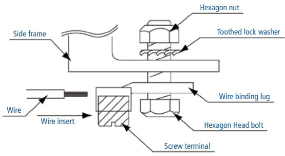
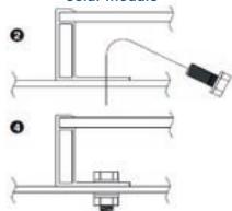
The frame grounding is considered within the local requirement and regulation at the site of installation. When needed this grounding, please refer to below example of connection. Please be careful in arranging the system ground so that the removal of one module from the circuit will not interrupt the grounding of any other modules. The modules should be grounded to the same electrical point as described below. Each PV module has a hole on the side frame for either bolt, nut and washer grounding the module to the frame, a ground lug fastened by bolt or screw, or appropriate screw (hardware not provided). An example of acceptable ground connection using a bolt, nut and washer retaining a ground lug is shown in Fig. 3. In a connection of this type, the hardware (such as a toothed locked washer/star washer) must score the frame surface to make positive electrical contact with the frame. The ground wire must be considered within the requirement of local and regulation at the site of installation.
FIGURE 3: EXAMPLE OF GROUND CONNECTION
10. MOUNTING
Please make sure that all the information described in the installation manual is still valid and proper for your installation. The mounting method has been verified by Sharp and NOT CERTIFIED by a third party organization.
Although Sharp does not specify or warrant frame clips or clamps, using frame clips (not provided) or clamps (not provided) is also possible when they are designed for PV modules and with minimum dimensions on the sides of the module in accordance with the instructions and drawings provided. If using frame clips or clamps, the modules should be fixed rigidly and there shall be no damage to the modules by deforming mounting structure against design load. The Sharp module guaranty may be void if customer-selected frame clips which are improper or inadequate with respect to the module properties (including strength or material) or installation. Note that if metal clips are used, there must be a path to ground from the clips, (for instance, using star washers in the clip hardware set).
Please review the descriptions and drawings carefully; not mounting the modules according to one of these methods may void your guaranty. Support structures that PV modules are mounted on should be rigid. Sharp PV modules are designed to secure their electric performance under the condition that they are mounted on rigid support structures. Deformation of support structure may damage PV module with its electric performance.
11. MAINTENANCE
The modules are designed for long life and require very little maintenance. If the angle of the PV module is 5 degrees or more, normal rainfall is sufficient to keep the module glass surface clean under most weather conditions. If dirt build-up becomes excessive, clean the glass surface only with a soft cloth using water. If cleaning the back of the module is required, take utmost care not to damage the back side materials. In order to ensure the operation of the system, please check the connection of wiring and the state of the jacket of wires every now and then.
Installation manual – photovoltaic modules
NA Series (1.05 m²)
1. INSTALLATION
The mounting method has been verified by Sharp and NOT CERTIFIED by a third party organization. Please review the descriptions and drawings carefully; not mounting the modules according to one of these methods may void your warranty. These mounting methods are designed to allow module loading of 2,400 Pa.
Mounting using frame bolt holes (Fig. 1 & 3)
The modules may be fastened to a support using the bolt holes in the bottom of the frame at location "C", as shown in Fig. 1 (back view of the module) and Fig. 3 (mounting detail). The module should be fastened with six (6) M8 (5/16") bolts. Take care during installation to not block the drain holes "D" shown in Fig. 1.
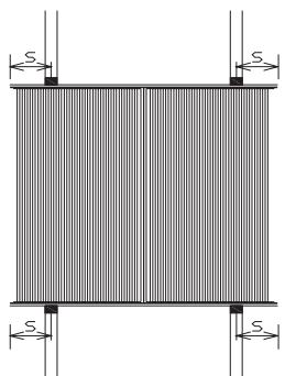
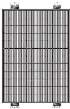
Mounting Using Clips on Long Edge of Module: Long Edge Perpendicular to Array Rails (Fig. 4)
The modules may also be mounted using clips on the long sides of the module when the array rails are perpendicular to the long sides, as shown in Fig. 4. The clip centerlines must be between 3.2" (81 mm) and 11.1" (282 mm) from the ends of the module. Note that the mounting clips should meet the minimum dimensions (catch width of 0.2" (5 mm) and length of 1.2" (30 mm)) shown in Fig. 2. The array rails must support the bottom of the modules and must be continuous pieces (no breaks in the rail). Take care during installation to not block the drain holes "D" shown in Fig. 1.
Installation direction
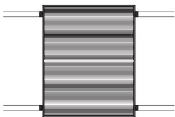
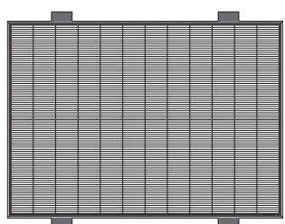
PV cells of our thin-film PV module have a striped line pattern. So, please avoid shade from covering the striped line pattern. According to the above-mentioned claim, it is generally recommended that the PV modules are installed with the stripe lines in the vertical position as shown in Fig. 4. The installation with the striped line in a horizontal position as shown in Fig. 5 is not recommended because snow covering, dust and dirt may reduce the power output of PV module. Moreover, in rare cases, permanent damage to an output characteristic of PV modules may occur, or an exfoliation of thin-film silicon may appear if the PV modules are installed with horizontal position.
Notes: In rare cases, the recommended direction is changed from vertical position to horizontal position. For example, in case that the module is shaded along a vertical line, a recommended direction is horizontal position.
FIGURE 1
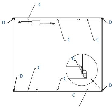
FIGURE 2
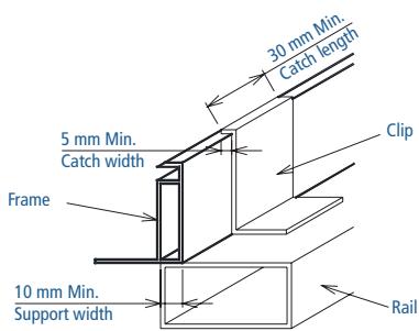
FIGURE 3
Solar module
natural_image
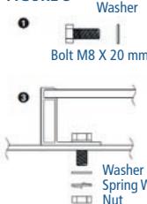
Technical line drawing of a mechanical assembly with two views (labeled ① and ②), no text or symbols present.For your reference, please use the washer specified as below for the minimum requirement:
1) Spring washer
2) Washer
Material stainless steel
Material stainless steel
Diameter M8 8.2/15.4 mm
Diameter M8 8.5/15.5 mm
Thickness 2 mm (reference value)
Thickness 1.6 mm (reference value)
FIGURE 4
natural_image
Pure structural diagram of a rectangular frame with vertical supports and horizontal slats, no text or symbols present.FIGURE 5
natural_image
Pure diagram of a rectangular block with horizontal lines and two vertical connectors at the top (no text or symbols)FIGURE 6
Caution: The mounting methods shown in Fig. 6 are prohibited.
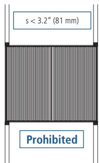
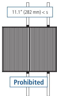
3.2" (81 mm) < s < 11.1" (282 mm)
Installation manual – photovoltaic modules
NA Series (1.05 m²)
2. ELECTRICAL INSTALLATION INSTRUCTION
Cable characteristics
Size: 2.5 mm ^2 Type: CE cable Temperature rating of conductor: -40\~90 °C
Module configuration
# Maximum series configuration: please refer to Table 1 (This value is calculated under the condition of V_oc at -40 °C.)
# Maximum parallel configuration: (Parallel connection of each string must be conducted with following two options. Any other parallel connections are prohibited.)
a) Case of using diodes: 1 diode per maximum 2 parallel strings (Connect a diode for every string or every 2 parallel strings for protection of module from reverse current overload.)
b) Case of using the fuses: 1 fuse per every string (Connect a fuse for every single string for protection of module from reverse current over load.)
Inverter
An inverter shall be used which can set DC electrical potential to positive voltage to ground. To do this, for example, set the DC negative pole of the inverter to ground.
3. WARNING
Do not stand or step on the PV module (frame, glass, film and terminal box).
4. ELECTRICAL OUTPUT
Rated electrical characteristics are within ±10 percent of the indicated values of I_sc , V_oc , and P_max under STC (standard test conditions)
(irradiance of 1,000 W/m ^2 , AM 1.5 spectrum and a cell temperature of 25°C (77°F)). The warranty conditions are specified elsewhere in this manual.
Table 1. Electrical characteristics (at STC)
| Model name | Type(*1) | Initial/stable (nominal) | Maximum power (Pmax) | Open-circuit voltage (Voc) | Short-circuit current (Isc) | Voltage at point of max. power (Vmpp) | Current at point of max. power (Impp) | Maximum system voltage | Over-current protection | Application class | Maximum series configuration(*2) |
| NA-851WQ | Tandem | Initial | 100 W | 65.0 V | 2.20 A | 52.0 V | 1.92 A | 600 V | 4 A | A | 7 (*3) |
| Stable (nominal) | 85 W | 63.8 V | 2.11 A | 49.0 V | 1.74 A | ||||||
| NA-901WQ | Tandem | Initial | 105.9 W | 66.6 V | 2.20 A | 53.5 V | 1.98 A | 600 V | 4 A | A | 7 |
| Stable (nominal) | 90 W | 65.2 V | 2.11 A | 49.3 V | 1.83 A | ||||||
| NA-953WQ | Tandem | Initial | 111.8 W | 66.3 V | 2.37 A | 52.7 V | 2.12 A | 600 V | 4 A | A | 7 |
| Stable (nominal) | 95 W | 65.3 V | 2.30 A | 48.0 V | 1.98 A | ||||||
| NA-F090B5 | Tandem | Initial | 105.9 W | 63.8 V | 2.42 A | 50.5 V | 2.10 A | 1,000 V | 4 A | A | 12 |
| Stable (nominal) | 90 W | 62.8 V | 2.34 A | 47.7 V | 1.89 A | ||||||
| NA-F095B5 | Tandem | Initial | 111.8 W | 64.8 V | 2.43 A | 52.0 V | 2.15 A | 1,000 V | 4 A | A | 12 |
| Stable (nominal) | 95 W | 63.8 V | 2.37 A | 47.5 V | 2.00 A |
(*1) Tandem: amorphous silicon/microcrystalline silicon tandem structure cell
(*2) The maximum series number of modules depends on the local conditions. This value is calculated under the condition of V_oc at -40°C.
(*3) Maximum series configuration is 8 if the module temperature is greater than -10°C.
System design should consider both initial values and nominal values.
Under normal conditions, a photovoltaic module is likely to experience conditions that produce more current and/or voltage than reported at Standard Test Conditions. Accordingly, the values of I_sc and V_oc marked on this module should be multiplied by a factor of 1.25 when determining component voltage ratings, conductor capacities, fuse sizes and size of controls connected to the module output.
Installation manual – photovoltaic modules
NA Series (1.42 m²)
1. INSTALLATION
The mounting method has been verified by Sharp and NOT CERTIFIED by a third party organization. Please review the descriptions and drawings carefully; not mounting the modules according to this method may void your guaranty. This mounting method is designed to allow module loading of 2,400 Pa/long side mounting and 2,000 Pa/short side mounting (Test passed in accordance with IEC61646, applying loads up to 2,400 Pa).
Mounting Using Long side mounting of module: Long Edge (Fig. 1)
The modules may be mounted using clips on the long sides of the module when the array rails are perpendicular to the long sides, as shown in Fig. 1. The clip centerlines must be between 6.2" (157.5 mm) and 16.44" (417.5 mm) from the ends of the module. Note that the mounting clips should meet the minimum dimensions (catch width of 0.2" (5 mm) and length of 1.2" (30 mm)) shown in Fig. 3. The array rails must support the bottom of the modules and must be continuous pieces (no breaks in the rail).
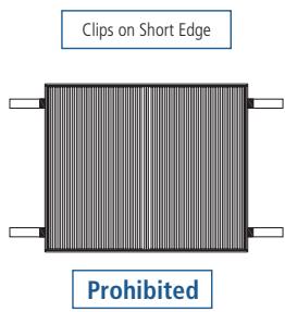
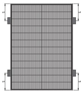
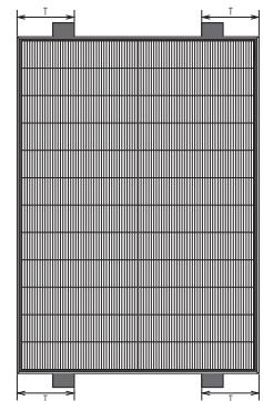
Mounting Using Short side mounting of Module: Short Edge (Fig. 2)
The modules may be mounted using clips on the short sides of the module when the array rails are parallel to the short sides, as shown in Fig. 2. The clip centerlines must be between 3.94" (100.0 mm) and 7.87" (200.0 mm) from the ends of the module. Note that the mounting clips should meet the minimum dimensions (catch width of 0.2" (5 mm) and length of 1.2" (30 mm)) shown in Fig. 3. The array rails must support the bottom of the modules and must be continuous pieces (no breaks in the rail).
Installation direction
PV cells of our thin-film PV module have a stripe line pattern. So, please avoid shade from covering the striped line pattern.
According to the above-mentioned claim, the PV modules must be installed with the stripe lines in the vertical position as shown in Fig. 1. The installation with the striped line in a horizontal position as shown in Fig. 4 is prohibited. Permanent damage to an output characteristic of PV modules may occur, or a corrosion of thin-film silicon may appear if the PV modules are installed with horizontal position and are covered by snow, dust and dirt.
FIGURE 1
natural_image
Pure geometric diagram of a rectangular grid with side markers and dimension 's' (no text or symbols)6.2" (157.5 mm) < s < 16.44" (417.5 mm)
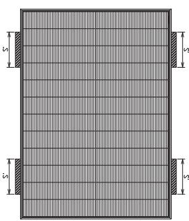
natural_image
Pure geometric diagram of a rectangular grid with side length labels (no text or symbols)s' = 10.24" (260 mm)
(Maximum load 2,400 Pa)
(In case of clips on long side frame of module)
FIGURE 2
natural_image
Pure grid pattern with no text, numbers, or symbols3.94" (100.0 mm) < T < 9.84" (250.0 mm)
natural_image
Pure grid pattern with no text, numbers, or symbolsT^ = 5.9^ (150.0 mm)
(Maximum load 2,000 Pa)
(In case of clips on short side frame of module)
Permissible clamp area
Clip
FIGURE 3
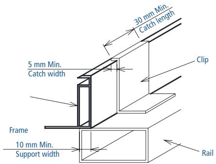
FIGURE 4
natural_image
Grid-patterned rectangular panel with side supports (no text or symbols)Prohibited
Installation manual – photovoltaic modules
NA Series (1.42 m²)
2. ELECTRICAL INSTALLATION INSTRUCTION
Cable characteristics
Size: 2.5 mm ^4 Type: CE cable
Temperature rating of conductor: -40\~90 °C
Module configuration
Maximum series configuration: please refer to Table 1 (This value is calculated under the condition of V_oc at -40^ .)
Maximum parallel configuration: (Parallel connection of each string shall be conducted with following two options. Any other parallel connections are prohibited.)
a) Case of using the diodes: 1 diode per maximum 2 parallel strings (Connect a diode or more in series for every string or every 2 parallel strings for protection of module from reverse current over load.)
b) Case of using the fuses: 1 fuse per every string (Connect a fuse for every single string for protection of module from reverse current over load.)
Inverter requirement
All the modules must have positive potential to the ground. To do this, for example, use an inverter with internal minus-grounding or set the negative DC pole of the inverter to the ground. The grounding must be in line with the local laws and regulations for the electrical safety of the PV system. Please contact the inverter manufacturer for details.
3. WARNING
Do not stand or step on the PV module (frame, glass, film and terminal box).
4. ELECTRICAL OUTPUT
Rated electrical characteristics of I_sc and V_oc are within ±10 percent of the indicated values and +10/-5 percent of P_max under STC (standard test conditions) (irradiance of 1,000 W/m^2 , AM 1.5 spectrum, and a cell temperature of 25 ^ (77 ^) ). “Terms of guaranty” are specified separately.
Table 1. Electrical characteristics (at STC)
| Model name | Type(*1) | Initial/stable (nominal) | Maximum power (Pmax) | Open-circuit voltage (Voc) | Short-circuit current (Isc) | Voltage at point of max. power (Vmpp) | Current at point of max. power (Impp) | Maximum system voltage | Over-current protection | Application class | Maximum series configuration(*2) |
| NA-F115G5 | Tandem | Initial | 135.4 W | 59.6 V | 3.34 A | 47.7 V | 2.85 A | 1,000 V | 5 A | A | 13 |
| Stable (nominal) | 115 W | 58.6 V | 3.26 A | 44.5 V | 2.59 A | ||||||
| NA-F121G5 | Tandem | Initial | 142.4 W | 60.2 V | 3.43 A | 48.2 V | 2.96 A | 1,000 V | 5 A | A | 13 |
| Stable (nominal) | 121 W | 59.2 V | 3.34 A | 45.0 V | 2.69 A | ||||||
| NA-F128G5 | Tandem | Initial | 150.6 W | 60.8 V | 3.54 A | 48.6 V | 3.10 A | 1,000 V | 5 A | A | 13 |
| Stable (nominal) | 128 W | 59.8 V | 3.45 A | 45.4 V | 2.82 A | ||||||
| NA-F135G5 | Tandem | Initial | 158.9 W | 62.5 V | 3.49 A | 49.7 V | 3.20 A | 1,000 V | 5 A | A | 13 |
| Stable (nominal) | 135 W | 61.3 V | 3.41 A | 47.0 V | 2.88 A |
(*1) Tandem: amorphous silicon/microcrystalline silicon tandem structure cell
(*2) The maximum series number of modules depends on the local conditions. This value is calculated under the condition of V_oc at -40°C.
System design should consider both initial values and nominal values.
Under normal conditions, a photovoltaic module is likely to experience conditions that produce more current and/or voltage than reported at Standard Test Conditions. Accordingly, the values of I_sc and V_oc marked on this module should be multiplied by a factor of 1.25 when determining component voltage ratings, conductor capacities, fuse sizes and size of controls connected to the module output.
natural_image
Close-up of a dark blue textured surface with parallel horizontal lines (no text or symbols)Brand Added Value AG
Moltkestrasse 27, 69120 Heidelberg, Germany
E-Mail: info@brandaddedvalue.net
www.brandaddedvalue.net
Sharp Energy Solution Europe
a division of Sharp Electronics (Europe) GmbH
Sonninstrasse 3, 20097 Hamburg, Germany
Tel: +49(0)40/2376-0·Fax: +49(0)40/2376-2193
www.sharp.eu
Local responsibility:
Austria
SolarInfo.at@sharp.eu
Benelux
SolarInfo.seb@sharp.eu
Central & Eastern Europe
SolarInfo.scee@sharp.eu
Denmark
SolarInfo.dk@sharp.eu
France
SolarInfo.fr@sharp.eu
Germany
SolarInfo.de@sharp.eu
Scandinavia
SolarInfo.sen@sharp.eu
Spain & Portugal
SolarInfo.es@sharp.eu
Switzerland
SolarInfo.ch@sharp.eu
United Kingdom
SolarInfo.uk@sharp.eu
- ScottyPro for free!
- Mixed Sources
- Module Registration = Guarantee!
- You register – we guarantee.
- Important: please note ...
- Free gift with your module registration!
- First install – then register
- Sharp stands for quality.
- Register now and secure your guarantee.
- The benefits of your module registration:
- Easy, convenient, safe and vital
- How to register your modules
- Your registration options
- Provide the serial number or pallet number
- Enter the original Sharp delivery advice note and order numbers
- Registration by the plant operator
- Enter the serial number or pallet number
- Create an account
- Yes "By" (Copyright): 18
- Yes # No
- Use to access:
- Commissioning date and registration procedure
- Product selection
- Plant location and completion
- Registration by the installer, distributor or system integrator
- Set up an account/select registration procedure
- Installer/customer data
- Modules and commissioning
- Completion
- Here's how to register your modules in writing: by post or fax
- Date and signature of plant operator
- And now:
- Your numbers please
- Select module (Mark the relevant box and complete with the exact product designation)
- Registration of complete pallets
- Registration of partly filled pallets/individual modules
- Registration of Sharp direct deliveries (Sharp PV-KIT/PV projects/site deliveries)
- Terms and conditions of guarantee for Sharp NA series photovoltaic modules
- A: Product Guarantee (applicable worldwide)
- 1) Scope of the product guarantee
- 2) Guarantee service
- 1) Scope of the 25 years output guarantee
- 2) Limitation to the output guarantee
- 1) Scope of the 10 years output guarantee
- 2) Limitations to the output guarantee
- C: Exclusions
- D: Claiming under the product or output guarantees
- E: Guarantor
- F: Choice of law, place of jurisdiction
- Validation
- Importante: Tenga presente ...
- General installation manual
- PLEASE READ THIS MANUAL CAREFULLY BEFORE INSTALLING OR USING THE MODULES. PLEASE PASS ALONG THE ATTACHED USER MANUAL TO YOUR CUSTOMER.
- INTRODUCTION
- GENERAL INFORMATION (INCLUDING WARNING AND SAFETY)
- < HANDLING SAFETY >
- SITE SELECTION
- TILT ANGLE
- WIRING
- INSTALLATION
- ELECTRICAL RATINGS
- GROUNDING
- MOUNTING
- MAINTENANCE
- Installation manual – photovoltaic modules
- NA Series (1.05 m²)
- INSTALLATION
- Mounting using frame bolt holes (Fig. 1 & 3)
- Mounting Using Clips on Long Edge of Module: Long Edge Perpendicular to Array Rails (Fig. 4)
- Installation direction
- ELECTRICAL INSTALLATION INSTRUCTION
- Cable characteristics
- Module configuration
- Inverter
- WARNING
- ELECTRICAL OUTPUT
- NA Series (1.42 m²)
- Mounting Using Long side mounting of module: Long Edge (Fig. 1)
- Mounting Using Short side mounting of Module: Short Edge (Fig. 2)
- Maximum series configuration: please refer to Table 1 (This value is calculated under the condition of V_oc at -40°C .)
- Maximum parallel configuration: (Parallel connection of each string shall be conducted with following two options. Any other parallel connections are prohibited.)
- Inverter requirement
Brand : SHARP
Model : NA-F095
Category : Washing machine