
WSPR2F - Hot plate WOLF - Free user manual and instructions
Find the device manual for free WSPR2F WOLF in PDF.

| Product type | Commercial stock pot range |
| Brand | Wolf |
| Model | WSPR2F |
| Category | Range |
| Number of burners | 4 (two main burners each split into two sections) |
| Maximum BTU output (natural gas) | 220,000 BTU/h |
| Maximum BTU output (propane gas) | 180,000 BTU/h |
| Gas type | Natural gas or propane (field convertible) |
| Fuel | Gas (connection to individual shut-off valve) |
| Controls | 2 valves per burner (infinite adjustment) – total 4 valves |
| Surface material | Stainless steel |
| Adjustable legs | Yes (4 or 6 depending on configuration) |
| Standing pilot light | Yes (manual ignition with lighter) |
| Main functions | High-intensity cooking, dual heat zone (center "Star" section and outer ring) |
| Cleaning | Removable grates and burners; removable grease pan; clean with mild detergent |
| Safety | Gas shut-off valve; shut-off in case of gas smell; professional lubrication |
| Dimensions (approximate) | Width 122 cm (48 in), Depth 76 cm (30 in), Height 91 cm (36 in) |
| Weight (approximate) | 90 kg (200 lb) |
| Usage | Commercial (indoor under ventilation hood) |
Frequently Asked Questions - WSPR2F WOLF
User questions about WSPR2F WOLF
0 question about this device. Answer the ones you know or ask your own.
Ask a new question about this device
Download the instructions for your Hot plate in PDF format for free! Find your manual WSPR2F - WOLF and take your electronic device back in hand. On this page are published all the documents necessary for the use of your device. WSPR2F by WOLF.
USER MANUAL WSPR2F WOLF
natural_image
Industrial electric stove with fan-shaped top and three legs (no visible text or symbols)MODELS
VSP100
WSPR1
natural_image
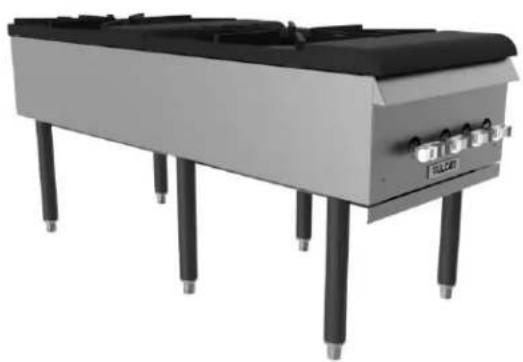
3D rendering of a portable electronic device with black and gray casing, supported by four vertical posts (no visible text or symbols)VSP200F
WSPR2F
For additional information on Vulcan or to locate an authorized parts and service provider in your area, visit our website at www.vulcanequipment.com
IMPORTANT FOR YOUR SAFETY
THIS MANUAL HAS BEEN PREPARED FOR PERSONNEL QUALIFIED TO INSTALL GAS EQUIPMENT, WHO SHOULD PERFORM THE INITIAL FIELD START-UP AND ADJUSTMENTS OF THE EQUIPMENT COVERED BY THIS MANUAL.
POST IN A PROMINENT LOCATION THE INSTRUCTIONS TO BE FOLLOWED IN THE EVENT THE SMELL OF GAS IS DETECTED. THIS INFORMATION CAN BE OBTAINED FROM THE LOCAL GAS SUPPLIER.
IMPORTANT
IN THE EVENT A GAS ODOR IS DETECTED, SHUT DOWN UNITS AT MAIN SHUTOFF VALVE AND CONTACT THE LOCAL GAS COMPANY OR GAS SUPPLIER FOR SERVICE.
FOR YOUR SAFETY
DO NOT STORE OR USE GASOLINE OR OTHER FLAMMABLE VAPORS OR LIQUIDS IN THE VICINITY OF THIS OR ANY OTHER APPLIANCE.
WARNING
Improper installation,
adjustment, alteration, service or maintenance can cause property damage, injury, or death. Read the installation, operating and maintenance instructions thoroughly before installing or servicing this equipment.
IN THE EVENT OF A POWER FAILURE, DO NOT ATTEMPT TO OPERATE THIS DEVICE.
INSTALLATION, OPERATION AND CARE OF STOCKPOT RANGE
GENERAL
Stockpot ranges are designed for commercial use only and feature fast, efficient gas heat. Each burner is controlled by an adjustable gas valve. Heavy-duty, cast iron top grate(s) are easily removed for cleaning when cool. A grease drawer is provided to collect fat run-off; it opens to the front for inspection or drain-off.
| Model | # of Burners | Natural Gas BTU/hr Input Rating | Propane Gas BTU/hr Input Rating |
| VSP100,WSPR1 | 2 | 110,000 | 90,000 |
| VSP200F,WSPR2F | 4 | 220,000 | 180,000 |
INSTALLATION
UNPACKING
This stockpot was inspected before leaving the factory. The carrier assumes full responsibility for the safe delivery upon acceptance of the shipment. Check for possible shipping damage immediately after receipt.
If the stockpot is found to be damaged, complete the following steps:
- Carrier must be notified within 5 business days of receipt.
- Carrier's local terminal must be notified immediately upon discovery (note time, date, and who was spoken to), and follow up and confirm with written or electronic communication.
- All original packing materials must be kept for inspection purposes.
- The stockpot cannot have been moved, installed, or modified.
- Notify Vulcan Customer Service immediately at 800-814-2028.
Remove all packing material and protective plastic from the surfaces of the unit. Before installing, verify that the type of gas (natural or propane) and the clearance dimensions agree with the specifications on the rating plate which is located at the back of the stockpot.
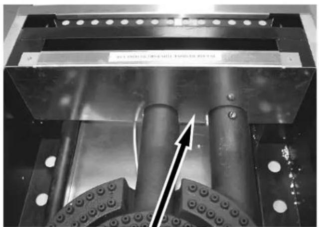
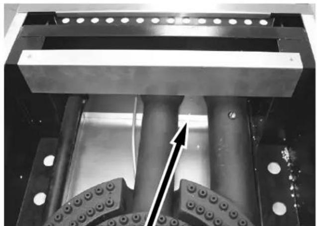
NOTICE The burner shipping bracket(s) labeled "Please remove this part before use" must be removed before the stockpot range is used.
natural_image
Mechanical assembly with cylindrical components and mounting holes, no visible text or symbolsSHIPPING BRACKET IN PLACE
natural_image
Mechanical assembly with cylindrical components and a directional arrow indicating motion (no text or symbols)SHIPPING BRACKET REMOVED
LOCATION
The installation location must be kept free and clear of combustibles. Do not obstruct the flow of combustion and ventilation air. DO NOT install the stockpot adjacent to open burners or fryers.
Sufficient air should be allowed to enter the room to compensate for the amount of air removed by any ventilating system and for combustion of the gas burners. Do not obstruct the air flow into and around the appliance. Do not obstruct the flow of flue gases through and above the stockpot top grate. Position the stockpot in its final location. Check that there are sufficient clearances to service the stockpot and to make the required gas supply connection(s). Provide 24" clearance at the front for cleaning, maintenance, service and proper operation.
| Minimum Clearance | Combustible Construction | Non-Combustible Construction |
| Rear | 24" | 4" |
| Sides | 18" | 0" |
INSTALLATION CODES AND STANDARDS
The Stockpot Range must be installed in accordance with:
In the United States of America:
-
State and local codes.
-
National Fuel Gas Code, ANSI-Z223.1/NFPA #54 (latest edition). This shall include but not be limited to: NFPA #54 Section 10.3.5.2 for Venting. Copies may be obtained from The American Gas Association Accredited Standards Committee Z223, @ 400 N. Capital St. NW, Washington, DC 20001 or the Secretary Standards Council, NFPA, 1 Batterymarch Park Quincy, MA 02169-7471
NOTE: In the Commonwealth of Massachusetts
All gas appliances vented through a ventilation hood or exhaust system equipped with a damper or with a power means of exhaust shall comply with 248 CMR.
- NFPA Standard # 96 Vapor Removal from Cooking Equipment, latest edition, available from the National Fire Protection Association, Batterymarch Park, Quincy, MA 02269.
In Canada:
-
Local codes.
-
CAN/CSA-B149.1 Natural Gas Installation (latest edition)
-
CAN/CSA-B149.2 Propane Installation Code (latest edition), available from the Canadian Gas Association, 178 Rexdale Blvd., Etobicoke, Ontario, Canada M9W 1R3
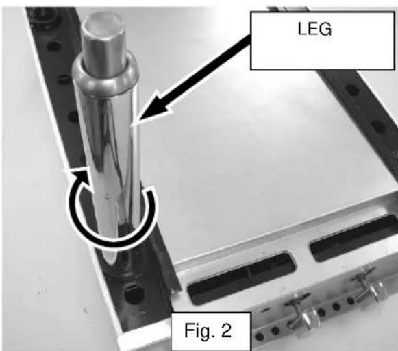
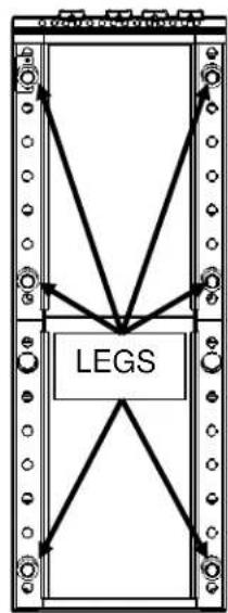
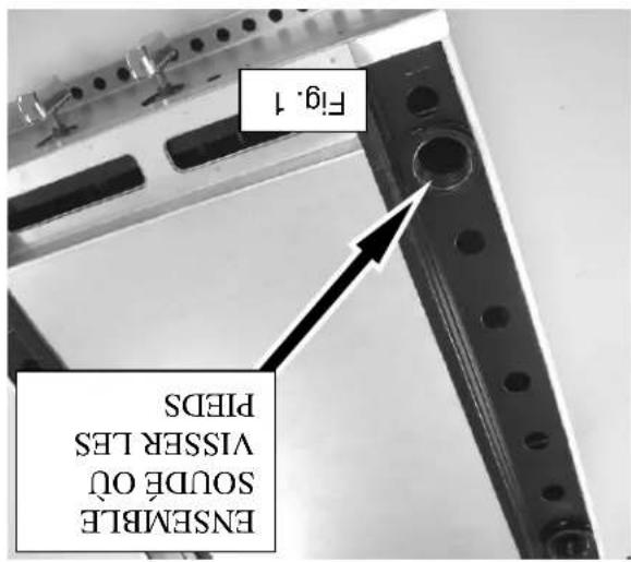
LEG INSTALLATION
WARNING The stockpot range is shipped without the legs attached. The stockpot range must not be operated without the legs attached to the unit.
-
Remove cast iron grate and burners from chassis.
-
Turn chassis upside down and locate threaded leg weldments (Fig. 1).
-
Screw legs into threaded leg weldments until tight (Fig. 2). Use a pipe or strap wrench with a towel (so as not to scratch leg) if needed to firmly tighten legs.

-
Continue process until all legs are installed. Single stockpots will have four legs and double stockpots will have six legs.
-
Return stockpot to upright position; reinstall burners and grates.
LEG ORIENTATION


flowchart
graph TD
    A["LEGS"] --> B["Node 1"]
    A --> C["Node 2"]
    A --> D["Node 3"]
    A --> E["Node 4"]
    A --> F["Node 5"]
    A --> G["Node 6"]
    A --> H["Node 7"]
    A --> I["Node 8"]
    A --> J["Node 9"]
    A --> K["Node 10"]
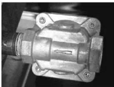
GAS PRESSURE REGULATOR INSTALLATION
Gas regulator pressure is preset at 5" Water Column (W.C.) f or natural gas, and 10" W.C. for propane gas. Minor adjustments may be required based on site specific gas pressure.
Install the regulator as close to the stockpot on the gas supply line as possible. Make sure that the arrow on the underside of the regulator is oriented in the direction of gas flow to the stockpot (Fig. 3) and the regulator is positioned with the vent plug and adjustment screw upright (Fig. 4).
natural_image
Close-up of a mechanical component with no visible text or symbolsFig. 3

natural_image
Close-up of a metallic mechanical valve component with bolts and housing (no visible text or symbols)Fig. 4
The minimum supply pressure (upstream of the regulator) should be 7-9" W.C. for natural gas and 11-12" W.C. for propane gas. At no time should the hotplate be connected to supply pressure greater than 12 psig (3.45 kPa) or 14" W.C.
LEVELING
The Stockpot Range is equipped with legs. Turn the feet at the bottom of the legs in or out to level the Stockpot Range in the final installed location.
VENTILATION HOOD
The stockpot should be installed under a suitable ventilation hood. For safe operation and proper ventilation, keep the space between the stockpot and vent hood free from any obstructions.
GAS CONNECTION
The data plate on the rear of the stockpot indicates the type of gas your unit is equipped to burn. DO NOT connect to any other gas type.
NOTICE Gas supply connections and any pipe joint compound must be resistant to the action of propane gases.
Purge the supply line to clean out any dust, dirt, or any foreign matter before connecting the line to the unit.
Codes require that a gas shut-off valve be installed in the gas line ahead of the stockpot. The gas supply line must be at least the equivalent of 34 " iron pipe.
A pressure regulator is supplied and must be installed outside of the broiler when making the gas supply connection. Standard orifices are set for 5"WC (Water Column) for Natural Gas — 10"WC (Water Column) for Propane. Use the ^1/8 pipe tap on the burner manifold for checking pressure. Make sure the gas piping is clean and free of obstructions, dirt, and piping compound.
An adequate gas supply is necessary. Undersized or low pressure lines will restrict the volume of gas required for satisfactory performance. A minimum supply pressure of 7" W.C. for natural gas and 11" W.C. for propane gas is recommended. With all units operating simultaneously, the manifold pressure on all units should not show any appreciable drop.
When testing the gas supply piping system, if test pressures exceed 12 psig (3.45 kPa), the stockpot and its individual shutoff valve must be disconnected from the gas supply piping system. When test pressures are 12 psig (3.45 kPa) or less, the stockpot must be isolated from the gas supply piping system by closing its individual manual shut-off valve during any pressure testing of the system.
WARNING Prior to lighting, check all joints in the gas supply line for leaks. Use soap and water solution. Do not use an open flame.
OPERATION
WARNING The stockpot range and its parts are hot. Use care when operating, cleaning or servicing the stockpot range.
CONTROLS
The burner is in two sections, controlled by two heavy duty infinite control valves. The center “Star” section (Fig. 6) is on separate burner with an input of 55,000 BTU/hr. It is controlled by the right burner valve knob. The outer circle of the burner (Fig. 6) is the other separate 55,000 BTU/hr input burner, controlled by the left burner valve knob.
These two separate burners provide heat flexibility. With one burner off and the second burner set low, up to both burners full on, you can move from low simmer on up to 110,000 BTU/hr input.
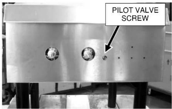
Fig. 5
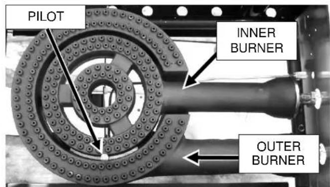
Fig. 6
LIGHTING INSTRUCTIONS
- Turn all burner valves to OFF position and wait 5 minutes.
- Turn gas shutoff valve ON.
- Light standing pilot with a lit taper (see Fig 6). Adjust pilot to 14 " high flame, if necessary, by turning pilot valve adjusting screw (see Fig. 5) counterclockwise to increase or clockwise to decrease flame.
- Turn burner valve to ON position.
- If pilot does not light, turn main gas supply OFF and repeat steps 1 through 4.
TO COMPLETELY SHUTDOWN THE BURNERS AND PILOT LIGHTS
For complete shutdown: Turn the main gas supply valve OFF.
CLEANING
Top grate(s) may be immersed in strong commercial cleaning compound overnight. In the morning, rinse with hot water to remove any residues of cleaning compound. Thoroughly dry and apply a light coating of cooking oil to prevent rusting.
Stainless steel surfaces may be cleaned using damp cloth with mild detergent and water solution. Places where fat, grease, or food can accumulate must be cleaned regularly.
The grease drawer should be emptied regularly when cool.
MAINTENANCE
WARNING
The stockpot range and its parts are hot. Use care when operating, cleaning or servicing the stockpot range.
LUBRICATION
All valves must be checked and lubricated periodically. At the first sign of sticking, valves should be lubricated by a trained technician using high temperature grease. Check with your service agency for details.
SERVICE AND PARTS INFORMATION
Contact the Service Contractor in your area to obtain service and parts information. For a complete listing of Service and Parts depots refer to www.vulcanquipment.com.
When calling for service the following information should be available from the appliance serial plate: Model Number, Serial Number and Gas Type. The appliance serial plate is located on the back panel.
TROUBLESHOOTING
| PROBLEM | POSSIBLE CAUSES |
| Pilot Outage | 1. Pilot flame too low2. Restriction in pilot orifice3. Restriction in pilot valve |
| Improper burner combustion | 1. Improper ventilation |
| Poor Ignition | 1. Insufficient gas input2. Poor air-gas adjustment3. Restriction in pilot orifice4. Restriction in main burner ignition port5. Restriction in control valve6. Restriction in gas orifice |
NOTES
natural_image
Close-up of a metallic mechanical component with bolts and mounting holes (no visible text or symbols)Fig. 3

natural_image
Close-up of a mechanical component with metallic parts and bolted joints (no visible text or symbols)verticale (Fig. 4).
A AVE R T I S S E M E N T
INSTALLATION DES PIEDS
1R3.
Association, Batterymarch Park, Quincy, MA 02269.
natural_image
3D rendering of a mechanical device with multiple vertical posts and a base (no visible text or symbols)WSPRI
VSP100

natural_image
3D rendering of a wireless router with three vertical pins and a base-mounted fan (no visible text or symbols)MODELS
MODE D'INSTALACTION ET MODE D'EMPLOI CUISINE RE A MARMITES
WOLF
VILDA

- IMPORTANT FOR YOUR SAFETY
- IMPORTANT
- FOR YOUR SAFETY
- WARNING
- INSTALLATION, OPERATION AND CARE OF STOCKPOT RANGE
- GENERAL
- INSTALLATION
- UNPACKING
- LOCATION
- INSTALLATION CODES AND STANDARDS
- The Stockpot Range must be installed in accordance with:
- NOTE: In the Commonwealth of Massachusetts
- LEG INSTALLATION
- WARNING The stockpot range is shipped without the legs attached. The stockpot range must not be operated without the legs attached to the unit.
- GAS PRESSURE REGULATOR INSTALLATION
- LEVELING
- VENTILATION HOOD
- GAS CONNECTION
- OPERATION
- CONTROLS
- LIGHTING INSTRUCTIONS
- TO COMPLETELY SHUTDOWN THE BURNERS AND PILOT LIGHTS
- CLEANING
- MAINTENANCE
- LUBRICATION
- SERVICE AND PARTS INFORMATION
- NOTES
- INSTALLATION DES PIEDS
Brand : WOLF
Model : WSPR2F
Category : Hot plate