HRS400X2004 - Vacuum Cleaner Envira-North - Free user manual and instructions
Find the device manual for free HRS400X2004 Envira-North in PDF.

User questions about HRS400X2004 Envira-North
0 question about this device. Answer the ones you know or ask your own.
Ask a new question about this device
Download the instructions for your Vacuum Cleaner in PDF format for free! Find your manual HRS400X2004 - Envira-North and take your electronic device back in hand. On this page are published all the documents necessary for the use of your device. HRS400X2004 by Envira-North.
USER MANUAL HRS400X2004 Envira-North
text_image
Altra-Air SailfinMetric & Imperial
DESIGN & ENGINEERING GUIDE
ENVIRA-NORTH
SYSTEMS LIMITED
(519) 527-2198
www.enviranorth.com
ALTRA-AIR SAILFIN FANS
Thank you for incorporating Envira-North System's Altra-Air Sailfin Fans into your project. Envira-North Systems Ltd. recognizes that energy savings is a top priority in today's economic and social environment. Bringing over 50 years of ventilation expertise, we've established ourselves by providing quality products accompanied by the best after-sales service in the industry, while contributing to the effectiveness of heating / cooling and ventilation systems.
Our mission is to continually develop and provide quality, cost efficient ventilation solutions that improve energy consumption and increase comfort levels for the occupants of large structures.
Energy consumption has grown to be a critical factor in business worldwide. Envira-North will continue to develop and provide solutions to improve energy consumption while increasing occupant productivity inside structures around the globe. Ample research is available to show that adequate fresh air exchange is crucial for workers, students, animals and home occupants to perform at their best. A well designed ventilation scheme can:
- Lower temperatures in buildings by cooling roof spaces and removing trapped ceiling heat through ceiling grilles.
- Improve air quality by lowering impurity levels caused by human respiration and toxic chemical emissions.
Altra-Air Sailfin Fans are a green power breakthrough which allows our High Volume Low Speed (HVLS) fans to deliver previously impossible levels of performance. These HVLS fans are simply outstanding when compared to what was previously considered the state-of-the-art fan.
- 5 blades are 25% more aerodynamically efficient (they move more air more smoothly).
• Aerodynamic blade noise (the main source of fan noise) is less than 1/5 of conventional fans.
• Best of all, they consume 20% less power.
We are proud to acknowledge that no other blade can match a Sailfin blade when it comes to generating substantially greater lift while reducing drag.
This Engineering and Design Guide should give you everything you need to successfully include Altra-Air Sailfin fans into your project.
Thank you for giving Envira-North Systems Ltd. the opportunity to be incorporated into your project's design plans. If you have any questions, concerns or comments please do not hesitate to contact the Envira-North office at 1(519)527-2198 or visit our website at www.enviranorth.com.
TABLE OF CONTENTS
INTRODUCTION....2 - 7
Why Choose Envira-North....4
The Sailfin Blade Advantage 4
Benefits of Sailfin....4
Warranty Overview 5
Sailfin Introduction....6
Safety System 7
COMPONENTS 8 - 15
Fan Components Diagram 8
Mounting Applications....9
Fan Blade Clearance.... 10
1FT Mount.... 11
2FT Mount.... 12
4FT Mount....13
1FT Extension 14
1FT Extension 15
FAN SPECIFICATIONS.... 16 - 24
3.7 M (12 FT) Sailfin 16 - 17
4.9 M (16 FT) Sailfin 18 - 19
6.1 M (20 FT) Sailfin 20 - 21
7.3 M (24 FT) Sailfin 22 - 23
Specifications Chart.... 24
Guy Wires 25
Packaging / Shipping 26
Certification Details 27
Control Options....28-29
Limitation of Warranty & Liability 30-32
Maintenance Schedule.... 33-34
Engineers requiring AutoCAD or SolidWorks drawings can download them by accessing the Envira-North 'Dealer Login' page on our website at www.enviranorth.com/dealerlogin. Please note that an authorised username and password is required to access this secure area of our site. Please contact Envira-North at 1(519)527-2198 to receive a username and password.
WHY CHOOSE ENVIRA-NORTH SYSTEMS LTD?
We are Canada's largest supplier of industrial/commercial big ceiling (HVLS - High Volume Low Speed) fans and claim 75% of the Canadian market for industrial/commercial destratification and ventilation fans. Applications include hangars, warehouses, hockey rinks, shopping malls, distribution centres, office buildings, dairy farms, or any other facility with high ceilings. Envira-North Systems has been featured on CBC, MSNBC, A Channel, and in Discover Magazine, Toronto Star, Christian Science Monitor and Material Handling Management.
Envira-North Systems Ltd. staff bring to you over 50 years of ventilation expertise. We pride ourselves in providing the best after sales service in the industry. We recognize that energy savings is a top priority in today's environment.
Envira-North Systems Ltd. has recognized a worldwide need to reduce energy consumption by contributing to the effectiveness of heating, cooling and ventilation systems. Our products and systems enable your building to perform better; save on heating, cooling, mechanical operating costs and provide a healthier environment for the occupants of the structure.
Salfin blades outperform all conventional airfoils. They accomplish this by:
- Offering an angle of attack up to 23^ .
- Eliminating span-wise pumping; the primary cause of efficiency loss in all rotating systems.
- Eliminating tip stalling; the primary cause of blade noise and damaging vibration.
- Variableariable pitch modulated trailing-edge airfoil removes the inefficiencies created by differentiating rotational HVLS Fan speeds.
THE BENEFITS OF SAILFIN
- Quiet speed and efficient operation, no annoying high speed circulating and exhaust fans.
• Virtually maintenance free (recommended inspection every 20,000 hours).
- Inexpensive to operate. Costs approximately 6 cents per hour for one fan at 1 HP.
- Greatly reduces "recovery" time when overhead doors are open with a constant air flow throughout.
- Provides a constant, even temperature from floor to ceiling and wall to wall.
- Will minimize the need for expensive duct work in new construction for both heating and air conditioning systems.
• A comfortable workplace environment increases productivity and decreases absenteeism.
INSTALLATION
Altra-Air Sailfin Fans come as a complete system including power unit, mounting hardware, wiring kit (optional) and low voltage controller (optional). Having everything included in this complete package streamlines installation and eliminates the costly search for components and hardware.
WARRANTY
Altra-Air Sailfin fans are of industrial grade construction and should provide many years of virtually maintenance free use. Standard 3 Year Limited Warranty duration is as follows:
Air Foil Shaped Blade Lifetime Warranty
Aluminum Alloy Hub Lifetime Warranty
Motor 3 Year Limited Warranty
Gear Reducer 3 Year Limited Warranty
VFD Control Panel 3 Year Limited Warranty
Labour 1 Year Limited Warranty (pre-approved)
Custom fan wraps/paint 1 Year Limited Warranty
Please see page 28 of this document for complete warranty information including specifics and warranty exclusions. Use the above warranty information as a general guideline only.
ALTRA-AIR SAILFIN FANS
Altra-Air HVLS fans blanket a very large area with constantly moving air to create an expansive comfort zone. As a result, the big ceiling fan can create an evaporative cooling effect of three to four degrees Celsius throughout the facility.
During the heating season, the Altra-Air HVLS fan technology can de-stratify uneven temperatures that can be in excess of fifteen degrees Celsius from ceiling to floor. This results in significant energy savings since the heating system cycles less frequently.
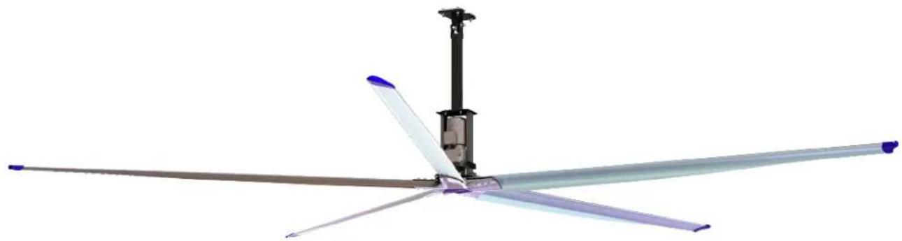
natural_image
3D rendering of a five-blade propeller with extended blades and a central fan assembly (no text or symbols visible)SAFETY SYSTEMS
In regards to safety issues concerning Altra-Air fans we would like to point out the measure we took to ensure the safety of our fans.
- Safety Cable - This cable ties together the vertical drop and the motor/gear reducer frame to the physical structure of your building.
- Safety Clips - These clips prevent the hub from falling in case of failure of the Fenner drive (nut) that holds the hub to the shaft of the gear reducer.
- Guy Wires - The wires have two functions; first, to avoid unnecessary sway of the fan in case of unbalanced blade(s) and second, to avoid large movements due to wind or draft.
- Mount - The mounting hardware has been designed and engineered to support the weight of the fan and provide a secure connection to the structure.
FAN COMPONENTS DIAGRAM

text_image
(2) Bolt 3/4" x 4 ½" UNC (2) Nylock 3/4" UNC Structural Support of the building (1) Mounting Plate + (2) Shim Plates + (2) Holding Plates (4) Bolt ½" x 2½" UNC FT (8) Washer Flat ½" (4) Nylock ½" UNC Safety Cable (1) Cable 3/16" SS (Length 6.5 ft) (4) Cable Clamps 3/16" Standard Mount (Available in approx 12", 24" or 48" lengths, custom lengths are optional) (4) Bolts ½" x 1½" UNC (8) Washers Flat ½" (4) Nylock ½" UNC Safety Cable (1) Cable 3/16" SS (Length 3 ft) (4) Cable Clamps 3/16" Extension Fan Frame Typical Guy Wire: (4) Cable 1/8" SS (60 ft length provided to equal 4 @ 15 ft) (8) Thimbles 1/4" SS (16) Cable Clamps 1/8" Guy Wires (1) Hub (5) Blades (not shown) (10) Bolts 3/8" x 3½" UNC (5) Bolts 3/8" x 4" UNC (15) Nylocks 3/8" UNC (30) Washers Flat 3/8" (1) Trantorque Nut (specific torque setting required) (1) Label "Envira-North (5) Blade toppersNote: All bolts are "Grade 5 UNO" FT = Fully Threaded (#) = Quantity Supplied
DIFFERENT MOUNTING APPLICATIONS

text_image
OWSJ MOUNT PURLIN Z MOUNT I BEAM MOUNT WOOD BEAM MOUNT CONCRETE BEAM MOUNTFor a complete review of the mounting system and how it applies to your application, please reference the Altra-Air Sailfin Installation Guide.
To obtain a copy, please contact us by phone at 1-519-527-2198 or by email at bigair@enviranorth.com.
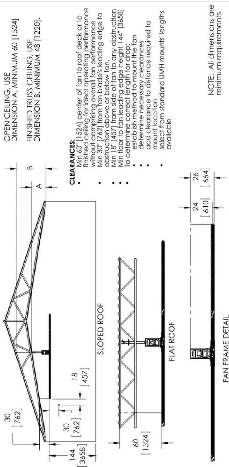
Min 60" [1524] center of fan to roof deck or to finished ceiling for ideal operating performance without comprising overall fan performance Min 30" [762] from fan blade's leading edge to obstruction above or below fan. Min 18" [457] from side of fan to any obstruction Min floor to fan leading edge height 144" [3658] To determine correct length for drop: establish method to mount the fan determine necessary clearances add clearance to distance required to mount location select from standard UMH mounts' lengths available
NOTE: All dimensions are minimum requirements
Dimensions are in inches, metric dimensions [mm].
Q:\01_Envira-North\SolidWorks (DWG) EN\Applications\
| MATERIAL | COMMENTS:MINIMUM DIMENSIONSFOR CLEARANCENote: Contractor is responsible forverifying all site conditions to include fielddimensions where applicable. It the contractor elects tomake any changes without notifying Envira-North SystemsLtd. the contractor is responsible for the same. Alldrawings are in to be used as general architectural intent onlyunless otherwise stamped. See Engineering drawings forstructural design information. Contractor to ensure that allbuilding departments andauthorities are informed in regard to the work and that alpermils are retained before commencing for work. | DRAWN MITCHELL BEERMAN Drawing Date:9/27/2011 | Envira-North Systems Ltd. | |||
| Q.A. | ||||||
| FINISH | Last Revised Date: | Checked By: CDV | TITLE:MINIMUM CLEARANCES | |||
| VENDORS NUMBER: | ENG APPR. | Checked Date: 09/27/2011 | ||||
| DO NOT SCALE DRAWINGPROPRIETARY AND CONFIDENTIALTHE INFORMATION CONTAINED IN THIS DRAWING IS THE SOLEPROPERTY OF ENVIRA-NORTH SYSTEMS LTD. ANYREPRODUCTION IN PART OR AS A WHOLE WITHOUT THEWRITTEN PERMISSION OF ENVIRA-NORTH SYSTEMS LTD ISPROHIBITED. SHOULD THERE BE ANY DISCREPANCIES WITHTHIS CONSTRUCTION DRAWING. ENVIRA-NORTH SYSTEMS LTDSHOULD BE CONTACTED IMMEDIATELY FOR RESPONSE | ENG APPR. Date: | MFG APPR. | ||||
| UNLESS OTHERWISE SPECIFIED:DIMENSIONS ARE IN INCHESTOLERANCES.FRACTIONA# 1/16ANGULAR: MACH ± 0.1* BEND ± 0.5*TWO PLACE DECIMAL ± 0.060THREE PLACE DECIMAL ± 0.030 | Last Saved Date:Tuesday, September 27, 2011 3:19:11 PM | |||||
| REVISIONS:ADJUSTED MIN REQUIREMENTS | ||||||
| SIZEA | DWG. NO.CONSTRAINTS | REV | ||||
| SCALE: N.T.S. WEIGHT: | ||||||
5 4 3 2 1
1 FT MOUNT
| ITEM NO. | PART NUMBER | DESCRIPTION | QTY. |
| 1 | EN823X8425 | DROP H TYPE 1 FT | 1 |
| 2 | EN823x8418 | UMH COUPLER PC | 1 |
| 3 | EN823x8417 | UMH UPPER PIVOT PLATE | 1 |
| 4 | EN823X8401 | MANUFACTURED I-BEAM SPACER | 2 |
| 5 | EN823x8402 | MANUFACTURED I-BEAM CLAMP | 2 |
2 FT MOUNT
| ITEM NO. | PART NUMBER | DESCRIPTION | QTY. |
| 1 | EN823X8426 | DROP H TYPE 2 FT | 1 |
| 2 | EN823x8418 | UMH COUPLER PC | 1 |
| 3 | EN823x8417 | UMH UPPER PIVOT PLATE | 1 |
| 4 | EN823X8401 | MANUFACTURED I-BEAM SPACER | 2 |
| 5 | EN823x8402 | MANUFACTURED I-BEAM CLAMP | 2 |
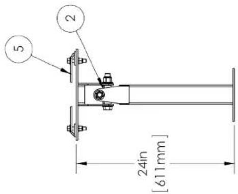
text_image
24in [611mm] 5 2
natural_image
Technical line drawing of a mechanical support structure (no text or symbols)
text_image
Technical diagram showing two mechanical assembly setups with numbered components and alignment indicatorsDIMENSIONS SUBJECT TO CHANGE WITHOUT NOTICE.
| MATERIAL AS SPECIFIED | COMMENTS:PART #S MAY VARY DEPENDING ON METRIC OR IMPERIAL HARDWARE REQUIREMENTS | DRAWN CFO | Drawing Date: 6/16/2011 | Envira-North Systems Ltd. | |||
| Q.A. | |||||||
| FINISH AS SPECIFIED | Last Revised Date: | Checked By: CDV | TITLE:2 FT UMH MOUNT | ||||
| VENDORS NUMBER: | ENG APPR. | Checked Date: 6/16/2011 | |||||
| DO NOT SCALE DRAWING | ENG APPR. Date: | MFG APPR. | |||||
| PROPRIETARY AND CONFIDENTIALTHE INFORMATION CONTAINED IN THIS DRAWING IS THE SOLE PROPERTY OF ENVIRA NORTH SYSTEMS LTD. ANY REPRODUCTION IN PART OR AS A WHOLE WITHOUT THE WRITTEN PERMISSION OF ENVIRA NORTH SYSTEMS LTD IS PROHIBITED SHOULD THERE BE ANY DISCREPANCIES WITH THIS CONSTRUCTION DRAWING ENVIRA NORTH SYSTEMS LTD SHOULD BE CONTACTED IMMEDIATELY FOR RESPONSE | REVISIONS: | UNLESS OTHERWISE SPECIFIED:DIMENSIONS ARE IN INCHES TOLERANCES:FRACTIONAL ±ANGULAR: MACH ± BEND ±TWO PLACE DECIMAL ±THREE PLACE DECIMAL ± | Lost Saved Date:Wednesday, October 19, 2011 12:33:24 PM | SIZE DWG. NO.EN400X2002 | REV | ||
| SCALE: 1:2 WEIGHT: 29.65 | |||||||
5 4 3 2 1
4 FT MOUNT
| ITEM NO. | PART NUMBER | DESCRIPTION | QTY. |
| 1 | EN823X8428 | DROP H TYPE 4 FT | 1 |
| 2 | EN823x8418 | UMH COUPLER PC | 1 |
| 3 | EN823x8417 | UMH UPPER PIVOT PLATE | 1 |
| 4 | EN823x8402 | MANUFACTURED I-BEAM CLAMP | 2 |
| 5 | EN823X8401 | MANUFACTURED I-BEAM SPACER | 2 |
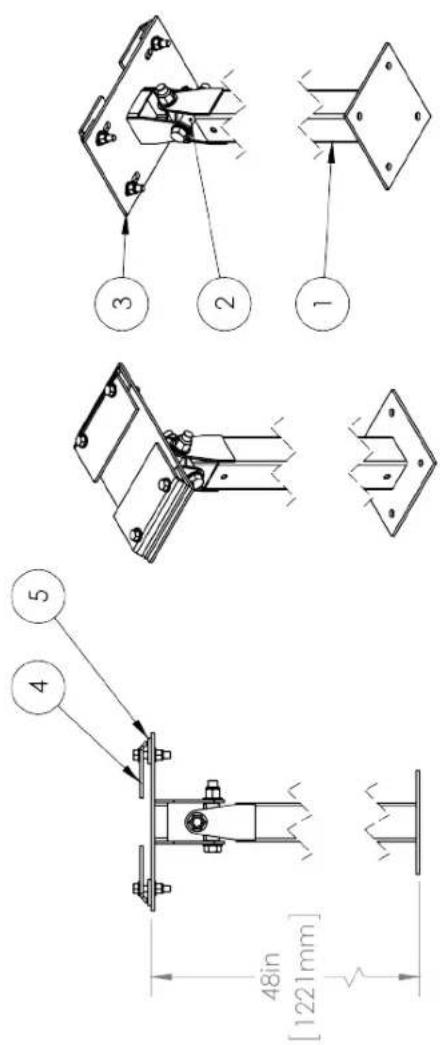
text_image
48in [1221mm] ① ② ③ ④ ⑤
DIMENSIONS SUBJECT TO CHANGE WITHOUT NOTICE.
| MATERIAL AS SPECIFIED | COMMENTS:PART #S MAY VARYDEPENDING ON METRIC ORIMPERIAL HARDWAREREQUIREMENTS | DRAWN CFO | Drawing Date: 6/16/2011 | Envira-North Systems Ltd. | ||
| Q.A. | ||||||
| FINISH AS SPECIFIED | REVISIONS: | Last Revised Date: | Checked By: CDV | TITLE:4 FT UMH MOUNT | ||
| VENDORS NUMBER: | ENG APPR. | Checked Date: 6/16/2011 | ||||
| DO NOT SCALE DRAWING | ENG APPR. Date: | MFG APPR. | ||||
| PROPRIETARY AND CONFIDENTIALTHE INFORMATION CONTAINED IN THIS DRAWING IS THE SOLEPROPERTY OF ENVIRA NORTH SYSTEMS LTD. ANYREPRODUCTION IN PART OR AS A WHOLE WITHOUT THEWRITTEN PERMISSION OF ENVIRA NORTH SYSTEMS LTD ISPROHIBITED. SHOULD THERE BE ANY DISCREPANCIES WITHTHIS CONSTRUCTION DRAWING. ENVIRA NORTH SYSTEMS LTD SHOULD BE CONTACTED IMMEDIATELY FOR RESPONSE | UNLESS OTHERWISE SPECIFIED:DINENSIONS ARE IN INCHES TOLERANCES:FRACTIONAL ±ANGULAR: MACH ± BEND ±TWO PLACE DECIMAL ±THREE PLACE DECIMAL ± | Lost Saved Date:Wednesday, October 19, 2011 12:33:20 PM | SIZE DWG. NO.EN400X2004 | REV | ||
| SCALE: 1:2 WEIGHT: 39.22 | ||||||
5 4 3 2 1
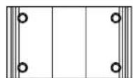
2 FT EXTENSION
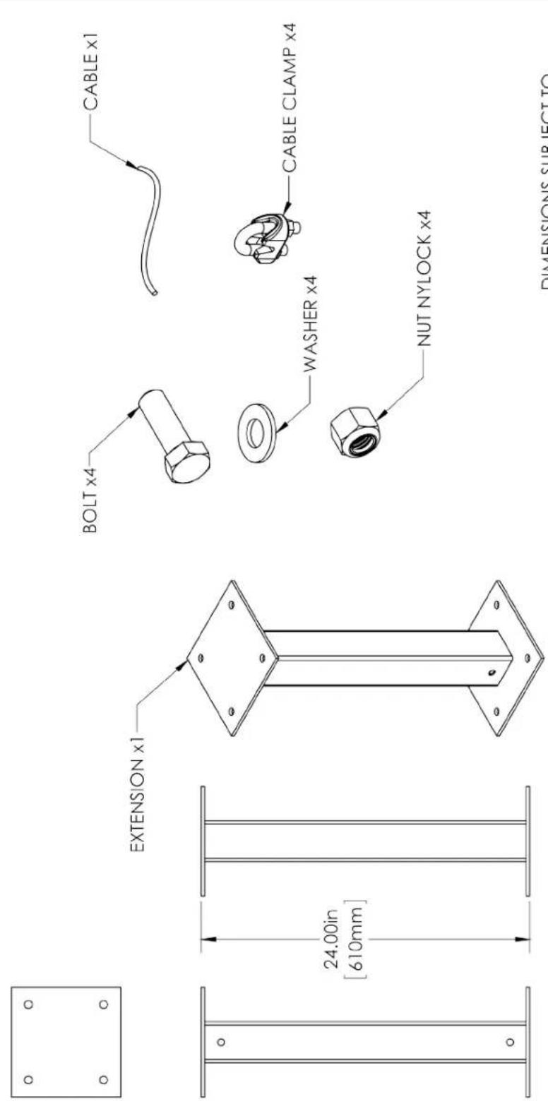
DIMENSIONS SUBJECT TO CHANGE WITHOUT NOTICE.
Q:\01_Environ-North\SoldWorks (DWG) EN\EN405X1002
| MATERIAL AS SPECIFIED | COMMENTS:PART #'S MAY VARY DEPENDING ON METRIC OR IMPERIAL HARDWARE REQUIREMENTS | DRAWN CEO | Drawing Date: 6/17/2011 | Envira-North Systems Ltd. | ||
| Q.A. | ||||||
| FINISH AS SPECIFIED | Last Revised Date: | Checked By: CDV | TITLE:2FT PKG EXTENSION MOUNT | |||
| VENDORS NUMBER: | ENG APPR. | Checked Date: 6/17/2011 | ||||
| DO NOT SCALE DRAWING | ENG APPR. Date: | MFG APPR. | ||||
| PROPRIETARY AND CONFIDENTIALTHE INFORMATION CONTAINED IN THIS DRAWING IS THE SOLEPROPERTY OF ENVIRA NORTH SYSTEMS LTD. ANYREPRODUCTION IN PART OR AS A WHOLE WITHOUT THEWRITTEN PERMISSION OF ENVIRA NORTH SYSTEMS LTD ISPROHIBITED. SHOULD THERE BE ANY DISCREPANCIES WITHTHIS CONSTRUCTION DRAWING. ENVIRA NORTH SYSTEMS LTD SHOULD BE CONTACTED IMMEDIATELY FOR RESPONSE. | Note: Contractor is responsible forifying all site conditions to include fielddimensions where applicable. If the contractor selects toname any changes without modifying Eniva-North SystemLtd. the contractor is responsible for the same. Alldrights are it to be used as general architecture with onlyinture otherwise started. The Engineering drawings fornatural design definition. Contractor has not installedluding partners andas indicated as information right to the April and shallpresent an indirect table confirming this use | UNLESS OTHERWISE SPECIFIED:DIMENSIONS ARE IN INCHESIOLERANCES.FRACTIONALE 1/16ANGULAR: MACHA 0.1*BEND ± 0.5*TWO PLACE DECIMAL ± 0.060THREE PLACE DECIMAL ± 0.030 | Lost Saved Date:Wednesday, October 19, 2011 10:35:20 AMREVISIONS: | SIZE DWG. NO.EN405X1002 | REV | |
| SCALE: 1:8 | WEIGHT: | |||||
5 4 3 2 1
4 FT EXTENSION
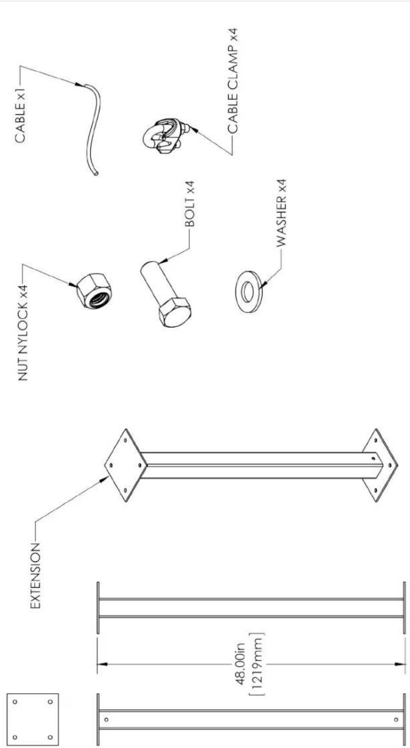
DIMENSIONS SUBJECT TO CHANGE WITHOUT NOTICE.
| MATERIAL AS SPECIFIED | COMMENTS:PART #S MAY VARY | DRAWN CEO | Drawing Date: 6/17/2011 | Envira-North Systems Ltd. | |
| Q.A. | |||||
| FINISH AS SPECIFIED | DEPENDING ON METRIC OR IMPERIAL HARDWARE REQUIREMENTS | Last Revised Date: | Checked By: CDV | TITLE:4FT PKG EXTENSION MOUNT | |
| VENDORS NUMBER: | ENG APPR. | Checked Date: 6/17/2011 | |||
| DO NOT SCALE DRAWING | ENG APPR. Date: | MFG APPR. | |||
| PROPRIETARY AND CONFIDENTIALTHE INFORMATION CONTAINED IN THIS DRAWING IS THE SOLE PROPERTY OF ENVIRA NORTH SYSTEMS LTD. ANY REPRODUCTION IN PART OR AS A WHOLE WITHOUT THE WRITTEN PERMISSION OF ENVIRA NORTH SYSTEMS LTD IS PROHIBITED. SHOULD THERE BE ANY DISCREPANCIES WITH THIS CONSTRUCTION DRAWING. ENVIRA NORTH SYSTEMS LTD SHOULD BE CONTACTED IMMEDIATELY FOR RESPONSE. | Note: Contractor is responsible for:HTIFYing at site conditions to include field dimensions where applicable. If the contractor selects to manage any changes without modifying Eneris/North Systems Ltd. the contractor is responsible for the same. All strengths are it be used as general architecture, except only unless otherwise turned. For Existing drawing for inscale legal information, Contractor has not actual testing details and influences on information to be applied and shall permit or not related to considering this. | UNLESS OTHERWISE SPECIFIED:DIMENSIONS ARE IN INCHES IOLERANCES.FRACTIONALE 1/16ANGULAR: MACHA 0.1*BEND ± 0.5*TWO PLACE DECIMAL ± 0.060THREE PLACE DECIMAL ± 0.030 | Last Saved Date:Wednesday October 19, 2011 12:13:28 PMREVISIONS: | SIZE DWG. NO.EN405X1004 | REV |
| SCALE: 1:12 WEIGHT: | |||||
4 3 2 1
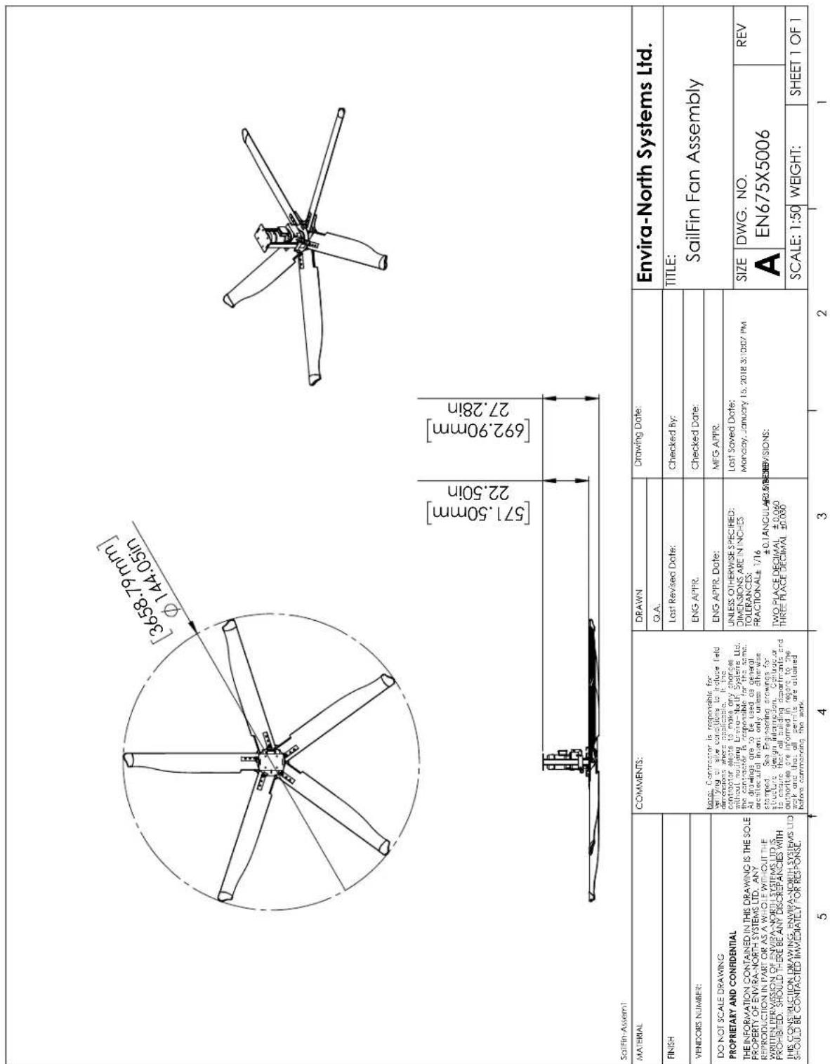
3.7 M (12 FT) ALTRA-AIR SAILFIN FAN SPEC DRAWING
text_image
[3658.79mm] φ144.05in [571.50mm] 22.50in [692.90mm] 27.28in Salifin-Assem1 MATERIAL COMMENTS: L###: Contractor is responsible for ###ing or side corrections to produce field dimensions where application. If the contactor pleets to make any changes without installing Drive-North Systems Ltd. the contractor is responsible for this same. All drawings are to be used as general architectural in## only unless otherwise stamped. See Engineering drawings for structure design instruction. Contractor to ensure that all building departments and authorities are informed in regard to the work and that all permits are attained before commanding the work. DRAWN DRAWN Drawing Date: Envira-North Systems Ltd. Q.A. LISTLE: SailFin Fan Assembly TITLE: TITLE: PROPRIETARY AND CONFIDENTIAL THE INFORMATION CONTAINED IN THIS DRAWING IS THE SOLE PROPERTY OF ENVIRA-NORTH SYSTEMS LTD., ANY REPRODUCTION IN PART OR AS A WHOLE WITHOUT THE WRITTEN PERMISSION OF ENVIRA-NORTH SYSTEMS LTD IS PROHIBITED. SHOULD THERE BE ANY DISCREPANCIES WITH THIS CONSTRUCTION DRAWING ENVIRA-NORTH SYSTEMS LTD. SHOULD BE CONTACTED IMMEDIATELY FOR RESPONSE: UNLESS OTHERWISE SPECIFIED; DIMENSIONS ARE IN INCHES TOLERANCES; FRACTIONAL± 1/16 ±0.1ANCULAR±0.5/16 TWO PLACE DECIMAL ±0.060 THREE PLACE DECIMAL ±0.050 UNLESS OTHERWISE SPECIFIED; DIMENSIONS ARE IN INCHES TOLERANCES; FRACTIONAL± 1/16 ±0.1ANCULAR±0.5/16 TWO PLACE DECIMAL ±0.060 THREE PLACE DECIMAL ±0.050 LISTE: DWG. NO. EN675X5006 REV SCALE: 1:50 WEIGHT: SHEET 1 OF 13.7 M (12 FT) ALTRA-AIR SAILFIN FAN SPECIFICATIONS
General
Model Number......EN675X5006
Diameter 3.7 m (12 ft)
Number of Blades
Motor Power 0.75 kW (1 HP)
Noise Level 62.5 dBA
Weight (no mount)....111 kgs (245 lbs)
Packaged Fan (30" x 31" x 32")....128.8 kgs (284 lbs*)
Packaged Blades (11" x 11" x 72")....50.4 kgs (111 lbs)
* Mounts, extensions & controls packages separately. Weights may vary.

CE
Performance
Maximum Velocity....1.96 m/s (386 ft/min)
Airflow 33,236 l/s (70,424 CFM)
Maximum Speed 105 RPM
Power Usage....782 W
Maximum Effective Diameter 24 m (80 ft)
Construction
Frame Galvanized Steel Frame
Hub 713 Cast Aluminum Alloy
Blades 6063 Extruded Anodized Aluminum
Blade End Caps....High Impact Polystyrene
Safety Components
Safety Cables....3/16" Stainless Steel
Guy Wires....1/8" Stainless Steel
Safety Clips ....Zinc Plated Steel
Mounting Hardware
Standard Mount......Universal I-Beam Clamp w/ Swivel
Standard Drop 1 ft / 2 ft / 4 ft
Drop Extensions (Optional) 1 ft / 2 ft / 4 ft
Mounting
Open Web Steel Joist (Optional)......Steel Beam With Brackets
Wood Beam Mount (Optional)......Steel Machined Mount Plates
Concrete Beam Mount (Optional)......Steel Beam with Matching Mount Plates
Purlin "Z" Mount (Optional)......Steel Beam Brackets
Steel Thickness Varies Depending on Beam Span....Consult Factory for Specifics
*Please see Altra-Air Installation Guide for more information regarding mounting hardware.
Gear Motor
Type......Helical Inline Reducer
HP....1 HP (50 Hz / 60 Hz)
Ratio 13.39
Volts....230 V / 400 V / 460 V / 575 V
Amps Consumed....3 A @ 230 V
Insulation Class
Torque 53 Nm (39 ft-lbs)
Thrust....125 N (28 lbs)
Fan Control
Enclosure IP65
Operation....Key Pad
Control Options (Not Included)....Low Voltage / Temperature Control
Standard Power 208 V / 230 V / 400 V / 460 V / 575 V
Special Wiring (Thermostats, Fire Alarm Interface, Networking Etc.)(Optional)......Consult Factory
50 / 60 Hz Operation
Warranty
Motor, Gearbox & Control Panel....3 Years
Blades, Hub & Mounting System......Lifetime
*Please see Altra-Air Installation Guide for warranty specifications and exclusions.
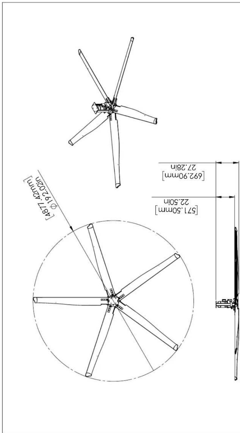
4.9 M (16 FT) ALTRA-AIR SAILFIN FAN SPEC DRAWING
text_image
[4877.42mm] φ19.202in [571.50mm] 22.50in [692.90mm] 27.28in| MATERIAL | COMMENTS: | DRAWN | Drawing Date: | Envira-North Systems Ltd. | ||
| Q.A. | ||||||
| FINISH | Lost Revised Date: | Checked By: | TITLE:SailFin Fan Assembly | |||
| VENDORS NUMBER: | ENG APPR. | Checked Date: | ||||
| DO NOT SCALE DRAWING PROPRIETARY AND CONFIDENTIALTHE INFORMATION CONTAINED IN THIS DRAWING IS THE SOLE PROPERTY OF ENVIRA-NORTH SYSTEMS LTD. ANY REPRODUCTION IN PART OR AS A WHOLE WITHOUT THE WRITTEN PERMISSION OF ENVIRA-NORTH SYSTEMS LTD IS PROPOSED. SHOULD THERE BE ANY DISCREPANCIES WITH THIS CONSTRUCTION DRAWING, ENVIRA-NORTH SYSTEMS LTD SHOULD BE CONTACTED IMMEDIATELY FOR RESPONSE. | targe, Contractor is responsible for verifying or site corrections to induce tied dimensions when applicable to its contractor each to make any changes without notifying Envira-North Systems Ltd. the contractor is responsible for the same. All drawings are to be used as general architectural plant only unless otherwise stamped. See Engineering drawings for structures design information. Contractor is aware that all building departments and authorities are informed in regard to the work and that all permits are attained before commanding the work. | ENG APPR. Date: | MFG APPR. | |||
| UNLESS OTHERWISE SPECIFIED:DIMENSIONS ARE IN INCHES TOLERANCES:FRACTIONAL±1/16ANGULAR: MACH±*BEND ±0.5*TWO PLACE DECIMAL ±0.060THREE PLACE DECIMAL ±0.030 | Lost Saved Date:Monday, January 15, 2018 3:51:22 PMREVISIONS: | |||||
| SIZEA | DWG. NO.EN675X5010 | REV | ||||
| SCALE: 1:50 | WEIGHT: | SHEET 1 OF 1 | ||||
5 4 3 2 1
4.9 M (16 FT) ALTRA-AIR SAILFIN FAN SPECIFICATIONS
General
Model Number......EN675X5010
Diameter 4.9 m (16 ft)
Number of Blades 5
Motor Power 1.1 kW (1.5 HP)
Noise Level 62.7 dBA
Weight (no mount) 125 kgs (275 lbs)
Packaged Fan (30" x 31" x 32")....128.8 kgs (284 lbs*)
Packaged Blades (11" x 11" x 96")....60.8 kgs (134 lbs)
* Mounts, extensions & controls packages separately. Weights may vary.

CE
Performance
Maximum Velocity....2.79 m/s (550 ft/min)
Airflow 59,953 cfm (127,033 CFM)
Maximum Speed....80 RPM
Power Usage....939 W
Maximum Effective Diameter 43 m (140 ft)
Construction
Frame Galvanized Steel Frame
Hub 713 Cast Aluminum Alloy
Blades 6063 Extruded Anodized Aluminum
Blade End Caps....High Impact Polystyrene
Safety Components
Safety Cables....3/16" Stainless Steel
Guy Wires....1/8" Stainless Steel
Safety Clips ....Zinc Plated Steel
Mounting Hardware
Standard Mount......Universal I-Beam Clamp w/ Swivel
Standard Drop 1 ft / 2 ft / 4 ft
Drop Extensions (Optional) 1 ft / 2 ft / 4 ft
Mounting
Open Web Steel Joist (Optional)......Steel Beam With Brackets
Wood Beam Mount (Optional)......Steel Machined Mount Plates
Concrete Beam Mount (Optional)......Steel Beam with Matching Mount Plates
Purlin "Z" Mount (Optional)......Steel Beam Brackets
Steel Thickness Varies Depending on Beam Span....Consult Factory for Specifics
*Please see Altra-Air Installation Guide for more information regarding mounting hardware.
Gear Motor
Type......Helical Inline Reducer
HP....1.5 HP (50 Hz / 60 Hz)
Ratio 23.74
Volts....230 V / 400 V / 460 V / 575 V
Amps Consumed....3.6A @ 230 V
Insulation Class F
Torque 141 Nm (104 ft-lbs)
Thrust....231 N (52 lbs)
Fan Control
Enclosure IP65
Operation......Key Pad
Control Options (Not Included)....Low Voltage / Temperature Control
Standard Power 208 V / 230 V / 400 V / 460 V / 575 V
Special Wiring (Thermostats, Fire Alarm Interface, Networking Etc.)(Optional)......Consult Factory
50 / 60 Hz Operation
Warranty
Motor, Gearbox & Control Panel....3 Years
Blades, Hub & Mounting System......Lifetime
*Please see Altra-Air Installation Guide for warranty specifications and exclusions.
6.1 M (20 FT) ALTRA-AIR SAILFIN FAN SPEC DRAWING

| MATERIAL | COMMENTS: | DRAWN | Drawing Date: | Envira-North Systems Ltd. | ||
| Q.A. | ||||||
| FINISH | tags, Contractor is responsible for verifying of site conditions to include field dimensions where applicable is this contractor elots to make any charges without notifying Envira-North Systems Ltd. the contractor is responsible for the same. All drawings are to be used as generic architectural intent only unless otherwise stamped. See Engineering drawings for structure design information. Contractor is sure that all building deplants and authorities are informed in regard to the work and that all germls are attained before commanding the work. | Lost Revised Date: | Checked By: | TITLE:SailFin Fan Assembly | ||
| VENDORS NUMBER: | ENG APPR. | Checked Date: | ||||
| DO NOT SCALE DRAWING PROPRIETARY AND CONFIDENTIALTHE INFORMATION CONTAINED IN THIS DRAWING IS THE SOLE PROPERTY OF ENVIRA-NORTH SYSTEMS LTD. ANY REPRODUCTION IN PART OR AS A WHOLE WITHOUT THE WRITTEN PERMISSION OF ENVIRA-NORTH SYSTEMS LTD IS CONSIDED. SHOULD THERE BE ANY DISCREPANCIES WITH THIS CONSTRUCTION DRAWING, ENVIRA-NORTH SYSTEMS LTD SHOULD BE CONTACTED IMMEDIATELY FOR RESPONSE. | ENG APPR. Date: | MFG APPR. | ||||
| UNLESS OTHERWISE SPECIFIED:DIMENSIONS ARE IN INCHES TOLERANCES:FRACTIONAL±1/16ANGULAR:MACH±0.1 BEND ±0.5*TWO PLACE DECIMAL ±0.060THREE PLACE DECIMAL ±0.030 | Lost Saved Date:Monday, January 15, 2018 3:33:02 PMREVISIONS: | |||||
| SIZEA | DWG. NO.EN675X5014 | REV | ||||
5 4 3 2 1
6.1 M (20 FT) ALTRA-AIR SAILFIN FAN SPECIFICATIONS
General
Model Number......EN675X5014
Diameter 6.1 m (20 ft)
Number of Blades 5
Motor Power 1.5 kW (2 HP)
Noise Level 63.4 dBA
Weight (no mount) 140 kgs (320 lbs)
Packaged Fan (30" x 31" x 32")....128.8 kgs (284 lbs*)
Packaged Blades (11" x 11" x 120")....75.7 kgs (167 lbs)
* Mounts, extensions & controls packages separately. Weights may vary.

CE
Performance
Maximum Velocity....2.56 m/s (505 ft/min)
Airflow....83,157 l/s (176,200 CFM)
Maximum Speed....63 RPM
Power Usage....1460 W
Maximum Effective Diameter....61 m (200 ft)
Construction
Frame Galvanized Steel Frame
Hub 713 Cast Aluminum Alloy
Blades 6063 Extruded Anodized Aluminum
Blade End Caps....High Impact Polystyrene
Safety Components
Safety Cables....3/16" Stainless Steel
Guy Wires....1/8" Stainless Steel
Safety Clips ....Zinc Plated Steel
Mounting Hardware
Standard Mount......Universal I-Beam Clamp w/ Swivel
Standard Drop 1 ft / 2 ft / 4 ft
Drop Extensions (Optional) 1 ft / 2 ft / 4 ft
Mounting
Open Web Steel Joist (Optional)......Steel Beam With Brackets
Wood Beam Mount (Optional)......Steel Machined Mount Plates
Concrete Beam Mount (Optional)......Steel Beam with Matching Mount Plates
Purlin "Z" Mount (Optional)......Steel Beam Brackets
Steel Thickness Varies Depending on Beam Span....Consult Factory for Specifics
*Please see Altra-Air Installation Guide for more information regarding mounting hardware.
Gear Motor
Type......Helical Inline Reducer
HP....2 HP (50 Hz / 60 Hz)
Ratio 27.24
Volts....230 V / 400 V / 460 V / 575 V
Amps Consumed....5.6A @ 230 V
Insulation Class F
Torque 217 Nm (160 ft-lbs)
Thrust....280 N (63lbs)
Fan Control
Enclosure IP65
Operation......Key Pad
Control Options (Not Included)....Low Voltage / Temperature Control
Standard Power 208 V / 230 V / 400 V / 460 V / 575 V
Special Wiring (Thermostats, Fire Alarm Interface, Networking Etc.)(Optional)......Consult Factory
50 / 60 Hz Operation
Warranty
Motor, Gearbox & Control Panel....3 Years
Blades, Hub & Mounting System......Lifetime
*Please see Altra-Air Installation Guide for warranty specifications and exclusions.
7.3 M (24 FT) ALTRA-AIR SAILFIN FAN SPEC DRAWING

| MATERIAL | COMMENTS: | DRAWN | Drawing Date: | Envira-North Systems Ltd. | |||
| Q.A. | |||||||
| FINISH | Lost Revised Date: | Checked By: | TITLE:SailFin Fan Assembly | ||||
| VENDORS NUMBER: | ENG APPR. | Checked Date: | |||||
| DO NOT SCALE DRAWING PROPRIETARY AND CONFIDENTIALTHE INFORMATION CONTAINED IN THIS DRAWING IS THE SOLE PROPERTY OF ENVIRA-NORTH SYSTEMS LTD. ANY REPRODUCTION IN PART OR AS A WHOLE WITHOUT THE WRITTEN PERMISSION OF ENVIRA-NORTH SYSTEMS LTD IS CONSIDED, SHOULD THERE BE ANY DISCREPANCIES WITH THIS CONSTRUCTION DRAWING, ENVIRA-NORTH SYSTEMS LTD SHOULD BE CONTACTED IMMEDIATELY FOR RESPONSE. | targe, Contractor is responsible for verifying all site conditions to induce tied dimensions when applicable to the contractor each to make any changes without notifying Envira-North Systems Ltd. the contractor is responsible for the same. All drawings are to be used as general architectural intent only unless otherwise stamped. See Engineering drawings for structures design information. Contractor is aware that all building depoints and authorities are informed in regard to the work and that all permits are attained before commencing the work. | ENG APPR. Date: | MFG APPR. | ||||
| UNLESS OTHERWISE SPECIFIED:DIMENSIONS ARE IN INCHES TOLERANCES:FRACTIONAL±1/16ANGULAR: MACH±0.1*BEND ±0.5*TWO PLACE DECIMAL ±0.060THREE PLACE DECIMAL ±0.030 | Lost Saved Date:Monday, January 15, 2018 3:33:02 PMREVISIONS: | ||||||
| SIZEA | DWG. NO.EN675X5016 | REV | |||||
| SCALE: 1:50 | WEIGHT: | ||||||
5 4 3 2 1
7.3 M (24 FT) ALTRA-AIR SAILFIN FAN SPECIFICATIONS
General
Model Number......EN675X5016
Diameter 7.3 m (24 ft)
Number of Blades 5
Motor Power 1.5 kW (2 HP)
Noise Level 63.4 dBA
Weight (no mount) 157 kgs (347 lbs)
Packaged Fan (30" x 31" x 32")....128.2 kgs (284 lbs)*
Packaged Blades (11" x 11" x 144")....86 kgs (190 lbs)
* Mounts, extensions & controls packaged separately. Weights may vary.

CE
Performance
Maximum Velocity....2.52 m/s (497 ft/min)
Airflow 148,676 l/s (315,026 CFM)
Maximum Speed....53 RPM
Power Usage....1486 W
Maximum Effective Diameter....(7 m) 230 ft
Construction
Frame Galvanized Steel Frame
Hub 713 Cast Aluminum Alloy
Blades 6063 Extruded Anodized Aluminum
Blade End Caps....High Impact Polystyrene
Safety Components
Safety Cables....3/16" Stainless Steel
Guy Wires....1/8" Stainless Steel
Safety Clips ....Zinc Plated Steel
Mounting Hardware
Standard Mount......Universal I-Beam Clamp w/ Swivel
Standard Drop 1 ft / 2 ft / 4 ft
Drop Extensions (Optional) 1 ft / 2 ft / 4 ft
Mounting
Open Web Steel Joist (Optional)......Steel Beam With Brackets
Wood Beam Mount (Optional)......Steel Machined Mount Plates
Concrete Beam Mount (Optional)......Steel Beam with Matching Mount Plates
Purlin "Z" Mount (Optional)......Steel Beam Brackets
Steel Thickness Varies Depending on Beam Span....Consult Factory for Specifics
*Please see Altra-Air Installation Guide for more information regarding mounting hardware.
Gear Motor
Type......Helical Inline Reducer
HP....2 HP (50 Hz / 60 Hz)
Ratio 30.43
Volts....230 V / 400 V / 460 V / 575 V
Amps Consumed....5.7 A @ 230 V
Insulation Class F
Torque 248 Nm (183 ft-lbs)
Thrust....632 N (142 lbs)
Fan Control
Enclosure IP65
Operation......Key Pad
Control Options (Not Included)....Low Voltage / Temperature Control
Standard Power 208 V / 230 V / 400 V / 460 V / 575 V
Special Wiring (Thermostats, Fire Alarm Interface, Networking Etc.)(Optional)......Consult Factory
50 / 60 Hz Operation
Warranty
Motor, Gearbox & Control Panel....3 Years
Blades, Hub & Mounting System......Lifetime
*Please see Altra-Air Installation Guide for warranty specifications and exclusions.
SUMMARIZED FAN SPECIFICATIONS
| Altra-Air Sailfin Fans Performance Specifications | ||||
| Fan Size in Diameter | 12 ft 16 ft 20 ft 24 ft | |||
| 3.7 m 4.9 m 6.1 m 7.3 m | ||||
| Motor Power | 1 HP 1.5 HP 2 HP 2 HP | |||
| 0.75 kW 1.1 kW 1.5 kW 1.5 kW | ||||
| Power Consumption | 782 W 939 W 1460 W 1486 W | |||
| 782 W 939 W 1460W 1486 W | ||||
| Actual Amps at 230 Volts | 3 A 3.6 A 5.6 A 5.7 A | |||
| 3 A 3.6 A 5.6 A 5.7 A | ||||
| Torque | 39 ft-lbs 104 ft-lbs 160 ft-lbs 183 ft-lbs | |||
| 53 Nm 141 Nm 217 Nm 248 Nm | ||||
| Thrust | 28 lbs | 52 lbs | 63 lbs | 142 lbs |
| 125 N | 231 N | 280 N | 632 N | |
| Speed | 105 rpm | 80 rpm | 63 rpm | 53 rpm |
| 105 rpm | 80 rpm | 63 rpm | 53 rpm | |
| Airflow | 70,424 cfm | 127,033 cfm | 176,200 cfm | 315,026 cfm |
| 33,236 l/s | 59,953 l/s | 83,157 l/s | 148,676 l/s | |
| Maximum Effective Diameter | 80 ft | 140 ft 200 ft 230 ft | ||
| 24 m | 43 m | 61 m | 70 m | |
| Maximum Velocity | 386 ft/min | 550 ft/min | 505 ft/min | 497 ft/min |
| 1.96 m/s | 2.79 m/s | 2.56 m/s | 2.52 m/s | |
| Weight (No Mount) | 245 lbs 275 lbs 320 lbs 347 lbs | |||
| 111 kgs | 125 kgs | 145 kgs | 157 kgs | |
| Noise Level | 62.5 dBA 62.7 dBA 63.4 dBA 63.4 dBA | |||
| 62.5 dBA 62.7 dBA 63.4 dBA 63.4 dBA | ||||
The data in this specification sheet represent the most current data developed by Envira-North Systems or other agencies. Envira-North Systems is constantly seeking to improve its products for the betterment of its customers; we therefore reserve the right to change these specifications as required without notification. Weights are subject to change. Please contact our shipping department for the latest information on shipping container sizes and weights. Maximum effective diameter is where horizontal airspeed at 1.0 ft above floor drops below 0.2 m/s in an empty room.
CE
GUY WIRES

text_image
I-Beam Eye Bolt Thimble Clamps Nut Washer Nylock Washer Guy Wire Ceiling / Roof Deck Beam Drop Motor / Gear Reducer Tab on Fan Frame Hub (Blades Not Shown) 45° to 60° Turn-Back Side Long side (live end) 1/8" (3mm) SS Cable U-Bolt Saddle Thimble When placing cable clamps on the wire, it is imperative that the U-bolt side of the clip is placed on the short turn-back side and the saddle goes on the long side. (The "live" end). Guy CableALTRA-AIR SAILFIN FAN PACKAGING DETAILS
Packaged Fan
30" x 31" x 32" (76.2 cm x 78.74 cm x 81.28 cm)
284 lbs (128.8 kgs)
24 FT (7.3 M) Packaged Blades
11" x 11.5" x 144" (27.9cm x 29.2cm x 365.8cm)
190lbs (86kgs)
20 FT (6.1 M) Packaged Blades
11" x 11.5" x 120" (27.9cm x 29.2cm x 304.8cm)
167lbs (75.7kgs)
16 FT (4.9 M) Packaged Blades
11" x 11.5" x 96" (27.9cm x 29.2cm x 243.8cm)
134lbs (60.8kgs)
12 FT (3.7 M) Packaged Blades
11" x 11.5" x 72" (27.9cm x 29.2cm x 182.9cm)
111lbs (50.4kgs)

natural_image
3D rendering of a Envira-NORTH package and a rectangular bar, both without any text or symbols on the objects themselves.MOUNTS & EXTENSIONS PACKAGING DETAILS
These items can be placed inside the packaged fan when ordering with a fan. (Excluding 4 FT (1.22 M) items) Please add the additional weight to the fan packages above.
1 FT (0.31 M) Packaged UMH Mount
9'' × 9'' × 15'' (22.9 cm × 22.9 cm × 38.1 cm)
22 lbs (9.98 kgs)
2 FT (0.61 M) Packaged UMH Mount
9'' × 9'' × 28'' (22.9 cm × 22.9 cm × 71.1 cm)
33 lbs (14.97 kgs)
4 FT (1.22 M) Packaged UMH Mount
9^ × 9^ × 51^ (22.9cm× 22.9cm× 129.5cm)
47 lbs (21.32 kgs)
2 FT (0.61 M) UMH Extension
9" x 9" x 28" (22.9 cm x 22.9 cm x 71.1cm)
21 lbs (9.53 kgs)
4 FT (1.22 M) UMH Extension
9'' × 9'' × 49'' (22.9 cm × 22.9 cm × 124.5 cm)
31 lbs (14.06 kgs)
DECLARATION OF CONFORMITY
according to the
Safety of Machinery Directive (98/37/EC),
Low Voltage Directive (2006/95/EC), Electromagnetic Compatibility Directive (2004/108/EC), and including amendments by the CE Marking Directive, 93/68/EEC
Type of equipment:
Industrial Ceiling Fans
Type designation:
Series #EN6XXX
Manufacturer:
Envira-North Systems Ltd.
92 Railway Street
Seaforth, ON NOK TWO
Canada
The following harmonized European standards or technical specifications have been applied:
Standard
Subject
ISO/TR 12100-1:2003
Safety of Machinery - Basic Concepts, General Principles for Design - Part 1: Basic Terminology, Methodology.
With reference to the Safety of Machinery Directive:
The product complies with good engineering practice in safety matters within the EU, even though it may not fully comply with the safety standards/specifications listed above, (see Technical Construction File). The product is CE marked in year 2010. Envira-North Systems Ltd. has an internal production control system and formal quality control process that ensures compliance between the manufactured products and the technical documentation.
With reference to the EMC Directive:
Full utilization of CE Certified or equivalent equipment.
With Reference to the Low Voltage Directive:
Full utilization of CE Certified or equivalent equipment.
As manufacturer/manufacturer's authorized representative, we declare under our sole responsibility that the equipment follows the provisions of the Directives stated above (this Declaration of Conformity and its associated Technical Construction Files shall be retained and valid for a minimum of ten years following the below Date).

10
Signing Authority:
Date:
Cathy Vanneste
Senior Administrator
Envira-North Systems Ltd.
Prepared By:
Date:

text_image
Paul June 2010Paul M. Johnson, C.E.T., ASQ
President
Neoteric Enterprises Inc.
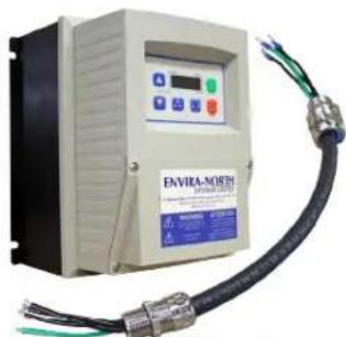
CONTROL OPTIONS
Essential AIR FAN CONTROL
VFD
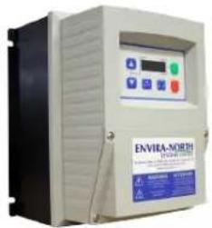
text_image
ENVIRA-NORTH ENVIRA-NORTH• Wall Mounted Variable Frequency Drive (VFD) Configuration
- Minimal Distance Between VFD & HVLS Fan
• One Per Fan Required
ZoneAIR FAN CONTROL
VFD

Mount Plate
text_image
ENVIRA-NORTH ENVIRA-NORTH ENVIRA-NORTH ENVIRA-NORTH ENVIRA-NORTH ENVIRA-NORTH ENVIRA-NORTH ENVIRA-NORTH ENVIRA-NORTH ENVIRA-NORTH ENVIRA-NORTH ENVIRA-NORTH ENVIRA-NORTH ENVIRA-NORTH ENVIRA-NORTH ENVIRA-NORTH ENVIRA-NORTH ENVIRA-NORTHWiring Harness
- Fan Mounted VFD
• One ZoneAir Control Per Fan Required
• Package Includes Mounting Plate + Wiring Harness - Designed to Provide a Single Control for Multiple Fans
- Requires Additional Controls

text_image
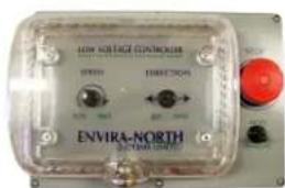
LOW KOREA CONTROLLER ENVIRA-NORTH 2014-03-2015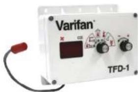
text_image
Varifan® TFD-1LOW VOLTAGE CONTROL (LVC)
• Controls Groups of (up to) Seven (7) Fans
- Lockable Cover
- Stop Button
- Forward/Reverse
- Speed Up/Down
- Toggle Between Manual/Auto Modes
TEMPERATURE CONTROL (TFD-1)
• Programmed for Automatic Fan Speeds
• Constantly Measures Temperature
• Automatically Adjusts to Your Set Points
CommandAIR
VFD
FAN CONTROL

Remote Keypad

100' (30.48m)
CAT 5 Cable

Mount Plate

text_image
ENVIRA-NORTH ENVIRA-NORTH ENVIRA-NORTH ENVIRA-NORTH ENVIRA-NORTH ENVIRA-NORTH ENVIRA-NORTH ENVIRA-NORTH ENVIRA-NORTH ENVIRA-NORTH ENVIRA-NORTH ENVIRA-NORTH ENVIRA-NORTH ENVIRA-NORTH ENVIRA-NORTH ENVIRA-NORTH ENVIRA-NORTH ENVIRA-NORTHWiring Harness
- Fan Mounted VFD
• One CommandAIR Control Per Fan Required
• Package Includes Mounting Plate + Wiring Harness + Control Wire
• and Remote Keypad - Provides Remote Troubleshooting for Fan Mounted VFD
- User Friendly, Simplified Installation and Operation
CONTROL OPTIONS
TouchAIR FAN CONTROL

natural_image
Exterior view of a modern office building (no signage)Touch Pad Control
- Single Point Fan Control
• Controls up to 65 Fans
• CAT-5 Daisy Chain Connections - Intuitive Operation
• Individual and Group Controlling - Remote Diagnostics
• Over 500m (1640') of Wire Distance
• Used in Conjunction with ZoneAIR Fan Control
LinkAIR FAN CONTROL
LinkAir Module
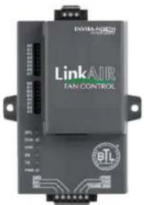
text_image
ENVRA-NORD Link AIR FAN CONTROL eTL- Single Point Fan Control
• Controls up to 247 Fans - Uses BACnet Signal
• Works in Conjunction with Building Automation Controls
• Individual Fan and Group Controlling
• Used in Conjunction with ZoneAIR Fan Control
HAR-MINUS FAN CONTROL
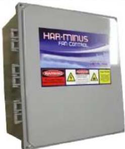
text_image
HAR-MINUS FAN CONTROL- Fan Mounted VFD
• One Har-Minus Control Per Fan
• Very Low Harmonic Transmission - Requires Low Voltage Control
- Designed Specifically for Agricultural Sector
WIND SENSOR
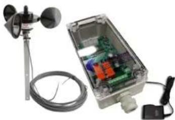
natural_image
Exterior view of an outdoor air conditioning unit with a sensor, cable, and control panel (no visible text or symbols)- For Use With Outdoor Applications
• Automatically Turns Off During High Winds - Compact Design
• Programmable For Customized Applications
LIMITATION OF WARRANTY & LIABILITY
Three Year Limited Warranty
The Altra-Air fans are of industrial grade construction and should provide many years of virtually maintenance-free use. Warranty duration is as follows:
| a) Air foil shaped Blade Lifetime Warranty | |||||||
| b) Aluminum alloy Hub | Lifetime Warranty | ||||||
| c) Motor | 3 year Limited Warra | ||||||
| d) Gear Reducer | 3 year Limited Warra | ||||||
| e) VFD control panel 3 year Limited Warranty | |||||||
| f) Labour | 1 year Limited Warranty | ||||||
| g) Custom fan wraps/paint 1 year Limited Warranty | |||||||
Envira-North warrants that this Product will under normal use and service as specified by Envira-North, operate properly and be free of defects in materials and workmanship for a period of three years from the date of purchase by customer. The term “operate properly” in this context applies to mechanical, electrical and structural functions only. No guarantee, unless and except by separate written agreement, is made regarding dimensions of air movement generated or the effectiveness of this Product for its intended purpose.
Labour Warranty will cover all reasonable costs paid by the customer to an independent contractor (including dealers) to remove, dismantle, reassemble or reinstall any of the warranted Products during the first year that the Product is in service. All receipts are to be submitted to Envira-North which will be paid upon completion of the installation of the Product and after the return of the failed unit. Envira-North will only issue a credit/cheque to the customer/dealer and will not be held responsible for paying the independent contractor.
WARRANTY EXCLUSIONS
Please note that the following may or could void any or all of the above listed Warranties.
- Please note that the following may or could void any or all of the above listed Warranties.
- Not following required installation procedures as in installation guide and all other documentation supplied with the fans and related equipment, supplied by manufacturers of individual fan and control components.
- Not following all relevant codes and ordinances, not limited to National Electrical Code, provincial or state and local building codes.
- Not following electrical engineering industry standards regarding approved method of installing solid-state electrical equipment having characteristics of fans and all components included in this product.
- Any modification to installation, product and or controls without written authorization from Envira-
North, even if attempting to diagnose and or repair a problem.
- Misuse, abuse, accidents, unreasonable use or Acts of God.
• Incorrect electrical current, voltage or supply. - Running fans at higher than recommended speeds.
- Re-setting parameters of any control without prior approval from Envira-North.
- Failure to use all installation and mounting hardware supplied by Envira-North.
- Failure to perform periodic maintenance as detailed in the Envira-North installation guide.
Envira-North reserves the right to make the final determination, based on its own evaluation of the components as to whether:
- The problem in question is the result of a defect in design, workmanship or materials and not the result of error, misuse or abuse on the part of the customer as stated above.
- Whether the problem or defect is material and requires action under this Warranty.
- Whether the remedy of repair or replacement is appropriate.
Envira-North will not be responsible for remedial work necessary to correct installation procedures that do not conform to those established by the instructions, codes and standards, regardless of when the installation occurred.
With regard to electrical and electronic components provided by Envira-North that comprise part of the Products, including motors, motor drives and variable frequency drives, Envira-North relies on the determination by the original manufacturer as to whether the failure of such component was the result of a defect. If the manufacturer of such component determines that there was no defect and therefore refuses to cover it under warranty, Envira-North likewise will not warranty such item unless Envira-North determines that the failure of such electrical or electronic component was the result of a defect of design, workmanship or material within some other part of the products.
WARRANTY DURATION
With respect to replacement or repair rendered, Envira-North warrants that the parts replaced or repaired will operate properly and be free from defects in materials and workmanship for a period of 90 days from the shipment date of the replacement products to the customer, or for the remainder of the original Warranty period, whichever is longer.
WARRANTY CLAIM INSTRUCTIONS
- Contact your original dealer/salesman of the purchase when you first notice problem with the Product.
- It will be the responsibility of the dealer or salesman to assist the customer in determining what Product is causing the problem.
-
If they cannot diagnose the problem, they are to contact Envira-North with all the necessary information.
-
The appropriate department will then be in contact with the customer to determine the cause of the problem.
- Once diagnosed, submit a Purchase Order for a replacement component complete with price.
- Replacement component will be shipped out upon receipt of the PO. This PO allows for an order to be established in the Envira-North System.
- Once the units have been changed over, submit all pre-approved costs to Envira-North for payment.
- No credits or cheques will be issued until all original products are received back at Envira-North or unless Envira-North directs otherwise.
RECOMMENDED MAINTENANCE SCHEDULE
- No maintenance shall be done on the fan, mount or guy wires while it is in operation or powered.
- No maintenance shall be done on the fan controller while powered unless the task involves reprogramming or troubleshooting the electrical system.
- No maintenance shall be done within a 6m horizontal radius of the fan and 4 ft below and none above the blade level while it is in operation.
- While doing maintenance on the fan, mount, or guy wires, a safety barrier shall be erected at a radius of 6m of the centre of the fan.
- The fan controller shall be locked out while maintenance is ongoing on the fan, mount, or guy wires.
- All personnel working on the fan, mount, or guy wires, shall wear the appropriate personal safety equipment as mandated by local, provincial, and national regulations.
- A risk assessment shall be performed before any maintenance is done on the fan, mount, guy wires and fan controller.
- A tailboard meeting shall be performed before any work is done. A checklist shall be completed and shall include any emergency contacts for the area.
POWER UNIT
MOTOR
Our motor or gearmotor manufacturers supply Envira-North with motors/gearmotors built for our application. Designed for use with variable frequency drives; they are wound with 200°C moisture resistant Inverter Spike Resistant (ISR) magnetic wire which dramatically extends the life of the motor compared to motors with non-ISR wire. They have a three year limited warranty.
MAINTENANCE SCHEDULE
Initial Six Months
- Check for hot spots
• Re-tighten all loose electrical connections
Repeat Every Eighteen Months Thereafter
GEAR REDUCER / MOTOR
Altra-Air Fans are driven through Nord Helical Gear Reducers/Gearmotors. Nord is the best gear reducer for our particular application in terms of precision, durability, efficiency, reliability and quiet operation. They have a three year limited warranty.
MAINTENANCE SCHEDULE
Initial Eighteen Months
- Check oil level
Change Oil Every 20,000 Hours of Normal Use
BLADES
The airfoil blades are designed for maximum efficiency and quietness with a minimum air disruption directly below the fan. All our blade shapes are extruded from 6063-aluminum alloy and heat-treated to T-5 condition. They are anodized to .0004 10 Microns clear for corrosion resistance and ease of cleaning. The blades have a lifetime warranty.
MAINTENANCE SCHEDULE
Initial Six Months
- Ensure blades are intact, level and clean as required
Every Eighteen to Thirty-Six Months Thereafter
DROP / MOUNTING
The drop and mounting system is designed to prevent vibration or horizontal movement from being transferred back into the building structure. The system is easily installed in almost any building and allows fans to hang level from beams.
MAINTENANCE SCHEDULE
Initial Six Months
• Physical check of fan guy wires, re-tightening of clamps if required
- Check all nuts/bolts/clamps (missing/loose/damaged)
- Physical check of safety cable, re-tightening of clamps if required
After Eighteen Months Thereafter
CONTROL PANEL
Altra-Air controls are variable frequency drives which provide soft start/stop, variable speed control and overload protection for the motors. The VFD also allows fan control to be automated and/or integrated with other systems. The controls come with a three year limited warranty.
MAINTENANCE SCHEDULE
Initial Twelve Months
- Check for loose/discoloured wires
- Check for hot spots
• Re-tighten all loose electrical connections
Every Eighteen Months Thereafter
NOTE: Maintenance schedule is based on running 5,000 hrs / year and is a guide line to ensure safe and continuous operation of the fan(s). In case of extreme operating (e.g. high humidity, aggressive environment or large temperature variations), shorter intervals between service is recommended.
Tel: 1-519-527-2198 Fax: 1-519-527-2560
Toll Free: 1-886-771-7766
bigair@enviranorth.com
92 Railway St. P.O Box 668
Seaforth, Ontario
Canada N0K 1W0
enviranorth.com